EP2616739B1 - A lighting head, a fastening fixture and a reflector for a lighting system - Google Patents
A lighting head, a fastening fixture and a reflector for a lighting system Download PDFInfo
- Publication number
- EP2616739B1 EP2616739B1 EP11825537.1A EP11825537A EP2616739B1 EP 2616739 B1 EP2616739 B1 EP 2616739B1 EP 11825537 A EP11825537 A EP 11825537A EP 2616739 B1 EP2616739 B1 EP 2616739B1
- Authority
- EP
- European Patent Office
- Prior art keywords
- unit
- light source
- lighting
- reflector
- ballast
- Prior art date
- Legal status (The legal status is an assumption and is not a legal conclusion. Google has not performed a legal analysis and makes no representation as to the accuracy of the status listed.)
- Not-in-force
Links
- 238000012545 processing Methods 0.000 description 44
- 238000000034 method Methods 0.000 description 32
- 238000005259 measurement Methods 0.000 description 28
- 238000012544 monitoring process Methods 0.000 description 12
- 230000002085 persistent effect Effects 0.000 description 8
- 238000004891 communication Methods 0.000 description 7
- 238000004590 computer program Methods 0.000 description 7
- 230000006870 function Effects 0.000 description 3
- 230000004044 response Effects 0.000 description 3
- 230000008859 change Effects 0.000 description 2
- 230000001419 dependent effect Effects 0.000 description 2
- 230000000694 effects Effects 0.000 description 2
- 229910052736 halogen Inorganic materials 0.000 description 2
- 150000002367 halogens Chemical class 0.000 description 2
- 239000002184 metal Substances 0.000 description 2
- 230000009471 action Effects 0.000 description 1
Images

Classifications
-
- F—MECHANICAL ENGINEERING; LIGHTING; HEATING; WEAPONS; BLASTING
- F21—LIGHTING
- F21V—FUNCTIONAL FEATURES OR DETAILS OF LIGHTING DEVICES OR SYSTEMS THEREOF; STRUCTURAL COMBINATIONS OF LIGHTING DEVICES WITH OTHER ARTICLES, NOT OTHERWISE PROVIDED FOR
- F21V7/00—Reflectors for light sources
- F21V7/0025—Combination of two or more reflectors for a single light source
-
- F—MECHANICAL ENGINEERING; LIGHTING; HEATING; WEAPONS; BLASTING
- F21—LIGHTING
- F21V—FUNCTIONAL FEATURES OR DETAILS OF LIGHTING DEVICES OR SYSTEMS THEREOF; STRUCTURAL COMBINATIONS OF LIGHTING DEVICES WITH OTHER ARTICLES, NOT OTHERWISE PROVIDED FOR
- F21V14/00—Controlling the distribution of the light emitted by adjustment of elements
- F21V14/04—Controlling the distribution of the light emitted by adjustment of elements by movement of reflectors
-
- F—MECHANICAL ENGINEERING; LIGHTING; HEATING; WEAPONS; BLASTING
- F21—LIGHTING
- F21V—FUNCTIONAL FEATURES OR DETAILS OF LIGHTING DEVICES OR SYSTEMS THEREOF; STRUCTURAL COMBINATIONS OF LIGHTING DEVICES WITH OTHER ARTICLES, NOT OTHERWISE PROVIDED FOR
- F21V17/00—Fastening of component parts of lighting devices, e.g. shades, globes, refractors, reflectors, filters, screens, grids or protective cages
- F21V17/002—Fastening of component parts of lighting devices, e.g. shades, globes, refractors, reflectors, filters, screens, grids or protective cages with provision for interchangeability, i.e. component parts being especially adapted to be replaced by another part with the same or a different function
-
- F—MECHANICAL ENGINEERING; LIGHTING; HEATING; WEAPONS; BLASTING
- F21—LIGHTING
- F21V—FUNCTIONAL FEATURES OR DETAILS OF LIGHTING DEVICES OR SYSTEMS THEREOF; STRUCTURAL COMBINATIONS OF LIGHTING DEVICES WITH OTHER ARTICLES, NOT OTHERWISE PROVIDED FOR
- F21V17/00—Fastening of component parts of lighting devices, e.g. shades, globes, refractors, reflectors, filters, screens, grids or protective cages
- F21V17/10—Fastening of component parts of lighting devices, e.g. shades, globes, refractors, reflectors, filters, screens, grids or protective cages characterised by specific fastening means or way of fastening
-
- F—MECHANICAL ENGINEERING; LIGHTING; HEATING; WEAPONS; BLASTING
- F21—LIGHTING
- F21V—FUNCTIONAL FEATURES OR DETAILS OF LIGHTING DEVICES OR SYSTEMS THEREOF; STRUCTURAL COMBINATIONS OF LIGHTING DEVICES WITH OTHER ARTICLES, NOT OTHERWISE PROVIDED FOR
- F21V13/00—Producing particular characteristics or distribution of the light emitted by means of a combination of elements specified in two or more of main groups F21V1/00 - F21V11/00
- F21V13/12—Combinations of only three kinds of elements
-
- F—MECHANICAL ENGINEERING; LIGHTING; HEATING; WEAPONS; BLASTING
- F21—LIGHTING
- F21V—FUNCTIONAL FEATURES OR DETAILS OF LIGHTING DEVICES OR SYSTEMS THEREOF; STRUCTURAL COMBINATIONS OF LIGHTING DEVICES WITH OTHER ARTICLES, NOT OTHERWISE PROVIDED FOR
- F21V5/00—Refractors for light sources
- F21V5/04—Refractors for light sources of lens shape
- F21V5/048—Refractors for light sources of lens shape the lens being a simple lens adapted to cooperate with a point-like source for emitting mainly in one direction and having an axis coincident with the main light transmission direction, e.g. convergent or divergent lenses, plano-concave or plano-convex lenses
-
- F—MECHANICAL ENGINEERING; LIGHTING; HEATING; WEAPONS; BLASTING
- F21—LIGHTING
- F21V—FUNCTIONAL FEATURES OR DETAILS OF LIGHTING DEVICES OR SYSTEMS THEREOF; STRUCTURAL COMBINATIONS OF LIGHTING DEVICES WITH OTHER ARTICLES, NOT OTHERWISE PROVIDED FOR
- F21V7/00—Reflectors for light sources
- F21V7/04—Optical design
- F21V7/06—Optical design with parabolic curvature
Definitions
- the present invention relates to the field of lighting systems, in particular to a lighting head, a fastening fixture and a reflector for providing light in a lighting system.
- a lighting system normally comprises at least one lighting head having a reflector arranged to dispurse light from a light source located at suitable focal point of the reflector.
- This disclosure relates to a fastening fixture for a lighting head arranged to detachably connect a reflector to the lighting head according to claim 1.
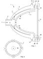
- Fig. 1 shows a side view of embodiments of a lighting head 1, a fastening fixture 5 and a reflector 6 according to the invention.
- the lighting head 1 comprises a first reflector body 2 having a first reflector 4.
- the first reflector body 2 comprises a first aperture 8 for receiving a light source 7.
- the light source 7 may be entered through an opening at the back end of the first reflector body 2 and may be extended through the first aperture 8 such that at least a portion of the light from the light source 7 may be reflected of the first reflector 4.
- the first reflector 4 comprises a first reflective surface 4A which is arranged to reflect light from the light source 7 out through the larger forward facing opening of the first reflector body 2.
- the first reflector body 2 may also comprise a fastening member 3 for safely securing the light source 7 as it is has been entered through the opening at the back end of the first reflector body 2.
- the fastening member 3 enables the light source 7 to be moved forward or backwards through the opening at the back end of the first reflector 2 and be tightly secured to the first reflector body 2 once a suitable placement of the light source 7 has been found.
- the lighting head 1 may also comprise fastening fixure 5.
- the fastening fixture 5 may be any form of fastener, fastening device or holding device.
- the fastening fixture 5 may be movabely arranged between a first open position and a second locked position. In Fig. 1 , the fastening fixture 5 is shown in its second locked position.
- the fastening fixture 5 may be arranged to move between the first open position and the second locked position through a moving member 5C.
- the moving member 5C may be connected between the first reflector body 2 and the fastening fixture 5.
- the moving member 5 may preferably be a spring operated member or any form of member enabling the fastening fixture 5 to be rotated around the centre of the member 5C between a first open position and a second locked position.
- the fastening fixture 5 may also comprise a first receiving means 5A for detachably connecting a lens 10 to the lighting head 1 in front of the light source 7.
- a receiving means is a first reception cavity 5A.
- the lens 10 may be placed in the first reception cavity 5A of the fastening fixture 5 and be securely fastened to the first reflector body 2 in front of the light source 7 by moving the fastening fixture 5 into the second locked position (as shown in Fig. 1 ).
- the fastening fixture 5 further comprises a second receiving means for detachably connecting a second reflector 6 to the lighting head 1.
- a second receiving means is at least one second reception cavity 5B.
- the at least one second reception cavity 5B of the fastening fixture 5 may be arranged to receive a fastening means 6B of the second reflector 6.
- the fastening means 6B of the second reflector 6 may be placed in the second reception cavity 5B of the fastening fixture 5 and be securely fastened to the first reflector body 2 by moving the fastening fixture 5 into the second locked position (as shown in Fig. 1 ).
- the fastening fixture 5 may be arranged to securely fasten the second reflector 6 to the first reflector body 2 such that the light source 7 may extend through an aperture 9 of the second reflector 6 configured to receive the light source 7.
- the fastening fixture 5 may also be arranged to securely fasten the second reflector 6 such that at least a portion of the light from the light source 7, when extended through the aperture 9 of the second reflector 6, is reflected of a reflective surface 6A of the second reflector 6 out through the larger forward facing opening of the first reflector body 2.
- any number of fastening fixtures 5 may be used in order to detachably connect a second reflector 6 and/or the lens 10 to the first reflector body 2.
- four fastening fixtures 5 are arranged on the first reflector body 2.
- Fig. 2 also shows the fastening fixtures 5 in their second locked position.
- the second reflector 6 is arranged to be detachably connected to the lighting head 1.
- the second reflector 6 is arranged to be received in the first reflector body 2 of the lighting head 1.
- the second reflector 6 may comprise an aperture 9 for receiving a light source 7.
- the second reflector 6 may also comprise fastening means 6B arranged to be detachably connected to the lighting head 1.
- the fastening means 6B of the second reflector may be arranged so as to enable the light source 7 to extend through the aperture 9.
- the fastening means 6B of the second reflector may be arranged such that the light source 7 may extends through the aperture 9.
- the fastening means 6B of the second reflector may be arranged to enable the second reflector 6 to be positioned such that at least a portion of the light from the light source 7 may be reflected of the reflective surface 6A of the second reflector 6.
- the fastening means 6B may be arranged to be detachably mounted and securely fastened by at least one fastening fixture 5 comprised in the lighting head 1.
- the fastening means 6B may comprise at least one protrusion of the second reflector 6 extending away from the forward faceing opening of the reflector 6 located opposite the aperture 9.
- the at least one protrusion of the second reflector 6 extending away from the forward faceing opening of the reflector 6 and towards the fastening fixture 5 of the first reflector body 2 may be arranged to be received by the second reception cavity 5B of the at least one fastening fixture 5 of the first reflector body 2 in the lighting head 1.
- fastening means 5 may comprise any form of protrusion or extension of the second reflector 6 arranged to be received by the second reception cavity 5B of the at least one fastening fixture 5 of the first reflector body 2 in the lighting head 1
- fastening means 5 may also comprise any form of fastener, fastening device or holding device arranged to be received by the at least one fastening fixture 5 of the first reflector body 2 in the lighting head 1.
- the embodiments of the invention described above provides for a lighting head 1 in which a first reflector 4 may be easily replaced by an exchangeable second reflector 6.
- a first reflector 4 may be easily replaced by an exchangeable second reflector 6.
- this allows an operator of the lighting head 1 to adjust the reflecting properties of the lighting head 1 in a simple and cost-efficient manner.
- the invention also relates to a method, devices and system for providing continuous light.
- This relates to the field of lighting systems, in particular to a method, devices and system for providing continuous light in a continuous lighting system.
- a continuous lighting system normally comprises at least one lighting unit having at least one light source being connected via a power cable to a ballast or generator unit in order to receive a power supply signal.
- this disclosure relates to a lighting unit comprising at least one light source for providing continuous light, the lighting unit comprising a processing unit configured to send control signals to a ballast or generator unit for controlling the power supplied to the at least one light source by the ballast or generator unit.
- this disclosure also relates to a method for use in a lighting unit comprising at least one light source for providing continuous light, comprising the steps of: sending control signals to a ballast or generator unit for controlling the power supplied to the at least one light source by the ballast or generator unit.
- this disclosure also relates to a cable comprising a first communication path being arranged to transmit control signals to a ballast or generator unit and a second communication path being arranged to transmit a power signal from the ballast or generator unit to a lighting unit.
- this disclosure also relates to a cable connector comprising electrical pin connectors, wherein at least a first electrical pin connector is arranged to receive control signals to a ballast or generator unit and at least a second electrical pin connector is arranged to transmitting a power signal from the ballast or generator unit, the pin(s) of the at least second electrical pin connector being longer than the pin(s) of the first pin electrical connector.
- this disclosure also relates a ballast or generator for providing a power signal to lighting unit comprising a cable connector.
- Fig. 3 shows embodiments of a lighting unit 10, a cable 110 and connectors 19, 112 for use in a lighting system 100 for providing continous light according to the invention.
- Fig. 3 shows a remote control unit 11.
- the remote control unit 11 may be used by an operator of the lighting system 100 to transmit control signals and/or other data information to a lighting unit 10.
- the remote control unit 11 may comprise input devices for receiving inputs from an operator of the remote control unit 11, and may also comprise indicating means for displaying information to the operator of the remote control unit 11, such as, for example, a display and/or indicator lights.
- the input devices may be used by an operator to control the performance of a light source 113 of the lighting unit 10.
- control functions for controlling the performance of a light source 113 may be, for example, dimming the light source 113, controlling the fan speed of a fan unit 114, turning the light source 113 on and off, etc.
- the remote control unit 11 may comprise a radio unit (for example, a radio transmitter, radio receiver or radio transceiver) arranged to relay control signals and/or other data information to/from other radio units (for example, a radio transmitter, radio receiver or radio transceiver), such as, for example, a radio unit 120 in a computer 119 and/or a radio unit 12 in the lighting unit 10.
- the radio unit 12 in the lighting unit 10 may also be referred to a receiving unit, although it may also be used for transmitting control signals and/or data information back to the remote control unit 11 and/or the computer 119.
- the remote control unit 11 may be any handheld device comprising a radio unit arranged to communicate with another radio unit located in the lighting unit 10.
- the computer 119 comprising the radio unit 120 may also be arranged to relay control signals and/or other data information to/from other radio units, such as, the remote control unit 11 and/or radio unit 12 in the lighting unit 10.
- the lighting unit 10 may also be referred to a lamp or lamp unit.
- the radio unit 12 may be communicatively connected to a processing unit 13.
- the processing unit 13 may further be communicatively connected to all of the following units that may be present in the lighting unit 10: a persistent memory unit 14, a time counter 15, one or more input devices 16, a display 17, a cable connector 19, at least one light source 113, a fan unit 114, a temperature sensor 115, a zero-cross detector 116, and a light source voltage monitoring unit 117.
- the lighting unit 10 may also comprise an ignitor unit 118.
- the ignitor unit 118 may be arranged to boosting the voltage to ignite the bulb.
- the lighting unit 10 may be connected to a ballast or generator unit 111 via the cable connector 19.
- the time counter 15, which also may be implemented as a software in the processing unit 12, may be arranged to, for example, count the hours of the usage of the light source 113 and store this time information in the persistent memory unit 14.
- the one or more input devices 16 may represent different control functions of the lighting unit 10 and may comprise, for example, a dimmer knob arranged to indicate a specific amout of dimming of the light source 113 desired by an operator (e.g. a dimming percentage of the maximum effect of the light source 113) and/or a fan mode button for setting the speed of the fan unit 114 (e.g. in order to eliminate any sound from the lighting unit 113) and/or an on/off-button for turning the light source 113 on or off.
- a dimmer knob arranged to indicate a specific amout of dimming of the light source 113 desired by an operator (e.g. a dimming percentage of the maximum effect of the light source 113) and/or a fan mode button for setting the speed of the fan unit 114 (e
- the display 17 may be used by the processing unit 13 for displaying information indicative of the performance of the at least one light source 113.
- the display 17 may also be used by the processing unit 13 for displaying information showing the selected setting(s) of the lighting unit 10, a time counter value of the usage of the light source 113, which radio channel the radio unit 12 in the lighting unit 10 is set to, and which group of lighting units the lighting unit 10 belong to (if any).
- the cable connector 19 may be arranged to connect the lighting unit 10 with a ballast or generator unit 111 via a cable 110.
- the cable connector 19 may be arranged to transmit control signals to the ballast or generator unit 111 through the cable 110 and receiving a power signal from the ballast or generator unit 111 through the same cable 110 in response to the control signals sent to the ballast or generator unit 111.
- the control signals may be DMX control signals and may also comprise DMX logical power signals.
- the received power signal provides power to the light source 113.
- the cable connector 19 and the cable connecting the lighting unit 10 and the ballast or generator unit 111 are described in more detail below with reference to Figs. 5-6 .
- the light source 113 may be a Metal Hallide Discharge (HMI) bulb or a standard halogen bulb. However, these examples are not to be considered limited, since other similar bulbs may also be used in a similar manner by the invention.
- HMI Metal Hallide Discharge
- the fan unit 114 may be arranged to cool, i.e. lower the temperature, of the light source 113.
- the zero cross detector 116 may sense the voltage polarity-switching at the zero voltage point, of the bulb voltage.
- the light source voltage monitoring unit 117 may monitor the voltage over the light source.
- the processing unit 12 in the lighting unit 10 may be configured to send control signals to a ballast or generator unit 111 for controlling the power supplied to the at least one light source 113 by the ballast or generator unit 111.
- the control signals may be DMX control signals and may also comprise DMX logical power signals.
- the control signals may be based on received or retrieved measurements indicative of the performance of the at least one light source 113. These measurements signals may originate from or be retrieved from, for example, the persistent memory unit 14, the time counter 15, the fan unit 114, the temperature sensor 115, the zero-cross detector 116, and/or the light source voltage monitoring unit 117.
- the processing unit 13 may be arranged to receive measurements indicative of the performance of the at least one light source 113 from the temperature sensor 115. The processing unit 13 may then send control signals to a fan unit 114 based on received measurements indicative of the performance of the at least one light source 113 in combination with control signals to a ballast or generator unit 111. This may, for example, be performed in case the processing unit 13 has detected that there is a risk that the light source 113 is going to be overheated, whereby the processing unit 13 may change to fan speed of the fan unit 114 and/or send control signals to a ballast or generator unit 111 to reduce the power to the light source 113.
- the processing unit 13 may be arranged to receive measurements indicative of the performance of the at least one light source 113 from the zero-cross detector 116 and the light source voltage monitoring unit 117.
- the processing unit 13 may be arranged to send control signals to the ballast or generator unit 111 based on received measurements indicative of the performance of the at least one light source 113 from the zero-cross detector (116) and/or the light source voltage monitoring unit 117. This may, for example, be performed in case the processing unit 13 detects that the ignitor unit 118 being arranged to ignite the light source 113, it not successful in igniting the light source 113.
- the processing unit 13 may send control signals to the ballast or generator unit 111 to stop providing power signal to the light source 113.
- the processing unit 12 may be configured to receive control signals and/or data information from the radio unit 12 and/or from the one or more input devices 16 for controlling the performance of the at least one light source 113.
- the processing unit 12 may also be configured to receive or retrieve measurements indicative of the actual performance of the light source 113. These measurements signals may originate from or be retrieved from, for example, the persistent memory unit 14, the time counter 15, the fan unit 114, the temperature sensor 115, the zero-cross detector 116, and/or the light source voltage monitoring unit 117.
- the processing unit 13 may be configured to modify the received control signals based on the received measurements indicative of the performance of the light source 113.
- the processing unit 13 may also be configured to send these modified control signals to a ballast or generator unit 111.
- the processing unit 12 may comprise logic for performing the functionality of the lighting unit 10. This functionality may be implemented by means of a software or computer program.
- the processing unit 12 may also comprise storage means or a memory unit 14 for storing the computer program and processing means, such as e.g. a microprocessor or microcontroller, for executing the computer program.
- the storage means may also be readable storage medium separated from, but connected to the processing unit 12.
- the processing unit 12 may use its processing means to execute a certain part of the software or computer program which may be stored in its storage means 14.
- the processing unit 12 in the lighting unit 10 may be configured to perform the steps of the method as described with reference to Fig. 4 .
- a computer program product may be provided for use in a processing unit 12 in a lighting unit 10 as described in any of the embodiments above, which comprises computer readable code means, which when run in the processing unit 12 in the transmitting node causes the processing unit 12 to perform any one of the steps described in any of the methods described above.
- the code means of the computer program product may be stored on any form of readable storage medium, such as, for example, in the persistent memory 14.
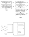
- Fig. 4 shows a flowchart of an embodiment of the method for use in a lighting unit 10 comprising at least one light source 113 for providing continuous light.
- the processing unit 13 may receive or retrieve measurements indicative of the performance of the light source 113. These measurements may originate from or be retrieved from, for example, the persistent memory unit 14, the time counter 15, the fan unit 114, the temperature sensor 115, the zero-cross detector 116, and/or the light source voltage monitoring unit 117.
- step S42 the processing unit 13 may send control signals to a ballast or generator unit 111, wherein the control signals may be based on the received measurements indicative of the performance of the light source 113.
- the control signals may control the power supplied to the light source 113 by the ballast or generator unit 111.
- Fig. 5 illustrates a flowchart of another embodiment of the method for use in a lighting unit 10 comprising at least one light source 113 for providing continuous light.
- the processing unit 13 may receive control signals for controlling the performance of the light source 113.
- the control signal may be wirelessly received from a remote control unit 11 or received manually through the input devices 18 on the lighting unit 10.
- the processing unit 13 may receive measurements indicative of the performance of the light source 113. These measurements may originate from or be retrieved from, for example, the persistent memory unit 14, the time counter 15, the fan unit 114, the temperature sensor 115, the zero-cross detector 116, and/or the light source voltage monitoring unit 117.
- step S53 the processing unit 13 may modify the received control signals based on the received measurements in the lighting unit 10 indicative of the performance of the light source 113.
- step S54 the processing unit 13 may send the modified control signals to a ballast or generator unit 111.
- the control signals may control the power supplied to the light source 113 by the ballast or generator unit 111.
- Fig. 6 shows a side view of an embodiment of a connector for the cable shown in Fig. 3 .
- the cable 110 may comprise a first communication path (110A in Fig. 3 ) being arranged to transmit control signals to a ballast or generator unit 111 and a second communication path (110B in Fig. 3 ) being arranged to transmit a power signal from the ballast or generator unit 111 to a lighting unit 10.
- the control signals are DMX control signals and DMX logical power signals following the DMX protocol.
- the cable connector 110 may be arranged to receive control signals to a ballast or generator unit 111 and transmit a power signal from the ballast or generator unit 111.
- the control signals are DMX control signals and DMX logical power signals.
- the cable connector 110 may comprise electrical pin connectors, wherein at least a first electrical pin connector may be arranged to receive control signals to a ballast or generator unit 111 and at least a second electrical pin connector may be arranged to transmitting a power signal from the ballast or generator unit 111.
- the pin(s) of the at least second electrical pin connector may be longer than the pin(s) of the first pin electrical connector. This may be performed so as to ensure that the power supply to the light source 113 is stopped, before the control signals to the ballast or generator 111.
- the cable connecter may advantageously be fitted to a ballast or generator unit 111 for providing a power signal to lighting unit 10.
- One reason to have one cable with cords for both DMX control of the ballast or generator unit 111, and the power from the ballast to the light source 113 (e.g. HMI bulb) is that it is simple and easier to use than when having multiple cables.
- DMX communication will come from the lighting unit 10 and not from an external DMX controlling device.
- the Microcontroller has a program that controls the Ballast power and the fan speed and the bulb ignitor. The control is dependent of the inputs to the microcontroller
- a lighting unit 10 comprising at least one light source 113 for providing continuous light.
- the lighting unit 10 comprising a processing unit 13 configured to send control signals to a ballast or generator unit 111 for controlling the power supplied to the at least one light source 113 by the ballast or generator unit 111.
- the processing unit 13 is configured to send the control signals based on received measurements indicative of the performance of the at least one light source 113.
- the lighting unit 10 comprises a receiving unit configured to receive control signals for controlling the performance of the at least one light source 113, and wherein the processing unit 13 is configured to modify the received control signals based on received measurements in the lighting unit 10 indicative of the performance of the at least one light source 113.
- the processing unit 13 is arranged to receive measurements indicative of the performance of the at least one light source 113 from a temperature sensor 115 in the lighting unit 10.
- the processing unit 13 is arranged to send control signals to a fan unit 114, said fan unit 114 being arranged to lower the temperature of the at least one light source 113, based on received measurements indicative of the performance of the at least one light source 113 and the control signals to the ballast or generator unit 111.
- the processing unit 13 is arranged to receive measurements indicative of the performance of the at least one light source 113 from a zero-cross detector 116 and a light source voltage monitoring unit 117.
- the processing unit 13 is arranged to send control signals to a ballast or generator unit 111 based on received measurements indicative of the performance of the at least one light source 113 from the zero-cross detector 116 and/or the light source voltage monitoring unit 117, in order to control an ignitor unit 118 in the lighting unit 10, said ignitor unit 118 being arranged to ignite the light source 113 in the lighting unit 10.
- the light source 113 is a Metal Hallide Discharge (HMI) lamp or a standard halogen lamp.
- HMI Metal Hallide Discharge
- the processing unit 13 is arranged to display information on a display unit 17 on the continuous lighting unit 10 indicative of the performance of the at least one light source 113.
- the receiving unit is a radio unit 12 configured to wirelessly receive the control signals from a remote control unit 11.
- the receiving unit is at least one input device 18 configured to receive the control signals manually on the continuous lighting unit 10.
- the lighting unit 10 further comprises a connecting unit 19 for connecting to a cable device 110, the connecting unit 19 being arranged to send control signals to the ballast or generator unit 111 through the cable device 110 and receiving a power signal from the ballast or generator unit 111 through the same cable device 110 in response to the control signals sent to the ballast or generator unit 111.
- a method for use in a lighting unit 1 comprising at least one light source 113 for providing continuous light.
- the method comprising the step of: sending control signals to a ballast or generator unit 111 for controlling the power supplied to the at least one light source 113 by the ballast or generator unit 111.
- the control signals based on received measurements indicative of the performance of the at least one light source 113.
- the method further comprises the steps of: receiving control signals for controlling the performance of the at least one light source 113; received measurements indicative of the performance of the at least one light source 113; and modifying the received control signals based on the received measurements in the lighting unit 10 indicative of the performance of the at least one light source 113.
- the method further comprises the step of: sending the modified control signals to a ballast or generator unit 111.
- the method further comprises the step of: receiving measurements indicative of the performance of the at least one light source 113 from a temperature sensor 115 in the lighting unit 10.
- the method further comprises the step of: sending control signals to a fan unit 114 in the lighting unit 10 based on received measurements indicative of the performance of the at least one light source 113 and the sent modified control signals to a ballast or generator unit 111.
- the method further comprises the step of: receiving measurements indicative of the performance of the at least one light source 113 from a zero-cross detector 116 and a light source voltage monitoring unit 117.
- the method further comprises the step of: sending modified control signals to a ballast or generator unit 111 based on received measurements indicative of the performance of the at least one light source 113 from the zero-cross detector 116 and/or the light source voltage monitoring unit 117, in order to control an ignitor unit 118 in the lighting unit 10.
- the method further comprises the step of: displaying information on a display unit 17 in the continuous lighting unit 10 indicative of the performance of the at least one light source 113.
- the method further comprises further comprising the step of: wirelessly receiving the control signals from a remote control unit 11.
- the method further comprises the step of: receiving the control signals manually on the continuous lighting unit 10.
- the method further comprises the step of: send control signals to the ballast or generator unit 111 through a cable device 110 and receiving a power signal from the ballast or generator unit 111 through the same cable device 110 in response to the control signals sent to the ballast or generator unit 111.
- a cable 110 comprising a first communication path 110A being arranged to transmit control signals to a ballast or generator unit 111 and a second communication path 110B being arranged to transmit a power signal from the ballast or generator unit 111 to a lighting unit 10.
- control signals are DMX control signals and DMX logical power signals.
- a cable connector 110 is provided.
- the cable connector 110 is arranged to receive control signals to a ballast or generator unit 111 and transmit a power signal from the ballast or generator unit 111.
- control signals are DMX control signals and DMX logical power signals.
- the cable connector 110 comprises electrical pin connectors, wherein at least a first electrical pin connector is arranged to receive control signals to a ballast or generator unit 111 and at least a second electrical pin connector is arranged to transmitting a power signal from the ballast or generator unit 111, the pin(s) of the at least second electrical pin connector being longer than the pin(s) of the first pin electrical connector.
- a ballast or generator 111 for providing a power signal to lighting unit 10 is provided.
- the ballast or generator 111 comprising a cable connector 110 as described above.
Landscapes
- Engineering & Computer Science (AREA)
- General Engineering & Computer Science (AREA)
- Circuit Arrangement For Electric Light Sources In General (AREA)
Description
- The present invention relates to the field of lighting systems, in particular to a lighting head, a fastening fixture and a reflector for providing light in a lighting system.
- A lighting system normally comprises at least one lighting head having a reflector arranged to dispurse light from a light source located at suitable focal point of the reflector.
- Document
US 1 880 399 A discloses a fastening fixture for a lighting head according to the preamble ofclaim 1. - SUMMARY This disclosure relates to a fastening fixture for a lighting head arranged to detachably connect a reflector to the lighting head according to
claim 1. - Further aspects of the present invention are set out in the dependent claims.
- The above and other features and advantages of the present invention will become readily apparent to those skilled in the art by the following detailed description of exemplary embodiments thereof with reference to the accompanying drawings, wherein:
- Fig. 1
- illustrates a side view of an embodiment according to the invention,
- Fig. 2
- illustrates a front view of an embodiment according to the invention shown in
Fig. 1 , - Fig. 3
- illustrates embodiments of a device and a system providing continous light according to the invention,
- Fig. 4
- illustrates a flowchart of an embodiment of the method according to the invention.
- Fig. 5
- illustrates a flowchart of another embodiment of the method according to the invention.
- Fig. 6
- illustrates a side view of an embodiment of a connector for the cable device shown in
Fig. 3 . - The figures are schematic and simplified for clarity, and they merely show details which are essential to the understanding of the invention, while other details have been left out. Throughout, the same reference numerals are used for identical or corresponding parts or steps.
-
Fig. 1 shows a side view of embodiments of alighting head 1, a fasteningfixture 5 and areflector 6 according to the invention. Thelighting head 1 comprises afirst reflector body 2 having afirst reflector 4. Thefirst reflector body 2 comprises afirst aperture 8 for receiving alight source 7. Thelight source 7 may be entered through an opening at the back end of thefirst reflector body 2 and may be extended through thefirst aperture 8 such that at least a portion of the light from thelight source 7 may be reflected of thefirst reflector 4. Thefirst reflector 4 comprises a firstreflective surface 4A which is arranged to reflect light from thelight source 7 out through the larger forward facing opening of thefirst reflector body 2. - The
first reflector body 2 may also comprise a fasteningmember 3 for safely securing thelight source 7 as it is has been entered through the opening at the back end of thefirst reflector body 2. The fasteningmember 3 enables thelight source 7 to be moved forward or backwards through the opening at the back end of thefirst reflector 2 and be tightly secured to thefirst reflector body 2 once a suitable placement of thelight source 7 has been found. - The
lighting head 1 may also comprise fasteningfixure 5. Thefastening fixture 5 may be any form of fastener, fastening device or holding device. The fasteningfixture 5 may be movabely arranged between a first open position and a second locked position. InFig. 1 , the fasteningfixture 5 is shown in its second locked position. The fasteningfixture 5 may be arranged to move between the first open position and the second locked position through a movingmember 5C. The movingmember 5C may be connected between thefirst reflector body 2 and thefastening fixture 5. The movingmember 5 may preferably be a spring operated member or any form of member enabling thefastening fixture 5 to be rotated around the centre of themember 5C between a first open position and a second locked position. - The fastening
fixture 5 may also comprise afirst receiving means 5A for detachably connecting alens 10 to thelighting head 1 in front of thelight source 7. One example of such a receiving means is afirst reception cavity 5A. Thelens 10 may be placed in thefirst reception cavity 5A of the fasteningfixture 5 and be securely fastened to thefirst reflector body 2 in front of thelight source 7 by moving the fasteningfixture 5 into the second locked position (as shown inFig. 1 ). - According to some embodiments of the invention, the fastening
fixture 5 further comprises a second receiving means for detachably connecting asecond reflector 6 to thelighting head 1. One example of such a second receiving means is at least onesecond reception cavity 5B. The at least onesecond reception cavity 5B of the fasteningfixture 5 may be arranged to receive a fastening means 6B of thesecond reflector 6. The fastening means 6B of thesecond reflector 6 may be placed in thesecond reception cavity 5B of the fasteningfixture 5 and be securely fastened to thefirst reflector body 2 by moving the fasteningfixture 5 into the second locked position (as shown inFig. 1 ). The fasteningfixture 5 may be arranged to securely fasten thesecond reflector 6 to thefirst reflector body 2 such that thelight source 7 may extend through an aperture 9 of thesecond reflector 6 configured to receive thelight source 7. The fasteningfixture 5 may also be arranged to securely fasten thesecond reflector 6 such that at least a portion of the light from thelight source 7, when extended through the aperture 9 of thesecond reflector 6, is reflected of areflective surface 6A of thesecond reflector 6 out through the larger forward facing opening of thefirst reflector body 2. - It should be noted that any number of fastening
fixtures 5 may be used in order to detachably connect asecond reflector 6 and/or thelens 10 to thefirst reflector body 2. InFig. 2 , four fasteningfixtures 5 are arranged on thefirst reflector body 2.Fig. 2 also shows thefastening fixtures 5 in their second locked position. - The
second reflector 6 is arranged to be detachably connected to thelighting head 1. Thesecond reflector 6 is arranged to be received in thefirst reflector body 2 of thelighting head 1. Thesecond reflector 6 may comprise an aperture 9 for receiving alight source 7. Thesecond reflector 6 may also comprise fastening means 6B arranged to be detachably connected to thelighting head 1. The fastening means 6B of the second reflector may be arranged so as to enable thelight source 7 to extend through the aperture 9. The fastening means 6B of the second reflector may be arranged such that thelight source 7 may extends through the aperture 9. The fastening means 6B of the second reflector may be arranged to enable thesecond reflector 6 to be positioned such that at least a portion of the light from thelight source 7 may be reflected of thereflective surface 6A of thesecond reflector 6. - The fastening means 6B may be arranged to be detachably mounted and securely fastened by at least one fastening
fixture 5 comprised in thelighting head 1. According to some embodimetns, the fastening means 6B may comprise at least one protrusion of thesecond reflector 6 extending away from the forward faceing opening of thereflector 6 located opposite the aperture 9. The at least one protrusion of thesecond reflector 6 extending away from the forward faceing opening of thereflector 6 and towards the fasteningfixture 5 of thefirst reflector body 2 may be arranged to be received by thesecond reception cavity 5B of the at least one fasteningfixture 5 of thefirst reflector body 2 in thelighting head 1. However, it should also be noted that although the fastening means 5 may comprise any form of protrusion or extension of thesecond reflector 6 arranged to be received by thesecond reception cavity 5B of the at least one fasteningfixture 5 of thefirst reflector body 2 in thelighting head 1, the fastening means 5 may also comprise any form of fastener, fastening device or holding device arranged to be received by the at least one fasteningfixture 5 of thefirst reflector body 2 in thelighting head 1. - The embodiments of the invention described above provides for a
lighting head 1 in which afirst reflector 4 may be easily replaced by an exchangeablesecond reflector 6. Advantageously, this allows an operator of thelighting head 1 to adjust the reflecting properties of thelighting head 1 in a simple and cost-efficient manner. - According a further aspect of the invention, the invention also relates to a method, devices and system for providing continuous light.
- This relates to the field of lighting systems, in particular to a method, devices and system for providing continuous light in a continuous lighting system.
- A continuous lighting system normally comprises at least one lighting unit having at least one light source being connected via a power cable to a ballast or generator unit in order to receive a power supply signal.
- According to one aspect, this disclosure relates to a lighting unit comprising at least one light source for providing continuous light, the lighting unit comprising a processing unit configured to send control signals to a ballast or generator unit for controlling the power supplied to the at least one light source by the ballast or generator unit.
- According to yet a further aspect, this disclosure also relates to a method for use in a lighting unit comprising at least one light source for providing continuous light, comprising the steps of: sending control signals to a ballast or generator unit for controlling the power supplied to the at least one light source by the ballast or generator unit.
- According to yet a further aspect, this disclosure also relates to a cable comprising a first communication path being arranged to transmit control signals to a ballast or generator unit and a second communication path being arranged to transmit a power signal from the ballast or generator unit to a lighting unit.
- According to yet a further aspect, this disclosure also relates to a cable connector comprising electrical pin connectors, wherein at least a first electrical pin connector is arranged to receive control signals to a ballast or generator unit and at least a second electrical pin connector is arranged to transmitting a power signal from the ballast or generator unit, the pin(s) of the at least second electrical pin connector being longer than the pin(s) of the first pin electrical connector.
- According to yet a further aspect, this disclosure also relates a ballast or generator for providing a power signal to lighting unit comprising a cable connector.
-
Fig. 3 shows embodiments of alighting unit 10, acable 110 andconnectors lighting system 100 for providing continous light according to the invention. -
Fig. 3 shows aremote control unit 11. Theremote control unit 11 may be used by an operator of thelighting system 100 to transmit control signals and/or other data information to alighting unit 10. Theremote control unit 11 may comprise input devices for receiving inputs from an operator of theremote control unit 11, and may also comprise indicating means for displaying information to the operator of theremote control unit 11, such as, for example, a display and/or indicator lights. The input devices may be used by an operator to control the performance of alight source 113 of thelighting unit 10. Examples of control functions for controlling the performance of alight source 113 that may be performed using the input devices of theremote control unit 11 may be, for example, dimming thelight source 113, controlling the fan speed of afan unit 114, turning thelight source 113 on and off, etc. - The
remote control unit 11 may comprise a radio unit (for example, a radio transmitter, radio receiver or radio transceiver) arranged to relay control signals and/or other data information to/from other radio units (for example, a radio transmitter, radio receiver or radio transceiver), such as, for example, aradio unit 120 in acomputer 119 and/or aradio unit 12 in thelighting unit 10. Theradio unit 12 in thelighting unit 10 may also be referred to a receiving unit, although it may also be used for transmitting control signals and/or data information back to theremote control unit 11 and/or thecomputer 119. Theremote control unit 11 may be any handheld device comprising a radio unit arranged to communicate with another radio unit located in thelighting unit 10. - The
computer 119 comprising theradio unit 120 may also be arranged to relay control signals and/or other data information to/from other radio units, such as, theremote control unit 11 and/orradio unit 12 in thelighting unit 10. - The
lighting unit 10 may also be referred to a lamp or lamp unit. In thelighting unit 10, theradio unit 12 may be communicatively connected to aprocessing unit 13. Theprocessing unit 13 may further be communicatively connected to all of the following units that may be present in the lighting unit 10: apersistent memory unit 14, atime counter 15, one ormore input devices 16, adisplay 17, acable connector 19, at least onelight source 113, afan unit 114, atemperature sensor 115, a zero-cross detector 116, and a light sourcevoltage monitoring unit 117. Thelighting unit 10 may also comprise anignitor unit 118. Theignitor unit 118 may be arranged to boosting the voltage to ignite the bulb. Thelighting unit 10 may be connected to a ballast orgenerator unit 111 via thecable connector 19. - The
time counter 15, which also may be implemented as a software in theprocessing unit 12, may be arranged to, for example, count the hours of the usage of thelight source 113 and store this time information in thepersistent memory unit 14. The one ormore input devices 16 may represent different control functions of thelighting unit 10 and may comprise, for example, a dimmer knob arranged to indicate a specific amout of dimming of thelight source 113 desired by an operator (e.g. a dimming percentage of the maximum effect of the light source 113) and/or a fan mode button for setting the speed of the fan unit 114 (e.g. in order to eliminate any sound from the lighting unit 113) and/or an on/off-button for turning thelight source 113 on or off. Thedisplay 17 may be used by theprocessing unit 13 for displaying information indicative of the performance of the at least onelight source 113. Thedisplay 17 may also be used by theprocessing unit 13 for displaying information showing the selected setting(s) of thelighting unit 10, a time counter value of the usage of thelight source 113, which radio channel theradio unit 12 in thelighting unit 10 is set to, and which group of lighting units thelighting unit 10 belong to (if any). Thecable connector 19 may be arranged to connect thelighting unit 10 with a ballast orgenerator unit 111 via acable 110. Thecable connector 19 may be arranged to transmit control signals to the ballast orgenerator unit 111 through thecable 110 and receiving a power signal from the ballast orgenerator unit 111 through thesame cable 110 in response to the control signals sent to the ballast orgenerator unit 111. The control signals may be DMX control signals and may also comprise DMX logical power signals.The received power signal provides power to thelight source 113. Thecable connector 19 and the cable connecting thelighting unit 10 and the ballast orgenerator unit 111 are described in more detail below with reference toFigs. 5-6 . Thelight source 113 may be a Metal Hallide Discharge (HMI) bulb or a standard halogen bulb. However, these examples are not to be considered limited, since other similar bulbs may also be used in a similar manner by the invention. Thefan unit 114 may be arranged to cool, i.e. lower the temperature, of thelight source 113. The zerocross detector 116 may sense the voltage polarity-switching at the zero voltage point, of the bulb voltage. The light sourcevoltage monitoring unit 117 may monitor the voltage over the light source. - According to some embodiments, the
processing unit 12 in thelighting unit 10 may be configured to send control signals to a ballast orgenerator unit 111 for controlling the power supplied to the at least onelight source 113 by the ballast orgenerator unit 111. The control signals may be DMX control signals and may also comprise DMX logical power signals. The control signals may be based on received or retrieved measurements indicative of the performance of the at least onelight source 113. These measurements signals may originate from or be retrieved from, for example, thepersistent memory unit 14, thetime counter 15, thefan unit 114, thetemperature sensor 115, the zero-cross detector 116, and/or the light sourcevoltage monitoring unit 117. - According to some embodiments, the
processing unit 13 may be arranged to receive measurements indicative of the performance of the at least onelight source 113 from thetemperature sensor 115. Theprocessing unit 13 may then send control signals to afan unit 114 based on received measurements indicative of the performance of the at least onelight source 113 in combination with control signals to a ballast orgenerator unit 111. This may, for example, be performed in case theprocessing unit 13 has detected that there is a risk that thelight source 113 is going to be overheated, whereby theprocessing unit 13 may change to fan speed of thefan unit 114 and/or send control signals to a ballast orgenerator unit 111 to reduce the power to thelight source 113. - According to some embodiments, the
processing unit 13 may be arranged to receive measurements indicative of the performance of the at least onelight source 113 from the zero-cross detector 116 and the light sourcevoltage monitoring unit 117. Theprocessing unit 13 may be arranged to send control signals to the ballast orgenerator unit 111 based on received measurements indicative of the performance of the at least onelight source 113 from the zero-cross detector (116) and/or the light sourcevoltage monitoring unit 117. This may, for example, be performed in case theprocessing unit 13 detects that theignitor unit 118 being arranged to ignite thelight source 113, it not successful in igniting thelight source 113. Thus, in order to prevent damage to thelight source 113, thelighting unit 10 or theignitor unit 118, theprocessing unit 13 may send control signals to the ballast orgenerator unit 111 to stop providing power signal to thelight source 113. - According to some embodiments, the
processing unit 12 may be configured to receive control signals and/or data information from theradio unit 12 and/or from the one ormore input devices 16 for controlling the performance of the at least onelight source 113. Theprocessing unit 12 may also be configured to receive or retrieve measurements indicative of the actual performance of thelight source 113. These measurements signals may originate from or be retrieved from, for example, thepersistent memory unit 14, thetime counter 15, thefan unit 114, thetemperature sensor 115, the zero-cross detector 116, and/or the light sourcevoltage monitoring unit 117. Theprocessing unit 13 may be configured to modify the received control signals based on the received measurements indicative of the performance of thelight source 113. Theprocessing unit 13 may also be configured to send these modified control signals to a ballast orgenerator unit 111. - It should be noted that the
processing unit 12 may comprise logic for performing the functionality of thelighting unit 10. This functionality may be implemented by means of a software or computer program. Theprocessing unit 12 may also comprise storage means or amemory unit 14 for storing the computer program and processing means, such as e.g. a microprocessor or microcontroller, for executing the computer program. The storage means may also be readable storage medium separated from, but connected to theprocessing unit 12. When, it is described herein that theprocessing unit 12 performs a certain action or function it is to be understood that theprocessing unit 12 may use its processing means to execute a certain part of the software or computer program which may be stored in its storage means 14. Theprocessing unit 12 in thelighting unit 10 may be configured to perform the steps of the method as described with reference toFig. 4 . - According to one aspect, a computer program product may be provided for use in a
processing unit 12 in alighting unit 10 as described in any of the embodiments above, which comprises computer readable code means, which when run in theprocessing unit 12 in the transmitting node causes theprocessing unit 12 to perform any one of the steps described in any of the methods described above. The code means of the computer program product may be stored on any form of readable storage medium, such as, for example, in thepersistent memory 14. -
Fig. 4 shows a flowchart of an embodiment of the method for use in alighting unit 10 comprising at least onelight source 113 for providing continuous light. - In step S41, the
processing unit 13 may receive or retrieve measurements indicative of the performance of thelight source 113. These measurements may originate from or be retrieved from, for example, thepersistent memory unit 14, thetime counter 15, thefan unit 114, thetemperature sensor 115, the zero-cross detector 116, and/or the light sourcevoltage monitoring unit 117. - In step S42, the
processing unit 13 may send control signals to a ballast orgenerator unit 111, wherein the control signals may be based on the received measurements indicative of the performance of thelight source 113. The control signals may control the power supplied to thelight source 113 by the ballast orgenerator unit 111. -
Fig. 5 illustrates a flowchart of another embodiment of the method for use in alighting unit 10 comprising at least onelight source 113 for providing continuous light. - In step S51, the
processing unit 13 may receive control signals for controlling the performance of thelight source 113. The control signal may be wirelessly received from aremote control unit 11 or received manually through the input devices 18 on thelighting unit 10. - In step S52, the
processing unit 13 may receive measurements indicative of the performance of thelight source 113. These measurements may originate from or be retrieved from, for example, thepersistent memory unit 14, thetime counter 15, thefan unit 114, thetemperature sensor 115, the zero-cross detector 116, and/or the light sourcevoltage monitoring unit 117. - In step S53, the
processing unit 13 may modify the received control signals based on the received measurements in thelighting unit 10 indicative of the performance of thelight source 113. - In step S54, the
processing unit 13 may send the modified control signals to a ballast orgenerator unit 111. The control signals may control the power supplied to thelight source 113 by the ballast orgenerator unit 111. -
Fig. 6 shows a side view of an embodiment of a connector for the cable shown inFig. 3 . - The
cable 110 may comprise a first communication path (110A inFig. 3 ) being arranged to transmit control signals to a ballast orgenerator unit 111 and a second communication path (110B inFig. 3 ) being arranged to transmit a power signal from the ballast orgenerator unit 111 to alighting unit 10. The control signals are DMX control signals and DMX logical power signals following the DMX protocol. - The
cable connector 110 may be arranged to receive control signals to a ballast orgenerator unit 111 and transmit a power signal from the ballast orgenerator unit 111. The control signals are DMX control signals and DMX logical power signals. Thecable connector 110 may comprise electrical pin connectors, wherein at least a first electrical pin connector may be arranged to receive control signals to a ballast orgenerator unit 111 and at least a second electrical pin connector may be arranged to transmitting a power signal from the ballast orgenerator unit 111. The pin(s) of the at least second electrical pin connector may be longer than the pin(s) of the first pin electrical connector. This may be performed so as to ensure that the power supply to thelight source 113 is stopped, before the control signals to the ballast orgenerator 111. - The cable connecter may advantageously be fitted to a ballast or
generator unit 111 for providing a power signal tolighting unit 10. - One reason to have one cable with cords for both DMX control of the ballast or
generator unit 111, and the power from the ballast to the light source 113 (e.g. HMI bulb) is that it is simple and easier to use than when having multiple cables. DMX communication will come from thelighting unit 10 and not from an external DMX controlling device. Some effects of using of using one cable and one connector - Impossible for user to connect DMX cable to wrong Ballast when using many ballasts and lamps,
- Physical control of what order the pins are connected. By using different length of the connector pins inside of the connector. This means that the DMX control signal always can be connected/disconnected first or last,
- Different keying possibilities of different female and mails connectors is enabled.
- Radio
Radio unit that can relay data wirelessly to other Radio units, both directions receive/transmit. - Display
Display for showing information e q dimming percentage - Dimmer knob
Rotary knob for input of e q dimming percentage - Fan mode button
Button for input of e g Fan speed - On button
- Temperature
Sensors giving input of actual temperature - Fan
Fan for cooling - Logical power
Sense of the presence of logical power - Bulb voltage
Sense of the voltage to the bulb - Zero cross detector
Sense of the voltage polarity-switching at the zero voltage point, of the bulb voltage - Ignitor
Boosting the voltage to ignite the bulb - Bulb
- Ballast
The ballast can regulate the power to the bulb - Remote control
Handheld unit that can through a radio unit can communicate with the HMI Lamp - Computer program
Computer program that through a radio unit can communicate with the HMI Lamp - The Microcontroller has a program that controls the Ballast power and the fan speed and the bulb ignitor. The control is dependent of the inputs to the microcontroller
- Fan mode button are used to set the fan speed (eliminate any sound from the lamp)
- Dimmer knob is used to change the power to the bulb from the ballast
- The display is used to show the user the selected setting and the time counter of the lamp usage and radio channel and group.
- Temperature inputs are used to protect the lamp from over heat by means of changing the fan speed and/or the power to the bulb
- The program has a software time counter that counts the hours of the usage of the lamp and stores this the persistent memory
- The microcontroller controls/changes the power to the bulb troue the DMX protocol
- The zero cross detector and bulb voltage are used to determine the sate of the ballast
- The radio are used for wireless control of the lamp
- The logical power are used to determine the type of ballast, e g Profoto Ballast can have logical power and other brand ballast with adapter can not have logical power
- According to one aspect of the invention, a
lighting unit 10 comprising at least onelight source 113 for providing continuous light is provided. Thelighting unit 10 comprising aprocessing unit 13 configured to send control signals to a ballast orgenerator unit 111 for controlling the power supplied to the at least onelight source 113 by the ballast orgenerator unit 111. - According to one aspect of the
lighting unit 10, theprocessing unit 13 is configured to send the control signals based on received measurements indicative of the performance of the at least onelight source 113. - According to another aspect of the
lighting unit 10, thelighting unit 10 comprises a receiving unit configured to receive control signals for controlling the performance of the at least onelight source 113, and wherein theprocessing unit 13 is configured to modify the received control signals based on received measurements in thelighting unit 10 indicative of the performance of the at least onelight source 113. - According to a further aspect of the
lighting unit 10, theprocessing unit 13 is arranged to receive measurements indicative of the performance of the at least onelight source 113 from atemperature sensor 115 in thelighting unit 10. - According to yet another aspect of the
lighting unit 10, theprocessing unit 13 is arranged to send control signals to afan unit 114, saidfan unit 114 being arranged to lower the temperature of the at least onelight source 113, based on received measurements indicative of the performance of the at least onelight source 113 and the control signals to the ballast orgenerator unit 111. - According to yet another aspect of the
lighting unit 10, theprocessing unit 13 is arranged to receive measurements indicative of the performance of the at least onelight source 113 from a zero-cross detector 116 and a light sourcevoltage monitoring unit 117. - According to yet another aspect of the
lighting unit 10, theprocessing unit 13 is arranged to send control signals to a ballast orgenerator unit 111 based on received measurements indicative of the performance of the at least onelight source 113 from the zero-cross detector 116 and/or the light sourcevoltage monitoring unit 117, in order to control anignitor unit 118 in thelighting unit 10, saidignitor unit 118 being arranged to ignite thelight source 113 in thelighting unit 10. - According to yet another aspect of the
lighting unit 10, thelight source 113 is a Metal Hallide Discharge (HMI) lamp or a standard halogen lamp. - According to yet another aspect of the
lighting unit 10, theprocessing unit 13 is arranged to display information on adisplay unit 17 on thecontinuous lighting unit 10 indicative of the performance of the at least onelight source 113. - According to yet another aspect of the
lighting unit 10, the receiving unit is aradio unit 12 configured to wirelessly receive the control signals from aremote control unit 11. - According to yet another aspect of the
lighting unit 10, the receiving unit is at least one input device 18 configured to receive the control signals manually on thecontinuous lighting unit 10. - According to yet another aspect of the
lighting unit 10, thelighting unit 10 further comprises a connectingunit 19 for connecting to acable device 110, the connectingunit 19 being arranged to send control signals to the ballast orgenerator unit 111 through thecable device 110 and receiving a power signal from the ballast orgenerator unit 111 through thesame cable device 110 in response to the control signals sent to the ballast orgenerator unit 111. - According to another aspect of the invention, a method for use in a
lighting unit 1 comprising at least onelight source 113 for providing continuous light is provided. The method comprising the step of: sending control signals to a ballast orgenerator unit 111 for controlling the power supplied to the at least onelight source 113 by the ballast orgenerator unit 111. - According to one aspect of the method, the control signals based on received measurements indicative of the performance of the at least one
light source 113. According to another aspect of the method, the method further comprises the steps of: receiving control signals for controlling the performance of the at least onelight source 113; received measurements indicative of the performance of the at least onelight source 113; and modifying the received control signals based on the received measurements in thelighting unit 10 indicative of the performance of the at least onelight source 113. - According to a further aspect of the method, the method further comprises the step of: sending the modified control signals to a ballast or
generator unit 111. - According to yet another aspect of the method, the method further comprises the step of: receiving measurements indicative of the performance of the at least one
light source 113 from atemperature sensor 115 in thelighting unit 10. - According to yet another aspect of the method, the method further comprises the step of: sending control signals to a
fan unit 114 in thelighting unit 10 based on received measurements indicative of the performance of the at least onelight source 113 and the sent modified control signals to a ballast orgenerator unit 111. - According to yet another aspect of the method, the method further comprises the step of: receiving measurements indicative of the performance of the at least one
light source 113 from a zero-cross detector 116 and a light sourcevoltage monitoring unit 117. - According to yet another aspect of the method, the method further comprises the step of: sending modified control signals to a ballast or
generator unit 111 based on received measurements indicative of the performance of the at least onelight source 113 from the zero-cross detector 116 and/or the light sourcevoltage monitoring unit 117, in order to control anignitor unit 118 in thelighting unit 10. - According to yet another aspect of the method, the method further comprises the step of: displaying information on a
display unit 17 in thecontinuous lighting unit 10 indicative of the performance of the at least onelight source 113. - According to yet another aspect of the method, the method further comprises further comprising the step of: wirelessly receiving the control signals from a
remote control unit 11. - According to yet another aspect of the method, the method further comprises the step of: receiving the control signals manually on the
continuous lighting unit 10. According to yet another aspect of the method, the method further comprises the step of: send control signals to the ballast orgenerator unit 111 through acable device 110 and receiving a power signal from the ballast orgenerator unit 111 through thesame cable device 110 in response to the control signals sent to the ballast orgenerator unit 111. - According to a further aspect of the invention, a
cable 110 is provided. Thecable 110 comprising afirst communication path 110A being arranged to transmit control signals to a ballast orgenerator unit 111 and asecond communication path 110B being arranged to transmit a power signal from the ballast orgenerator unit 111 to alighting unit 10. - According to one aspect of the cable, the control signals are DMX control signals and DMX logical power signals.
- According to yet another aspect of the invention, a
cable connector 110 is provided. Thecable connector 110 is arranged to receive control signals to a ballast orgenerator unit 111 and transmit a power signal from the ballast orgenerator unit 111. - According to one aspect of the
cable connector 110, the control signals are DMX control signals and DMX logical power signals. - According to another aspect of the
cable connector 110, thecable connector 110 comprises electrical pin connectors, wherein at least a first electrical pin connector is arranged to receive control signals to a ballast orgenerator unit 111 and at least a second electrical pin connector is arranged to transmitting a power signal from the ballast orgenerator unit 111, the pin(s) of the at least second electrical pin connector being longer than the pin(s) of the first pin electrical connector. - According to yet another aspect of the invention, a ballast or
generator 111 for providing a power signal tolighting unit 10 is provided. The ballast orgenerator 111 comprising acable connector 110 as described above. - It should be noted that in addition to the exemplary embodiments of the invention shown in the accompanying drawings, the invention may be embodied in different forms and should not be construed as limited to the embodiments set forth herein. Rather, these embodiments are provided so that this disclosure will be thorough and complete, and will fully convey the concept of the invention to those skilled in the art.
Claims (3)
- A fastening fixture (5) for a lighting head (1) arranged to detachably connect a reflector (6) to the lighting head (1), wherein the lighting head (1) comprises a reflector body (2) having a first reflector (4) with a first reflective surface (4A) and a first aperture (8) for receiving a light source (7), the fastening fixture (5) comprising a first receiving means (5A) for detachably connecting a lens (10) to the lighting head (1) in front of the light source (7), and wherein the fastening fixture (5) further comprises at least a second receiving means (5B) for detachably connecting a second reflector (6) to the lighting head (1) the second receiving means (5B) is arranged such that the light source (7) extends through a second aperture (9) of the second reflector (6) for receiving the light source (7) and such that at least a portion of the light from the light source (7) is reflected of the reflective surface (6A) of the second reflector (6), characterized in that the first receiving means is a first reception cavity (5A) inside the fastening fixture (5), wherein said fastening fixture (5) is arranged to move between a first open position and a second locked position through a moving member (5C), and the second receiving means is at least one second reception cavity (5B) inside the fastening fixture (5) for detachably connecting the second reflector (6) to the lighting head (1), wherein the moving member (5C) enables the fastening fixture (5) to be rotated around the centre of the moving member (5C)
- A fastening fixture (4) according to claim 1, comprising two or more second reception cavities (5B) for detachably connecting a reflector (6) to the lighting head (1).
- A lighting head (1) being arranged to detachably connect a reflector (6) to the lighting head (1), said lighting head comprising a fastening fixture (4) according to any of claims 1-2.
Applications Claiming Priority (2)
| Application Number | Priority Date | Filing Date | Title |
|---|---|---|---|
| US38377810P | 2010-09-17 | 2010-09-17 | |
| PCT/SE2011/051114 WO2012036623A1 (en) | 2010-09-17 | 2011-09-15 | A lighting head, a fastening fixture and a reflector for a lighting system |
Publications (3)
| Publication Number | Publication Date |
|---|---|
| EP2616739A1 EP2616739A1 (en) | 2013-07-24 |
| EP2616739A4 EP2616739A4 (en) | 2014-06-11 |
| EP2616739B1 true EP2616739B1 (en) | 2015-12-09 |
Family
ID=45831841
Family Applications (1)
| Application Number | Title | Priority Date | Filing Date |
|---|---|---|---|
| EP11825537.1A Not-in-force EP2616739B1 (en) | 2010-09-17 | 2011-09-15 | A lighting head, a fastening fixture and a reflector for a lighting system |
Country Status (2)
| Country | Link |
|---|---|
| EP (1) | EP2616739B1 (en) |
| WO (1) | WO2012036623A1 (en) |
Families Citing this family (1)
| Publication number | Priority date | Publication date | Assignee | Title |
|---|---|---|---|---|
| US9004727B2 (en) * | 2013-01-15 | 2015-04-14 | Snap-On Incorporated | Interchangeable reflectors for light devices |
Family Cites Families (13)
| Publication number | Priority date | Publication date | Assignee | Title |
|---|---|---|---|---|
| DE371140C (en) * | 1923-03-12 | Albert Witzel | Dust-proof closure for vehicle lights | |
| GB225651A (en) * | 1923-09-26 | 1924-12-11 | George Herbert Cuming Butler | Improvements in or relating to lamps suitable for road vehicles such as automobiles |
| US1880399A (en) * | 1930-03-17 | 1932-10-04 | Benjamin Electric Mfg Co | Floodlight |
| US2778929A (en) * | 1952-12-31 | 1957-01-22 | Westinghouse Electric Corp | Luminaire |
| US2945945A (en) * | 1955-10-24 | 1960-07-19 | Gen Electric | Luminaire |
| US3413462A (en) * | 1966-09-29 | 1968-11-26 | Spero Electric Corp | Lighting fixture reflector surfacing device |
| GB1462183A (en) * | 1973-04-04 | 1977-01-19 | Rotaflex Ltd | Light fittings |
| JPS58130306U (en) * | 1982-02-26 | 1983-09-03 | 株式会社龍電社 | video light |
| US4475147A (en) * | 1982-08-19 | 1984-10-02 | Mcgraw-Edison Company | Adjustable wall wash reflector assembly for a recess mounted lighting fixture |
| US5394316A (en) * | 1993-04-12 | 1995-02-28 | Welch Allyn, Inc. | Locking lamp assembly for examination light |
| ITMI20040172U1 (en) * | 2004-04-15 | 2004-07-15 | Iguzzini Illuminazione | REFLECTIVE SURFACE REFLECTIVE ASSEMBLY MODIFIABLE IN A LIGHTING DEVICE |
| US7273301B2 (en) * | 2004-05-06 | 2007-09-25 | Genlyte Thomas Group, Llc | Luminaire construction |
| DE202010003778U1 (en) * | 2010-03-17 | 2010-07-08 | Hess Ag Form + Licht | Projection Street Light |
-
2011
- 2011-09-15 WO PCT/SE2011/051114 patent/WO2012036623A1/en not_active Ceased
- 2011-09-15 EP EP11825537.1A patent/EP2616739B1/en not_active Not-in-force
Also Published As
| Publication number | Publication date |
|---|---|
| EP2616739A1 (en) | 2013-07-24 |
| EP2616739A4 (en) | 2014-06-11 |
| WO2012036623A1 (en) | 2012-03-22 |
Similar Documents
| Publication | Publication Date | Title |
|---|---|---|
| US11280455B2 (en) | Multifunction flexible LED flashlight | |
| CN102187738B (en) | Configurable light fixture, configurable lighting system and method for configuring a lighting system | |
| CN101854763B (en) | Lighting Control Assembly | |
| US9307599B2 (en) | Lighting device | |
| US20130120963A1 (en) | Low profile light having concave reflector and associated methods | |
| US9642224B2 (en) | Illumination controller and luminaire control method | |
| JP7097645B2 (en) | Chain flash system | |
| JP3174544U (en) | LED lighting | |
| CN106304537A (en) | Ligthing paraphernalia and illuminator | |
| CN106664120A (en) | Contactless led lighting fixture and led lighting network including contactless led lighting fixture | |
| CN106797690A (en) | Proxy for Legacy Lighting Control Components | |
| JP2021166183A (en) | Chain flash system | |
| CN102934155A (en) | Method for illuminating a light box | |
| JP2018513537A (en) | Lighting system | |
| WO2012036623A1 (en) | A lighting head, a fastening fixture and a reflector for a lighting system | |
| JP2014216251A (en) | Illumination control device | |
| US11035562B2 (en) | Custom universal light switch and dimmer | |
| CN111756437A (en) | Optical module and monitoring method thereof | |
| CN109076683A (en) | DC powered lighting | |
| US11558946B2 (en) | Network bridge to communication protocols for lighting systems | |
| JP3111993U (en) | Wireless dimming module with security function | |
| JP2006222053A (en) | Network lighting fixtures | |
| JPH11136775A (en) | Remote control device | |
| CN210220977U (en) | Luminaires that can measure distances | |
| US20230371159A1 (en) | Dimmable led lamps |
Legal Events
| Date | Code | Title | Description |
|---|---|---|---|
| PUAI | Public reference made under article 153(3) epc to a published international application that has entered the european phase |
Free format text: ORIGINAL CODE: 0009012 |
|
| 17P | Request for examination filed |
Effective date: 20130325 |
|
| AK | Designated contracting states |
Kind code of ref document: A1 Designated state(s): AL AT BE BG CH CY CZ DE DK EE ES FI FR GB GR HR HU IE IS IT LI LT LU LV MC MK MT NL NO PL PT RO RS SE SI SK SM TR |
|
| DAX | Request for extension of the european patent (deleted) | ||
| A4 | Supplementary search report drawn up and despatched |
Effective date: 20140512 |
|
| RIC1 | Information provided on ipc code assigned before grant |
Ipc: F21V 14/04 20060101ALI20140506BHEP Ipc: F21V 17/10 20060101AFI20140506BHEP Ipc: F21V 7/00 20060101ALI20140506BHEP Ipc: F21V 7/06 20060101ALN20140506BHEP Ipc: F21V 13/12 20060101ALN20140506BHEP Ipc: F21V 5/04 20060101ALN20140506BHEP |
|
| GRAP | Despatch of communication of intention to grant a patent |
Free format text: ORIGINAL CODE: EPIDOSNIGR1 |
|
| RIC1 | Information provided on ipc code assigned before grant |
Ipc: F21V 14/04 20060101ALI20150522BHEP Ipc: F21V 13/12 20060101ALN20150522BHEP Ipc: F21V 7/00 20060101ALI20150522BHEP Ipc: F21V 7/06 20060101ALN20150522BHEP Ipc: F21V 17/10 20060101AFI20150522BHEP Ipc: F21V 5/04 20060101ALN20150522BHEP |
|
| INTG | Intention to grant announced |
Effective date: 20150615 |
|
| GRAS | Grant fee paid |
Free format text: ORIGINAL CODE: EPIDOSNIGR3 |
|
| GRAA | (expected) grant |
Free format text: ORIGINAL CODE: 0009210 |
|
| AK | Designated contracting states |
Kind code of ref document: B1 Designated state(s): AL AT BE BG CH CY CZ DE DK EE ES FI FR GB GR HR HU IE IS IT LI LT LU LV MC MK MT NL NO PL PT RO RS SE SI SK SM TR |
|
| REG | Reference to a national code |
Ref country code: GB Ref legal event code: FG4D |
|
| REG | Reference to a national code |
Ref country code: AT Ref legal event code: REF Ref document number: 764749 Country of ref document: AT Kind code of ref document: T Effective date: 20151215 Ref country code: CH Ref legal event code: EP |
|
| REG | Reference to a national code |
Ref country code: IE Ref legal event code: FG4D |
|
| REG | Reference to a national code |
Ref country code: DE Ref legal event code: R096 Ref document number: 602011021919 Country of ref document: DE |
|
| REG | Reference to a national code |
Ref country code: LT Ref legal event code: MG4D |
|
| REG | Reference to a national code |
Ref country code: NL Ref legal event code: MP Effective date: 20151209 |
|
| PG25 | Lapsed in a contracting state [announced via postgrant information from national office to epo] |
Ref country code: LT Free format text: LAPSE BECAUSE OF FAILURE TO SUBMIT A TRANSLATION OF THE DESCRIPTION OR TO PAY THE FEE WITHIN THE PRESCRIBED TIME-LIMIT Effective date: 20151209 Ref country code: NO Free format text: LAPSE BECAUSE OF FAILURE TO SUBMIT A TRANSLATION OF THE DESCRIPTION OR TO PAY THE FEE WITHIN THE PRESCRIBED TIME-LIMIT Effective date: 20160309 Ref country code: ES Free format text: LAPSE BECAUSE OF FAILURE TO SUBMIT A TRANSLATION OF THE DESCRIPTION OR TO PAY THE FEE WITHIN THE PRESCRIBED TIME-LIMIT Effective date: 20151209 |
|
| REG | Reference to a national code |
Ref country code: AT Ref legal event code: MK05 Ref document number: 764749 Country of ref document: AT Kind code of ref document: T Effective date: 20151209 |
|
| PG25 | Lapsed in a contracting state [announced via postgrant information from national office to epo] |
Ref country code: RS Free format text: LAPSE BECAUSE OF FAILURE TO SUBMIT A TRANSLATION OF THE DESCRIPTION OR TO PAY THE FEE WITHIN THE PRESCRIBED TIME-LIMIT Effective date: 20151209 Ref country code: SE Free format text: LAPSE BECAUSE OF FAILURE TO SUBMIT A TRANSLATION OF THE DESCRIPTION OR TO PAY THE FEE WITHIN THE PRESCRIBED TIME-LIMIT Effective date: 20151209 Ref country code: GR Free format text: LAPSE BECAUSE OF FAILURE TO SUBMIT A TRANSLATION OF THE DESCRIPTION OR TO PAY THE FEE WITHIN THE PRESCRIBED TIME-LIMIT Effective date: 20160310 Ref country code: LV Free format text: LAPSE BECAUSE OF FAILURE TO SUBMIT A TRANSLATION OF THE DESCRIPTION OR TO PAY THE FEE WITHIN THE PRESCRIBED TIME-LIMIT Effective date: 20151209 Ref country code: NL Free format text: LAPSE BECAUSE OF FAILURE TO SUBMIT A TRANSLATION OF THE DESCRIPTION OR TO PAY THE FEE WITHIN THE PRESCRIBED TIME-LIMIT Effective date: 20151209 Ref country code: FI Free format text: LAPSE BECAUSE OF FAILURE TO SUBMIT A TRANSLATION OF THE DESCRIPTION OR TO PAY THE FEE WITHIN THE PRESCRIBED TIME-LIMIT Effective date: 20151209 |
|
| PG25 | Lapsed in a contracting state [announced via postgrant information from national office to epo] |
Ref country code: IS Free format text: LAPSE BECAUSE OF FAILURE TO SUBMIT A TRANSLATION OF THE DESCRIPTION OR TO PAY THE FEE WITHIN THE PRESCRIBED TIME-LIMIT Effective date: 20151209 |
|
| PG25 | Lapsed in a contracting state [announced via postgrant information from national office to epo] |
Ref country code: IT Free format text: LAPSE BECAUSE OF FAILURE TO SUBMIT A TRANSLATION OF THE DESCRIPTION OR TO PAY THE FEE WITHIN THE PRESCRIBED TIME-LIMIT Effective date: 20151209 Ref country code: CZ Free format text: LAPSE BECAUSE OF FAILURE TO SUBMIT A TRANSLATION OF THE DESCRIPTION OR TO PAY THE FEE WITHIN THE PRESCRIBED TIME-LIMIT Effective date: 20151209 |
|
| PG25 | Lapsed in a contracting state [announced via postgrant information from national office to epo] |
Ref country code: PT Free format text: LAPSE BECAUSE OF FAILURE TO SUBMIT A TRANSLATION OF THE DESCRIPTION OR TO PAY THE FEE WITHIN THE PRESCRIBED TIME-LIMIT Effective date: 20160411 Ref country code: SM Free format text: LAPSE BECAUSE OF FAILURE TO SUBMIT A TRANSLATION OF THE DESCRIPTION OR TO PAY THE FEE WITHIN THE PRESCRIBED TIME-LIMIT Effective date: 20151209 Ref country code: IS Free format text: LAPSE BECAUSE OF FAILURE TO SUBMIT A TRANSLATION OF THE DESCRIPTION OR TO PAY THE FEE WITHIN THE PRESCRIBED TIME-LIMIT Effective date: 20160409 Ref country code: SK Free format text: LAPSE BECAUSE OF FAILURE TO SUBMIT A TRANSLATION OF THE DESCRIPTION OR TO PAY THE FEE WITHIN THE PRESCRIBED TIME-LIMIT Effective date: 20151209 Ref country code: EE Free format text: LAPSE BECAUSE OF FAILURE TO SUBMIT A TRANSLATION OF THE DESCRIPTION OR TO PAY THE FEE WITHIN THE PRESCRIBED TIME-LIMIT Effective date: 20151209 Ref country code: AT Free format text: LAPSE BECAUSE OF FAILURE TO SUBMIT A TRANSLATION OF THE DESCRIPTION OR TO PAY THE FEE WITHIN THE PRESCRIBED TIME-LIMIT Effective date: 20151209 Ref country code: RO Free format text: LAPSE BECAUSE OF FAILURE TO SUBMIT A TRANSLATION OF THE DESCRIPTION OR TO PAY THE FEE WITHIN THE PRESCRIBED TIME-LIMIT Effective date: 20151209 |
|
| REG | Reference to a national code |
Ref country code: DE Ref legal event code: R097 Ref document number: 602011021919 Country of ref document: DE |
|
| PLBE | No opposition filed within time limit |
Free format text: ORIGINAL CODE: 0009261 |
|
| STAA | Information on the status of an ep patent application or granted ep patent |
Free format text: STATUS: NO OPPOSITION FILED WITHIN TIME LIMIT |
|
| PG25 | Lapsed in a contracting state [announced via postgrant information from national office to epo] |
Ref country code: PL Free format text: LAPSE BECAUSE OF FAILURE TO SUBMIT A TRANSLATION OF THE DESCRIPTION OR TO PAY THE FEE WITHIN THE PRESCRIBED TIME-LIMIT Effective date: 20151209 Ref country code: DK Free format text: LAPSE BECAUSE OF FAILURE TO SUBMIT A TRANSLATION OF THE DESCRIPTION OR TO PAY THE FEE WITHIN THE PRESCRIBED TIME-LIMIT Effective date: 20151209 |
|
| 26N | No opposition filed |
Effective date: 20160912 |
|
| PG25 | Lapsed in a contracting state [announced via postgrant information from national office to epo] |
Ref country code: SI Free format text: LAPSE BECAUSE OF FAILURE TO SUBMIT A TRANSLATION OF THE DESCRIPTION OR TO PAY THE FEE WITHIN THE PRESCRIBED TIME-LIMIT Effective date: 20151209 |
|
| PG25 | Lapsed in a contracting state [announced via postgrant information from national office to epo] |
Ref country code: BE Free format text: LAPSE BECAUSE OF FAILURE TO SUBMIT A TRANSLATION OF THE DESCRIPTION OR TO PAY THE FEE WITHIN THE PRESCRIBED TIME-LIMIT Effective date: 20151209 |
|
| REG | Reference to a national code |
Ref country code: DE Ref legal event code: R119 Ref document number: 602011021919 Country of ref document: DE |
|
| PG25 | Lapsed in a contracting state [announced via postgrant information from national office to epo] |
Ref country code: MC Free format text: LAPSE BECAUSE OF FAILURE TO SUBMIT A TRANSLATION OF THE DESCRIPTION OR TO PAY THE FEE WITHIN THE PRESCRIBED TIME-LIMIT Effective date: 20151209 |
|
| REG | Reference to a national code |
Ref country code: CH Ref legal event code: PL |
|
| GBPC | Gb: european patent ceased through non-payment of renewal fee |
Effective date: 20160915 |
|
| REG | Reference to a national code |
Ref country code: IE Ref legal event code: MM4A |
|
| REG | Reference to a national code |
Ref country code: FR Ref legal event code: ST Effective date: 20170531 |
|
| PG25 | Lapsed in a contracting state [announced via postgrant information from national office to epo] |
Ref country code: CH Free format text: LAPSE BECAUSE OF NON-PAYMENT OF DUE FEES Effective date: 20160930 Ref country code: FR Free format text: LAPSE BECAUSE OF NON-PAYMENT OF DUE FEES Effective date: 20160930 Ref country code: LI Free format text: LAPSE BECAUSE OF NON-PAYMENT OF DUE FEES Effective date: 20160930 Ref country code: DE Free format text: LAPSE BECAUSE OF NON-PAYMENT OF DUE FEES Effective date: 20170401 Ref country code: IE Free format text: LAPSE BECAUSE OF NON-PAYMENT OF DUE FEES Effective date: 20160915 Ref country code: GB Free format text: LAPSE BECAUSE OF NON-PAYMENT OF DUE FEES Effective date: 20160915 |
|
| PG25 | Lapsed in a contracting state [announced via postgrant information from national office to epo] |
Ref country code: LU Free format text: LAPSE BECAUSE OF NON-PAYMENT OF DUE FEES Effective date: 20160915 |
|
| PG25 | Lapsed in a contracting state [announced via postgrant information from national office to epo] |
Ref country code: HU Free format text: LAPSE BECAUSE OF FAILURE TO SUBMIT A TRANSLATION OF THE DESCRIPTION OR TO PAY THE FEE WITHIN THE PRESCRIBED TIME-LIMIT; INVALID AB INITIO Effective date: 20110915 Ref country code: CY Free format text: LAPSE BECAUSE OF FAILURE TO SUBMIT A TRANSLATION OF THE DESCRIPTION OR TO PAY THE FEE WITHIN THE PRESCRIBED TIME-LIMIT Effective date: 20151209 |
|
| PG25 | Lapsed in a contracting state [announced via postgrant information from national office to epo] |
Ref country code: MT Free format text: LAPSE BECAUSE OF NON-PAYMENT OF DUE FEES Effective date: 20160930 Ref country code: MK Free format text: LAPSE BECAUSE OF FAILURE TO SUBMIT A TRANSLATION OF THE DESCRIPTION OR TO PAY THE FEE WITHIN THE PRESCRIBED TIME-LIMIT Effective date: 20151209 Ref country code: TR Free format text: LAPSE BECAUSE OF FAILURE TO SUBMIT A TRANSLATION OF THE DESCRIPTION OR TO PAY THE FEE WITHIN THE PRESCRIBED TIME-LIMIT Effective date: 20151209 Ref country code: HR Free format text: LAPSE BECAUSE OF FAILURE TO SUBMIT A TRANSLATION OF THE DESCRIPTION OR TO PAY THE FEE WITHIN THE PRESCRIBED TIME-LIMIT Effective date: 20151209 |
|
| PG25 | Lapsed in a contracting state [announced via postgrant information from national office to epo] |
Ref country code: BG Free format text: LAPSE BECAUSE OF FAILURE TO SUBMIT A TRANSLATION OF THE DESCRIPTION OR TO PAY THE FEE WITHIN THE PRESCRIBED TIME-LIMIT Effective date: 20151209 |
|
| PG25 | Lapsed in a contracting state [announced via postgrant information from national office to epo] |
Ref country code: AL Free format text: LAPSE BECAUSE OF FAILURE TO SUBMIT A TRANSLATION OF THE DESCRIPTION OR TO PAY THE FEE WITHIN THE PRESCRIBED TIME-LIMIT Effective date: 20151209 |