EP2616010B1 - Modular prosthetic device for hip joint replacement - Google Patents
Modular prosthetic device for hip joint replacement Download PDFInfo
- Publication number
- EP2616010B1 EP2616010B1 EP11737971.9A EP11737971A EP2616010B1 EP 2616010 B1 EP2616010 B1 EP 2616010B1 EP 11737971 A EP11737971 A EP 11737971A EP 2616010 B1 EP2616010 B1 EP 2616010B1
- Authority
- EP
- European Patent Office
- Prior art keywords
- face
- stem
- neck
- femur
- cavity
- Prior art date
- Legal status (The legal status is an assumption and is not a legal conclusion. Google has not performed a legal analysis and makes no representation as to the accuracy of the status listed.)
- Active
Links
Images

Classifications
-
- A—HUMAN NECESSITIES
- A61—MEDICAL OR VETERINARY SCIENCE; HYGIENE
- A61F—FILTERS IMPLANTABLE INTO BLOOD VESSELS; PROSTHESES; DEVICES PROVIDING PATENCY TO, OR PREVENTING COLLAPSING OF, TUBULAR STRUCTURES OF THE BODY, e.g. STENTS; ORTHOPAEDIC, NURSING OR CONTRACEPTIVE DEVICES; FOMENTATION; TREATMENT OR PROTECTION OF EYES OR EARS; BANDAGES, DRESSINGS OR ABSORBENT PADS; FIRST-AID KITS
- A61F2/00—Filters implantable into blood vessels; Prostheses, i.e. artificial substitutes or replacements for parts of the body; Appliances for connecting them with the body; Devices providing patency to, or preventing collapsing of, tubular structures of the body, e.g. stents
- A61F2/02—Prostheses implantable into the body
- A61F2/30—Joints
- A61F2/30767—Special external or bone-contacting surface, e.g. coating for improving bone ingrowth
- A61F2/30771—Special external or bone-contacting surface, e.g. coating for improving bone ingrowth applied in original prostheses, e.g. holes or grooves
-
- A—HUMAN NECESSITIES
- A61—MEDICAL OR VETERINARY SCIENCE; HYGIENE
- A61F—FILTERS IMPLANTABLE INTO BLOOD VESSELS; PROSTHESES; DEVICES PROVIDING PATENCY TO, OR PREVENTING COLLAPSING OF, TUBULAR STRUCTURES OF THE BODY, e.g. STENTS; ORTHOPAEDIC, NURSING OR CONTRACEPTIVE DEVICES; FOMENTATION; TREATMENT OR PROTECTION OF EYES OR EARS; BANDAGES, DRESSINGS OR ABSORBENT PADS; FIRST-AID KITS
- A61F2/00—Filters implantable into blood vessels; Prostheses, i.e. artificial substitutes or replacements for parts of the body; Appliances for connecting them with the body; Devices providing patency to, or preventing collapsing of, tubular structures of the body, e.g. stents
- A61F2/02—Prostheses implantable into the body
- A61F2/30—Joints
- A61F2/32—Joints for the hip
- A61F2/36—Femoral heads ; Femoral endoprostheses
- A61F2/3662—Femoral shafts
- A61F2/3672—Intermediate parts of shafts
-
- A—HUMAN NECESSITIES
- A61—MEDICAL OR VETERINARY SCIENCE; HYGIENE
- A61F—FILTERS IMPLANTABLE INTO BLOOD VESSELS; PROSTHESES; DEVICES PROVIDING PATENCY TO, OR PREVENTING COLLAPSING OF, TUBULAR STRUCTURES OF THE BODY, e.g. STENTS; ORTHOPAEDIC, NURSING OR CONTRACEPTIVE DEVICES; FOMENTATION; TREATMENT OR PROTECTION OF EYES OR EARS; BANDAGES, DRESSINGS OR ABSORBENT PADS; FIRST-AID KITS
- A61F2/00—Filters implantable into blood vessels; Prostheses, i.e. artificial substitutes or replacements for parts of the body; Appliances for connecting them with the body; Devices providing patency to, or preventing collapsing of, tubular structures of the body, e.g. stents
- A61F2/02—Prostheses implantable into the body
- A61F2/30—Joints
- A61F2/32—Joints for the hip
- A61F2/36—Femoral heads ; Femoral endoprostheses
- A61F2/3601—Femoral heads ; Femoral endoprostheses for replacing only the epiphyseal or metaphyseal parts of the femur, e.g. endoprosthetic femoral heads or necks directly fixed to the natural femur by internal fixation devices
-
- A—HUMAN NECESSITIES
- A61—MEDICAL OR VETERINARY SCIENCE; HYGIENE
- A61F—FILTERS IMPLANTABLE INTO BLOOD VESSELS; PROSTHESES; DEVICES PROVIDING PATENCY TO, OR PREVENTING COLLAPSING OF, TUBULAR STRUCTURES OF THE BODY, e.g. STENTS; ORTHOPAEDIC, NURSING OR CONTRACEPTIVE DEVICES; FOMENTATION; TREATMENT OR PROTECTION OF EYES OR EARS; BANDAGES, DRESSINGS OR ABSORBENT PADS; FIRST-AID KITS
- A61F2/00—Filters implantable into blood vessels; Prostheses, i.e. artificial substitutes or replacements for parts of the body; Appliances for connecting them with the body; Devices providing patency to, or preventing collapsing of, tubular structures of the body, e.g. stents
- A61F2/02—Prostheses implantable into the body
- A61F2/30—Joints
- A61F2/32—Joints for the hip
- A61F2/36—Femoral heads ; Femoral endoprostheses
- A61F2/3609—Femoral heads or necks; Connections of endoprosthetic heads or necks to endoprosthetic femoral shafts
-
- A—HUMAN NECESSITIES
- A61—MEDICAL OR VETERINARY SCIENCE; HYGIENE
- A61F—FILTERS IMPLANTABLE INTO BLOOD VESSELS; PROSTHESES; DEVICES PROVIDING PATENCY TO, OR PREVENTING COLLAPSING OF, TUBULAR STRUCTURES OF THE BODY, e.g. STENTS; ORTHOPAEDIC, NURSING OR CONTRACEPTIVE DEVICES; FOMENTATION; TREATMENT OR PROTECTION OF EYES OR EARS; BANDAGES, DRESSINGS OR ABSORBENT PADS; FIRST-AID KITS
- A61F2/00—Filters implantable into blood vessels; Prostheses, i.e. artificial substitutes or replacements for parts of the body; Appliances for connecting them with the body; Devices providing patency to, or preventing collapsing of, tubular structures of the body, e.g. stents
- A61F2/02—Prostheses implantable into the body
- A61F2/30—Joints
- A61F2002/30001—Additional features of subject-matter classified in A61F2/28, A61F2/30 and subgroups thereof
- A61F2002/30108—Shapes
- A61F2002/3011—Cross-sections or two-dimensional shapes
- A61F2002/30112—Rounded shapes, e.g. with rounded corners
- A61F2002/30125—Rounded shapes, e.g. with rounded corners elliptical or oval
-
- A—HUMAN NECESSITIES
- A61—MEDICAL OR VETERINARY SCIENCE; HYGIENE
- A61F—FILTERS IMPLANTABLE INTO BLOOD VESSELS; PROSTHESES; DEVICES PROVIDING PATENCY TO, OR PREVENTING COLLAPSING OF, TUBULAR STRUCTURES OF THE BODY, e.g. STENTS; ORTHOPAEDIC, NURSING OR CONTRACEPTIVE DEVICES; FOMENTATION; TREATMENT OR PROTECTION OF EYES OR EARS; BANDAGES, DRESSINGS OR ABSORBENT PADS; FIRST-AID KITS
- A61F2/00—Filters implantable into blood vessels; Prostheses, i.e. artificial substitutes or replacements for parts of the body; Appliances for connecting them with the body; Devices providing patency to, or preventing collapsing of, tubular structures of the body, e.g. stents
- A61F2/02—Prostheses implantable into the body
- A61F2/30—Joints
- A61F2002/30001—Additional features of subject-matter classified in A61F2/28, A61F2/30 and subgroups thereof
- A61F2002/30316—The prosthesis having different structural features at different locations within the same prosthesis; Connections between prosthetic parts; Special structural features of bone or joint prostheses not otherwise provided for
- A61F2002/30329—Connections or couplings between prosthetic parts, e.g. between modular parts; Connecting elements
- A61F2002/30331—Connections or couplings between prosthetic parts, e.g. between modular parts; Connecting elements made by longitudinally pushing a protrusion into a complementarily-shaped recess, e.g. held by friction fit
- A61F2002/30332—Conically- or frustoconically-shaped protrusion and recess
-
- A—HUMAN NECESSITIES
- A61—MEDICAL OR VETERINARY SCIENCE; HYGIENE
- A61F—FILTERS IMPLANTABLE INTO BLOOD VESSELS; PROSTHESES; DEVICES PROVIDING PATENCY TO, OR PREVENTING COLLAPSING OF, TUBULAR STRUCTURES OF THE BODY, e.g. STENTS; ORTHOPAEDIC, NURSING OR CONTRACEPTIVE DEVICES; FOMENTATION; TREATMENT OR PROTECTION OF EYES OR EARS; BANDAGES, DRESSINGS OR ABSORBENT PADS; FIRST-AID KITS
- A61F2/00—Filters implantable into blood vessels; Prostheses, i.e. artificial substitutes or replacements for parts of the body; Appliances for connecting them with the body; Devices providing patency to, or preventing collapsing of, tubular structures of the body, e.g. stents
- A61F2/02—Prostheses implantable into the body
- A61F2/30—Joints
- A61F2002/30001—Additional features of subject-matter classified in A61F2/28, A61F2/30 and subgroups thereof
- A61F2002/30316—The prosthesis having different structural features at different locations within the same prosthesis; Connections between prosthetic parts; Special structural features of bone or joint prostheses not otherwise provided for
- A61F2002/30329—Connections or couplings between prosthetic parts, e.g. between modular parts; Connecting elements
- A61F2002/30331—Connections or couplings between prosthetic parts, e.g. between modular parts; Connecting elements made by longitudinally pushing a protrusion into a complementarily-shaped recess, e.g. held by friction fit
- A61F2002/30332—Conically- or frustoconically-shaped protrusion and recess
- A61F2002/30334—Cone of elliptical or oval basis
-
- A—HUMAN NECESSITIES
- A61—MEDICAL OR VETERINARY SCIENCE; HYGIENE
- A61F—FILTERS IMPLANTABLE INTO BLOOD VESSELS; PROSTHESES; DEVICES PROVIDING PATENCY TO, OR PREVENTING COLLAPSING OF, TUBULAR STRUCTURES OF THE BODY, e.g. STENTS; ORTHOPAEDIC, NURSING OR CONTRACEPTIVE DEVICES; FOMENTATION; TREATMENT OR PROTECTION OF EYES OR EARS; BANDAGES, DRESSINGS OR ABSORBENT PADS; FIRST-AID KITS
- A61F2/00—Filters implantable into blood vessels; Prostheses, i.e. artificial substitutes or replacements for parts of the body; Appliances for connecting them with the body; Devices providing patency to, or preventing collapsing of, tubular structures of the body, e.g. stents
- A61F2/02—Prostheses implantable into the body
- A61F2/30—Joints
- A61F2002/30001—Additional features of subject-matter classified in A61F2/28, A61F2/30 and subgroups thereof
- A61F2002/30316—The prosthesis having different structural features at different locations within the same prosthesis; Connections between prosthetic parts; Special structural features of bone or joint prostheses not otherwise provided for
- A61F2002/30329—Connections or couplings between prosthetic parts, e.g. between modular parts; Connecting elements
- A61F2002/30476—Connections or couplings between prosthetic parts, e.g. between modular parts; Connecting elements locked by an additional locking mechanism
- A61F2002/30484—Mechanically expandable devices located on the first prosthetic part for locking into or onto the second prosthetic part
-
- A—HUMAN NECESSITIES
- A61—MEDICAL OR VETERINARY SCIENCE; HYGIENE
- A61F—FILTERS IMPLANTABLE INTO BLOOD VESSELS; PROSTHESES; DEVICES PROVIDING PATENCY TO, OR PREVENTING COLLAPSING OF, TUBULAR STRUCTURES OF THE BODY, e.g. STENTS; ORTHOPAEDIC, NURSING OR CONTRACEPTIVE DEVICES; FOMENTATION; TREATMENT OR PROTECTION OF EYES OR EARS; BANDAGES, DRESSINGS OR ABSORBENT PADS; FIRST-AID KITS
- A61F2/00—Filters implantable into blood vessels; Prostheses, i.e. artificial substitutes or replacements for parts of the body; Appliances for connecting them with the body; Devices providing patency to, or preventing collapsing of, tubular structures of the body, e.g. stents
- A61F2/02—Prostheses implantable into the body
- A61F2/30—Joints
- A61F2002/30001—Additional features of subject-matter classified in A61F2/28, A61F2/30 and subgroups thereof
- A61F2002/30316—The prosthesis having different structural features at different locations within the same prosthesis; Connections between prosthetic parts; Special structural features of bone or joint prostheses not otherwise provided for
- A61F2002/30329—Connections or couplings between prosthetic parts, e.g. between modular parts; Connecting elements
- A61F2002/30518—Connections or couplings between prosthetic parts, e.g. between modular parts; Connecting elements with possibility of relative movement between the prosthetic parts
-
- A—HUMAN NECESSITIES
- A61—MEDICAL OR VETERINARY SCIENCE; HYGIENE
- A61F—FILTERS IMPLANTABLE INTO BLOOD VESSELS; PROSTHESES; DEVICES PROVIDING PATENCY TO, OR PREVENTING COLLAPSING OF, TUBULAR STRUCTURES OF THE BODY, e.g. STENTS; ORTHOPAEDIC, NURSING OR CONTRACEPTIVE DEVICES; FOMENTATION; TREATMENT OR PROTECTION OF EYES OR EARS; BANDAGES, DRESSINGS OR ABSORBENT PADS; FIRST-AID KITS
- A61F2/00—Filters implantable into blood vessels; Prostheses, i.e. artificial substitutes or replacements for parts of the body; Appliances for connecting them with the body; Devices providing patency to, or preventing collapsing of, tubular structures of the body, e.g. stents
- A61F2/02—Prostheses implantable into the body
- A61F2/30—Joints
- A61F2002/30001—Additional features of subject-matter classified in A61F2/28, A61F2/30 and subgroups thereof
- A61F2002/30316—The prosthesis having different structural features at different locations within the same prosthesis; Connections between prosthetic parts; Special structural features of bone or joint prostheses not otherwise provided for
- A61F2002/30535—Special structural features of bone or joint prostheses not otherwise provided for
- A61F2002/30604—Special structural features of bone or joint prostheses not otherwise provided for modular
-
- A—HUMAN NECESSITIES
- A61—MEDICAL OR VETERINARY SCIENCE; HYGIENE
- A61F—FILTERS IMPLANTABLE INTO BLOOD VESSELS; PROSTHESES; DEVICES PROVIDING PATENCY TO, OR PREVENTING COLLAPSING OF, TUBULAR STRUCTURES OF THE BODY, e.g. STENTS; ORTHOPAEDIC, NURSING OR CONTRACEPTIVE DEVICES; FOMENTATION; TREATMENT OR PROTECTION OF EYES OR EARS; BANDAGES, DRESSINGS OR ABSORBENT PADS; FIRST-AID KITS
- A61F2/00—Filters implantable into blood vessels; Prostheses, i.e. artificial substitutes or replacements for parts of the body; Appliances for connecting them with the body; Devices providing patency to, or preventing collapsing of, tubular structures of the body, e.g. stents
- A61F2/02—Prostheses implantable into the body
- A61F2/30—Joints
- A61F2002/30001—Additional features of subject-matter classified in A61F2/28, A61F2/30 and subgroups thereof
- A61F2002/30316—The prosthesis having different structural features at different locations within the same prosthesis; Connections between prosthetic parts; Special structural features of bone or joint prostheses not otherwise provided for
- A61F2002/30535—Special structural features of bone or joint prostheses not otherwise provided for
- A61F2002/30604—Special structural features of bone or joint prostheses not otherwise provided for modular
- A61F2002/30616—Sets comprising a plurality of prosthetic parts of different sizes or orientations
-
- A—HUMAN NECESSITIES
- A61—MEDICAL OR VETERINARY SCIENCE; HYGIENE
- A61F—FILTERS IMPLANTABLE INTO BLOOD VESSELS; PROSTHESES; DEVICES PROVIDING PATENCY TO, OR PREVENTING COLLAPSING OF, TUBULAR STRUCTURES OF THE BODY, e.g. STENTS; ORTHOPAEDIC, NURSING OR CONTRACEPTIVE DEVICES; FOMENTATION; TREATMENT OR PROTECTION OF EYES OR EARS; BANDAGES, DRESSINGS OR ABSORBENT PADS; FIRST-AID KITS
- A61F2/00—Filters implantable into blood vessels; Prostheses, i.e. artificial substitutes or replacements for parts of the body; Appliances for connecting them with the body; Devices providing patency to, or preventing collapsing of, tubular structures of the body, e.g. stents
- A61F2/02—Prostheses implantable into the body
- A61F2/30—Joints
- A61F2/30767—Special external or bone-contacting surface, e.g. coating for improving bone ingrowth
- A61F2/30771—Special external or bone-contacting surface, e.g. coating for improving bone ingrowth applied in original prostheses, e.g. holes or grooves
- A61F2002/30795—Blind bores, e.g. of circular cross-section
-
- A—HUMAN NECESSITIES
- A61—MEDICAL OR VETERINARY SCIENCE; HYGIENE
- A61F—FILTERS IMPLANTABLE INTO BLOOD VESSELS; PROSTHESES; DEVICES PROVIDING PATENCY TO, OR PREVENTING COLLAPSING OF, TUBULAR STRUCTURES OF THE BODY, e.g. STENTS; ORTHOPAEDIC, NURSING OR CONTRACEPTIVE DEVICES; FOMENTATION; TREATMENT OR PROTECTION OF EYES OR EARS; BANDAGES, DRESSINGS OR ABSORBENT PADS; FIRST-AID KITS
- A61F2/00—Filters implantable into blood vessels; Prostheses, i.e. artificial substitutes or replacements for parts of the body; Appliances for connecting them with the body; Devices providing patency to, or preventing collapsing of, tubular structures of the body, e.g. stents
- A61F2/02—Prostheses implantable into the body
- A61F2/30—Joints
- A61F2/30767—Special external or bone-contacting surface, e.g. coating for improving bone ingrowth
- A61F2/30771—Special external or bone-contacting surface, e.g. coating for improving bone ingrowth applied in original prostheses, e.g. holes or grooves
- A61F2002/30878—Special external or bone-contacting surface, e.g. coating for improving bone ingrowth applied in original prostheses, e.g. holes or grooves with non-sharp protrusions, for instance contacting the bone for anchoring, e.g. keels, pegs, pins, posts, shanks, stems, struts
- A61F2002/30891—Plurality of protrusions
- A61F2002/30892—Plurality of protrusions parallel
-
- A—HUMAN NECESSITIES
- A61—MEDICAL OR VETERINARY SCIENCE; HYGIENE
- A61F—FILTERS IMPLANTABLE INTO BLOOD VESSELS; PROSTHESES; DEVICES PROVIDING PATENCY TO, OR PREVENTING COLLAPSING OF, TUBULAR STRUCTURES OF THE BODY, e.g. STENTS; ORTHOPAEDIC, NURSING OR CONTRACEPTIVE DEVICES; FOMENTATION; TREATMENT OR PROTECTION OF EYES OR EARS; BANDAGES, DRESSINGS OR ABSORBENT PADS; FIRST-AID KITS
- A61F2/00—Filters implantable into blood vessels; Prostheses, i.e. artificial substitutes or replacements for parts of the body; Appliances for connecting them with the body; Devices providing patency to, or preventing collapsing of, tubular structures of the body, e.g. stents
- A61F2/02—Prostheses implantable into the body
- A61F2/30—Joints
- A61F2/32—Joints for the hip
- A61F2/36—Femoral heads ; Femoral endoprostheses
- A61F2/3609—Femoral heads or necks; Connections of endoprosthetic heads or necks to endoprosthetic femoral shafts
- A61F2002/365—Connections of heads to necks
-
- A—HUMAN NECESSITIES
- A61—MEDICAL OR VETERINARY SCIENCE; HYGIENE
- A61F—FILTERS IMPLANTABLE INTO BLOOD VESSELS; PROSTHESES; DEVICES PROVIDING PATENCY TO, OR PREVENTING COLLAPSING OF, TUBULAR STRUCTURES OF THE BODY, e.g. STENTS; ORTHOPAEDIC, NURSING OR CONTRACEPTIVE DEVICES; FOMENTATION; TREATMENT OR PROTECTION OF EYES OR EARS; BANDAGES, DRESSINGS OR ABSORBENT PADS; FIRST-AID KITS
- A61F2/00—Filters implantable into blood vessels; Prostheses, i.e. artificial substitutes or replacements for parts of the body; Appliances for connecting them with the body; Devices providing patency to, or preventing collapsing of, tubular structures of the body, e.g. stents
- A61F2/02—Prostheses implantable into the body
- A61F2/30—Joints
- A61F2/32—Joints for the hip
- A61F2/36—Femoral heads ; Femoral endoprostheses
- A61F2/3609—Femoral heads or necks; Connections of endoprosthetic heads or necks to endoprosthetic femoral shafts
- A61F2002/3652—Connections of necks to shafts
-
- A—HUMAN NECESSITIES
- A61—MEDICAL OR VETERINARY SCIENCE; HYGIENE
- A61F—FILTERS IMPLANTABLE INTO BLOOD VESSELS; PROSTHESES; DEVICES PROVIDING PATENCY TO, OR PREVENTING COLLAPSING OF, TUBULAR STRUCTURES OF THE BODY, e.g. STENTS; ORTHOPAEDIC, NURSING OR CONTRACEPTIVE DEVICES; FOMENTATION; TREATMENT OR PROTECTION OF EYES OR EARS; BANDAGES, DRESSINGS OR ABSORBENT PADS; FIRST-AID KITS
- A61F2/00—Filters implantable into blood vessels; Prostheses, i.e. artificial substitutes or replacements for parts of the body; Appliances for connecting them with the body; Devices providing patency to, or preventing collapsing of, tubular structures of the body, e.g. stents
- A61F2/02—Prostheses implantable into the body
- A61F2/30—Joints
- A61F2/32—Joints for the hip
- A61F2/36—Femoral heads ; Femoral endoprostheses
- A61F2/3662—Femoral shafts
- A61F2002/3678—Geometrical features
-
- B—PERFORMING OPERATIONS; TRANSPORTING
- B33—ADDITIVE MANUFACTURING TECHNOLOGY
- B33Y—ADDITIVE MANUFACTURING, i.e. MANUFACTURING OF THREE-DIMENSIONAL [3D] OBJECTS BY ADDITIVE DEPOSITION, ADDITIVE AGGLOMERATION OR ADDITIVE LAYERING, e.g. BY 3D PRINTING, STEREOLITHOGRAPHY OR SELECTIVE LASER SINTERING
- B33Y80/00—Products made by additive manufacturing
Definitions
- the present invention relates to a modular prosthetic device for hip joint replacement and to a device for determining the level of resection of the neck of the femur in order to optimize the implantation of said modular prosthetic device.
- the hip prosthesis is an artificial joint made of metal alloys, plastic materials and/or ceramics, and constituted by a cup and a stem, which are inserted respectively in the acetabulum and in the femur.
- a spherical prosthetic head made of metal or ceramic is assembled onto the stem and is articulated to the inner surface of the cup.
- the femur is a long bone in which a body and two ends can be distinguished.
- the upper end has a head and two raised portions known as trochanters.
- the head has a spherical shape so as to be articulated to the acetabulum and is supported by a bone segment known as a neck, at the base of which the two trochanters are located.
- the greater trochanter is located laterally and upward and the lesser trochanter is located centrally and further down.
- the stems of known hip prostheses are particularly long, usually 130-190 mm.
- the implantation of long femoral stems makes it necessary to provide a particularly invasive excavation of the femoral canal and does not allow the possibility of sparing much of the available bone; moreover, the implantation of these femoral stems does not allow the provision of small incisions at the surface level and the respect of soft tissues.
- a femoral implant prosthesis having the features set forth in the preamble of claim 1, is known from US 6 464 728 B1 .
- the aim of the present invention is to provide a modular prosthetic device that makes it possible to overcome the limitations of the background art.
- an object of the invention is to provide a modular prosthetic device that allows the respect of soft tissues, minimal invasion of the femoral canal, sparing of available bone and reconstruction of muscle tension so that the possibility to perform any subsequent implantations is not prevented.
- Another object of the invention is to provide a modular prosthetic device whose implantation is performed by means of an implant that has the least possible invasiveness, i.e., in which surgical access to the hip joint occurs by performing mini-incisions.
- Another object of the present invention is to provide a modular prosthetic device which, in addition to eliminating the pain caused by the degenerative disease, provides advantages from a functional standpoint, such as those related to the size of the wound and to restoration of the exact length of the limb and of muscle tension.
- a further object of the present invention is to provide a modular prosthetic device that allows good primary fixation, i.e., fixation obtained during prosthesis implantation, which ensures stability of said prosthesis within the bone, primary fixation being therefore a fixation of the mechanical type, and good secondary fixation, i.e., fixation related to biological reconstruction.
- Another object of the present invention is to provide a modular prosthetic device that ensures rapid reeducation and restoration of motor functions linked to the hip joint.
- a further object of the invention is to provide a modular prosthetic device that is highly reliable, relatively easy to provide and has competitive costs.
- the modular prosthetic device for hip joint replacement comprises a stem 2, which is inserted within the femoral canal shaped by the surgeon.
- the stem 2 comprises in an upward region a cavity 20 which defines a receptacle 3 for accommodating the lower portion 40 of a neck element 4.
- the lower portion 40 of the neck element 4 is inserted within the cavity 20, forming a stable and safe mating.
- insertion occurs by pushing the neck element 4 into the cavity 20; a lower end face 41 of the neck element 4 and a transverse cross-section 21 of the cavity 20 have substantially identical shapes and dimensions, thus allowing, as a consequence of said insertion, relative contact between first walls 45 of the neck element 4 and second walls 30 of the cavity 20. This contact creates such a friction force as to ensure a stable and safe mating.
- An upper portion 42 of the neck element 4 is inserted within a spherical element 5, which defines the head of the prosthetic device 1 that is designed to be articulated within the acetabular cup (not shown in the accompanying drawings).
- the stem 2 is defined by four faces: a front face 22, a rear face 23, a central face 24 and a lateral face 25.
- the front face 22 and the rear face 23 are substantially identical and are mutually arranged so as to be substantially parallel. More precisely, when the device 1 is inserted in the femur, the front face 22 and the rear face 23, being mutually parallel, are both parallel to a front plane.
- the central face 24 has a substantially arc-like longitudinal extension, which is curved in a regular and constant manner;
- the lateral face 25 instead has a longitudinal extension that comprises a lower portion 25a and an upper portion 25b, which are straight or slightly inclined and are connected centrally by a curved region 25c.
- the upper portion of the central face 24 and of the lateral face 25 are mutually substantially symmetrical on the sagittal plane with respect to the individual into whom the device 1 is implanted.
- the lateral face 25 is provided, in an upper region, with a region 31 that is inclined downwardly with respect to the plane of the transverse cross-section 21 of the cavity 20.
- the central face 24 and the lateral face 25 have a substantially semielliptical, preferably semicircular transverse profile 26.
- the front face 22, the rear face 23, the central face 24 and the lateral face 25 have a porous surface 27.
- the porous surface 27 comprises a plurality of circular recesses 28 and a plurality of cylindrical protrusions 29, both of which are arranged in an orderly fashion on the surface 27.
- the porous surface 27 is intended to facilitate osteointegration of the device 1 with the tissues of the femoral canal in which the stem 2 is implanted.
- the neck element 4 comprises a lower portion 40, which is inserted in the cavity 20 defined in the stem 2, and an upper portion 42, which is inserted at the plane that intersects the spherical element 5.
- the lower portion 40 comprises two hemispherical bodies 43 and 43a, which extend starting from the lower end face 41, whose shape and dimensions are substantially equal to those of the transverse cross-section 21 d and 21c of the cavity 20. More particularly, the lower end face 41 comprises two first sides 44a and 44b, which are concave and mutually identical and are joined, at their respective ends, to substantially semicircular contours 44c and 44d.
- the cavity 20 comprises two first sides 21a and 21b, which are convex and mutually identical and which are joined, at their respective ends, to second substantially semicircular contours 21c and 21d (see Figure 3 ).
- the bodies 43 and 43a that rise from the lower end face 41 expand gradually in a transverse direction so that they are slightly inclined outwardly; likewise, the cavity 20 that extends downwardly from the transverse cross-section 21 can taper gradually in a transverse direction, so that the walls 21d and 21c of the cavity 20 are slightly inclined inwardly.
- the mutual inclination of the walls of the body 40 and of the walls of the cavity 20 makes it possible to increase mutual contact between said walls, thus facilitating a stable and effective mating.
- the upper portion 42 of the neck element 4 is defined by four sectors 46a, 46b, 46c and 46d, which are identical and symmetrical in pairs.
- the four sectors 46a and 46c and 46b and 46d have rounded contours and move away from the lower portion, defining a longitudinal profile.
- the sectors 46 move away from the lower portion 40, they move closer together until they are associated in an upward region with a tubular element 47 that has a circular upper end face 48.
- the tubular element 47 and the upper end face 48 of the neck element 4 are inserted within the opening defined on the flat face of the spherical element 5.
- Both the stem 2 and the neck element 4 are made of highly biocompatible materials, such as titanium alloys.
- the stem 2 is provided starting from powders of the titanium alloy Ti6A14V.
- the stem 2 can be provided entirely by means of a technique for melting by an electron beam Ti6A14V of titanium alloy powders (better known as EBM, "Electron Beam Melting").
- EBM Electrode Beam Melting
- the stem 2 is provided by laser sintering of Ti6A14V titanium alloy powders.
- the anterior/posterior thicknesses vary, among the different sizes, substantially by a value comprised between 0.1 mm and 0.2 mm.
- the lateral-central dimension between the largest stem 2 and the smallest stem 2 varies in the proximal region by approximately 3 mm and in the distal region by approximately 11 mm.
- the stem 2 of the prosthetic device 1 has distal lateral-central dimensions that vary from 9 mm to 20 mm depending on the size; with such dimensions, the stems do not touch the cortical regions of the femur.
- the device according to the invention fully achieves the intended aim, since by providing separately and in a modular manner the neck element and the stem it is possible to separate the choice of the stem from the choice of the neck element, so that for each implant it is possible to select independently the best suited stem and neck element.
- the neck element and the stem are not provided as a single component but as two distinct components that can be mated stably allows the easy provision of prosthetic devices of different sizes and configurations simply by mating stems and neck elements having different shapes and sizes. Moreover, by doing so in practice the number of available combinations is increased; a given size of the stem can in fact mate with all sizes of the neck element.
- the different sizes of the stems vary in terms of the size and shape of the four faces (anterior, posterior, central and lateral), while the cavity inside which the lower portion of the neck element is inserted is identical for all sizes.
- the neck elements of the different sizes can have, according to the requirements, a different upper portion, both in terms of geometry and in terms of length and inclination; while the lower portion, which is inserted in the cavity of the stem, is the same for all sizes.
- Parva stems have, with respect to traditional stems, even those that use modular necks, an additional adjustment possibility, which is the length of the resection of the neck of the femur.
- press-fit with the lateral cortex of the femur requires a size that is not long enough to use all the spared bone, it is possible to perform a resection of part of the spared bone and use a longer neck.
- modular prosthetic device 1 has been conceived in particular for the hip joint, it can in any case be used more generally for other joints in which there is a stem and a neck element.
- Some known devices make it possible to preserve the neck of the femur 201, i.e., they avoid complete surgical removal of the neck of the femur 201 prior to implantation.
- the surgeon in order to spare more bone of the neck of the femur 201 without increasing the length of the limb, the surgeon must perform a resection of the neck of the femur 201 at such a level that the shorter neck element 4 allows the center of the spherical element 5 mounted on the neck element 4 to coincide with the center 203 of the head of the femur 202 of the patient prior to the operation.
- a device 100 for performing resection of the neck of the femur 201 is provided.
- the device 100 comprises a plate 101, which can be associated with the center of rotation 203 of the head of the femur 202.
- the plate 101 has at least one straight side 102 for defining a resection line 103 that is substantially perpendicular to the longitudinal direction 204 of the neck of the femur 201.
- the resection line 103 defines a plane 104 for resection of the neck of the femur 201 that is substantially perpendicular to the plane of extension of the plate 101 and to the longitudinal direction 204 of the neck of the femur 201.
- the plate 101 comprises centrally one or more holes 105 whose shape and dimensions are such as to allow the passage through them of a reference pivot 110, which is fixed on the center of rotation 203 of the head of the femur 202.
- the hole 106 and the reference pivot 110 can be mutually shaped so that the respective interlocking coupling automatically ensures correct alignment of the straight side 102 with respect to the longitudinal direction 204 of the neck of the femur 201.
- the distance 106 between the hole 105, crossed by the reference pivot 110, and the straight side 102 defines the portion of the neck of the femur 201 that is removed.
- the plate 101 has a curved side 107 which is C-shaped, the ends of the C-shape being connected to the ends of the straight side 102.
- the plate 101 covers completely the head of the femur 202.
- the plate 101 can have a shape that does not cover completely the head of the femur 52.
- the plate 101 of Figure 5 has two catheti 108c and 108b which are arranged so as to form a triangle with the straight side 102.
- the ends of the straight side 102 or of any other sides 108c and 108b are substantially bevelled so as to reduce the risk of damage, including accidental damage, of the tissues that surround the head of the femur.
- Operation of the device 100 according to the invention for performing resection of the neck of the femur is as follows.
- the surgeon determines, by means of known instruments and methods, the center 203 of the head of the femur 202 and inserts the reference pivot 110 therein.
- the surgeon can adjust manually the orientation of the plate 101 so as to achieve said correct alignment.
- the surgeon performs resection along the resection plane 103 defined by the straight side 102 and substantially at right angles to the longitudinal direction 204 of the neck of the femur 201.
- the surgeon during the preparation of the femur body 205 inside which the stem 2 is to be inserted, ensures that the proximal portion of the excavation provided inside the femur body 205 reaches the height at which the resection of the neck of the femur 201 has been performed.
- the device according to the invention fully achieves the intended aim, since it makes it possible to define a resection plane along which resection of the neck of the femur is performed.
- the device 100 according to the invention for determining the resection of the neck of the femur has been conceived in particular for resection of the neck of the femur, it can in any case be used more generally for the resection of bones of other joints (shoulder, elbow, etcetera).
- the materials used, as well as the dimensions, may be any according to requirements and to the state of the art.
Landscapes
- Health & Medical Sciences (AREA)
- Orthopedic Medicine & Surgery (AREA)
- Cardiology (AREA)
- Oral & Maxillofacial Surgery (AREA)
- Transplantation (AREA)
- Engineering & Computer Science (AREA)
- Biomedical Technology (AREA)
- Heart & Thoracic Surgery (AREA)
- Vascular Medicine (AREA)
- Life Sciences & Earth Sciences (AREA)
- Animal Behavior & Ethology (AREA)
- General Health & Medical Sciences (AREA)
- Public Health (AREA)
- Veterinary Medicine (AREA)
- Prostheses (AREA)
Description
- The present invention relates to a modular prosthetic device for hip joint replacement and to a device for determining the level of resection of the neck of the femur in order to optimize the implantation of said modular prosthetic device.
- Currently, the treatment of degenerative hip arthrosis by means of artificial prostheses is very successful.
- The hip prosthesis is an artificial joint made of metal alloys, plastic materials and/or ceramics, and constituted by a cup and a stem, which are inserted respectively in the acetabulum and in the femur. A spherical prosthetic head made of metal or ceramic is assembled onto the stem and is articulated to the inner surface of the cup.
- As is known, the femur is a long bone in which a body and two ends can be distinguished. The upper end has a head and two raised portions known as trochanters. The head has a spherical shape so as to be articulated to the acetabulum and is supported by a bone segment known as a neck, at the base of which the two trochanters are located. In particular, the greater trochanter is located laterally and upward and the lesser trochanter is located centrally and further down.
- During hip prosthesis implantation, most of the neck and the head of the femur are usually removed, since they are replaced by the artificial components of the prosthesis. Then, after appropriate preparation of the medullar canal of the femur, the stem of the prosthesis is inserted within the canal thus created.
- In the current background art, the stems of known hip prostheses are particularly long, usually 130-190 mm. The implantation of long femoral stems makes it necessary to provide a particularly invasive excavation of the femoral canal and does not allow the possibility of sparing much of the available bone; moreover, the implantation of these femoral stems does not allow the provision of small incisions at the surface level and the respect of soft tissues.
- In view of the drawbacks affecting these particularly long known stems, attempts have been made to provide stems that have smaller dimensions. However, reducing the size of the stem causes the inevitable reduction of the contact surface between the bone and the prosthesis, thus highlighting increasingly the need for the surfaces of the stem that make contact with the bone to have high osteointegration.
- A femoral implant prosthesis, having the features set forth in the preamble of
claim 1, is known fromUS 6 464 728 B1 . - The aim of the present invention is to provide a modular prosthetic device that makes it possible to overcome the limitations of the background art.
- Within this aim, an object of the invention is to provide a modular prosthetic device that allows the respect of soft tissues, minimal invasion of the femoral canal, sparing of available bone and reconstruction of muscle tension so that the possibility to perform any subsequent implantations is not prevented.
- Another object of the invention is to provide a modular prosthetic device whose implantation is performed by means of an implant that has the least possible invasiveness, i.e., in which surgical access to the hip joint occurs by performing mini-incisions.
- Another object of the present invention is to provide a modular prosthetic device which, in addition to eliminating the pain caused by the degenerative disease, provides advantages from a functional standpoint, such as those related to the size of the wound and to restoration of the exact length of the limb and of muscle tension.
- A further object of the present invention is to provide a modular prosthetic device that allows good primary fixation, i.e., fixation obtained during prosthesis implantation, which ensures stability of said prosthesis within the bone, primary fixation being therefore a fixation of the mechanical type, and good secondary fixation, i.e., fixation related to biological reconstruction.
- Another object of the present invention is to provide a modular prosthetic device that ensures rapid reeducation and restoration of motor functions linked to the hip joint.
- A further object of the invention is to provide a modular prosthetic device that is highly reliable, relatively easy to provide and has competitive costs.
- This aim and these and other objects which will become better apparent hereinafter are achieved by a modular prosthetic device for hip joint replacement, according to the present invention, that has the features set forth in
claim 1. - Further characteristics and advantages of the invention will become better apparent from the description of a preferred but not exclusive embodiment of the modular prosthetic device according to the invention, illustrated by way of non-limiting example in the accompanying drawings, wherein:
-
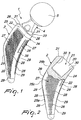
Figure 1 is a perspective view of a modular prosthetic device according to the invention; -
Figure 2 is a sectional front view of the upper part of a stem of the modular prosthetic device according to the invention; -
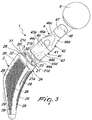
Figure 3 is an exploded perspective view of the modular prosthetic device according to the invention; -
Figure 4 is a perspective view of a femur with which a first embodiment of a device for determining the level of resection of the neck of the femur is associated; -
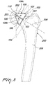
Figure 5 is a perspective view of a femur with which a second embodiment of a device for determining the level of resection of the neck of the femur is associated. - With reference to the figures, the modular prosthetic device for hip joint replacement according to the invention, generally designated by the
reference numeral 1, comprises astem 2, which is inserted within the femoral canal shaped by the surgeon. - According to the invention, the
stem 2 comprises in an upward region acavity 20 which defines areceptacle 3 for accommodating thelower portion 40 of aneck element 4. - The
lower portion 40 of theneck element 4 is inserted within thecavity 20, forming a stable and safe mating. - More precisely, insertion occurs by pushing the
neck element 4 into thecavity 20; alower end face 41 of theneck element 4 and atransverse cross-section 21 of thecavity 20 have substantially identical shapes and dimensions, thus allowing, as a consequence of said insertion, relative contact betweenfirst walls 45 of theneck element 4 andsecond walls 30 of thecavity 20. This contact creates such a friction force as to ensure a stable and safe mating. - An
upper portion 42 of theneck element 4 is inserted within aspherical element 5, which defines the head of theprosthetic device 1 that is designed to be articulated within the acetabular cup (not shown in the accompanying drawings). - More precisely, the
stem 2 is defined by four faces: afront face 22, arear face 23, acentral face 24 and alateral face 25. - The
front face 22 and therear face 23 are substantially identical and are mutually arranged so as to be substantially parallel. More precisely, when thedevice 1 is inserted in the femur, thefront face 22 and therear face 23, being mutually parallel, are both parallel to a front plane. - The mutually facing ends of the
front face 21 and of therear face 23 are connected by thecentral face 24 and by thelateral face 25. More precisely, thecentral face 24 has a substantially arc-like longitudinal extension, which is curved in a regular and constant manner; thelateral face 25 instead has a longitudinal extension that comprises alower portion 25a and anupper portion 25b, which are straight or slightly inclined and are connected centrally by acurved region 25c. - The upper portion of the
central face 24 and of thelateral face 25 are mutually substantially symmetrical on the sagittal plane with respect to the individual into whom thedevice 1 is implanted. - The
lateral face 25 is provided, in an upper region, with aregion 31 that is inclined downwardly with respect to the plane of thetransverse cross-section 21 of thecavity 20. - The
central face 24 and thelateral face 25 have a substantially semielliptical, preferably semicirculartransverse profile 26. The fact that the semiellipticaltransverse profile 26 extends along the entire longitudinal path of thecentral face 24 and thelateral face 25 makes it possible to avoid excessive stresses on the neck of the femur and to minimize the risks of fracture. - Advantageously, the
front face 22, therear face 23, thecentral face 24 and thelateral face 25 have aporous surface 27. - More precisely, the
porous surface 27 comprises a plurality ofcircular recesses 28 and a plurality ofcylindrical protrusions 29, both of which are arranged in an orderly fashion on thesurface 27. - The
porous surface 27 is intended to facilitate osteointegration of thedevice 1 with the tissues of the femoral canal in which thestem 2 is implanted. - As already mentioned, the
neck element 4 comprises alower portion 40, which is inserted in thecavity 20 defined in thestem 2, and anupper portion 42, which is inserted at the plane that intersects thespherical element 5. - More precisely, the
lower portion 40 comprises twohemispherical bodies lower end face 41, whose shape and dimensions are substantially equal to those of thetransverse cross-section 21 d and 21c of thecavity 20. More particularly, thelower end face 41 comprises twofirst sides semicircular contours - In a substantially similar manner, the
cavity 20 comprises twofirst sides semicircular contours 21c and 21d (seeFigure 3 ). - Advantageously, the
bodies lower end face 41 expand gradually in a transverse direction so that they are slightly inclined outwardly; likewise, thecavity 20 that extends downwardly from thetransverse cross-section 21 can taper gradually in a transverse direction, so that thewalls 21d and 21c of thecavity 20 are slightly inclined inwardly. The mutual inclination of the walls of thebody 40 and of the walls of thecavity 20 makes it possible to increase mutual contact between said walls, thus facilitating a stable and effective mating. - The
upper portion 42 of theneck element 4 is defined by foursectors sectors lower portion 40, they move closer together until they are associated in an upward region with atubular element 47 that has a circularupper end face 48. Thetubular element 47 and theupper end face 48 of theneck element 4 are inserted within the opening defined on the flat face of thespherical element 5. - Both the
stem 2 and theneck element 4 are made of highly biocompatible materials, such as titanium alloys. Preferably, thestem 2 is provided starting from powders of the titanium alloy Ti6A14V. - Advantageously, the
stem 2 can be provided entirely by means of a technique for melting by an electron beam Ti6A14V of titanium alloy powders (better known as EBM, "Electron Beam Melting"). - As an alternative, the
stem 2 is provided by laser sintering of Ti6A14V titanium alloy powders. - More precisely, in the
prosthetic device 1 the anterior/posterior thicknesses vary, among the different sizes, substantially by a value comprised between 0.1 mm and 0.2 mm. - Moreover, in the
prosthetic device 1, the lateral-central dimension between thelargest stem 2 and thesmallest stem 2 varies in the proximal region by approximately 3 mm and in the distal region by approximately 11 mm. - Moreover, the
stem 2 of theprosthetic device 1 has distal lateral-central dimensions that vary from 9 mm to 20 mm depending on the size; with such dimensions, the stems do not touch the cortical regions of the femur. - In practice it has been found that the device according to the invention fully achieves the intended aim, since by providing separately and in a modular manner the neck element and the stem it is possible to separate the choice of the stem from the choice of the neck element, so that for each implant it is possible to select independently the best suited stem and neck element.
- For each implant in each patient it is possible to select the neck element and the stem that make it possible to optimize bone sparing, muscle tension, limb length, offset and any anterior/posterior version.
- More precisely, the fact that in the prosthetic device according to the invention the neck element and the stem are not provided as a single component but as two distinct components that can be mated stably allows the easy provision of prosthetic devices of different sizes and configurations simply by mating stems and neck elements having different shapes and sizes. Moreover, by doing so in practice the number of available combinations is increased; a given size of the stem can in fact mate with all sizes of the neck element.
- More particularly, the different sizes of the stems vary in terms of the size and shape of the four faces (anterior, posterior, central and lateral), while the cavity inside which the lower portion of the neck element is inserted is identical for all sizes.
- Likewise, the neck elements of the different sizes can have, according to the requirements, a different upper portion, both in terms of geometry and in terms of length and inclination; while the lower portion, which is inserted in the cavity of the stem, is the same for all sizes.
- Thanks to the use of the modular necks and by operating on the resection of the neck of the femur (while at the same time always respecting the principle of sparing the bone of the neck as much as possible), in critical cases it is possible to adapt the length of the saved bone to the requirements of press-fit.
- Parva stems have, with respect to traditional stems, even those that use modular necks, an additional adjustment possibility, which is the length of the resection of the neck of the femur.
- If press-fit with the lateral cortex of the femur requires a size that is not long enough to use all the spared bone, it is possible to perform a resection of part of the spared bone and use a longer neck.
- Although the modular
prosthetic device 1 according to the invention has been conceived in particular for the hip joint, it can in any case be used more generally for other joints in which there is a stem and a neck element. - Some known devices, as well as the modular
prosthetic device 1 according to the invention, make it possible to preserve the neck of thefemur 201, i.e., they avoid complete surgical removal of the neck of thefemur 201 prior to implantation. - However, currently commercially available devices that preserve the neck of the
femur 201 tend to alter the length of the limb. - In particular, in case of implantation of the modular
prosthetic device 1, in order to spare more bone of the neck of thefemur 201 without increasing the length of the limb, the surgeon must perform a resection of the neck of thefemur 201 at such a level that theshorter neck element 4 allows the center of thespherical element 5 mounted on theneck element 4 to coincide with thecenter 203 of the head of thefemur 202 of the patient prior to the operation. - For facilitating this operation, according to the invention a
device 100 for performing resection of the neck of thefemur 201, as shown inFigures 4 and5 , is provided. - The
device 100 comprises aplate 101, which can be associated with the center ofrotation 203 of the head of thefemur 202. Theplate 101 has at least onestraight side 102 for defining aresection line 103 that is substantially perpendicular to thelongitudinal direction 204 of the neck of thefemur 201. - The
resection line 103 defines aplane 104 for resection of the neck of thefemur 201 that is substantially perpendicular to the plane of extension of theplate 101 and to thelongitudinal direction 204 of the neck of thefemur 201. - Advantageously, the
plate 101 comprises centrally one ormore holes 105 whose shape and dimensions are such as to allow the passage through them of areference pivot 110, which is fixed on the center ofrotation 203 of the head of thefemur 202. - Advantageously, the
hole 106 and thereference pivot 110 can be mutually shaped so that the respective interlocking coupling automatically ensures correct alignment of thestraight side 102 with respect to thelongitudinal direction 204 of the neck of thefemur 201. - The
distance 106 between thehole 105, crossed by thereference pivot 110, and thestraight side 102 defines the portion of the neck of thefemur 201 that is removed. - In a first embodiment, shown in
Figure 4 , theplate 101 has acurved side 107 which is C-shaped, the ends of the C-shape being connected to the ends of thestraight side 102. In this first embodiment, theplate 101 covers completely the head of thefemur 202. - As an alternative, the
plate 101 can have a shape that does not cover completely the head of the femur 52. By way of non-limiting example, theplate 101 ofFigure 5 has two catheti 108c and 108b which are arranged so as to form a triangle with thestraight side 102. - In both embodiments, the ends of the
straight side 102 or of anyother sides - Operation of the
device 100 according to the invention for performing resection of the neck of the femur is as follows. - First of all, the surgeon determines, by means of known instruments and methods, the
center 203 of the head of thefemur 202 and inserts thereference pivot 110 therein. - The surgeon then locks the
device 100 on thefemur 200, fitting thehole 105 of theplate 101 of thedevice 100 on thereference pivot 110. - If the
hole 106 and thereference pivot 110 are not shaped complementary to allow automatically the correct alignment of thestraight side 102 with respect to thelongitudinal direction 204 of the neck of thefemur 201, the surgeon can adjust manually the orientation of theplate 101 so as to achieve said correct alignment. - At this point, the surgeon performs resection along the
resection plane 103 defined by thestraight side 102 and substantially at right angles to thelongitudinal direction 204 of the neck of thefemur 201. - Moreover, the surgeon, during the preparation of the
femur body 205 inside which thestem 2 is to be inserted, ensures that the proximal portion of the excavation provided inside thefemur body 205 reaches the height at which the resection of the neck of thefemur 201 has been performed. - In practice it has been found that the device according to the invention fully achieves the intended aim, since it makes it possible to define a resection plane along which resection of the neck of the femur is performed.
- Although the
device 100 according to the invention for determining the resection of the neck of the femur has been conceived in particular for resection of the neck of the femur, it can in any case be used more generally for the resection of bones of other joints (shoulder, elbow, etcetera). - The device thus conceived is susceptible of numerous modifications and variations, all of which are within the scope of the appended claims; all the details may further be replaced with other technically equivalent elements.
- In practice, the materials used, as well as the dimensions, may be any according to requirements and to the state of the art.
- Reference is made to Italian Patent Application No.
MI2010A001668 - Where technical features mentioned in any claim are followed by reference signs, those reference signs have been included for the sole purpose of increasing the intelligibility of the claims and accordingly such reference signs do not have any limiting effect on the interpretation of each element identified by way of example by such reference signs.
Claims (8)
- A modular prosthetic device (1) for hip joint replacement, comprising a stem (2) adapted to be inserted within the femur, a modular neck element (4) that comprises an upper portion (42) having in an upper region a tubular element (47) and a lower portion (40), and a spherical head (5), said modular neck element (4) being coupleable with its tubular element (47) provided in its upper region to said spherical head (5), and wherein said stem (2) and modular neck element (4) are constituted by two distinct components that can be stably mated upon selection thereof among a plurality of stems (2) and neck elements (4) having different shapes and sizes so as to provide prosthetic devices of different sizes and configurations,
said stem (2) comprising, in an upper region, a cavity (20) for the safe accommodation of the lower portion (40) of said neck element (4),
characterized in that said lower portion (40) of said neck elements (4) comprises two bodies (43, 43a) of substantially semicircular contours (44c, 44d) which extend starting from a lower end face (41) of said lower portion (401 and whose shape and dimensions are substantially equal to those of a transverse cross-section (21d, 21c) of said cavity (20),
and in that said lower end face (41) of said lower portion (40) comprises two first sides (44a, 44b) which are concave and mutually identical and are joined, at their respective ends, to said substantially semicircular contours (44c,44d) of said bodies, (43, 43a), said cavity (20) comprising two first sides (21a, 21b) which are convex and mutually identical and which are joined, at their respective ends, to second substantially semicircular contours (21c, 21d) of said cavity (20). - The device according to claim 1, characterized in that the transverse cross-section of said cavity (20) and the lower end face of said lower portion (40) of said neck element (4) have substantially identical shapes and dimensions.
- The device according to one or more of the preceding claims, characterized in that said neck element (4) is pushed within said cavity (20) of said stem (2) and is locked by the friction force that is created as a consequence of contact between first walls of said neck element (4) and second walls of said cavity (20).
- The device according to one or more of the preceding claims, characterized in that said stem (2) comprises a front face (22), a rear face (23), a central face (24) and a lateral face (25); said front face (22) and said rear face (23) being substantially identical and mutually parallel; the mutually facing ends of said front face (22) and of said rear face (23) being connected by said central face (24) and by said lateral face (25).
- The device according to one or more of the preceding claims, characterized in that said central face (24) and said lateral face (25) have a substantially semicircular transverse profile.
- The device according to one or more of the preceding claims, characterized in that at least one of said front face (22), said rear face (23), said central face (24) and said lateral face (25) has a porous surface in order for facilitating osteointegration.
- The device according to one or more of the preceding claims, characterized in that said stem (2) has distal dimensions comprised substantially between 8 mm and 22 mm so as to avoid contact with the cortical regions of the femur.
- The device according to one or more of the preceding claims, characterized in that said stem (2) has distal dimensions comprised substantially between 9 mm and 20 mm so as to avoid contact with the cortical regions of the femur.
Applications Claiming Priority (2)
| Application Number | Priority Date | Filing Date | Title |
|---|---|---|---|
| ITMI2010A001668A IT1401926B1 (en) | 2010-09-14 | 2010-09-14 | MODULAR PROSTHETIC DEVICE FOR THE REPLACEMENT OF THE HOOK ARTICLE. |
| PCT/EP2011/063195 WO2012034771A1 (en) | 2010-09-14 | 2011-08-01 | Modular prosthetic device for hip joint replacement |
Publications (2)
| Publication Number | Publication Date |
|---|---|
| EP2616010A1 EP2616010A1 (en) | 2013-07-24 |
| EP2616010B1 true EP2616010B1 (en) | 2017-04-12 |
Family
ID=43738895
Family Applications (1)
| Application Number | Title | Priority Date | Filing Date |
|---|---|---|---|
| EP11737971.9A Active EP2616010B1 (en) | 2010-09-14 | 2011-08-01 | Modular prosthetic device for hip joint replacement |
Country Status (4)
| Country | Link |
|---|---|
| US (1) | US20130173012A1 (en) |
| EP (1) | EP2616010B1 (en) |
| IT (1) | IT1401926B1 (en) |
| WO (1) | WO2012034771A1 (en) |
Families Citing this family (7)
| Publication number | Priority date | Publication date | Assignee | Title |
|---|---|---|---|---|
| CN108348341A (en) | 2015-09-30 | 2018-07-31 | D·P·柯万 | Hip joint prosthesis |
| US11406504B2 (en) * | 2016-06-12 | 2022-08-09 | Kambiz Behzadi | Mechanical assembly including exterior surface preparation |
| GB201705917D0 (en) | 2017-04-12 | 2017-05-24 | Davidson Craig | Femoral trialling kit and assembly |
| US11369492B2 (en) * | 2017-08-22 | 2022-06-28 | Depuy Ireland Unlimited Company | Trial neck |
| IT201800010188A1 (en) * | 2018-11-09 | 2020-05-09 | Adler Ortho S P A | Stem for hip prosthesis, with fixed or modular neck. |
| GB201905459D0 (en) | 2019-04-17 | 2019-05-29 | Depuy Ireland Ultd Co | Indexable femoral neck resection guide |
| IT202000002632A1 (en) * | 2020-02-11 | 2021-08-11 | Aldo Toni | Improved hip prosthetic stem. |
Family Cites Families (8)
| Publication number | Priority date | Publication date | Assignee | Title |
|---|---|---|---|---|
| FR2700947B1 (en) * | 1993-02-03 | 1995-03-17 | Daniel Noyer | Prosthetic femoral implant for dysplastic hip. |
| US8617242B2 (en) * | 2001-05-25 | 2013-12-31 | Conformis, Inc. | Implant device and method for manufacture |
| FR2767471B1 (en) * | 1997-08-25 | 2003-02-21 | Rech S Et De Fabrication S E R | FEMALE HIP PROSTHESIS ROD |
| US7323013B2 (en) * | 1998-04-14 | 2008-01-29 | Encore Medical Asset Corporation | Differential porosity prosthetic hip system |
| US6464728B1 (en) * | 1998-04-14 | 2002-10-15 | Ian P. Murray | Modular neck for femur replacement surgery |
| US7115143B1 (en) * | 1999-12-08 | 2006-10-03 | Sdgi Holdings, Inc. | Orthopedic implant surface configuration |
| US20040199260A1 (en) * | 2000-01-30 | 2004-10-07 | Pope Bill J. | Prosthetic joint component having at least one sintered polycrystalline diamond compact articulation surface and substrate surface topographical features in said polycrystalline diamond compact |
| US20080167723A1 (en) * | 2006-03-20 | 2008-07-10 | Zimmer, Inc. | Prosthetic hip implants |
-
2010
- 2010-09-14 IT ITMI2010A001668A patent/IT1401926B1/en active
-
2011
- 2011-08-01 US US13/822,996 patent/US20130173012A1/en not_active Abandoned
- 2011-08-01 WO PCT/EP2011/063195 patent/WO2012034771A1/en not_active Ceased
- 2011-08-01 EP EP11737971.9A patent/EP2616010B1/en active Active
Non-Patent Citations (1)
| Title |
|---|
| None * |
Also Published As
| Publication number | Publication date |
|---|---|
| US20130173012A1 (en) | 2013-07-04 |
| WO2012034771A1 (en) | 2012-03-22 |
| EP2616010A1 (en) | 2013-07-24 |
| IT1401926B1 (en) | 2013-08-28 |
| ITMI20101668A1 (en) | 2012-03-15 |
Similar Documents
| Publication | Publication Date | Title |
|---|---|---|
| KR101340861B1 (en) | Humeral component of a shoulder joint prosthesis | |
| EP2502605B1 (en) | Shoulder prosthesis | |
| US9867628B2 (en) | Device for extraction of prosthetic implants | |
| US20130173012A1 (en) | Modular prosthetic device for hip joint replacement | |
| US10842915B2 (en) | Hip implant | |
| EP3187152B1 (en) | Modular femoral prosthesis system for hip arthroplasty | |
| EP3419534A1 (en) | Shoulder arthroplasty implant system | |
| WO2004071310A1 (en) | Acetabular reamer | |
| JP6633841B2 (en) | Instrument to remove bone insert | |
| JP2018512230A (en) | Orthopedic instrument system and method for protecting a femoral stem taper | |
| CA2942523A1 (en) | Femoral hip stem | |
| EP1900344A2 (en) | Resurfacing femoral head component | |
| WO2019090022A1 (en) | Subtalar joint replacement device and arthroplasty method | |
| CA2622010A1 (en) | Blade-like stem of a hip joint prosthesis | |
| EP3838227B1 (en) | Cement retaining implant stem for permanent fixation | |
| ES2242490B1 (en) | PROTESICAL DEVICE. | |
| HK1181295A (en) | Hip implant | |
| HK1181295B (en) | Hip implant |
Legal Events
| Date | Code | Title | Description |
|---|---|---|---|
| PUAI | Public reference made under article 153(3) epc to a published international application that has entered the european phase |
Free format text: ORIGINAL CODE: 0009012 |
|
| 17P | Request for examination filed |
Effective date: 20130404 |
|
| AK | Designated contracting states |
Kind code of ref document: A1 Designated state(s): AL AT BE BG CH CY CZ DE DK EE ES FI FR GB GR HR HU IE IS IT LI LT LU LV MC MK MT NL NO PL PT RO RS SE SI SK SM TR |
|
| RIN1 | Information on inventor provided before grant (corrected) |
Inventor name: CREMASCOLI, PATRIZIO Inventor name: SCHIRALDI, MARCO Inventor name: RENZI BRIVIO, LODOVICO |
|
| DAX | Request for extension of the european patent (deleted) | ||
| 17Q | First examination report despatched |
Effective date: 20151211 |
|
| GRAP | Despatch of communication of intention to grant a patent |
Free format text: ORIGINAL CODE: EPIDOSNIGR1 |
|
| INTG | Intention to grant announced |
Effective date: 20161025 |
|
| GRAS | Grant fee paid |
Free format text: ORIGINAL CODE: EPIDOSNIGR3 |
|
| GRAA | (expected) grant |
Free format text: ORIGINAL CODE: 0009210 |
|
| AK | Designated contracting states |
Kind code of ref document: B1 Designated state(s): AL AT BE BG CH CY CZ DE DK EE ES FI FR GB GR HR HU IE IS IT LI LT LU LV MC MK MT NL NO PL PT RO RS SE SI SK SM TR |
|
| REG | Reference to a national code |
Ref country code: GB Ref legal event code: FG4D |
|
| REG | Reference to a national code |
Ref country code: CH Ref legal event code: EP |
|
| REG | Reference to a national code |
Ref country code: IE Ref legal event code: FG4D |
|
| REG | Reference to a national code |
Ref country code: AT Ref legal event code: REF Ref document number: 883106 Country of ref document: AT Kind code of ref document: T Effective date: 20170515 |
|
| REG | Reference to a national code |
Ref country code: DE Ref legal event code: R096 Ref document number: 602011036896 Country of ref document: DE |
|
| REG | Reference to a national code |
Ref country code: FR Ref legal event code: PLFP Year of fee payment: 7 |
|
| REG | Reference to a national code |
Ref country code: NL Ref legal event code: MP Effective date: 20170412 |
|
| REG | Reference to a national code |
Ref country code: LT Ref legal event code: MG4D |
|
| REG | Reference to a national code |
Ref country code: AT Ref legal event code: MK05 Ref document number: 883106 Country of ref document: AT Kind code of ref document: T Effective date: 20170412 |
|
| PG25 | Lapsed in a contracting state [announced via postgrant information from national office to epo] |
Ref country code: NL Free format text: LAPSE BECAUSE OF FAILURE TO SUBMIT A TRANSLATION OF THE DESCRIPTION OR TO PAY THE FEE WITHIN THE PRESCRIBED TIME-LIMIT Effective date: 20170412 |
|
| PG25 | Lapsed in a contracting state [announced via postgrant information from national office to epo] |
Ref country code: ES Free format text: LAPSE BECAUSE OF FAILURE TO SUBMIT A TRANSLATION OF THE DESCRIPTION OR TO PAY THE FEE WITHIN THE PRESCRIBED TIME-LIMIT Effective date: 20170412 Ref country code: HR Free format text: LAPSE BECAUSE OF FAILURE TO SUBMIT A TRANSLATION OF THE DESCRIPTION OR TO PAY THE FEE WITHIN THE PRESCRIBED TIME-LIMIT Effective date: 20170412 Ref country code: AT Free format text: LAPSE BECAUSE OF FAILURE TO SUBMIT A TRANSLATION OF THE DESCRIPTION OR TO PAY THE FEE WITHIN THE PRESCRIBED TIME-LIMIT Effective date: 20170412 Ref country code: LT Free format text: LAPSE BECAUSE OF FAILURE TO SUBMIT A TRANSLATION OF THE DESCRIPTION OR TO PAY THE FEE WITHIN THE PRESCRIBED TIME-LIMIT Effective date: 20170412 Ref country code: FI Free format text: LAPSE BECAUSE OF FAILURE TO SUBMIT A TRANSLATION OF THE DESCRIPTION OR TO PAY THE FEE WITHIN THE PRESCRIBED TIME-LIMIT Effective date: 20170412 Ref country code: GR Free format text: LAPSE BECAUSE OF FAILURE TO SUBMIT A TRANSLATION OF THE DESCRIPTION OR TO PAY THE FEE WITHIN THE PRESCRIBED TIME-LIMIT Effective date: 20170713 Ref country code: NO Free format text: LAPSE BECAUSE OF FAILURE TO SUBMIT A TRANSLATION OF THE DESCRIPTION OR TO PAY THE FEE WITHIN THE PRESCRIBED TIME-LIMIT Effective date: 20170712 |
|
| PG25 | Lapsed in a contracting state [announced via postgrant information from national office to epo] |
Ref country code: SE Free format text: LAPSE BECAUSE OF FAILURE TO SUBMIT A TRANSLATION OF THE DESCRIPTION OR TO PAY THE FEE WITHIN THE PRESCRIBED TIME-LIMIT Effective date: 20170412 Ref country code: BG Free format text: LAPSE BECAUSE OF FAILURE TO SUBMIT A TRANSLATION OF THE DESCRIPTION OR TO PAY THE FEE WITHIN THE PRESCRIBED TIME-LIMIT Effective date: 20170712 Ref country code: PL Free format text: LAPSE BECAUSE OF FAILURE TO SUBMIT A TRANSLATION OF THE DESCRIPTION OR TO PAY THE FEE WITHIN THE PRESCRIBED TIME-LIMIT Effective date: 20170412 Ref country code: LV Free format text: LAPSE BECAUSE OF FAILURE TO SUBMIT A TRANSLATION OF THE DESCRIPTION OR TO PAY THE FEE WITHIN THE PRESCRIBED TIME-LIMIT Effective date: 20170412 Ref country code: RS Free format text: LAPSE BECAUSE OF FAILURE TO SUBMIT A TRANSLATION OF THE DESCRIPTION OR TO PAY THE FEE WITHIN THE PRESCRIBED TIME-LIMIT Effective date: 20170412 Ref country code: IS Free format text: LAPSE BECAUSE OF FAILURE TO SUBMIT A TRANSLATION OF THE DESCRIPTION OR TO PAY THE FEE WITHIN THE PRESCRIBED TIME-LIMIT Effective date: 20170812 |
|
| REG | Reference to a national code |
Ref country code: DE Ref legal event code: R097 Ref document number: 602011036896 Country of ref document: DE |
|
| PG25 | Lapsed in a contracting state [announced via postgrant information from national office to epo] |
Ref country code: CZ Free format text: LAPSE BECAUSE OF FAILURE TO SUBMIT A TRANSLATION OF THE DESCRIPTION OR TO PAY THE FEE WITHIN THE PRESCRIBED TIME-LIMIT Effective date: 20170412 Ref country code: RO Free format text: LAPSE BECAUSE OF FAILURE TO SUBMIT A TRANSLATION OF THE DESCRIPTION OR TO PAY THE FEE WITHIN THE PRESCRIBED TIME-LIMIT Effective date: 20170412 Ref country code: SK Free format text: LAPSE BECAUSE OF FAILURE TO SUBMIT A TRANSLATION OF THE DESCRIPTION OR TO PAY THE FEE WITHIN THE PRESCRIBED TIME-LIMIT Effective date: 20170412 Ref country code: EE Free format text: LAPSE BECAUSE OF FAILURE TO SUBMIT A TRANSLATION OF THE DESCRIPTION OR TO PAY THE FEE WITHIN THE PRESCRIBED TIME-LIMIT Effective date: 20170412 Ref country code: DK Free format text: LAPSE BECAUSE OF FAILURE TO SUBMIT A TRANSLATION OF THE DESCRIPTION OR TO PAY THE FEE WITHIN THE PRESCRIBED TIME-LIMIT Effective date: 20170412 |
|
| PLBE | No opposition filed within time limit |
Free format text: ORIGINAL CODE: 0009261 |
|
| STAA | Information on the status of an ep patent application or granted ep patent |
Free format text: STATUS: NO OPPOSITION FILED WITHIN TIME LIMIT |
|
| PG25 | Lapsed in a contracting state [announced via postgrant information from national office to epo] |
Ref country code: SM Free format text: LAPSE BECAUSE OF FAILURE TO SUBMIT A TRANSLATION OF THE DESCRIPTION OR TO PAY THE FEE WITHIN THE PRESCRIBED TIME-LIMIT Effective date: 20170412 |
|
| 26N | No opposition filed |
Effective date: 20180115 |
|
| REG | Reference to a national code |
Ref country code: CH Ref legal event code: PL |
|
| PG25 | Lapsed in a contracting state [announced via postgrant information from national office to epo] |
Ref country code: MC Free format text: LAPSE BECAUSE OF FAILURE TO SUBMIT A TRANSLATION OF THE DESCRIPTION OR TO PAY THE FEE WITHIN THE PRESCRIBED TIME-LIMIT Effective date: 20170412 |
|
| GBPC | Gb: european patent ceased through non-payment of renewal fee |
Effective date: 20170801 |
|
| PG25 | Lapsed in a contracting state [announced via postgrant information from national office to epo] |
Ref country code: LI Free format text: LAPSE BECAUSE OF NON-PAYMENT OF DUE FEES Effective date: 20170831 Ref country code: CH Free format text: LAPSE BECAUSE OF NON-PAYMENT OF DUE FEES Effective date: 20170831 |
|
| REG | Reference to a national code |
Ref country code: IE Ref legal event code: MM4A |
|
| PG25 | Lapsed in a contracting state [announced via postgrant information from national office to epo] |
Ref country code: SI Free format text: LAPSE BECAUSE OF FAILURE TO SUBMIT A TRANSLATION OF THE DESCRIPTION OR TO PAY THE FEE WITHIN THE PRESCRIBED TIME-LIMIT Effective date: 20170412 |
|
| REG | Reference to a national code |
Ref country code: BE Ref legal event code: MM Effective date: 20170831 |
|
| PG25 | Lapsed in a contracting state [announced via postgrant information from national office to epo] |
Ref country code: LU Free format text: LAPSE BECAUSE OF NON-PAYMENT OF DUE FEES Effective date: 20170801 |
|
| REG | Reference to a national code |
Ref country code: FR Ref legal event code: PLFP Year of fee payment: 8 |
|
| PG25 | Lapsed in a contracting state [announced via postgrant information from national office to epo] |
Ref country code: GB Free format text: LAPSE BECAUSE OF NON-PAYMENT OF DUE FEES Effective date: 20170801 Ref country code: IE Free format text: LAPSE BECAUSE OF NON-PAYMENT OF DUE FEES Effective date: 20170801 |
|
| PG25 | Lapsed in a contracting state [announced via postgrant information from national office to epo] |
Ref country code: BE Free format text: LAPSE BECAUSE OF NON-PAYMENT OF DUE FEES Effective date: 20170831 |
|
| PG25 | Lapsed in a contracting state [announced via postgrant information from national office to epo] |
Ref country code: MT Free format text: LAPSE BECAUSE OF NON-PAYMENT OF DUE FEES Effective date: 20170801 |
|
| PG25 | Lapsed in a contracting state [announced via postgrant information from national office to epo] |
Ref country code: HU Free format text: LAPSE BECAUSE OF FAILURE TO SUBMIT A TRANSLATION OF THE DESCRIPTION OR TO PAY THE FEE WITHIN THE PRESCRIBED TIME-LIMIT; INVALID AB INITIO Effective date: 20110801 |
|
| PG25 | Lapsed in a contracting state [announced via postgrant information from national office to epo] |
Ref country code: CY Free format text: LAPSE BECAUSE OF NON-PAYMENT OF DUE FEES Effective date: 20170412 |
|
| PG25 | Lapsed in a contracting state [announced via postgrant information from national office to epo] |
Ref country code: MK Free format text: LAPSE BECAUSE OF FAILURE TO SUBMIT A TRANSLATION OF THE DESCRIPTION OR TO PAY THE FEE WITHIN THE PRESCRIBED TIME-LIMIT Effective date: 20170412 |
|
| PG25 | Lapsed in a contracting state [announced via postgrant information from national office to epo] |
Ref country code: TR Free format text: LAPSE BECAUSE OF FAILURE TO SUBMIT A TRANSLATION OF THE DESCRIPTION OR TO PAY THE FEE WITHIN THE PRESCRIBED TIME-LIMIT Effective date: 20170412 |
|
| PG25 | Lapsed in a contracting state [announced via postgrant information from national office to epo] |
Ref country code: PT Free format text: LAPSE BECAUSE OF FAILURE TO SUBMIT A TRANSLATION OF THE DESCRIPTION OR TO PAY THE FEE WITHIN THE PRESCRIBED TIME-LIMIT Effective date: 20170412 |
|
| PG25 | Lapsed in a contracting state [announced via postgrant information from national office to epo] |
Ref country code: AL Free format text: LAPSE BECAUSE OF FAILURE TO SUBMIT A TRANSLATION OF THE DESCRIPTION OR TO PAY THE FEE WITHIN THE PRESCRIBED TIME-LIMIT Effective date: 20170412 |
|
| PGFP | Annual fee paid to national office [announced via postgrant information from national office to epo] |
Ref country code: FR Payment date: 20210625 Year of fee payment: 11 |
|
| PGFP | Annual fee paid to national office [announced via postgrant information from national office to epo] |
Ref country code: DE Payment date: 20210727 Year of fee payment: 11 |
|
| REG | Reference to a national code |
Ref country code: DE Ref legal event code: R082 Ref document number: 602011036896 Country of ref document: DE Representative=s name: SCHIEBER - FARAGO PATENTANWAELTE, DE Ref country code: DE Ref legal event code: R082 Ref document number: 602011036896 Country of ref document: DE Representative=s name: FARAGO PATENTANWALTSGESELLSCHAFT MBH, DE |
|
| REG | Reference to a national code |
Ref country code: DE Ref legal event code: R082 Ref document number: 602011036896 Country of ref document: DE Representative=s name: SCHIEBER - FARAGO PATENTANWAELTE, DE |
|
| REG | Reference to a national code |
Ref country code: DE Ref legal event code: R119 Ref document number: 602011036896 Country of ref document: DE |
|
| P01 | Opt-out of the competence of the unified patent court (upc) registered |
Effective date: 20230529 |
|
| PG25 | Lapsed in a contracting state [announced via postgrant information from national office to epo] |
Ref country code: FR Free format text: LAPSE BECAUSE OF NON-PAYMENT OF DUE FEES Effective date: 20220831 Ref country code: DE Free format text: LAPSE BECAUSE OF NON-PAYMENT OF DUE FEES Effective date: 20230301 |
|
| PGFP | Annual fee paid to national office [announced via postgrant information from national office to epo] |
Ref country code: IT Payment date: 20250620 Year of fee payment: 15 |