EP2615584A1 - Device for weighing flat objects in motion - Google Patents
Device for weighing flat objects in motion Download PDFInfo
- Publication number
- EP2615584A1 EP2615584A1 EP12170317.7A EP12170317A EP2615584A1 EP 2615584 A1 EP2615584 A1 EP 2615584A1 EP 12170317 A EP12170317 A EP 12170317A EP 2615584 A1 EP2615584 A1 EP 2615584A1
- Authority
- EP
- European Patent Office
- Prior art keywords
- conveyor
- attached
- spring
- weighing
- flat objects
- Prior art date
- Legal status (The legal status is an assumption and is not a legal conclusion. Google has not performed a legal analysis and makes no representation as to the accuracy of the status listed.)
- Granted
Links
- 238000005303 weighing Methods 0.000 title claims abstract description 62
- 230000035939 shock Effects 0.000 claims description 6
- 230000007246 mechanism Effects 0.000 description 4
- 238000000034 method Methods 0.000 description 4
- 230000008569 process Effects 0.000 description 4
- 230000009471 action Effects 0.000 description 1
- 238000004364 calculation method Methods 0.000 description 1
- 230000008859 change Effects 0.000 description 1
- 238000010276 construction Methods 0.000 description 1
- 230000002950 deficient Effects 0.000 description 1
- 230000001627 detrimental effect Effects 0.000 description 1
- 230000000694 effects Effects 0.000 description 1
- 230000005484 gravity Effects 0.000 description 1
- 238000012886 linear function Methods 0.000 description 1
- 238000012986 modification Methods 0.000 description 1
- 230000004048 modification Effects 0.000 description 1
- 230000003287 optical effect Effects 0.000 description 1
- 238000011144 upstream manufacturing Methods 0.000 description 1
Images

Classifications
-
- G—PHYSICS
- G01—MEASURING; TESTING
- G01G—WEIGHING
- G01G19/00—Weighing apparatus or methods adapted for special purposes not provided for in the preceding groups
-
- G—PHYSICS
- G01—MEASURING; TESTING
- G01G—WEIGHING
- G01G19/00—Weighing apparatus or methods adapted for special purposes not provided for in the preceding groups
- G01G19/002—Weighing apparatus or methods adapted for special purposes not provided for in the preceding groups for postal parcels and letters
- G01G19/005—Weighing apparatus or methods adapted for special purposes not provided for in the preceding groups for postal parcels and letters with electric or electronic computing means
-
- G—PHYSICS
- G07—CHECKING-DEVICES
- G07B—TICKET-ISSUING APPARATUS; FARE-REGISTERING APPARATUS; FRANKING APPARATUS
- G07B17/00—Franking apparatus
- G07B17/00459—Details relating to mailpieces in a franking system
- G07B17/00661—Sensing or measuring mailpieces
-
- G—PHYSICS
- G07—CHECKING-DEVICES
- G07B—TICKET-ISSUING APPARATUS; FARE-REGISTERING APPARATUS; FRANKING APPARATUS
- G07B17/00—Franking apparatus
- G07B17/00459—Details relating to mailpieces in a franking system
- G07B17/00467—Transporting mailpieces
-
- G—PHYSICS
- G07—CHECKING-DEVICES
- G07B—TICKET-ISSUING APPARATUS; FARE-REGISTERING APPARATUS; FRANKING APPARATUS
- G07B17/00—Franking apparatus
- G07B17/00459—Details relating to mailpieces in a franking system
- G07B17/00661—Sensing or measuring mailpieces
- G07B2017/00701—Measuring the weight of mailpieces
Definitions
- the present invention relates to a device for weighing items in motion. More specifically, it relates to the weighing of envelopes when travelling across a franking machine, in order to apply the correct rate.
- Postage rates depend on various parameters such as service level, delivery address, dimensions and weight. Post offices have defined rate tables associating notably the weight of letters with the corresponding charges. Although the rate varies by increments, it is necessary to measure the weight accurately. Notably, it must be determined with an accuracy of +/-1g if the weight is close to a value where the rate will change. Therefore franking machines are often associated or connected with a scale. Whenever one has to send a large number of letters per day, it becomes unpractical to weigh them manually. The franking machine may then include a dynamic scale as in US2011/147095 for example, so that the letters one by one are weighed in motion without slowing the franking process.
- Dynamic scales are usually composed of a conveyor and a load cell.
- the whole conveyor including motor, pulleys and belts, is supported by the load cell and the letter is transported at the same speed than in other parts of the franking machine, like for instance a printing station or a feeding module.
- Optical sensors are disposed before and after the conveyor.
- the weighing system is activated once a letter has been detected by a first sensor.
- the franking machine determines a time window wherein the letter is entirely supported by the conveyor.
- the gap between two subsequent letters must be large enough to ensure that only one will be weighed at a time.
- the weight is measured only after the first sensor has detected the trailing edge of the letter, and a second sensor has indicated that the previous letter has left the dynamic scale. By comparing the weight of the empty conveyor and the conveyor plus the letter, the weight of the letter can be calculated by difference.
- rollers or flexible flaps are added to the conveyor in order to press the letter against the belt while it is travelling. Those rollers or flaps form part of the conveyor and are weighted altogether.
- the dynamic scale is usually followed by the printing station where a postal indicium is printed on the letter after the postage charge has been calculated.
- the letter is pressed against a printing plate by a movable drive mechanism, in order to keep a constant distance between the letter and the printhead.
- the friction between the letter and the reference printing plate shall be low enough not to damage the letter.
- the printing process may also require a constant speed.
- the movable drive mechanism usually comprises a combination of arms and springs, pulleys and belts, and a motor.
- Franking machines can process letters of various thicknesses, typically 0.5 mm for postcards up to 20 mm. Therefore the drive mechanisms of the dynamic scale and the printing station are designed to operate within that range. It shall be noted that the reference side of the letter changes from the bottom (in the dynamic scale) to the top (in the printing station) and the transfer of a letter from the dynamic scale to the printing station may cause shocks and vibrations detrimental to the printing process.
- the dynamic scale is a complex and costly part of the franking machine because the load cell supports the complete conveyor, which is often heavier than the letters to be weighed. Moreover the rollers or flaps may generate shocks when bouncing on the letter. The motor, pulleys and belt may also generate vibrations. These shocks and vibrations complicate the measure of the weight. In practice they often limit the throughput of the system.
- the present invention solves the above problems by providing a different arrangement of the dynamic scale.
- the load cell weighing sensor
- the load cell is affixed to a weighing plate located above the envelope transport path.
- the envelope is pressed against the weighing plate by a movable drive mechanism as in the printing station.
- the applied load is big enough to ensure contact between the conveyor and the weighing plate whatever the weight of the actual envelope. Additionally, this load also compensates the weight of the weighing plate so that the load cell is constantly or sensibly constant loaded.
- a new device for weighing flat objects in motion comprises a conveyor for conveying the flat objects along an transport path, a weighing plate facing said transport path and comprising a set of free rollers for receiving the flat objects, and a weighing sensor attached to the weighing plate for measuring the weight of the flat objects, wherein the weighing sensor is arranged above the transport path and the conveyor is adapted to move vertically in order to press the flat objects in motion against the weighing plate.
- the conveyor is adapted to further apply a load which is constant or sensibly constant (depending on the selected implementation) regardless of the thickness of the flat object.
- the weighing plate comprises a set of free rollers which facing the conveyor belt in order to minimize the friction between the envelope in motion and the weighing plate.
- the load applied by the conveyor is obtained by a balance system comprising at least one lever arm attached at its upper end to the conveyor by a first pivot connection and attached at its lower end to a counterweight, said at least one lever arm being adaptable to rotate around at least a second pivot connection attached to a chassis of the device and attached to the at least one lever arm between its upper and lower ends.
- the load applied by the conveyor is obtained by a spring system comprising at least one lever arm attached by its lower end to a chassis of the device by a second pivot connection and attached to the upper end to the conveyor by a first pivot connection, and at least one spring attached to the chassis of the device and pushing the conveyor vertically in the upper direction.
- the spring has a tensile elongation at least equal to the length of the horizontal projection of said at least one lever arm and a coefficient of stiffness of at least 0.5 N/mm and typically 1 N/mm.
- the spring can be a tension spring attached at its lower end to the chassis of the device and at its upper end to one end of at least a traction cable running around at least one pulley and the other end of said at least one traction cable is connected to the upper end of said at least one lever arm or a spiral spring attached at its central end to the chassis of the device, the other end of said at least one spiral spring being attached to the upper end of said at least one lever arm.
- a dashpot is placed under the transport path in order to reduce the shocks and vibrations due to the passage of the flat objects on the transport path.
- the invention also concerns a mail machine comprising a device for weighing flat objects, particularly envelopes, in motion as described above.
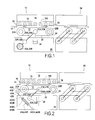
- Figure 1 illustrates a first embodiment of the device for weighing flat objects in motion according to the invention.
- the device 10 for weighing flat objects in motion comprises: a vertically movable conveyor 12 for conveying the mail items along a transport path 14, a weighing plate 16 disposed above the transport path 14 for receiving the mail items in motion, and a weighing sensor 18 attached to the weighing plate 16 and also disposed above the transport path 14.
- the weighing plate 16 comprises a set of free rollers 160 facing the conveyor 12.
- the conveyor comprises at least a conveyor belt 20, driven by upstream and downstream drive rollers 22A, 22B engaged with a motor 24.
- the conveyor 12 is vertically movable (i;e moves against the gravity) in the frame (or chassis 26) of the device through at least first pivot connection 27A, 27B attached to at least a counterweight 30A, 30B via at least a lever arm 28A, 28B. More particularly, the upper ends of two lever arms 28A, 28B are attached on each side of the conveyor 12, sensibly midway between the rollers 22A, 22B. The other ends of the two lever arms 28A, 28B are each attached to the counterweight 30A, 30B.
- the two lever arms 28A, 28B are attached to the chassis 26 of the device by a second pivot connection 32A, 32B disposed between the counterweight 30A, 30B and the first pivot connection 27A, 27B.
- An input presence sensor 34 and an exit presence sensor 36 are located in front and in back of the conveyor (or the weighing plate), respectively, to detect the presence of the mail item on the conveyor in order to start the acquisition of the weight of the mail item by the weight sensor 18.
- the counterweight 30A, 30B, through the lever arm 28A, 28B created by the pivot connections 27A, 27B, have the effect of pushing the conveyor 12 against the weighing plate 16 and apply a force at least equal to the weight of the heaviest mail item to weigh (about 1.5 kg).
- a dashpot 38 is placed between the conveyor 12 and the chassis 26 of the device for reducing shocks and vibrations induced by the successive passage in the transport path 14 of thin and thick mail items between the conveyor 12 and the weighing plate 16.
- the above device operates as follows. At rest, during an initialization phase of the device, the conveyor 12 is in contact with the weighing plate 16 via the set of free rollers 160 and thus maintains a constant load on the weighing plate greater than the weight of the heaviest mail item to weigh (about 1.5 kg). As the belt 20 is in touch with the set of free rollers, the horizontal effort between the conveyor and the plate is sensibly null. This constant load applied by the conveyor at rest is measured by the weight sensor 18 and is used as a tare so that when no mail item is present in the transport path 14, the weight sensor measures a null weight. When a mail item comes in front of the device, the conveyor belt 20 and its drive rollers 22A, 22B drive the mail item toward the printing station 50.
- the conveyor 12 presses the mail item against the weighing plate 16 via the set of free rollers 160.
- the load applied by the conveyor is ensured by the counterweights 30A, 30B through the lever formed by the lever arms 28A and 28B and the second pivot connections 32A, 32B which push vertically the conveyor 12 toward the weighing plate 16.
- the input presence sensor 34 no longer detects the presence of the mail item, the acquisition of the weight of the mail item by the weight sensor 18 can begin and will be done until the mail item reaches the exit presence sensor 36.
- the weight sensor acquire several samples of the weight of the mail item before applying a filter function to all acquired samples.
- the applied function can simply be an average of the samples or can be more sophisticated as it is known in the art.
- Precision bearings can be used for the two pivot connections so that no unwanted torque is transmitted to the arms.
- the torque generated by the motor which may vary according to the weight of the mail item is not transmitted.
- the counterweight is only balanced by the reaction of the weighing plate, and the load is independent of the thickness of the mail item.
- the horizontal effort applied to the weighing plate 16 is the same with or without a mail item and is anyway sensibly null.
- Figure 2 illustrates a second embodiment of the device for weighing flat objects in motion according to the invention.
- the balance system formed by the lever arms 28A, 28B, the counterweights 30A, 30B and the second pivot connection 32A, 32B (allowing the conveyor 12 to maintain a constant load applied to the weighing plate 16 via the set of free rollers 160) is replaced by a tension spring system composed of traction cables, tension springs and pulleys, which do not maintain a constant load but a sensibly constant load only.
- the conveyor 12 comprises at least the conveyor belt 20 driven by the drive rollers 22A, 22B connected to the motor 24.
- the conveyor 12 is vertically movable in the frame (or chassis 26) of the device through at least first pivot connection 27A, 27B and at least a lever arm 28A, 28B. More particularly, the upper ends of two lever arms 28A, 28B are attached by two pivot connections 27A, 27B on each side of the conveyor 12, sensibly midway between the rollers 22A, 22B. The other ends of the two lever arms are attached to the chassis 26 of the device by a second pivot connection 32A, 32B. In this second embodiment, the upper ends of the two lever arms are also attached to the upper ends 400A, 400B of traction cables 40A, 40B.
- the tension springs 44A, 44B are connected by their lower end 442A, 442B to the chassis 26 of the device.
- the pulley 42A, 42B are mounted free in rotation on the chassis 26 of the device.
- the tension springs 44A, 44B are mounted elongated so that when the device is at rest ( ie. no mail item on the transport path 14), the springs are elongated.
- the device operates as in the first embodiment except the following steps.
- the sensibly constant load applied by the conveyor 12 is now provided by the combined action of traction cables 40A, 40B, pulleys 42A 42B, springs 44A, 44B, and two lever arms 28A and 28B.
- the lever arms 28A, 28B By rotating around the pivot connection 32A and 32B, the lever arms 28A, 28B cause the lowering of the conveyor 12 and the elongation of the springs 44A and 447B through the traction cables 40A, 40B and pulleys 42A, 42B.
- the calibration of the spring is critical. Indeed, a defective calibration will imply a non-constant (variable) load.
- Figure 3 illustrates the different forces that permit this calibration of the load spring in the tension spring system of figure 2 .
- the wire is horizontal when an envelope 19 mm thick is in the scale (this is close to the maximum thickness).
- the lever arm moves up when no envelope is in the scale but its vertically projected length H remains sensibly the same.
- the load spring is chosen so that its elongation is close to the horizontally projected length of the arm D. Then the torque applied on the lever arm by the spring is sensibly proportional to this length.
- the spring is chosen with an elongation E of 117 mm when there is no envelope in the transport path.
- the load effort is 20.0698 N when there is no envelope and 20.0729 N with an envelope 19 mm thick.
- the difference is 0.0036 N or 0.36 grams.
- H, D and the elongation are quasi-linear functions of ⁇ in the considered interval, it can be easily verified that all intermediate values of the load are in the same range.
- the spring shall not only support the envelope but also the whole conveyor including frame, motor pulleys and belts, and furthermore balance the weight of the weighing plate.
- the stiffness of the spring is more likely to be in the range of 1 N/mm so that the load cell is sensibly constantly loaded. In this case the load difference between thin and thick envelopes increases but remains below one gram in conformity with the postal requirements.
- Figure 4 illustrates a third embodiment of the device for weighing flat objects in motion according to the invention.
- the tension spring 44A, 44B and the pulley 42A, 42B of the second embodiment are replaced by a spiral spring 46A, 46B and the traction cable 40A, 40B is no longer useful.
- the conveyor 12 comprises at least a conveyor belt 20 driven by the drive rollers 22A, 22B engaged with a motor 24.
- the conveyor 12 is vertically movable in the frame (or chassis 26) of the device through at least first pivot connection 27A, 27B and at least a lever arm 28A, 28B.
- the upper ends of the two lever arms 28A, 28B are attached by a first pivot connection 27A, 27B on each side of the conveyor 12, sensibly midway between the drive rollers 22A, 22B.
- the other ends of lever arms are attached to the chassis 26 of the device via a second pivot connection 32A, 32B.
- spiral springs 46A, 46B are attached by their central end 460A, 460B to the chassis 26 (for instance in place of the pulley 42A, 42B of the second embodiment), the other ends 462A, 462B of the spiral spring 46A, 46B are attached to the upper ends of the two lever arms 28A, 28B.
- the spiral spring 46A, 46B is mounted elongated so that when the device is at rest ( ie. no mail item on the transport path 14), the springs are elongated.
- the spiral spring will apply a momentum M /oz to the chassis equal to k 0 ⁇ , where k 0 is the angular stiffness and ⁇ is the angular deformation.
- the momentum M /oz is equal to T*r where r is the external radius of the spring and the linear elongation of the spring E is equal to r* ⁇ .
- the tension T is equal to k 0 *E/r 2 .
- the spiral spring is chosen so that its external radius remains sensibly constant between the upper and lower positions of the arm so T remains sensibly proportional to E as in the previous embodiment.
- the device for weighing flat objects can also include an access ramp to transfer the mail item to the weighing plate.
- the access ramp can have two drive rollers and a conveyor belt, the lower part of which is at the height of the transport path of the feeding area while the top is at the height of the weighing plate.
- a sensibly constant load (and a fortiori a constant load) whatever is the thickness of the envelope is not an absolute requirement of the system.
- franking machines - and notably the ones having dynamic scales - are equipped with thickness sensors. Then it is possible to tabulate the load in function of thickness and to apply the appropriate correction.
- a constant or sensibly constant load is preferable to variable load in order to simplify the calculation of the weight.
Landscapes
- Physics & Mathematics (AREA)
- General Physics & Mathematics (AREA)
- Mathematical Physics (AREA)
- Devices For Checking Fares Or Tickets At Control Points (AREA)
- Sorting Of Articles (AREA)
Abstract
Description
- The present invention relates to a device for weighing items in motion. More specifically, it relates to the weighing of envelopes when travelling across a franking machine, in order to apply the correct rate.
- Postage rates depend on various parameters such as service level, delivery address, dimensions and weight. Post offices have defined rate tables associating notably the weight of letters with the corresponding charges. Although the rate varies by increments, it is necessary to measure the weight accurately. Notably, it must be determined with an accuracy of +/-1g if the weight is close to a value where the rate will change. Therefore franking machines are often associated or connected with a scale. Whenever one has to send a large number of letters per day, it becomes unpractical to weigh them manually. The franking machine may then include a dynamic scale as in
US2011/147095 for example, so that the letters one by one are weighed in motion without slowing the franking process. - Dynamic scales are usually composed of a conveyor and a load cell. The whole conveyor, including motor, pulleys and belts, is supported by the load cell and the letter is transported at the same speed than in other parts of the franking machine, like for instance a printing station or a feeding module.
- Optical sensors are disposed before and after the conveyor. The weighing system is activated once a letter has been detected by a first sensor. Depending on the speed of the conveyor, the franking machine determines a time window wherein the letter is entirely supported by the conveyor. The gap between two subsequent letters must be large enough to ensure that only one will be weighed at a time. The weight is measured only after the first sensor has detected the trailing edge of the letter, and a second sensor has indicated that the previous letter has left the dynamic scale. By comparing the weight of the empty conveyor and the conveyor plus the letter, the weight of the letter can be calculated by difference.
- To make sure that the letter travels at a consistent speed, there shall be no slippage between the letter and the conveying belt. Rollers or flexible flaps are added to the conveyor in order to press the letter against the belt while it is travelling. Those rollers or flaps form part of the conveyor and are weighted altogether.
- The dynamic scale is usually followed by the printing station where a postal indicium is printed on the letter after the postage charge has been calculated. During this operation, the letter is pressed against a printing plate by a movable drive mechanism, in order to keep a constant distance between the letter and the printhead. The friction between the letter and the reference printing plate shall be low enough not to damage the letter. The printing process may also require a constant speed. The movable drive mechanism usually comprises a combination of arms and springs, pulleys and belts, and a motor.
- Franking machines can process letters of various thicknesses, typically 0.5 mm for postcards up to 20 mm. Therefore the drive mechanisms of the dynamic scale and the printing station are designed to operate within that range. It shall be noted that the reference side of the letter changes from the bottom (in the dynamic scale) to the top (in the printing station) and the transfer of a letter from the dynamic scale to the printing station may cause shocks and vibrations detrimental to the printing process.
- The dynamic scale is a complex and costly part of the franking machine because the load cell supports the complete conveyor, which is often heavier than the letters to be weighed. Moreover the rollers or flaps may generate shocks when bouncing on the letter. The motor, pulleys and belt may also generate vibrations. These shocks and vibrations complicate the measure of the weight. In practice they often limit the throughput of the system.
- The present invention solves the above problems by providing a different arrangement of the dynamic scale. Instead of supporting the conveyor, the load cell (weighing sensor) is affixed to a weighing plate located above the envelope transport path. The envelope is pressed against the weighing plate by a movable drive mechanism as in the printing station. The applied load is big enough to ensure contact between the conveyor and the weighing plate whatever the weight of the actual envelope. Additionally, this load also compensates the weight of the weighing plate so that the load cell is constantly or sensibly constant loaded.
- When an envelope travels through the scale, it is pressed against the weighing plate and its weight is subtracted from the load.
- To achieve this function a new device for weighing flat objects in motion comprises a conveyor for conveying the flat objects along an transport path, a weighing plate facing said transport path and comprising a set of free rollers for receiving the flat objects, and a weighing sensor attached to the weighing plate for measuring the weight of the flat objects, wherein the weighing sensor is arranged above the transport path and the conveyor is adapted to move vertically in order to press the flat objects in motion against the weighing plate. Preferably, the conveyor is adapted to further apply a load which is constant or sensibly constant (depending on the selected implementation) regardless of the thickness of the flat object. The weighing plate comprises a set of free rollers which facing the conveyor belt in order to minimize the friction between the envelope in motion and the weighing plate.
- In one embodiment, the load applied by the conveyor is obtained by a balance system comprising at least one lever arm attached at its upper end to the conveyor by a first pivot connection and attached at its lower end to a counterweight, said at least one lever arm being adaptable to rotate around at least a second pivot connection attached to a chassis of the device and attached to the at least one lever arm between its upper and lower ends.
- In another embodiment, the load applied by the conveyor is obtained by a spring system comprising at least one lever arm attached by its lower end to a chassis of the device by a second pivot connection and attached to the upper end to the conveyor by a first pivot connection, and at least one spring attached to the chassis of the device and pushing the conveyor vertically in the upper direction. Advantageously, the spring has a tensile elongation at least equal to the length of the horizontal projection of said at least one lever arm and a coefficient of stiffness of at least 0.5 N/mm and typically 1 N/mm.
- The spring can be a tension spring attached at its lower end to the chassis of the device and at its upper end to one end of at least a traction cable running around at least one pulley and the other end of said at least one traction cable is connected to the upper end of said at least one lever arm or a spiral spring attached at its central end to the chassis of the device, the other end of said at least one spiral spring being attached to the upper end of said at least one lever arm.
- Preferably, a dashpot is placed under the transport path in order to reduce the shocks and vibrations due to the passage of the flat objects on the transport path.
- The invention also concerns a mail machine comprising a device for weighing flat objects, particularly envelopes, in motion as described above.
- The actual construction, operation and advantages of the present invention will be better understood by referring to the following drawings in which like numerals identify like parts:
-
Figure 1 shows a schematic view of an implementation of the device for weighing flat objects in motion using a counterweight system to maintain a constant load of the transport path on the weighing sensor, -
Figure 2 shows a schematic view of another implementation of the device for weighing flat objects in motion using a tension spring system to maintain a sensibly constant load of the transport path on the weighing sensor, -
Figure 3 shows a schematic representation of efforts in the tension spring system, and -
Figure 4 shows a schematic view of still another implementation of the device for weighing flat objects in motion using a spiral spring system to maintain a sensibly constant load of the transport path on the weighing sensor. -
Figure 1 illustrates a first embodiment of the device for weighing flat objects in motion according to the invention. - In this first embodiment, the
device 10 for weighing flat objects in motion comprises: a verticallymovable conveyor 12 for conveying the mail items along atransport path 14, aweighing plate 16 disposed above thetransport path 14 for receiving the mail items in motion, and aweighing sensor 18 attached to theweighing plate 16 and also disposed above the transport path 14.Theweighing plate 16 comprises a set offree rollers 160 facing theconveyor 12. - The conveyor comprises at least a
conveyor belt 20, driven by upstream anddownstream drive rollers motor 24. Theconveyor 12 is vertically movable (i;e moves against the gravity) in the frame (or chassis 26) of the device through at leastfirst pivot connection counterweight lever arm lever arms conveyor 12, sensibly midway between therollers lever arms counterweight lever arms chassis 26 of the device by asecond pivot connection counterweight first pivot connection input presence sensor 34 and anexit presence sensor 36 are located in front and in back of the conveyor (or the weighing plate), respectively, to detect the presence of the mail item on the conveyor in order to start the acquisition of the weight of the mail item by theweight sensor 18. - The
counterweight lever arm pivot connections conveyor 12 against the weighingplate 16 and apply a force at least equal to the weight of the heaviest mail item to weigh (about 1.5 kg). Optionally, adashpot 38 is placed between theconveyor 12 and thechassis 26 of the device for reducing shocks and vibrations induced by the successive passage in thetransport path 14 of thin and thick mail items between theconveyor 12 and the weighingplate 16. - The above device operates as follows. At rest, during an initialization phase of the device, the
conveyor 12 is in contact with the weighingplate 16 via the set offree rollers 160 and thus maintains a constant load on the weighing plate greater than the weight of the heaviest mail item to weigh (about 1.5 kg). As thebelt 20 is in touch with the set of free rollers, the horizontal effort between the conveyor and the plate is sensibly null. This constant load applied by the conveyor at rest is measured by theweight sensor 18 and is used as a tare so that when no mail item is present in thetransport path 14, the weight sensor measures a null weight. When a mail item comes in front of the device, theconveyor belt 20 and itsdrive rollers printing station 50. During the moving of the mail item toward the printing station, theconveyor 12 presses the mail item against the weighingplate 16 via the set offree rollers 160. The load applied by the conveyor is ensured by thecounterweights lever arms second pivot connections conveyor 12 toward the weighingplate 16. When the mail item is fully supported by the conveyor, theinput presence sensor 34 no longer detects the presence of the mail item, the acquisition of the weight of the mail item by theweight sensor 18 can begin and will be done until the mail item reaches theexit presence sensor 36. To avoid errors related to instantaneous measures, the weight sensor acquire several samples of the weight of the mail item before applying a filter function to all acquired samples. The applied function can simply be an average of the samples or can be more sophisticated as it is known in the art. - Precision bearings can be used for the two pivot connections so that no unwanted torque is transmitted to the arms. Notably, the torque generated by the motor, which may vary according to the weight of the mail item is not transmitted. In these conditions the counterweight is only balanced by the reaction of the weighing plate, and the load is independent of the thickness of the mail item. The horizontal effort applied to the weighing
plate 16 is the same with or without a mail item and is anyway sensibly null. -
Figure 2 illustrates a second embodiment of the device for weighing flat objects in motion according to the invention. In this embodiment, the balance system formed by thelever arms counterweights second pivot connection conveyor 12 to maintain a constant load applied to the weighingplate 16 via the set of free rollers 160) is replaced by a tension spring system composed of traction cables, tension springs and pulleys, which do not maintain a constant load but a sensibly constant load only. As in the previous embodiment, theconveyor 12 comprises at least theconveyor belt 20 driven by thedrive rollers motor 24. Theconveyor 12 is vertically movable in the frame (or chassis 26) of the device through at leastfirst pivot connection lever arm lever arms pivot connections conveyor 12, sensibly midway between therollers chassis 26 of the device by asecond pivot connection traction cables traction cables lower ends lower end chassis 26 of the device. Thepulley chassis 26 of the device. - The tension springs 44A, 44B are mounted elongated so that when the device is at rest (ie. no mail item on the transport path 14), the springs are elongated.
- In this second embodiment, the device operates as in the first embodiment except the following steps. Indeed, the sensibly constant load applied by the
conveyor 12 is now provided by the combined action oftraction cables 42A 42B, springs 44A, 44B, and twolever arms pivot connection lever arms conveyor 12 and the elongation of thesprings 44A and 447B through thetraction cables conveyor 12 on the weighingplate 16 or on the mail item regardless of the thickness of the mail item, the calibration of the spring is critical. Indeed, a defective calibration will imply a non-constant (variable) load. -
Figure 3 illustrates the different forces that permit this calibration of the load spring in the tension spring system offigure 2 . The wire is horizontal when an envelope 19 mm thick is in the scale (this is close to the maximum thickness). In this case the lever arm moves up when no envelope is in the scale but its vertically projected length H remains sensibly the same. The load spring is chosen so that its elongation is close to the horizontally projected length of the arm D. Then the torque applied on the lever arm by the spring is sensibly proportional to this length. As the torque applied by the conveyor is also proportional to this length, the load is sensibly constant within the range of angular positions of the lever arm as follows:



- For instance, the spring is chosen with an elongation E of 117 mm when there is no envelope in the transport path.
- At θ0 corresponding to no envelope


- At θ19 corresponding to an envelope 19 mm thick


- With a stiffness k of 0.5 N/mm, the load effort is 20.0698 N when there is no envelope and 20.0729 N with an envelope 19 mm thick. The difference is 0.0036 N or 0.36 grams. As H, D and the elongation are quasi-linear functions of θ in the considered interval, it can be easily verified that all intermediate values of the load are in the same range.
- In practice the spring shall not only support the envelope but also the whole conveyor including frame, motor pulleys and belts, and furthermore balance the weight of the weighing plate. The stiffness of the spring is more likely to be in the range of 1 N/mm so that the load cell is sensibly constantly loaded. In this case the load difference between thin and thick envelopes increases but remains below one gram in conformity with the postal requirements.
-
Figure 4 illustrates a third embodiment of the device for weighing flat objects in motion according to the invention. In this embodiment, thetension spring pulley spiral spring traction cable plate 16 too. As in previous embodiments, theconveyor 12 comprises at least aconveyor belt 20 driven by thedrive rollers motor 24. Theconveyor 12 is vertically movable in the frame (or chassis 26) of the device through at leastfirst pivot connection lever arm lever arms first pivot connection conveyor 12, sensibly midway between thedrive rollers chassis 26 of the device via asecond pivot connection central end pulley spiral spring lever arms - The
spiral spring - The spiral spring will apply a momentum M/oz to the chassis equal to k0 α, where k0 is the angular stiffness and α is the angular deformation. The momentum M/oz is equal to T*r where r is the external radius of the spring and the linear elongation of the spring E is equal to r*α. Then the tension T is equal to k0*E/r2. The spiral spring is chosen so that its external radius remains sensibly constant between the upper and lower positions of the arm so T remains sensibly proportional to E as in the previous embodiment.
- While the invention has been described with reference to exemplary embodiments, it will be understood by those skilled in the art that various changes may be made and equivalents may be substituted for elements thereof without departing from the scope of the invention. For instance, all embodiment are described with two load application systems (arms and counterweights, arms and tension springs, arms and spiral springs), attached of each side of the conveyor, but it is clear for those skilled in the art that a single load application system attached to one side or the center of the conveyor path can be used. In addition, many modifications (other spring and non spring arrangements are possible to ensure at least a sensibly constant (and preferably a constant) load whatever the thickness of the envelope being weighed) may be made to adapt a particular situation or material to the teachings of the invention without departing from the essential scope thereof. For example, the device for weighing flat objects can also include an access ramp to transfer the mail item to the weighing plate. The access ramp can have two drive rollers and a conveyor belt, the lower part of which is at the height of the transport path of the feeding area while the top is at the height of the weighing plate.
- It shall be noted that a sensibly constant load (and a fortiori a constant load) whatever is the thickness of the envelope is not an absolute requirement of the system. As letter dimensions are required in order to calculate certain postage rates, franking machines - and notably the ones having dynamic scales - are equipped with thickness sensors. Then it is possible to tabulate the load in function of thickness and to apply the appropriate correction. However a constant or sensibly constant load is preferable to variable load in order to simplify the calculation of the weight.
- Therefore, it is intended that the invention not be limited to the particular embodiment disclosed as the best or only mode contemplated for carrying out this invention, but that the invention will include all embodiments falling within the scope of the appended claims. Also, in the drawings and the description, there have been disclosed exemplary embodiments of the invention and, although specific terms may have been employed, they are unless otherwise stated used in a generic and descriptive sense only and not for purposes of limitation, the scope of the invention therefore not being so limited. Moreover, the use of the terms first, second, etc. do not denote any order or importance, but rather the terms first, second, etc. are used to distinguish one element from another. Furthermore, the use of the terms a, an, etc. do not denote a limitation of quantity, but rather denote the presence of at least one of the referenced item.
Claims (13)
- Device for weighing flat objects in motion comprising a conveyor (12) for conveying the flat objects along a transport path (14), a weighing plate (16) facing said transport path and comprising a set of free rollers (160) for receiving the flat objects, and a weighing sensor (18) attached to the weighing plate for measuring the weight of the flat objects, wherein the weighing sensor is arranged above the transport path and the conveyor is adapted to move vertically in order to press the flat objects in motion against the weighing plate.
- Device according to claim 1, wherein the conveyor is adapted to further apply a load which is constant regardless of the thickness of the flat object.
- Device according to claim 1, wherein the conveyor is adapted to further apply a load which is sensibly constant regardless of the thickness of the flat object.
- Device according to claim 1, wherein the conveyor comprises at least one conveyor belt (20).
- Device according to claim 2, wherein the load applied by the conveyor is obtained by a balance system comprising at least one lever arm (28A, 28B) attached at its upper end to the conveyor by a first pivot connection (27A, 27B) and attached at its lower end to a counterweight (30A, 30B), said at least one lever arm being adapted to rotate around at least a second pivot connection (32A, 32B) attached to a chassis (26) of the device and attached to the at least one lever arm between its upper and lower ends.
- Device according to claim 1 or 3, wherein the load applied by the conveyor is obtained by a spring system comprising at least one lever arm (28A, 28B) attached at its lower end to a chassis (26) of the device by a second pivot connection (32A, 32B) and attached at the upper end to the conveyor by a first pivot connection (27A, 27B), and at least one spring (44A, 44B) attached to the chassis of the device and pushing the conveyor vertically in the upper direction.
- Device according to claim 6, wherein said at least one spring has a tensile elongation at least equal to the length of the horizontal projection of said at least one lever arm.
- Device according to claim 6, wherein said at least one spring has a stiffness coefficient of at least 0.5 N/mm and typically 1 N/mm.
- Device according to claim 6, wherein the spring is a tension spring (44A 44B) attached at its lower end to the chassis of the device and at its upper end to one end of at least a traction cable (40A, 40B) running around at least one pulley (42A, 42B) and the other end of said at least one traction cable is connected to the upper end of said at least one lever arm.
- Device according to claim 6, wherein the spring is a spiral spring (46A, 46B) attached at its central end to the chassis (26) of the device, the other end of said at least one spiral spring being attached to the upper end of said at least one lever arm.
- Device according to any one of claims 1 to 10, wherein a dashpot (38) is placed under the conveyor in order to reduce shocks and vibrations due to the passage of flat objects on the transport path.
- Device according to any one of claims 1 to 11, wherein the flat objects are envelopes.
- Mailing machine comprising a device for weighing envelopes in motion according to claim 12.
Priority Applications (3)
| Application Number | Priority Date | Filing Date | Title |
|---|---|---|---|
| EP12170317.7A EP2615584B1 (en) | 2012-01-10 | 2012-05-31 | Device for weighing flat objects in motion |
| US13/736,626 US9310241B2 (en) | 2012-01-10 | 2013-01-08 | Device for weighing flat objects in motion |
| US15/951,026 USRE48188E1 (en) | 2012-01-10 | 2018-04-11 | Device for weighing flat objects in motion |
Applications Claiming Priority (2)
| Application Number | Priority Date | Filing Date | Title |
|---|---|---|---|
| EP12305032 | 2012-01-10 | ||
| EP12170317.7A EP2615584B1 (en) | 2012-01-10 | 2012-05-31 | Device for weighing flat objects in motion |
Publications (2)
| Publication Number | Publication Date |
|---|---|
| EP2615584A1 true EP2615584A1 (en) | 2013-07-17 |
| EP2615584B1 EP2615584B1 (en) | 2018-08-01 |
Family
ID=46147373
Family Applications (1)
| Application Number | Title | Priority Date | Filing Date |
|---|---|---|---|
| EP12170317.7A Not-in-force EP2615584B1 (en) | 2012-01-10 | 2012-05-31 | Device for weighing flat objects in motion |
Country Status (2)
| Country | Link |
|---|---|
| US (2) | US9310241B2 (en) |
| EP (1) | EP2615584B1 (en) |
Cited By (1)
| Publication number | Priority date | Publication date | Assignee | Title |
|---|---|---|---|---|
| CN105865609A (en) * | 2016-06-20 | 2016-08-17 | 许昌市大力电机制造有限公司 | Automatic rapid weighing system |
Families Citing this family (3)
| Publication number | Priority date | Publication date | Assignee | Title |
|---|---|---|---|---|
| JP2011247697A (en) * | 2010-05-25 | 2011-12-08 | Toshiba Corp | Weight measuring apparatus of paper sheet, paper sheet processing apparatus including weight measuring apparatus, and weight measuring method of paper sheet |
| DE102015104693B4 (en) * | 2015-03-27 | 2017-06-29 | Sartorius Lab Instruments Gmbh & Co. Kg | Balance with load changer and method of operation |
| JP7304045B2 (en) * | 2018-03-20 | 2023-07-06 | 株式会社イシダ | Conveying device and combination weighing device equipped with it |
Citations (3)
| Publication number | Priority date | Publication date | Assignee | Title |
|---|---|---|---|---|
| US4705413A (en) * | 1986-07-18 | 1987-11-10 | Pitney Bowes Inc. | Thickness compensating means for mailing machine |
| EP2065686A1 (en) * | 2007-11-30 | 2009-06-03 | Pitney Bowes, Inc. | Parallel path weight measurement system for sheet handling devices |
| US20110147095A1 (en) * | 2009-12-17 | 2011-06-23 | Pitney Bowes Inc. | Mailing machine transport system with integral scale for weighing mail pieces |
Family Cites Families (18)
| Publication number | Priority date | Publication date | Assignee | Title |
|---|---|---|---|---|
| US1902512A (en) * | 1929-05-03 | 1933-03-21 | Swift & Co | Combination conveyer and scale |
| FR2140751A5 (en) * | 1971-06-07 | 1973-01-19 | Chenut Gabriel | |
| US4462473A (en) * | 1982-08-13 | 1984-07-31 | Valestin James C | Apparatus for electronically determining postage in response to weight |
| US4566584A (en) * | 1984-10-29 | 1986-01-28 | Hi-Speed Checkweigher Co., Inc. | Weighing conveyor |
| US4778018A (en) * | 1987-07-13 | 1988-10-18 | Pitney Bowes Inc. | Apparatus and method of determining the mass of an article by measuring the shift in the period of harmonic motion |
| US4903788A (en) * | 1988-01-07 | 1990-02-27 | Pitney Bowes Inc. | Vibrating tray scale with conveying mechanism |
| JP3394795B2 (en) * | 1993-07-16 | 2003-04-07 | 株式会社東芝 | Object processing apparatus and object processing method |
| US5726393A (en) | 1994-07-08 | 1998-03-10 | Pitney Bowes Inc. | Fixed transport assembly for mail weighing scale |
| US6940025B1 (en) * | 1994-12-27 | 2005-09-06 | Pitney Bowes Inc. | Method and apparatus for determining the mass of an article using a load cell |
| US5922944A (en) * | 1998-02-09 | 1999-07-13 | Pieroni; Kenneth Alan | Smoke producing apparatus for detecting leaks in a fluid system |
| US6477890B1 (en) * | 2000-09-15 | 2002-11-12 | K-Line Industries, Inc. | Smoke-producing apparatus for detecting leaks |
| US20030204477A1 (en) * | 2002-04-24 | 2003-10-30 | Mcnett John C. | Mail processing system |
| US6762370B2 (en) * | 2002-05-02 | 2004-07-13 | Pitney Bowes Inc. | Vibrating tray scale having a clamping device that allows for detection of loose matter in a mail piece |
| US20090008859A1 (en) * | 2007-07-02 | 2009-01-08 | Pitney Bowes Incorporated | Multi-segment weight measurement apparatus and method for processing sheet material |
| US8481870B2 (en) * | 2007-09-13 | 2013-07-09 | Raf Technology, Inc. | Active electronic damping for an in-line scale |
| US8129635B2 (en) * | 2007-09-13 | 2012-03-06 | Raf Technology, Inc. | Weighing a moving object using captured torque data |
| DE102008035300B4 (en) * | 2008-07-29 | 2010-07-29 | Siemens Aktiengesellschaft | Apparatus and method for weighing an item during transport |
| US8274001B2 (en) * | 2009-12-31 | 2012-09-25 | Mettler-Toledo, LLC | Weighing apparatus having opposed wheels |
-
2012
- 2012-05-31 EP EP12170317.7A patent/EP2615584B1/en not_active Not-in-force
-
2013
- 2013-01-08 US US13/736,626 patent/US9310241B2/en not_active Ceased
-
2018
- 2018-04-11 US US15/951,026 patent/USRE48188E1/en active Active
Patent Citations (3)
| Publication number | Priority date | Publication date | Assignee | Title |
|---|---|---|---|---|
| US4705413A (en) * | 1986-07-18 | 1987-11-10 | Pitney Bowes Inc. | Thickness compensating means for mailing machine |
| EP2065686A1 (en) * | 2007-11-30 | 2009-06-03 | Pitney Bowes, Inc. | Parallel path weight measurement system for sheet handling devices |
| US20110147095A1 (en) * | 2009-12-17 | 2011-06-23 | Pitney Bowes Inc. | Mailing machine transport system with integral scale for weighing mail pieces |
Cited By (1)
| Publication number | Priority date | Publication date | Assignee | Title |
|---|---|---|---|---|
| CN105865609A (en) * | 2016-06-20 | 2016-08-17 | 许昌市大力电机制造有限公司 | Automatic rapid weighing system |
Also Published As
| Publication number | Publication date |
|---|---|
| US9310241B2 (en) | 2016-04-12 |
| US20130175100A1 (en) | 2013-07-11 |
| USRE48188E1 (en) | 2020-09-01 |
| EP2615584B1 (en) | 2018-08-01 |
Similar Documents
| Publication | Publication Date | Title |
|---|---|---|
| USRE48188E1 (en) | Device for weighing flat objects in motion | |
| EP2172751B1 (en) | Postal service revenue protection with real-time processing | |
| US9018544B2 (en) | In-line conveyor scale with a primary first motor to provide constant torque, a secondary servo motor to provide fine-grained variable torque in response to a closed loop torque sensor, and a processor to assertain weight of an item conveved based on the closed loop servo motor response | |
| US8153911B2 (en) | Dynamically weighing mail pieces in real time within an automated destination bar code sorter machine by temporarily accelerating the mail piece and capturing resulting closed loop motor torque sample data | |
| US10502613B2 (en) | Dynamic scale for flat goods transported their sides, and control method therefor | |
| US8148650B2 (en) | Mailing machine transport system with integral scale for weighing mail pieces where the contact force on the take away rollers is reduced to eliminate oscillations of the weighing platform | |
| US6265675B1 (en) | Apparatus for weighing moving postal matter | |
| GB2195312A (en) | Feeding, weighing and metering mailpieces | |
| US6940025B1 (en) | Method and apparatus for determining the mass of an article using a load cell | |
| JP2621877B2 (en) | Mailing system feeder | |
| EP2546618A1 (en) | Weight detecting device and weight detecting method | |
| US11440742B2 (en) | Conveying and metering device | |
| EP0512115A1 (en) | Check weigher with aerodynamic correction | |
| US20110290568A1 (en) | Device for measuring the weight of a sheet-like article, sheet processing device including this weight measuring device and method for measuring the weight of a sheet-like article | |
| JP5507385B2 (en) | Conveyor for scale | |
| EP1362644A1 (en) | In-line mail weighing system and scale | |
| US5220969A (en) | Scale having variable thickness document feed belt | |
| ITTO20070612A1 (en) | METHOD AND DEVICE TO DETERMINE THE MASS OF POSTAL ITEMS TRANSFERRED IN SUCCESSION ALONG A ROUTE | |
| CN204373755U (en) | Streams electronic scales | |
| US11274960B2 (en) | Calibration and support platform for calibration weights on a conveyor and metering device | |
| EP2664901B1 (en) | In-line conveyor scale with integrated closed-loop servo sensor | |
| EP2615585A1 (en) | Envelope dimensioning system | |
| JP2013068470A (en) | Paper sheet processing apparatus | |
| US7880099B1 (en) | Shape based postage rate measurement system | |
| JP2013067487A (en) | Weight detecting device and paper sheet processing apparatus including the same |
Legal Events
| Date | Code | Title | Description |
|---|---|---|---|
| PUAI | Public reference made under article 153(3) epc to a published international application that has entered the european phase |
Free format text: ORIGINAL CODE: 0009012 |
|
| 17P | Request for examination filed |
Effective date: 20121120 |
|
| AK | Designated contracting states |
Kind code of ref document: A1 Designated state(s): AL AT BE BG CH CY CZ DE DK EE ES FI FR GB GR HR HU IE IS IT LI LT LU LV MC MK MT NL NO PL PT RO RS SE SI SK SM TR |
|
| AX | Request for extension of the european patent |
Extension state: BA ME |
|
| 17Q | First examination report despatched |
Effective date: 20160429 |
|
| GRAP | Despatch of communication of intention to grant a patent |
Free format text: ORIGINAL CODE: EPIDOSNIGR1 |
|
| STAA | Information on the status of an ep patent application or granted ep patent |
Free format text: STATUS: GRANT OF PATENT IS INTENDED |
|
| INTG | Intention to grant announced |
Effective date: 20180227 |
|
| GRAS | Grant fee paid |
Free format text: ORIGINAL CODE: EPIDOSNIGR3 |
|
| GRAA | (expected) grant |
Free format text: ORIGINAL CODE: 0009210 |
|
| STAA | Information on the status of an ep patent application or granted ep patent |
Free format text: STATUS: THE PATENT HAS BEEN GRANTED |
|
| AK | Designated contracting states |
Kind code of ref document: B1 Designated state(s): AL AT BE BG CH CY CZ DE DK EE ES FI FR GB GR HR HU IE IS IT LI LT LU LV MC MK MT NL NO PL PT RO RS SE SI SK SM TR |
|
| REG | Reference to a national code |
Ref country code: GB Ref legal event code: FG4D |
|
| REG | Reference to a national code |
Ref country code: CH Ref legal event code: EP Ref country code: AT Ref legal event code: REF Ref document number: 1025203 Country of ref document: AT Kind code of ref document: T Effective date: 20180815 |
|
| REG | Reference to a national code |
Ref country code: IE Ref legal event code: FG4D |
|
| REG | Reference to a national code |
Ref country code: DE Ref legal event code: R096 Ref document number: 602012049066 Country of ref document: DE |
|
| REG | Reference to a national code |
Ref country code: NL Ref legal event code: MP Effective date: 20180801 |
|
| REG | Reference to a national code |
Ref country code: LT Ref legal event code: MG4D |
|
| REG | Reference to a national code |
Ref country code: AT Ref legal event code: MK05 Ref document number: 1025203 Country of ref document: AT Kind code of ref document: T Effective date: 20180801 |
|
| PG25 | Lapsed in a contracting state [announced via postgrant information from national office to epo] |
Ref country code: NO Free format text: LAPSE BECAUSE OF FAILURE TO SUBMIT A TRANSLATION OF THE DESCRIPTION OR TO PAY THE FEE WITHIN THE PRESCRIBED TIME-LIMIT Effective date: 20181101 Ref country code: BG Free format text: LAPSE BECAUSE OF FAILURE TO SUBMIT A TRANSLATION OF THE DESCRIPTION OR TO PAY THE FEE WITHIN THE PRESCRIBED TIME-LIMIT Effective date: 20181101 Ref country code: AT Free format text: LAPSE BECAUSE OF FAILURE TO SUBMIT A TRANSLATION OF THE DESCRIPTION OR TO PAY THE FEE WITHIN THE PRESCRIBED TIME-LIMIT Effective date: 20180801 Ref country code: NL Free format text: LAPSE BECAUSE OF FAILURE TO SUBMIT A TRANSLATION OF THE DESCRIPTION OR TO PAY THE FEE WITHIN THE PRESCRIBED TIME-LIMIT Effective date: 20180801 Ref country code: SE Free format text: LAPSE BECAUSE OF FAILURE TO SUBMIT A TRANSLATION OF THE DESCRIPTION OR TO PAY THE FEE WITHIN THE PRESCRIBED TIME-LIMIT Effective date: 20180801 Ref country code: IS Free format text: LAPSE BECAUSE OF FAILURE TO SUBMIT A TRANSLATION OF THE DESCRIPTION OR TO PAY THE FEE WITHIN THE PRESCRIBED TIME-LIMIT Effective date: 20181201 Ref country code: RS Free format text: LAPSE BECAUSE OF FAILURE TO SUBMIT A TRANSLATION OF THE DESCRIPTION OR TO PAY THE FEE WITHIN THE PRESCRIBED TIME-LIMIT Effective date: 20180801 Ref country code: GR Free format text: LAPSE BECAUSE OF FAILURE TO SUBMIT A TRANSLATION OF THE DESCRIPTION OR TO PAY THE FEE WITHIN THE PRESCRIBED TIME-LIMIT Effective date: 20181102 Ref country code: FI Free format text: LAPSE BECAUSE OF FAILURE TO SUBMIT A TRANSLATION OF THE DESCRIPTION OR TO PAY THE FEE WITHIN THE PRESCRIBED TIME-LIMIT Effective date: 20180801 Ref country code: PL Free format text: LAPSE BECAUSE OF FAILURE TO SUBMIT A TRANSLATION OF THE DESCRIPTION OR TO PAY THE FEE WITHIN THE PRESCRIBED TIME-LIMIT Effective date: 20180801 Ref country code: LT Free format text: LAPSE BECAUSE OF FAILURE TO SUBMIT A TRANSLATION OF THE DESCRIPTION OR TO PAY THE FEE WITHIN THE PRESCRIBED TIME-LIMIT Effective date: 20180801 |
|
| PG25 | Lapsed in a contracting state [announced via postgrant information from national office to epo] |
Ref country code: HR Free format text: LAPSE BECAUSE OF FAILURE TO SUBMIT A TRANSLATION OF THE DESCRIPTION OR TO PAY THE FEE WITHIN THE PRESCRIBED TIME-LIMIT Effective date: 20180801 Ref country code: LV Free format text: LAPSE BECAUSE OF FAILURE TO SUBMIT A TRANSLATION OF THE DESCRIPTION OR TO PAY THE FEE WITHIN THE PRESCRIBED TIME-LIMIT Effective date: 20180801 Ref country code: AL Free format text: LAPSE BECAUSE OF FAILURE TO SUBMIT A TRANSLATION OF THE DESCRIPTION OR TO PAY THE FEE WITHIN THE PRESCRIBED TIME-LIMIT Effective date: 20180801 |
|
| PG25 | Lapsed in a contracting state [announced via postgrant information from national office to epo] |
Ref country code: RO Free format text: LAPSE BECAUSE OF FAILURE TO SUBMIT A TRANSLATION OF THE DESCRIPTION OR TO PAY THE FEE WITHIN THE PRESCRIBED TIME-LIMIT Effective date: 20180801 Ref country code: CZ Free format text: LAPSE BECAUSE OF FAILURE TO SUBMIT A TRANSLATION OF THE DESCRIPTION OR TO PAY THE FEE WITHIN THE PRESCRIBED TIME-LIMIT Effective date: 20180801 Ref country code: ES Free format text: LAPSE BECAUSE OF FAILURE TO SUBMIT A TRANSLATION OF THE DESCRIPTION OR TO PAY THE FEE WITHIN THE PRESCRIBED TIME-LIMIT Effective date: 20180801 Ref country code: EE Free format text: LAPSE BECAUSE OF FAILURE TO SUBMIT A TRANSLATION OF THE DESCRIPTION OR TO PAY THE FEE WITHIN THE PRESCRIBED TIME-LIMIT Effective date: 20180801 Ref country code: IT Free format text: LAPSE BECAUSE OF FAILURE TO SUBMIT A TRANSLATION OF THE DESCRIPTION OR TO PAY THE FEE WITHIN THE PRESCRIBED TIME-LIMIT Effective date: 20180801 |
|
| REG | Reference to a national code |
Ref country code: DE Ref legal event code: R097 Ref document number: 602012049066 Country of ref document: DE |
|
| PG25 | Lapsed in a contracting state [announced via postgrant information from national office to epo] |
Ref country code: SK Free format text: LAPSE BECAUSE OF FAILURE TO SUBMIT A TRANSLATION OF THE DESCRIPTION OR TO PAY THE FEE WITHIN THE PRESCRIBED TIME-LIMIT Effective date: 20180801 Ref country code: SM Free format text: LAPSE BECAUSE OF FAILURE TO SUBMIT A TRANSLATION OF THE DESCRIPTION OR TO PAY THE FEE WITHIN THE PRESCRIBED TIME-LIMIT Effective date: 20180801 Ref country code: DK Free format text: LAPSE BECAUSE OF FAILURE TO SUBMIT A TRANSLATION OF THE DESCRIPTION OR TO PAY THE FEE WITHIN THE PRESCRIBED TIME-LIMIT Effective date: 20180801 |
|
| PLBE | No opposition filed within time limit |
Free format text: ORIGINAL CODE: 0009261 |
|
| STAA | Information on the status of an ep patent application or granted ep patent |
Free format text: STATUS: NO OPPOSITION FILED WITHIN TIME LIMIT |
|
| 26N | No opposition filed |
Effective date: 20190503 |
|
| PG25 | Lapsed in a contracting state [announced via postgrant information from national office to epo] |
Ref country code: SI Free format text: LAPSE BECAUSE OF FAILURE TO SUBMIT A TRANSLATION OF THE DESCRIPTION OR TO PAY THE FEE WITHIN THE PRESCRIBED TIME-LIMIT Effective date: 20180801 |
|
| REG | Reference to a national code |
Ref country code: CH Ref legal event code: PL |
|
| PG25 | Lapsed in a contracting state [announced via postgrant information from national office to epo] |
Ref country code: CH Free format text: LAPSE BECAUSE OF NON-PAYMENT OF DUE FEES Effective date: 20190531 Ref country code: MC Free format text: LAPSE BECAUSE OF FAILURE TO SUBMIT A TRANSLATION OF THE DESCRIPTION OR TO PAY THE FEE WITHIN THE PRESCRIBED TIME-LIMIT Effective date: 20180801 Ref country code: LI Free format text: LAPSE BECAUSE OF NON-PAYMENT OF DUE FEES Effective date: 20190531 |
|
| REG | Reference to a national code |
Ref country code: BE Ref legal event code: MM Effective date: 20190531 |
|
| PG25 | Lapsed in a contracting state [announced via postgrant information from national office to epo] |
Ref country code: LU Free format text: LAPSE BECAUSE OF NON-PAYMENT OF DUE FEES Effective date: 20190531 |
|
| PG25 | Lapsed in a contracting state [announced via postgrant information from national office to epo] |
Ref country code: TR Free format text: LAPSE BECAUSE OF FAILURE TO SUBMIT A TRANSLATION OF THE DESCRIPTION OR TO PAY THE FEE WITHIN THE PRESCRIBED TIME-LIMIT Effective date: 20180801 |
|
| PG25 | Lapsed in a contracting state [announced via postgrant information from national office to epo] |
Ref country code: IE Free format text: LAPSE BECAUSE OF NON-PAYMENT OF DUE FEES Effective date: 20190531 |
|
| PG25 | Lapsed in a contracting state [announced via postgrant information from national office to epo] |
Ref country code: BE Free format text: LAPSE BECAUSE OF NON-PAYMENT OF DUE FEES Effective date: 20190531 |
|
| PG25 | Lapsed in a contracting state [announced via postgrant information from national office to epo] |
Ref country code: PT Free format text: LAPSE BECAUSE OF FAILURE TO SUBMIT A TRANSLATION OF THE DESCRIPTION OR TO PAY THE FEE WITHIN THE PRESCRIBED TIME-LIMIT Effective date: 20181201 |
|
| PG25 | Lapsed in a contracting state [announced via postgrant information from national office to epo] |
Ref country code: CY Free format text: LAPSE BECAUSE OF FAILURE TO SUBMIT A TRANSLATION OF THE DESCRIPTION OR TO PAY THE FEE WITHIN THE PRESCRIBED TIME-LIMIT Effective date: 20180801 |
|
| PG25 | Lapsed in a contracting state [announced via postgrant information from national office to epo] |
Ref country code: MT Free format text: LAPSE BECAUSE OF FAILURE TO SUBMIT A TRANSLATION OF THE DESCRIPTION OR TO PAY THE FEE WITHIN THE PRESCRIBED TIME-LIMIT Effective date: 20180801 Ref country code: HU Free format text: LAPSE BECAUSE OF FAILURE TO SUBMIT A TRANSLATION OF THE DESCRIPTION OR TO PAY THE FEE WITHIN THE PRESCRIBED TIME-LIMIT; INVALID AB INITIO Effective date: 20120531 |
|
| PGFP | Annual fee paid to national office [announced via postgrant information from national office to epo] |
Ref country code: DE Payment date: 20210520 Year of fee payment: 10 |
|
| PGFP | Annual fee paid to national office [announced via postgrant information from national office to epo] |
Ref country code: GB Payment date: 20210525 Year of fee payment: 10 |
|
| PG25 | Lapsed in a contracting state [announced via postgrant information from national office to epo] |
Ref country code: MK Free format text: LAPSE BECAUSE OF FAILURE TO SUBMIT A TRANSLATION OF THE DESCRIPTION OR TO PAY THE FEE WITHIN THE PRESCRIBED TIME-LIMIT Effective date: 20180801 |
|
| REG | Reference to a national code |
Ref country code: DE Ref legal event code: R119 Ref document number: 602012049066 Country of ref document: DE |
|
| GBPC | Gb: european patent ceased through non-payment of renewal fee |
Effective date: 20220531 |
|
| PG25 | Lapsed in a contracting state [announced via postgrant information from national office to epo] |
Ref country code: GB Free format text: LAPSE BECAUSE OF NON-PAYMENT OF DUE FEES Effective date: 20220531 Ref country code: DE Free format text: LAPSE BECAUSE OF NON-PAYMENT OF DUE FEES Effective date: 20221201 |
|
| PGFP | Annual fee paid to national office [announced via postgrant information from national office to epo] |
Ref country code: FR Payment date: 20230526 Year of fee payment: 12 |
|
| PG25 | Lapsed in a contracting state [announced via postgrant information from national office to epo] |
Ref country code: FR Free format text: LAPSE BECAUSE OF NON-PAYMENT OF DUE FEES Effective date: 20240531 |