EP2615486A1 - Laser beam shaping apparatus - Google Patents
Laser beam shaping apparatus Download PDFInfo
- Publication number
- EP2615486A1 EP2615486A1 EP13305024.5A EP13305024A EP2615486A1 EP 2615486 A1 EP2615486 A1 EP 2615486A1 EP 13305024 A EP13305024 A EP 13305024A EP 2615486 A1 EP2615486 A1 EP 2615486A1
- Authority
- EP
- European Patent Office
- Prior art keywords
- laser beam
- shaping
- light rays
- rays
- light
- Prior art date
- Legal status (The legal status is an assumption and is not a legal conclusion. Google has not performed a legal analysis and makes no representation as to the accuracy of the status listed.)
- Granted
Links
- 238000007493 shaping process Methods 0.000 title claims abstract description 77
- 230000003287 optical effect Effects 0.000 claims abstract description 9
- 238000009826 distribution Methods 0.000 claims description 24
- 238000000638 solvent extraction Methods 0.000 claims description 3
- 230000002093 peripheral effect Effects 0.000 description 4
- 229920000297 Rayon Polymers 0.000 description 3
- 235000021183 entrée Nutrition 0.000 description 3
- 238000000265 homogenisation Methods 0.000 description 3
- 230000005855 radiation Effects 0.000 description 3
- 239000002964 rayon Substances 0.000 description 3
- 238000003754 machining Methods 0.000 description 2
- 238000010521 absorption reaction Methods 0.000 description 1
- 230000000712 assembly Effects 0.000 description 1
- 238000000429 assembly Methods 0.000 description 1
- 230000005540 biological transmission Effects 0.000 description 1
- 230000001143 conditioned effect Effects 0.000 description 1
- 239000000470 constituent Substances 0.000 description 1
- 238000001816 cooling Methods 0.000 description 1
- 230000003993 interaction Effects 0.000 description 1
- 239000007788 liquid Substances 0.000 description 1
- 238000004519 manufacturing process Methods 0.000 description 1
- 239000000463 material Substances 0.000 description 1
- 238000012986 modification Methods 0.000 description 1
- 230000004048 modification Effects 0.000 description 1
- 238000005457 optimization Methods 0.000 description 1
- 238000010791 quenching Methods 0.000 description 1
- 230000000171 quenching effect Effects 0.000 description 1
- 230000008707 rearrangement Effects 0.000 description 1
- 230000008521 reorganization Effects 0.000 description 1
- 239000007787 solid Substances 0.000 description 1
- 238000006467 substitution reaction Methods 0.000 description 1
- 238000004381 surface treatment Methods 0.000 description 1
- 238000011144 upstream manufacturing Methods 0.000 description 1
- XLYOFNOQVPJJNP-UHFFFAOYSA-N water Substances O XLYOFNOQVPJJNP-UHFFFAOYSA-N 0.000 description 1
Images


Classifications
-
- G—PHYSICS
- G02—OPTICS
- G02B—OPTICAL ELEMENTS, SYSTEMS OR APPARATUS
- G02B27/00—Optical systems or apparatus not provided for by any of the groups G02B1/00 - G02B26/00, G02B30/00
- G02B27/09—Beam shaping, e.g. changing the cross-sectional area, not otherwise provided for
- G02B27/0927—Systems for changing the beam intensity distribution, e.g. Gaussian to top-hat
-
- G—PHYSICS
- G02—OPTICS
- G02B—OPTICAL ELEMENTS, SYSTEMS OR APPARATUS
- G02B27/00—Optical systems or apparatus not provided for by any of the groups G02B1/00 - G02B26/00, G02B30/00
- G02B27/09—Beam shaping, e.g. changing the cross-sectional area, not otherwise provided for
-
- B—PERFORMING OPERATIONS; TRANSPORTING
- B23—MACHINE TOOLS; METAL-WORKING NOT OTHERWISE PROVIDED FOR
- B23K—SOLDERING OR UNSOLDERING; WELDING; CLADDING OR PLATING BY SOLDERING OR WELDING; CUTTING BY APPLYING HEAT LOCALLY, e.g. FLAME CUTTING; WORKING BY LASER BEAM
- B23K26/00—Working by laser beam, e.g. welding, cutting or boring
- B23K26/02—Positioning or observing the workpiece, e.g. with respect to the point of impact; Aligning, aiming or focusing the laser beam
- B23K26/06—Shaping the laser beam, e.g. by masks or multi-focusing
- B23K26/073—Shaping the laser spot
-
- G—PHYSICS
- G02—OPTICS
- G02B—OPTICAL ELEMENTS, SYSTEMS OR APPARATUS
- G02B27/00—Optical systems or apparatus not provided for by any of the groups G02B1/00 - G02B26/00, G02B30/00
- G02B27/09—Beam shaping, e.g. changing the cross-sectional area, not otherwise provided for
- G02B27/0938—Using specific optical elements
- G02B27/0994—Fibers, light pipes
-
- H—ELECTRICITY
- H01—ELECTRIC ELEMENTS
- H01S—DEVICES USING THE PROCESS OF LIGHT AMPLIFICATION BY STIMULATED EMISSION OF RADIATION [LASER] TO AMPLIFY OR GENERATE LIGHT; DEVICES USING STIMULATED EMISSION OF ELECTROMAGNETIC RADIATION IN WAVE RANGES OTHER THAN OPTICAL
- H01S3/00—Lasers, i.e. devices using stimulated emission of electromagnetic radiation in the infrared, visible or ultraviolet wave range
- H01S3/09—Processes or apparatus for excitation, e.g. pumping
- H01S3/091—Processes or apparatus for excitation, e.g. pumping using optical pumping
- H01S3/094—Processes or apparatus for excitation, e.g. pumping using optical pumping by coherent light
- H01S3/094049—Guiding of the pump light
- H01S3/094057—Guiding of the pump light by tapered duct or homogenized light pipe, e.g. for concentrating pump light
Definitions
- the present invention relates to the field of laser beam shaping systems and more particularly to the field of controlling the energy distribution and divergence of laser beams.
- the laser has become a tool commonly used in the industry.
- it is necessary that the image of the light beam has particular shape characteristics while having a homogeneous distribution of power over the entire spot produced.
- homogeneity is required in the energy distribution of the light beam.
- the object of the present invention is to provide a simplified device for shaping the rays of a laser beam in order to obtain a light beam with particular optical characteristics of shape, energy distribution and depth of field, allowing in particular the obtaining a light beam whose characteristics are homogeneous and identical in different sections along the emergent beam 9 of the device.
- a device for shaping the light rays of a laser beam passing through it characterized in that the shaping device is formed by a duct comprising an inlet orifice, an outlet orifice and an inner wall, made by one or more facets, adapted to reorient by at least one reflection, at least a portion of the beams of the beam passing through.
- Another object of the invention is to propose, on the one hand, a set of shaping of the light rays of a laser beam, characterized in that the assembly comprises a device for shaping the light rays according to the invention and, on the other hand, an optical system for concentrating the beams of the beam in the direction of the entry port of the setting device. in shape.
- the invention relates to a system characterized in that it comprises at least two sets of shaping light beams positioned side by side, these two sets operating their respective shaping of their light beam independently. one compared to the other.
- the device of the invention is a device 1 for shaping the light rays of a laser beam passing through it, characterized in that the shaping device is formed by a conduit comprising an inlet orifice 2, a outlet port 3 and an inner wall 4, made by one or more facets, adapted to reorient at least a reflection at least a portion of the beams of the beam.
- This device 1 shapes the light rays of the laser beam by allowing a reorientation by controlled reflection of at least a portion of the beam rays that passes through the device 1.
- the laser beam thus reshaped then has dimensional characteristics, a depth field and a different energy distribution from those of the laser beam entering the device 1.
- the incident laser beam is preferably of Gaussian type with a wavelength between ultraviolet and far infrared. Moreover, this laser beam can be continuous or pulsed.
- the duct preferably has a rectilinear axis which forms the direction of projection of the laser beam at the output of device 1.
- this duct can be represented as a hollow tube of variable section, for example elliptical or rectangular.
- the input and output Lo dimensions of the device 1 are non-zero and that, on the other hand, the dimension Le input is less than the output Lo dimension of the device 1 so that the internal faces of the device 1 are not parallel to each other and realize, with respect to each other, an opening angle ⁇ .
- the shaping device 1 of the invention is thus defined, constructed and adapted as a function of at least one characteristic of the desired laser beam at the output of the device 1 or at the point of interaction of the light beam with the surface of the device. a particular structure, (energy homogeneity of the beam, shape of the beam, etc.)
- the shaping device 1 may be considered, such as in particular the absorption and reflection properties of the material constituting the device 1, the surface condition of the reflecting faces or the structuring of these faces. Regarding this structuring of the faces, this one can be used for more complex shaping of the beam. For example when the structuring is presented as a multi-faceted type assembly.
- the device 1 for shaping the light rays therefore has the object of being positioned downstream of a laser source.
- the rays of the laser beam 5 are concentrated in the shaping device 1 by a converging lens.
- the laser beam 5 is then focused around the inlet orifice 2 of the device 1. This focusing allows the device 1 to act on at least a portion of the rays of the laser beam 5 and to allow the shaping on any the section of the laser beam emitted.
- the combination of the device 1 for shaping the light rays with a convergent lens provides a set of shaping of the rays of the beam 5.
- the shaping device 1 of the invention is adapted to allow shaping of the beam 5 by operating at most a single reflection on a portion of the laser beam rays. incident.
- the shaping device 1 of the invention is adapted to allow shaping of the beam 5 by operating at most one single reflection for each of the spokes of the invention. incident laser beam, this single reflection may concern only a portion of the rays of the incident laser beam.
- the length L of the device 1 is then defined so that in combination with the opening angle ⁇ , each of the rays of the incident laser beam is reflected at most once and only once.
- the opening angle ⁇ of the device 1 makes it possible to guarantee a directional and therefore geometric homogeneity of the laser beam at the output of the device.
- the limitation of the number of reflections of each of the rays that make up this output laser beam ensures an energy homogeneity of this beam.
- the homogeneity is then obtained in different sections 7 of the beam as well as the intensity profiles 8 obtained on these sections 7 of the laser beam as illustrated on FIG. figure 9 .
- the three-dimensional geometric characteristics of this beam can be defined in particular ways in different sections of a depth of field of the laser beam, sections on which an energy distribution is rendered by the choice of guide dimensions adapted to the characteristics of the laser.
- the choice of the dimensions of the guide is obtained by a multi-parameter optimization of the energy distribution obtained at the output.
- the laser beam emerges in a volume can be arranged to have a density of energy on a non-planar surface for treating, for example, a rectangular surface of a spherical piece, such as illustrated on the figure 10 .
- the shaping device 1 is arranged to reorient the part of the rays of the incident laser beam 5 which is located on the periphery of the laser beam 5.
- this reflected part of the beams of the beam 5 can be defined so that the energy ratio between the non-reflected and reflected portions of the beam, i.e. the ratio between the central part of the beam which is non-reflected and the overall section of the beam limits the intensity variations obtained at the exit of the guide.
- this ratio can thus deviate from the optimum value 0.37, preferably between 0.30 and 0.45, and even between 0.12 and 0.62.
- the energy profile is centered on the center of the emitted laser beam.
- the fitness performed by the device 1 of the invention allows a reorganization of the energy distribution.
- the light beams of the beam 5 reoriented by reflection are located on the periphery of the emitted beam. These peripheral rays are then reoriented by the device 1 of the invention towards the center of the Gaussian allowing a shaping of the beam 5.
- this shaping of the beam allows, from a Gaussian energy distribution, to obtain a homogeneous energy distribution with a signal forming a plateau ( top hat ).
- This shaping of the laser beam 5 by rearrangement of the rays of the laser beam allows the distribution of the energy of the laser beam emitted over the entire surface of the section of the beam. This energy distribution is therefore clearly easier than in the context of using mirrors or refractive optics and less expensive than diffractive optics. The latter are also high precision elements, fragile and require very careful implementation.
- the rays of the laser beam 5 converging around the inlet orifice 2 of the device 1 are divergent beyond the point of focus.
- This divergence of a radius of the beam 5, inside the device 1 can be measured by an angle of opening of the beam ⁇ defined by its extreme radii obtained after focusing.
- the reflection of these rays by the inner wall of the shaping device 1 imposes that the angle ⁇ is greater than the limiting angle ⁇ L defined by a trigonometric relationship involving the geometric dimensions of the guide (length L, angle d aperture ⁇ , input and output dimensions Lo) and the relative position of the focal point of the beam with the input of the guide (Lp) between the mean axis of the shaping device 1 and the axis of the internal wall 4 of the device 1 against which the ray is reflected.
- the device 1 of the invention and in particular the angle ⁇ of the device 1 is thus defined so that the rays reflected on the inner wall 4 of the device 1 are oriented towards the outlet orifice 3 of the device 1 without the possibility of return to the inlet orifice 2 of the device 1.
- the angle ⁇ is thus conditioned by the angle ⁇ of focusing of the incident laser beam as well as the position of the focusing point upstream of the input of the device.
- the reflection of a portion of the rays of the laser beam 5 allows a reorientation of these rays along an axis substantially parallel or having a reduced divergence relative to the axis of the device 1 of fitness.
- This reorientation of the rays made such that at the output 3 of the device 1 these rays are parallel to each other, makes it possible to obtain an outgoing laser beam 5 which adopts the shape of the outlet orifice 3 of the device 1 of the invention.
- the production of a laser beam 5 at the device output 3 which has light rays substantially parallel to each other makes it possible to obtain a beam 5 having a large depth of field.
- the divergence of the beam is less than 200 mrad, preferably less than 100 mrad, optimally less than 10 mrad and ideally 0 mrad.
- the peripheral rays will not be reflected, which goes against a homogenization of the energy distribution of the outgoing laser beam.
- the energy distribution of the laser beam 5 will remain higher in the center at the expense of the periphery.
- the peripheral rays will undergo many reflections, to the detriment of energy efficiency.
- a too large aperture angle ( ⁇ ) restricts the homogeneity of the outgoing laser beam and thus the quality of the shaping.
- the device 1 of the invention comprises a rigid structure which forms a duct 6 intended to be traversed by the rays of the laser beam 5 shaped.
- This duct 6 thus has at each of its ends an orifice, one of inlet 2, the other of outlet 3.
- this rigid structure 6 of the device is substantially rectilinear along a mean axis.
- This mean axis may be an axis perpendicular to a section of the device 1, centered at the section of the device 1, or passing through an axis or point of symmetry of a section of the device 1.
- the inner wall 4 of the rigid structure 6 is made reflective with a mirror-polished appearance by one or more surface treatments or machining. An overly rough surface state would cause energy losses and decrease the overall efficiency of the device 1.
- the inner wall 4 of the rigid structure 6 is made reflective by positioning at least one blade 4 on the inner face of the rigid structure. This blade then forms a lining of the inner face 4 of the rigid structure 6.
- This alternative solution avoids machining inside a closed structure which is an expensive solution.
- the inner wall 4 of the shaping device 1 of the invention may comprise one or more facets.
- This number of facets may depend on the shape of at least one of the orifices of the duct 6 and in particular of the shape of the outlet orifice 3 of the device. This number of facets thus makes it possible to impose a particular geometric shape on the laser beam 5 at the output of the device 1.
- the device 1 may have a section of circular, ovoid or elliptical shape with a facet unique to the entire inner wall 4 of the device 1.
- the device 1, when it has several facets may have a section of polygonal shape, for example rectangular or square.
- this device 1 has an outlet orifice 3 formed by a section arranged in a plane disposed obliquely with respect to the mean axis of the duct. device.
- An exemplary embodiment is shown on the figure 5 .
- the number of facets between the inlet orifice 2 and the outlet orifice 3 of the shaping device 1 can vary.
- the shape of these walls 4 or reflecting facets can be of different types: flat, concave, convex or any desired shape.
- the device 1 incorporates means for partitioning the orifices. These partitioning means thus form portholes positioned at the inlet 2 and at the outlet 3 of the device for maintaining, inside the conduit of the device 1, a specific medium or even to avoid any external pollution of the interior of the conduit.
- This specific medium may be formed by a particular liquid or gas, or even a particular solid.
- the shaping assembly of the invention can integrate an optical device to complete the shaping of the laser beam 5 by resizing the size of this beam 5 .
- the shaping assembly can also be associated with an air or water cooling device. This device being associated with the shaping assembly according to the power of the laser beam processed by the shaping device 1 of the invention.
- the shaping assembly can also associate a means generating an air gap at at least one of the orifices of the device 1, in particular the outlet orifice 3, to limit possible pollution of the constituents of the device. shaping device 1.
- the various elements that make up or are associated, or even integrated into the shaping assembly are maintained in positions relative to each other through a suitable support structure.
- the device 1 integrated in the set of light ray shaping is used in a particular system of the invention.
- This system involves at least two sets of formatting positioned side by side, each processing a respective light signal formed by an independent beam.
- the different sets of this system can be arranged according to the case in column, in line, diagonally and / or in any combination lines / columns / diagonals. This system thus makes it possible to create an extended combined beam at which the energy densities can be modulated locally by acting on the power of the respective incident beams.
- the shaping device of the invention is adapted to operate for a wide range of wavelengths, including between ultraviolet and infrared.
Abstract
Description
La présente invention se rapporte au domaine des systèmes de mise en forme de faisceaux laser et plus particulièrement au domaine du contrôle de la répartition énergétique et de la divergence de faisceaux laser.The present invention relates to the field of laser beam shaping systems and more particularly to the field of controlling the energy distribution and divergence of laser beams.
Actuellement, le laser est devenu un outil couramment utilisé dans l'industrie. Pour certaines applications, il est nécessaire que l'image du faisceau lumineux ait des caractéristiques de forme particulières tout en présentant une répartition homogène de la puissance sur l'ensemble du spot produit. Par exemple, dans le cadre d'une trempe laser, une homogénéité est requise dans la répartition énergétique du faisceau lumineux. Par ailleurs, il peut être nécessaire d'avoir un faisceau dont la profondeur de champ soit adaptée aux applications, par exemple plusieurs dizaines de millimètres dans le cas de pièces épaisses.Currently, the laser has become a tool commonly used in the industry. For some applications, it is necessary that the image of the light beam has particular shape characteristics while having a homogeneous distribution of power over the entire spot produced. For example, in the case of laser quenching, homogeneity is required in the energy distribution of the light beam. In addition, it may be necessary to have a beam whose depth of field is suitable for applications, for example several tens of millimeters in the case of thick parts.
Actuellement, il existe différents dispositifs optiques qui permettent de traiter les rayons d'un faisceau laser afin d'obtenir des caractéristiques optiques, énergétiques et géométriques particulières. Toutefois, il convient de noter que ces dispositifs font intervenir des montages complexes de lentilles qui ne permettent pas de répondre simultanément aux besoins conjugués de mise en forme, d'homogénéité énergétique et de profondeur de champ.Currently, there are various optical devices that can treat the rays of a laser beam to obtain particular optical, energy and geometric characteristics. However, it should be noted that these devices involve complex assemblies of lenses that do not simultaneously meet the combined requirements of shaping, energy homogeneity and depth of field.
La présente invention a pour but de proposer un dispositif simplifié permettant la mise en forme des rayons d'un faisceau laser en vue d'obtenir un faisceau lumineux aux caractéristiques optiques de forme, de répartition énergétique et de profondeur de champ particulières permettant notamment l'obtention d'un faisceau lumineux dont ces caractéristiques sont homogènes et identiques en différentes sections le long du faisceau émergent 9 du dispositif.The object of the present invention is to provide a simplified device for shaping the rays of a laser beam in order to obtain a light beam with particular optical characteristics of shape, energy distribution and depth of field, allowing in particular the obtaining a light beam whose characteristics are homogeneous and identical in different sections along the
Cet objectif est atteint grâce à un dispositif de mise en forme des rayons lumineux d'un faisceau laser qui le traverse, caractérisé en ce que le dispositif de mise en forme est formé par un conduit comportant un orifice d'entrée, un orifice de sortie et une paroi interne, réalisée par une ou plusieurs facettes, adaptée pour réorienter par au moins une réflexion, au moins une partie des rayons du faisceau traversant.This objective is achieved by means of a device for shaping the light rays of a laser beam passing through it, characterized in that the shaping device is formed by a duct comprising an inlet orifice, an outlet orifice and an inner wall, made by one or more facets, adapted to reorient by at least one reflection, at least a portion of the beams of the beam passing through.
Un autre objectif de l'invention est de proposer, d'une part, un ensemble de mise en forme des rayons lumineux d'un faisceau laser, caractérisé en ce que l'ensemble comprend un dispositif de mise en forme des rayons lumineux selon l'invention et, d'autre part, un système optique pour concentrer les rayons du faisceau en direction de l'orifice d'entrée du dispositif de mise en forme.Another object of the invention is to propose, on the one hand, a set of shaping of the light rays of a laser beam, characterized in that the assembly comprises a device for shaping the light rays according to the invention and, on the other hand, an optical system for concentrating the beams of the beam in the direction of the entry port of the setting device. in shape.
De même, l'invention concerne un système caractérisé en ce qu'il comporte au moins deux ensembles de mise en forme de rayons lumineux positionnés côte à côte, ces deux ensembles opérant des mises en forme de leurs faisceau lumineux respectifs de façon indépendante l'une par rapport à l'autre.Similarly, the invention relates to a system characterized in that it comprises at least two sets of shaping light beams positioned side by side, these two sets operating their respective shaping of their light beam independently. one compared to the other.
L'invention sera mieux comprise, grâce à la description ci-après, qui se rapporte à un mode de réalisation préféré, donné à titre d'exemple non limitatif, et expliqué avec référence aux dessins schématiques annexés, dans lesquels :
- la
figure 1 correspond à des exemples de réflexion de différents rayons d'un même faisceau laser dans un dispositif de mise en forme de l'invention, - la
figure 2 présente certains paramètres géométriques influents du dispositif de mise en forme de l'invention et du faisceau laser incident, - la
figure 3 présente un exemple de réalisation de la paroi interne du dispositif de mise en forme de l'invention, - les
figures 4a, 4b et 4c présentent des exemples de mise en forme d'un faisceau laser par différentes configuration d'un dispositif selon l'invention, - la
figure 5 présente un exemple de réalisation d'un dispositif selon l'invention en fonctionnement comportant un orifice de sortie de section tronqué de façon non perpendiculaire à l'axe du faisceau, le dispositif comportant un axe qui n'est pas nécessairement normale à la surface de la pièce, - la
figure 6 présente un exemple de système de mise en forme selon l'invention, - la
figure 7 représente un exemple de répartition de l'intensité du rayonnement d'un faisceau laser gaussien incident dans une section du faisceau, l'axe des abscisses définissant la distance radiale à partir du centre du faisceau où l'intensité est maximale, soit I0, - la
figure 8 représente, d'une part, en trait continu, la répartition de l'intensité du rayonnement théorique et, d'autre part, en trait discontinu, la répartition de l'intensité du rayonnement obtenue expérimentalement en sortie de guide, après homogénéisation, - la
figure 9 représente un exemple de faible divergence obtenue en différentes sections du faisceau ainsi que les profils d'intensité obtenus sur ces sections, - la
figure 10 représente un exemple de sections non perpendiculaires du faisceau émergent, sections dans lesquelles la distribution d'intensité obtenue est quasi-constante.
- the
figure 1 corresponds to examples of reflection of different radii of the same laser beam in a shaping device of the invention, - the
figure 2 presents certain influential geometrical parameters of the shaping device of the invention and the incident laser beam, - the
figure 3 shows an embodiment of the inner wall of the shaping device of the invention, - the
Figures 4a, 4b and 4c show examples of shaping a laser beam by different configurations of a device according to the invention, - the
figure 5 shows an exemplary embodiment of a device according to the invention in operation comprising a section of the output port truncated non-perpendicular to the axis of the beam, the device having an axis which is not necessarily normal to the surface of the room, - the
figure 6 presents an example of a shaping system according to the invention, - the
figure 7 represents an example of distribution of the intensity of the radiation of an incident Gaussian laser beam in a section of the beam, the abscissa axis defining the radial distance from the center of the beam where the intensity is maximal, ie I 0 , - the
figure 8 represents, on the one hand, in continuous line, the distribution of the intensity of the theoretical radiation and, on the other hand, in broken lines, the distribution of the intensity of the radiation obtained experimentally at the exit of the guide, after homogenization, - the
figure 9 represents an example of low divergence obtained in different sections of the beam as well as the intensity profiles obtained on these sections, - the
figure 10 represents an example of non-perpendicular sections of the emergent beam, sections in which the intensity distribution obtained is quasi-constant.
Le dispositif de l'invention est un dispositif 1 de mise en forme des rayons lumineux d'un faisceau laser qui le traverse, caractérisé en ce que le dispositif de mise en forme est formé par un conduit comportant un orifice 2 d'entrée, un orifice 3 de sortie et une paroi 4 interne, réalisée par une ou plusieurs facettes, adaptée pour réorienter par au moins une réflexion au moins une partie des rayons du faisceau traversant.The device of the invention is a
Ce dispositif 1 met en forme les rayons lumineux du faisceau laser en permettant une réorientation par réflexion contrôlée d'au moins une partie des rayons du faisceau qui traverse le dispositif 1. Le faisceau laser ainsi remis en forme présente alors des caractéristiques dimensionnelles, une profondeur de champ et une répartition énergétique différente de celles du faisceau laser qui entre dans le dispositif 1. Le faisceau laser incident est préférentiellement de type gaussien avec une longueur d'onde comprise entre l'ultra-violet et l'infra-rouge lointain. Par ailleurs, ce faisceau laser peut être continu ou impulsionnel.This
Selon une particularité de réalisation, non limitatif de l'invention, le conduit présente préférentiellement un axe rectiligne qui forme la direction de projection du faisceau laser en sortie de dispositif 1.According to a non-limiting embodiment of the invention, the duct preferably has a rectilinear axis which forms the direction of projection of the laser beam at the output of
Le dispositif 1 de mise en forme fonctionne par réflexion de la partie périphérique du faisceau laser, de sorte que le rapport entre cette partie et une surface d'une section du faisceau laser définit les propriétés optiques, géométriques et énergétiques du faisceau laser souhaitées en sortie du dispositif 1 de mise en forme. Pour aboutir à un faisceau laser sortant qui présente des caractéristiques de forme, de répartition énergétique et de profondeur de champ bien définies, la remise en forme du faisceau laser incident fait intervenir un arrangement combiné de plusieurs des caractéristiques géométriques du dispositif 1 de mise en forme et cela en fonction d'au moins une caractéristique du faisceau laser incident, telle que, par exemple, la puissance, la longueur d'onde le diamètre du faisceau, la focale, etc. Ainsi, les caractéristiques géométriques du dispositif 1 de mise en forme prises en considération peuvent être sélectionnées dans une liste comprenant au moins :
- la dimension Le et le profil d'ouverture de l'orifice 2 d'entrée du
dispositif 1, - la dimension Lo et le profil d'ouverture de l'orifice 3 de sortie du
dispositif 1, - la forme de l'orifice 3 de sortie du
dispositif 1, - la longueur L du
dispositif 1, - la position du point de focalisation du
faisceau laser 5 à l'entrée 2 dudispositif 1, - l'angle α de focalisation du
faisceau laser 5 à l'entrée 2 dudispositif 1, - la structure géométrique ou la forme du conduit réalisant un guide d'onde.
- the dimension Le and the opening profile of the
inlet orifice 2 of thedevice 1, - the dimension Lo and the opening profile of the
outlet orifice 3 of thedevice 1, - the shape of the
outlet orifice 3 of thedevice 1, - the length L of the
device 1, - the position of the focal point of the
laser beam 5 at theinlet 2 of thedevice 1, - the angle α of focusing of the
laser beam 5 at theinlet 2 of thedevice 1, - the geometric structure or the shape of the duct producing a waveguide.
Bien que la structure géométrique ou la forme du conduit soit expliqué dans la suite du présent document, ce conduit peut être représenté comme un tube creux de section variable, par exemple elliptique ou rectangulaire.Although the geometric structure or the shape of the duct is explained in the remainder of this document, this duct can be represented as a hollow tube of variable section, for example elliptical or rectangular.
Il convient toutefois de noter que, selon un mode de réalisation préféré de l'invention, d'une part, les dimensions Le d'entrée et Lo de sortie du dispositif 1 sont non nulles et que, d'autre part, la dimension Le d'entrée est inférieure à la dimension Lo de sortie du dispositif 1 de sorte que les faces internes du dispositif 1 ne sont pas parallèles entre elles et réalisent, l'une par rapport à l'autre, un angle d'ouverture β.However, it should be noted that, according to a preferred embodiment of the invention, on the one hand, the input and output Lo dimensions of the
Le dispositif 1 de mise en forme de l'invention est donc défini, construit et adapté en fonction d'au moins une caractéristique du faisceau laser 5 souhaitée en sortie du dispositif 1 ou au point d'interaction du faisceau lumineux avec la surface d'une structure particulière, (homogénéité énergétique du faisceau, forme du faisceau, etc.)The
Il convient de noter que d'autres paramètres et caractéristiques du dispositif 1 de mise en forme peuvent être considérés, comme notamment les propriétés d'absorption et de réflexion du matériau qui constitue le dispositif 1, l'état de surface des faces réfléchissantes ou la structuration de ces faces. Concernant cette structuration des faces, celle-ci peut être utilisée pour une mise en forme plus complexe du faisceau. Par exemple lorsque la structuration se présente comme un assemblage de type multi-facettes.It should be noted that other parameters and characteristics of the
Le dispositif 1 de mise en forme des rayons lumineux a donc pour objet d'être positionné en aval d'une source laser. Selon un mode de réalisation préféré non limitatif de l'invention, les rayons du faisceau laser 5 sont concentrés dans le dispositif 1 de mise en forme par une lentille convergente. Le faisceau laser 5 est alors focalisé aux abords de l'orifice d'entrée 2 du dispositif 1. Cette focalisation permet au dispositif 1 d'agir sur au moins une partie des rayons du faisceau laser 5 et de permettre la mise en forme sur toute la section du faisceau laser émis. L'association du dispositif 1 de mise en forme des rayons lumineux avec une lentille convergente réalise un ensemble de mise en forme des rayons du faisceau 5.The
Selon un mode de réalisation particulier de l'invention, le dispositif 1 de mise en forme de l'invention est adapté pour permettre une mise en forme du faisceau 5 en opérant au plus une seule et unique réflexion sur une partie des rayons du faisceau laser incident.According to a particular embodiment of the invention, the
Selon un mode de réalisation préféré mais non limitatif de l'invention, le dispositif 1 de mise en forme de l'invention est adapté pour permettre une mise en forme du faisceau 5 en opérant au plus une seule et unique réflexion pour chacun des rayons du faisceau laser incident, cette unique réflexion pouvant ne concerner qu'une partie des rayons du faisceau laser incident. La longueur L du dispositif 1 est alors définie pour qu'en combinaison avec l'angle d'ouverture β, chacun des rayons du faisceau laser incident ne soit réfléchi au plus une seule et unique fois.According to a preferred but non-limiting embodiment of the invention, the
Cette limitation du nombre de réflexions des rayons du faisceau permet de réduire les pertes d'énergie lors de la répartition des rayons du faisceau et donc d'obtenir un rendement énergétique maximum de la mise en forme du faisceau laser 5.This limitation of the number of reflections of the beams of the beam makes it possible to reduce the energy losses during the distribution of the beams of the beam and thus to obtain a maximum energy efficiency of the shaping of the
L'angle d'ouverture β du dispositif 1 permet de garantir une homogénéité directionnelle et donc géométrique du faisceau laser en sortie du dispositif. La limitation du nombre de réflexions de chacun des rayons qui composent ce faisceau laser en sortie garantit une homogénéité énergétique de ce faisceau. L'homogénéité est alors obtenue en différentes sections 7 du faisceau ainsi que les profils d'intensité 8 obtenus sur ces sections 7 du faisceau laser comme illustrée sur la
Selon un mode de réalisation particulier non-limitatif de l'invention, le dispositif 1 de mise en forme est arrangé pour réorienter la partie des rayons du faisceau laser incident 5 qui est située sur la périphérie du faisceau laser 5. Selon un mode de réalisation préféré, cette partie réfléchie des rayons du faisceau 5 peut être définie de sorte que le rapport énergétique entre les parties non-réfléchie et réfléchie du faisceau, c'est-à-dire le rapport entre la partie centrale du faisceau qui est non-réfléchie et la section globale du faisceau limite les variations d'intensité obtenues en sortie de guide.According to a particular non-limiting embodiment of the invention, the
Une approche théorique basée sur l'étude de la distribution d'intensité en sortie du guide permet de définir des conditions de conception optimales.A theoretical approach based on the study of the intensity distribution at the output of the guide makes it possible to define optimal design conditions.
Dans le principe, on calcule l'intégrale de l'intensité du faisceau d'origine que l'on assimile à celle d'un faisceau homogène de dimension caractéristique xc. Le calcul donne comme résultat un rapport xc/r0 ≈ 0,37 dans lequel :
- xc est la dimension caractéristique du faisceau selon une section correspondant à un profil d'intensité plat (rayon ou largeur selon le profil du guide),
- r0 est le rayon défini à I0/e2, I0 étant l'intensité maximale au centre du faisceau incident.
- x c is the characteristic dimension of the beam according to a section corresponding to a flat intensity profile (radius or width according to the profile of the guide),
- r 0 is the radius defined at I 0 / e 2 where I 0 is the maximum intensity at the center of the incident beam.
En dehors de cette valeur optimale, le profil présente des écarts qui peuvent toutefois être compatibles avec un fonctionnement correct de l'invention. Une illustration des paramètres r0 et xc est donnée sur les
La valeur de ce rapport peut ainsi s'écarter de la valeur optimale 0,37, être comprise préférentiellement entre 0,30 et 0,45 voire entre 0,12 et 0,62.The value of this ratio can thus deviate from the optimum value 0.37, preferably between 0.30 and 0.45, and even between 0.12 and 0.62.
Dans le cas, par exemple, d'une répartition énergétique des rayons du faisceau laser 5 considérée, lors de l'émission, de type gaussien; le profil énergétique se trouve centré sur le centre du faisceau laser émis. La remise en forme opérée par le dispositif 1 de l'invention permet une réorganisation de la répartition énergétique. Les rayons lumineux du faisceau 5 réorientés par réflexion sont situés sur la périphérie du faisceau émis. Ces rayons périphériques sont alors réorientés par le dispositif 1 de l'invention vers le centre de la gaussienne permettant une remise en forme du faisceau 5. Selon une particularité de réalisation qui n'est pas limitative de l'invention, cette remise en forme du faisceau permet, à partir d'une répartition énergétique gaussienne, d'obtenir une répartition énergétique homogène avec un signal formant un plateau (top hat). Cette mise en forme du faisceau laser 5 par réarrangement des rayons du faisceau laser permet la répartition de l'énergie du faisceau laser émis sur l'ensemble de la surface de la section du faisceau. Cette répartition énergétique est donc clairement plus aisée que dans le cadre d'une utilisation de miroirs ou d'optiques réfractives et moins onéreuse que des optiques diffractives. Ces dernières sont en outre des éléments de haute précision, fragiles et qui nécessitent une mise en oeuvre très minutieuse.In the case, for example, of an energy distribution of the beams of the
Dans le dispositif 1 de mise en forme de l'invention, les rayons du faisceau laser 5 qui convergent aux abords de l'orifice 2 d'entrée du dispositif 1 sont divergents au-delà du point de focalisation. Cette divergence d'un rayon du faisceau 5, à l'intérieur du dispositif 1, peut être mesurée par un l'angle d'ouverture du faisceau α défini par ses rayons extrêmes obtenus après focalisation. La réflexion de ces rayons par la paroi interne du dispositif 1 de mise en forme impose que l'angle α soit supérieur à l'angle α limite αL défini par une relation trigonométrique faisant intervenir les dimensions géométriques du guide (longueur L, angle d'ouverture β, dimensions d'entrée Le et de sortie Lo) et la position relative du point focal du faisceau avec l'entrée du guide (Lp) entre l'axe moyen du dispositif 1 de mise en forme et l'axe de la paroi interne 4 du dispositif 1 contre laquelle le rayon est réfléchi. Le dispositif 1 de l'invention et notamment l'angle β du dispositif 1 est ainsi défini de telle sorte que les rayons réfléchis sur la paroi interne 4 du dispositif 1 soient orientés vers l'orifice 3 de sortie du dispositif 1 sans possibilité de retour vers l'orifice 2 d'entrée du dispositif 1. L'angle β est ainsi conditionné par l'angle α de focalisation du faisceau laser incident ainsi que par la position du point de focalisation en amont de l'entrée du dispositif.In the
La réflexion d'une partie des rayons du faisceau laser 5 permet une réorientation de ces rayons selon un axe sensiblement parallèle ou présentant une divergence réduite par rapport à l'axe du dispositif 1 de remise en forme. Cette réorientation des rayons, réalisée de telle sorte qu'en sortie 3 du dispositif 1 ces rayons soient parallèles entre eux, permet d'obtenir un faisceau laser 5 sortant qui adopte la forme de l'orifice 3 de sortie du dispositif 1 de l'invention. Par ailleurs, la réalisation d'un faisceau laser 5 en sortie 3 de dispositif qui présente des rayons lumineux sensiblement parallèles entre eux permet l'obtention d'un faisceau 5 comportant une profondeur de champ importante.The reflection of a portion of the rays of the
La divergence du faisceau est inférieure à 200 mrad, préférentiellement inférieure à 100 mrad, optimalement inférieure à 10 mrad et idéalement 0 mrad.The divergence of the beam is less than 200 mrad, preferably less than 100 mrad, optimally less than 10 mrad and ideally 0 mrad.
Lors de la mise en oeuvre de l'invention par incidence d'un faisceau laser 5 dans le dispositif 1 de mise en forme, il convient de définir un compromis entre l'angle de faisceau α, la longueur L du dispositif et son angle d'ouverture β. D'autres paramètres doivent également être considérés tels que les dimensions des ouvertures d'entrée Le, de sortie L0 ainsi que la position du point de focalisation Lp.When implementing the invention by incidence of a
Concernant la convergence du faisceau incident, si elle est trop faible, les rayons périphériques ne seront pas réfléchis, ce qui va à l'encontre d'une homogénéisation de la répartition énergétique du faisceau laser 5 sortant. Dans le cas d'un faisceau gaussien par exemple, la répartition énergétique du faisceau laser 5 restera supérieure au centre au détriment de la périphérie. Inversement, si la convergence est trop importante, les rayons périphériques subiront de nombreuses réflexions, au détriment du rendement énergétique.Regarding the convergence of the incident beam, if it is too weak, the peripheral rays will not be reflected, which goes against a homogenization of the energy distribution of the outgoing laser beam. In the case of a Gaussian beam for example, the energy distribution of the
Concernant l'angle d'ouverture β, le phénomène est comparable. Un angle d'ouverture (β) trop important restreint l'homogénéité du faisceau laser 5 sortant et donc la qualité de la mise en forme.Regarding the opening angle β, the phenomenon is comparable. A too large aperture angle (β) restricts the homogeneity of the outgoing laser beam and thus the quality of the shaping.
Aussi, une relation spécifique entre la convergence (α) du faisceau incident et l'angle d'ouverture (β) peut être avancée qui établit des zones de fonctionnement se traduisant par un choix de paramètres géométriques du guide. D'une manière générale, il est nécessaire que l'angle de convergence (α) soit plus grand que l'angle d'ouverture (β) afin que les rayons les plus externes du faisceau puissent être réfléchis au moins une fois.Also, a specific relationship between the convergence (α) of the incident beam and the opening angle (β) can be advanced which establishes operating zones resulting in a choice of geometric parameters of the guide. In general, it is necessary that the angle of convergence (α) is greater than the opening angle (β) so that the outermost beams of the beam can be reflected at least once.
La relation liant l'angle limite αL en-dessous duquel il n'y a pas homogénéisation est du type : 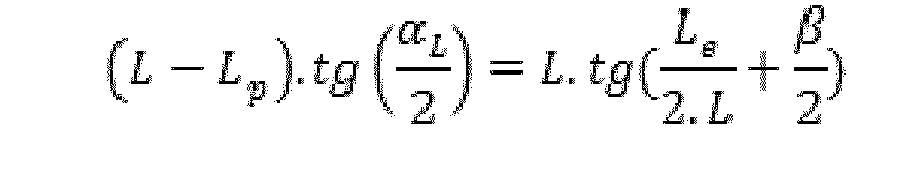
Structurellement, le dispositif 1 de l'invention comporte une structure rigide qui forme un conduit 6 destiné à être traversé par les rayons du faisceau laser 5 mis en forme. Ce conduit 6 comporte ainsi à chacune de ses extrémités un orifice, l'un d'entrée 2, l'autre de sortie 3.Structurally, the
Selon un mode de réalisation préféré mais non limitatif de l'invention, cette structure 6 rigide du dispositif est sensiblement rectiligne selon un axe moyen. Cet axe moyen peut être un axe perpendiculaire à une section du dispositif 1, centré au niveau de la section du dispositif 1, ou encore passant par un axe ou un point de symétrie d'une section du dispositif 1.According to a preferred but non-limiting embodiment of the invention, this
Selon une première alternative de réalisation, la paroi interne 4 de la structure 6 rigide est rendue réfléchissante avec un aspect de type poli miroir par un ou plusieurs traitements de surface ou par usinage. Un état de surface trop rugueux serait à l'origine de pertes énergétiques et diminuerait le rendement global du dispositif 1.According to a first alternative embodiment, the
Selon une seconde alternative de réalisation, la paroi interne 4 de la structure 6 rigide est rendu réfléchissante par positionnement d'au moins une lame 4 sur la face interne de la structure rigide. Cette lame forme alors un chemisage de la face interne 4 de la structure rigide 6. Cette solution alternative permet d'éviter un usinage à l'intérieure d'une structure fermée qui est une solution coûteuse.According to a second alternative embodiment, the
Selon une particularité de réalisation non limitative de l'invention, la paroi interne 4 du dispositif 1 de mise en forme de l'invention peut comporter une ou plusieurs facettes. Ce nombre de facettes peut dépendre de la forme d'au moins un des orifices du conduit 6 et notamment de la forme de l'orifice 3 de sortie du dispositif. Ce nombre de facettes permet ainsi d'imposer une forme géométrique particulière au faisceau laser 5 en sortie du dispositif 1. Ainsi, le dispositif 1 peut présenter une section de forme circulaire, ovoïde ou elliptique avec une facette unique à l'ensemble de la paroi interne 4 du dispositif 1. De même, le dispositif 1, lorsqu'il comporte plusieurs facettes, peut présenter une section de forme polygonale, par exemple rectangulaire ou carrée.According to a feature of non-limiting embodiment of the invention, the
Selon un mode de réalisation particulier du dispositif 1 qui n'est pas limitatif de l'invention, ce dispositif 1 présente un orifice 3 de sortie formé par une section agencée dans un plan disposé en biais par rapport à l'axe moyen du conduit du dispositif. Un exemple de réalisation est représenté sur la
Par ailleurs, le nombre de facettes entre l'orifice 2 d'entrée et l'orifice 3 de sortie du dispositif 1 de mise en forme peut varier. De même, la forme de ces parois 4 ou facettes réfléchissantes peut être de différents types : plane, concave, convexe ou de toutes formes souhaitées.Moreover, the number of facets between the
Selon une particularité de réalisation non limitative de l'invention, le dispositif 1 intègre des moyens de cloisonnement des orifices. Ces moyens de cloisonnement forment ainsi des hublots positionnés en entrée 2 et en sortie 3 du dispositif pour maintenir, à l'intérieur du conduit du dispositif 1, un milieu spécifique ou bien encore pour éviter toute pollution extérieure de l'intérieur du conduit. Ce milieu spécifique peut être formé par un liquide ou un gaz particulier, voire un solide particulier.According to a non-limiting embodiment of the invention, the
Par ailleurs, au niveau de l'orifice 3 de sortie du dispositif 1, l'ensemble de mise en forme de l'invention peut intégrer une optique permettant de compléter la mise en forme du faisceau laser 5 en redimensionnant la taille de ce faisceau 5.Furthermore, at the
L'ensemble de mise en forme peut également être associé à un dispositif de refroidissement par air ou par eau. Ce dispositif étant associé à l'ensemble de mise en forme en fonction de la puissance du faisceau laser traité par le dispositif 1 de mise en forme de l'invention.The shaping assembly can also be associated with an air or water cooling device. This device being associated with the shaping assembly according to the power of the laser beam processed by the
L'ensemble de mise en forme peut également associer un moyen générateur d'une lame d'air au niveau d'au moins un des orifices du dispositif 1, notamment de l'orifice 3 de sortie, pour limiter une éventuelle pollution des constituants du dispositif 1 de mise en forme.The shaping assembly can also associate a means generating an air gap at at least one of the orifices of the
Les différents éléments qui composent ou sont associés, voire intégrés à l'ensemble de mise en forme sont maintenus en positions les uns par rapport aux autres grâce à une structure de support adaptée.The various elements that make up or are associated, or even integrated into the shaping assembly are maintained in positions relative to each other through a suitable support structure.
Selon une particularité de réalisation, le dispositif 1 intégré à l'ensemble de mise en forme de rayons lumineux est utilisé dans un système particulier de l'invention. Ce système fait intervenir au moins deux ensembles de mise en forme positionnés côte à côte, chacun traitant un signal lumineux respectif formé par un faisceau indépendant. Les différents ensembles de ce système peuvent être disposés selon le cas en colonne, en ligne, en diagonale et/ou selon toutes combinaisons lignes/colonnes/diagonales. Ce système permet ainsi de créer un faisceau combiné étendu au niveau duquel les densités d'énergie peuvent être modulées localement par action sur la puissance des faisceaux incidents respectifs.According to a particular embodiment, the
Il est bien entendu que le dispositif de mise en forme de l'invention est adapté pour fonctionner pour une large gamme de longueurs d'ondes, comprise notamment entre l'ultra-violet et l'infrarouge.It is understood that the shaping device of the invention is adapted to operate for a wide range of wavelengths, including between ultraviolet and infrared.
Bien entendu, l'invention n'est pas limitée au mode de réalisation décrit et représenté aux dessins annexés. Des modifications restent possibles, notamment du point de vue de la constitution des divers éléments ou par substitution d'équivalents techniques, sans sortir pour autant du domaine de protection de l'invention.Of course, the invention is not limited to the embodiment described and shown in the accompanying drawings. Modifications are possible, particularly from the point of view of the constitution of the various elements or by substitution of technical equivalents, without departing from the scope of protection of the invention.
Claims (12)
Applications Claiming Priority (1)
| Application Number | Priority Date | Filing Date | Title |
|---|---|---|---|
| FR1250286A FR2985579B1 (en) | 2012-01-11 | 2012-01-11 | DEVICE FOR FORMING THE LUMINOUS RADIUS OF A LASER BEAM |
Publications (2)
| Publication Number | Publication Date |
|---|---|
| EP2615486A1 true EP2615486A1 (en) | 2013-07-17 |
| EP2615486B1 EP2615486B1 (en) | 2022-03-02 |
Family
ID=47605433
Family Applications (1)
| Application Number | Title | Priority Date | Filing Date |
|---|---|---|---|
| EP13305024.5A Active EP2615486B1 (en) | 2012-01-11 | 2013-01-11 | Laser beam shaping apparatus |
Country Status (4)
| Country | Link |
|---|---|
| US (1) | US8824052B2 (en) |
| EP (1) | EP2615486B1 (en) |
| ES (1) | ES2913129T3 (en) |
| FR (1) | FR2985579B1 (en) |
Cited By (2)
| Publication number | Priority date | Publication date | Assignee | Title |
|---|---|---|---|---|
| CN103513426A (en) * | 2013-10-11 | 2014-01-15 | 江苏大学 | Method of improving laser processing efficiency by optimizing light beam quality |
| EP3096419A1 (en) * | 2015-05-08 | 2016-11-23 | Novanta Corporation | Waveguide beam conditioning for a high powered laser |
Families Citing this family (5)
| Publication number | Priority date | Publication date | Assignee | Title |
|---|---|---|---|---|
| US9231363B1 (en) * | 2015-02-12 | 2016-01-05 | Coherent, Inc. | Optical pumping apparatus for slab lasers and amplifiers |
| US11114813B2 (en) * | 2015-11-25 | 2021-09-07 | Raytheon Company | Integrated pumplight homogenizer and signal injector for high-power laser system |
| US10297968B2 (en) | 2015-11-25 | 2019-05-21 | Raytheon Company | High-gain single planar waveguide (PWG) amplifier laser system |
| DE102018104629A1 (en) * | 2018-02-28 | 2019-08-29 | Branson Ultraschall Niederlassung Der Emerson Technologies Gmbh & Co. Ohg | Waveguide for plastic welding, assembly for plastic welding, a welding method and a method of manufacturing a waveguide |
| CN113459678B (en) * | 2021-07-28 | 2022-06-07 | 杭州爱新凯科技有限公司 | Laser 3D printer edge light spot area compensation method |
Citations (3)
| Publication number | Priority date | Publication date | Assignee | Title |
|---|---|---|---|---|
| US6554464B1 (en) * | 2000-02-16 | 2003-04-29 | Ultratech Stepper, Inc. | Apparatus for and method of reducing or eliminating interference effects in a light tunnel illuminator |
| US20050079645A1 (en) * | 2003-09-30 | 2005-04-14 | Tomoaki Moriwaka | Beam homogenizer, laser irradiation apparatus, and method for manufacturing semiconductor device |
| JP2006251459A (en) * | 2005-03-11 | 2006-09-21 | Olympus Corp | Optical device, image modulating device, and projector |
-
2012
- 2012-01-11 FR FR1250286A patent/FR2985579B1/en active Active
-
2013
- 2013-01-11 ES ES13305024T patent/ES2913129T3/en active Active
- 2013-01-11 EP EP13305024.5A patent/EP2615486B1/en active Active
- 2013-01-11 US US13/739,295 patent/US8824052B2/en active Active
Patent Citations (3)
| Publication number | Priority date | Publication date | Assignee | Title |
|---|---|---|---|---|
| US6554464B1 (en) * | 2000-02-16 | 2003-04-29 | Ultratech Stepper, Inc. | Apparatus for and method of reducing or eliminating interference effects in a light tunnel illuminator |
| US20050079645A1 (en) * | 2003-09-30 | 2005-04-14 | Tomoaki Moriwaka | Beam homogenizer, laser irradiation apparatus, and method for manufacturing semiconductor device |
| JP2006251459A (en) * | 2005-03-11 | 2006-09-21 | Olympus Corp | Optical device, image modulating device, and projector |
Cited By (2)
| Publication number | Priority date | Publication date | Assignee | Title |
|---|---|---|---|---|
| CN103513426A (en) * | 2013-10-11 | 2014-01-15 | 江苏大学 | Method of improving laser processing efficiency by optimizing light beam quality |
| EP3096419A1 (en) * | 2015-05-08 | 2016-11-23 | Novanta Corporation | Waveguide beam conditioning for a high powered laser |
Also Published As
| Publication number | Publication date |
|---|---|
| ES2913129T3 (en) | 2022-05-31 |
| FR2985579A1 (en) | 2013-07-12 |
| EP2615486B1 (en) | 2022-03-02 |
| US20130194673A1 (en) | 2013-08-01 |
| FR2985579B1 (en) | 2016-10-14 |
| US8824052B2 (en) | 2014-09-02 |
Similar Documents
| Publication | Publication Date | Title |
|---|---|---|
| EP2615486B1 (en) | Laser beam shaping apparatus | |
| EP2334465B1 (en) | Laser cutting method and equipment, with means for modifying the laser beam quality factor by a diffractive optical component | |
| KR101696055B1 (en) | Multiple beam combiner for laser processing apparatus and a radiation source | |
| EP2518545A1 (en) | Device for transmitting light energy and transmission method therefor | |
| US10359687B2 (en) | Method to generate terahertz radiation and terahertz radiation source | |
| EP3060957A1 (en) | Modular laser apparatus | |
| FR2977513A1 (en) | Cutting a workpiece e.g. stainless steel by laser beam, comprises generating laser beam having Gaussian-type intensity distribution using laser source, and modifying laser beam so as to obtain ring type intensity distribution laser beam | |
| JP2014044365A (en) | Pulse front inclined optical system and terahertz wave generator | |
| CN113059807B (en) | High axial resolution three-dimensional printing method and device based on uniform active light sheet | |
| WO2021152245A1 (en) | Device for processing a light beam via a multi-plane converter with a view to forming it into a predetermined shape | |
| FR2652421A1 (en) | OPTICAL COMPRESSOR OF PULSES. | |
| EP0180509B1 (en) | Method and apparatus for a controllable and stable phase modulation | |
| FR2961731A1 (en) | Cutting a piece by laser beam, comprises generating a laser beam producing a Gaussian type current distribution using fiber laser source or disk, modifying the beam generated by the laser source, and cutting the piece using the laser beam | |
| EP1212814B1 (en) | Pumped laser and optimised lasing medium | |
| WO2024002600A1 (en) | Optical device for scanning a light beam over a part to be machined | |
| FR3017495A1 (en) | HIGH-ENERGY FEMTOSECOND LASER SYSTEM AND REDUCED DURATION PULSE | |
| CN116931286B (en) | Beam shaping module, method and device | |
| US20220382041A1 (en) | Reflective spiral phase plate, and apparatus for generating laguerre gaussian beam comprising same | |
| FR3076655A1 (en) | OPTICAL DEVICE FOR X-RAY | |
| WO2024074241A1 (en) | Optical substrate having integrated antennas, and spectrometer comprising same | |
| Holdsworth et al. | Off-axis parabolic optical relays: almost perfect imaging | |
| FR2844060A3 (en) | Optical device using an optical fluid, uses optical fluid pumped tangentially into container in shape of a logarithmic spiral and extracted axially to filter infra-red and ultraviolet light | |
| WO2011070306A1 (en) | Method and device for converting a laser beam with gaussian power distribution into a laser beam with uniform power distribution | |
| EP1317033A2 (en) | Laser beam amplification through pumping of a non-linear medium and laser device comprising such an amplifier | |
| FR2995386A3 (en) | Lighting apparatus for e.g. lighting living room, has light source providing light flux that undergo total internal reflection from lateral sides, where light is output after total internal reflection through one of convergent lateral sides |
Legal Events
| Date | Code | Title | Description |
|---|---|---|---|
| PUAI | Public reference made under article 153(3) epc to a published international application that has entered the european phase |
Free format text: ORIGINAL CODE: 0009012 |
|
| AK | Designated contracting states |
Kind code of ref document: A1 Designated state(s): AL AT BE BG CH CY CZ DE DK EE ES FI FR GB GR HR HU IE IS IT LI LT LU LV MC MK MT NL NO PL PT RO RS SE SI SK SM TR |
|
| AX | Request for extension of the european patent |
Extension state: BA ME |
|
| 17P | Request for examination filed |
Effective date: 20131230 |
|
| RBV | Designated contracting states (corrected) |
Designated state(s): AL AT BE BG CH CY CZ DE DK EE ES FI FR GB GR HR HU IE IS IT LI LT LU LV MC MK MT NL NO PL PT RO RS SE SI SK SM TR |
|
| STAA | Information on the status of an ep patent application or granted ep patent |
Free format text: STATUS: EXAMINATION IS IN PROGRESS |
|
| 17Q | First examination report despatched |
Effective date: 20161129 |
|
| STAA | Information on the status of an ep patent application or granted ep patent |
Free format text: STATUS: EXAMINATION IS IN PROGRESS |
|
| GRAP | Despatch of communication of intention to grant a patent |
Free format text: ORIGINAL CODE: EPIDOSNIGR1 |
|
| STAA | Information on the status of an ep patent application or granted ep patent |
Free format text: STATUS: GRANT OF PATENT IS INTENDED |
|
| INTG | Intention to grant announced |
Effective date: 20210923 |
|
| GRAS | Grant fee paid |
Free format text: ORIGINAL CODE: EPIDOSNIGR3 |
|
| GRAA | (expected) grant |
Free format text: ORIGINAL CODE: 0009210 |
|
| STAA | Information on the status of an ep patent application or granted ep patent |
Free format text: STATUS: THE PATENT HAS BEEN GRANTED |
|
| AK | Designated contracting states |
Kind code of ref document: B1 Designated state(s): AL AT BE BG CH CY CZ DE DK EE ES FI FR GB GR HR HU IE IS IT LI LT LU LV MC MK MT NL NO PL PT RO RS SE SI SK SM TR |
|
| REG | Reference to a national code |
Ref country code: GB Ref legal event code: FG4D Free format text: NOT ENGLISH |
|
| REG | Reference to a national code |
Ref country code: CH Ref legal event code: EP Ref country code: AT Ref legal event code: REF Ref document number: 1472737 Country of ref document: AT Kind code of ref document: T Effective date: 20220315 |
|
| REG | Reference to a national code |
Ref country code: DE Ref legal event code: R096 Ref document number: 602013081016 Country of ref document: DE |
|
| REG | Reference to a national code |
Ref country code: IE Ref legal event code: FG4D Free format text: LANGUAGE OF EP DOCUMENT: FRENCH |
|
| REG | Reference to a national code |
Ref country code: NL Ref legal event code: FP |
|
| REG | Reference to a national code |
Ref country code: ES Ref legal event code: FG2A Ref document number: 2913129 Country of ref document: ES Kind code of ref document: T3 Effective date: 20220531 |
|
| REG | Reference to a national code |
Ref country code: LT Ref legal event code: MG9D |
|
| PG25 | Lapsed in a contracting state [announced via postgrant information from national office to epo] |
Ref country code: SE Free format text: LAPSE BECAUSE OF FAILURE TO SUBMIT A TRANSLATION OF THE DESCRIPTION OR TO PAY THE FEE WITHIN THE PRESCRIBED TIME-LIMIT Effective date: 20220302 Ref country code: RS Free format text: LAPSE BECAUSE OF FAILURE TO SUBMIT A TRANSLATION OF THE DESCRIPTION OR TO PAY THE FEE WITHIN THE PRESCRIBED TIME-LIMIT Effective date: 20220302 Ref country code: NO Free format text: LAPSE BECAUSE OF FAILURE TO SUBMIT A TRANSLATION OF THE DESCRIPTION OR TO PAY THE FEE WITHIN THE PRESCRIBED TIME-LIMIT Effective date: 20220602 Ref country code: LT Free format text: LAPSE BECAUSE OF FAILURE TO SUBMIT A TRANSLATION OF THE DESCRIPTION OR TO PAY THE FEE WITHIN THE PRESCRIBED TIME-LIMIT Effective date: 20220302 Ref country code: HR Free format text: LAPSE BECAUSE OF FAILURE TO SUBMIT A TRANSLATION OF THE DESCRIPTION OR TO PAY THE FEE WITHIN THE PRESCRIBED TIME-LIMIT Effective date: 20220302 Ref country code: BG Free format text: LAPSE BECAUSE OF FAILURE TO SUBMIT A TRANSLATION OF THE DESCRIPTION OR TO PAY THE FEE WITHIN THE PRESCRIBED TIME-LIMIT Effective date: 20220602 |
|
| REG | Reference to a national code |
Ref country code: AT Ref legal event code: MK05 Ref document number: 1472737 Country of ref document: AT Kind code of ref document: T Effective date: 20220302 |
|
| PG25 | Lapsed in a contracting state [announced via postgrant information from national office to epo] |
Ref country code: PL Free format text: LAPSE BECAUSE OF FAILURE TO SUBMIT A TRANSLATION OF THE DESCRIPTION OR TO PAY THE FEE WITHIN THE PRESCRIBED TIME-LIMIT Effective date: 20220302 Ref country code: LV Free format text: LAPSE BECAUSE OF FAILURE TO SUBMIT A TRANSLATION OF THE DESCRIPTION OR TO PAY THE FEE WITHIN THE PRESCRIBED TIME-LIMIT Effective date: 20220302 Ref country code: GR Free format text: LAPSE BECAUSE OF FAILURE TO SUBMIT A TRANSLATION OF THE DESCRIPTION OR TO PAY THE FEE WITHIN THE PRESCRIBED TIME-LIMIT Effective date: 20220603 Ref country code: FI Free format text: LAPSE BECAUSE OF FAILURE TO SUBMIT A TRANSLATION OF THE DESCRIPTION OR TO PAY THE FEE WITHIN THE PRESCRIBED TIME-LIMIT Effective date: 20220302 |
|
| PG25 | Lapsed in a contracting state [announced via postgrant information from national office to epo] |
Ref country code: SM Free format text: LAPSE BECAUSE OF FAILURE TO SUBMIT A TRANSLATION OF THE DESCRIPTION OR TO PAY THE FEE WITHIN THE PRESCRIBED TIME-LIMIT Effective date: 20220302 Ref country code: SK Free format text: LAPSE BECAUSE OF FAILURE TO SUBMIT A TRANSLATION OF THE DESCRIPTION OR TO PAY THE FEE WITHIN THE PRESCRIBED TIME-LIMIT Effective date: 20220302 Ref country code: RO Free format text: LAPSE BECAUSE OF FAILURE TO SUBMIT A TRANSLATION OF THE DESCRIPTION OR TO PAY THE FEE WITHIN THE PRESCRIBED TIME-LIMIT Effective date: 20220302 Ref country code: PT Free format text: LAPSE BECAUSE OF FAILURE TO SUBMIT A TRANSLATION OF THE DESCRIPTION OR TO PAY THE FEE WITHIN THE PRESCRIBED TIME-LIMIT Effective date: 20220704 Ref country code: EE Free format text: LAPSE BECAUSE OF FAILURE TO SUBMIT A TRANSLATION OF THE DESCRIPTION OR TO PAY THE FEE WITHIN THE PRESCRIBED TIME-LIMIT Effective date: 20220302 Ref country code: CZ Free format text: LAPSE BECAUSE OF FAILURE TO SUBMIT A TRANSLATION OF THE DESCRIPTION OR TO PAY THE FEE WITHIN THE PRESCRIBED TIME-LIMIT Effective date: 20220302 Ref country code: AT Free format text: LAPSE BECAUSE OF FAILURE TO SUBMIT A TRANSLATION OF THE DESCRIPTION OR TO PAY THE FEE WITHIN THE PRESCRIBED TIME-LIMIT Effective date: 20220302 |
|
| PG25 | Lapsed in a contracting state [announced via postgrant information from national office to epo] |
Ref country code: IS Free format text: LAPSE BECAUSE OF FAILURE TO SUBMIT A TRANSLATION OF THE DESCRIPTION OR TO PAY THE FEE WITHIN THE PRESCRIBED TIME-LIMIT Effective date: 20220702 Ref country code: AL Free format text: LAPSE BECAUSE OF FAILURE TO SUBMIT A TRANSLATION OF THE DESCRIPTION OR TO PAY THE FEE WITHIN THE PRESCRIBED TIME-LIMIT Effective date: 20220302 |
|
| REG | Reference to a national code |
Ref country code: DE Ref legal event code: R097 Ref document number: 602013081016 Country of ref document: DE |
|
| RAP4 | Party data changed (patent owner data changed or rights of a patent transferred) |
Owner name: INDUSTRIALISATION DES RECHERCHES SUR LES PROCEDES ET LES APPLICATIONS DU LASER (SOCIETE COOPERATIVE D'INTERET COLLECTIF) |
|
| PLBE | No opposition filed within time limit |
Free format text: ORIGINAL CODE: 0009261 |
|
| STAA | Information on the status of an ep patent application or granted ep patent |
Free format text: STATUS: NO OPPOSITION FILED WITHIN TIME LIMIT |
|
| PG25 | Lapsed in a contracting state [announced via postgrant information from national office to epo] |
Ref country code: DK Free format text: LAPSE BECAUSE OF FAILURE TO SUBMIT A TRANSLATION OF THE DESCRIPTION OR TO PAY THE FEE WITHIN THE PRESCRIBED TIME-LIMIT Effective date: 20220302 |
|
| 26N | No opposition filed |
Effective date: 20221205 |
|
| PG25 | Lapsed in a contracting state [announced via postgrant information from national office to epo] |
Ref country code: SI Free format text: LAPSE BECAUSE OF FAILURE TO SUBMIT A TRANSLATION OF THE DESCRIPTION OR TO PAY THE FEE WITHIN THE PRESCRIBED TIME-LIMIT Effective date: 20220302 |
|
| PGFP | Annual fee paid to national office [announced via postgrant information from national office to epo] |
Ref country code: FR Payment date: 20230124 Year of fee payment: 11 Ref country code: ES Payment date: 20230330 Year of fee payment: 11 Ref country code: CH Payment date: 20230111 Year of fee payment: 11 |
|
| REG | Reference to a national code |
Ref country code: DE Ref legal event code: R081 Ref document number: 602013081016 Country of ref document: DE Owner name: INDUSTRIALISATION DES RECHERCHES SUR LES PROCE, FR Free format text: FORMER OWNER: IREPA LASER, ILLKIRCH-GRAFFENSTADEN, FR |
|
| REG | Reference to a national code |
Ref country code: BE Ref legal event code: HC Owner name: INDUSTRIALISATION DES RECHERCHES SUR LES PROCEDES ET LES APPLICATIONS DU LASER; FR Free format text: DETAILS ASSIGNMENT: CHANGE OF OWNER(S), CHANGE OF OWNER(S) NAME; FORMER OWNER NAME: IREPA LASER Effective date: 20230316 |
|
| PGFP | Annual fee paid to national office [announced via postgrant information from national office to epo] |
Ref country code: TR Payment date: 20230109 Year of fee payment: 11 Ref country code: IT Payment date: 20230120 Year of fee payment: 11 Ref country code: GB Payment date: 20230119 Year of fee payment: 11 Ref country code: DE Payment date: 20230123 Year of fee payment: 11 Ref country code: BE Payment date: 20230119 Year of fee payment: 11 |
|
| REG | Reference to a national code |
Ref country code: NL Ref legal event code: PD Owner name: INDUSTRIALISATION DES RECHERCHES SUR LES PROCEDES ET LES APPLICATIONS DU LASER (SOCIETE COOPERATIVE D'INTERET COLLECTIF); FR Free format text: DETAILS ASSIGNMENT: CHANGE OF OWNER(S), CHANGE OF LEGAL ENTITY; FORMER OWNER NAME: IREPA LASER Effective date: 20230614 |
|
| PGFP | Annual fee paid to national office [announced via postgrant information from national office to epo] |
Ref country code: NL Payment date: 20230119 Year of fee payment: 11 |
|
| PG25 | Lapsed in a contracting state [announced via postgrant information from national office to epo] |
Ref country code: LU Free format text: LAPSE BECAUSE OF NON-PAYMENT OF DUE FEES Effective date: 20230111 |
|
| PG25 | Lapsed in a contracting state [announced via postgrant information from national office to epo] |
Ref country code: IE Free format text: LAPSE BECAUSE OF NON-PAYMENT OF DUE FEES Effective date: 20230111 |