EP2615429A1 - Thermal type fluid flow rate measuring device - Google Patents
Thermal type fluid flow rate measuring device Download PDFInfo
- Publication number
- EP2615429A1 EP2615429A1 EP11823380.8A EP11823380A EP2615429A1 EP 2615429 A1 EP2615429 A1 EP 2615429A1 EP 11823380 A EP11823380 A EP 11823380A EP 2615429 A1 EP2615429 A1 EP 2615429A1
- Authority
- EP
- European Patent Office
- Prior art keywords
- flow rate
- detection element
- intake air
- air temperature
- measurement device
- Prior art date
- Legal status (The legal status is an assumption and is not a legal conclusion. Google has not performed a legal analysis and makes no representation as to the accuracy of the status listed.)
- Withdrawn
Links
Images


Classifications
-
- G—PHYSICS
- G01—MEASURING; TESTING
- G01F—MEASURING VOLUME, VOLUME FLOW, MASS FLOW OR LIQUID LEVEL; METERING BY VOLUME
- G01F1/00—Measuring the volume flow or mass flow of fluid or fluent solid material wherein the fluid passes through a meter in a continuous flow
- G01F1/68—Measuring the volume flow or mass flow of fluid or fluent solid material wherein the fluid passes through a meter in a continuous flow by using thermal effects
- G01F1/684—Structural arrangements; Mounting of elements, e.g. in relation to fluid flow
- G01F1/6845—Micromachined devices
-
- G—PHYSICS
- G01—MEASURING; TESTING
- G01F—MEASURING VOLUME, VOLUME FLOW, MASS FLOW OR LIQUID LEVEL; METERING BY VOLUME
- G01F15/00—Details of, or accessories for, apparatus of groups G01F1/00 - G01F13/00 insofar as such details or appliances are not adapted to particular types of such apparatus
- G01F15/18—Supports or connecting means for meters
- G01F15/185—Connecting means, e.g. bypass conduits
Definitions
- the present invention relates to a thermal fluid flow rate measurement device, and more particularly to a thermal fluid flow rate measurement device suitable for measuring intake air of an internal combustion engine.
- a thermal fluid flow rate measurement device is disposed in an electronically controlled fuel injection device of an internal combustion engine for automobiles and the like and used to measure an intake air amount.
- the thermal fluid flow rate measurement device mostly includes an auxiliary passage in which a part of fluid flows.
- An intake air temperature detection element and a flow rate detection element, such as a temperature-sensitive resistor, are disposed in the auxiliary passage.
- an intake air temperature detection element is disposed in the auxiliary passage to measure the temperature of ambient air as described in Japanese Unexamined Patent Application Publication No. 2006-234766 .
- Patent Literature 1 Japanese Unexamined Patent Application Publication No. 2006-234766
- the intake air temperature detection element for a conventional thermal fluid flow rate measurement device is disposed in the auxiliary passage.
- an intake temperature in the auxiliary passage can be accurately measured.
- air comes into contact with the intake air temperature detection element and disturbs the flow of air in the auxiliary passage. This makes it impossible to accurately measure the intake air amount.
- the intake air temperature detection element is easily affected by ambient heat, such as the heat radiated from a heated intake pipe or from a heated circuit in the device.
- ambient heat such as the heat radiated from a heated intake pipe or from a heated circuit in the device.
- an assembly worker may inadvertently come into contact with the intake air temperature detection element to adversely affect its accuracy.
- the effective cross-sectional area in the intake pipe that is occupied by the intake air temperature detection element may increase depending on its mounting position. Therefore, the position in which the intake air temperature detection element can be mounted without increasing the loss of pressure is limited.
- the present invention has been made in view of the above circumstances and has an object to provide a thermal fluid flow rate measurement device capable of avoiding a disordered air flow in the auxiliary passage due to the mounting of the intake air temperature detection element and measuring the intake air temperature with high accuracy.
- a thermal fluid flow rate measurement device including an auxiliary passage, a base member, a flow rate detection element, and a circuit section.
- the auxiliary passage is inserted into a main passage to acquire a part of an air flow in the main passage.
- the base member forms a part of the auxiliary passage.
- the flow rate detection element is supported by the base member and disposed in the auxiliary passage to detect the flow rate of a fluid.
- the circuit section is electrically connected to the flow rate detection element and housed in a circuit chamber formed by a mold member that is a part of the auxiliary passage.
- An intake air temperature detection element is disposed outside the auxiliary passage and mounted on an upstream end face of the mold member relative to the air flow to detect an intake air temperature.
- the present invention inhibits a fluid flow rate measurement device and peripheral parts from thermally affecting an intake air temperature detection element and measures an intake air temperature with high accuracy.
- the present invention also prevents the flow of air in an auxiliary passage from being disordered when the intake air temperature detection element is installed.
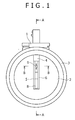
- Fig. 1 is a diagram illustrating how a thermal fluid flow rate measurement device 1 is mounted on a body 3.
- the thermal fluid flow rate measurement device 1 is inserted into the body 3, which forms a main passage 2.
- the thermal fluid flow rate measurement device 1 includes a mold member 4, a base member 5, and a cover member 6. These members form an auxiliary passage 8 that takes in a part of an air flow 7 in the main passage 2.
- Fig. 2 is a cross-sectional view taken along the line A-A of Fig. 1 .
- Fig. 3 is a cross-sectional view taken along the line B-B of Fig. 1 .
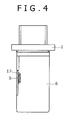
- Fig. 4 shows the thermal fluid flow rate measurement device 1.
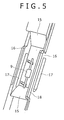
- Fig. 5 is an enlarged view of a dent 13 in which an intake air temperature detection element 9 is mounted.
- the circuit section 10 is housed in a circuit chamber 21, which is a space formed by the mold member 4.
- the flow rate detection element 11 is disposed in the auxiliary passage 8.
- the flow rate detection element 11 is electrically connected to the circuit section 10, for instance, by wire bonding.
- the auxiliary passage 8 takes in a part of the air flow 7 in the main passage 2 from an inlet that is open upstream of the air flow 7. As shown in Fig. 2 , a fluid flowing inward from the inlet changes its flow direction by 180 degrees before it reaches the flow rate detection element 11. As such a configuration is employed, dust, contaminants, water, and other substances included in the fluid collide against a wall of the auxiliary passage 8 and lose their kinetic energy. This significantly reduces the possibility of such substances directly colliding against the flow rate detection element 11. As a result, the reliability of the thermal fluid flow rate measurement device 1 increases.
- variable valve timing is recently employed for an engine
- the air flow 7 in the main passage 2 is not always stable but is pulsating. In some cases, a back-flow occurs so that air flow from the engine.
- the use of the auxiliary passage 8 is effective for accurate flow rate detection. More specifically, the flow rate can be accurately detected by forming an outlet (not shown) for the back-flow side and using the auxiliary passage 8 that should preferably be symmetrical in both upstream and downstream directions.
- the intake air temperature detection element 9 is disposed in a region facing the auxiliary passage 8, the air flow taken into the auxiliary passage 8 strikes against the intake air temperature detection element 9 and becomes disordered. This decreases the accuracy of air flow rate detection by the flow rate detection element 11.
- the thermal fluid flow rate measurement device 1 includes the dent 13 that is positioned near the circuit section 10 and the flow rate detection element 11, disposed on an upstream end face 12, and concaved in the downstream direction.
- the intake air temperature detection element 9 is disposed in a space that is vertically extended from the upstream end face 12 of the dent 13.
- the intake air temperature detection element 9 is disposed outside the auxiliary passage 8 although it was previously disposed in the auxiliary passage 8, the air flow, which becomes disordered as it strikes against the intake air temperature detection element 9, does not reach the flow rate detection element 11 disposed in the auxiliary passage 8. This makes it possible to accurately detect the air flow 7 in the main passage 2.
- the intake air temperature detection element 9 is disposed near the flow rate detection element 11, it is possible to measure an air temperature that is substantially equal to the temperature of air reaching the flow rate detection element 11. Therefore, accurate temperature correction can be made. Consequently, flow rate detection can be achieved with increased accuracy.
- the intake air temperature detection element 9 is disposed on the upstream end face 12, the heat radiated from the mold member 4, base member 5, cover member 6, and circuit section 10 of the thermal fluid flow rate measurement device 1 is conveyed downstream by the air flow 7. This makes it possible to avoid the thermal influence of the above members. Consequently, intake air temperature detection can be achieved with high accuracy.
- a terminal 14 connecting the circuit section 10 to the intake air temperature detection element 9 can be relatively shortened. This not only provides increased manufacturing accuracy but also achieves material cost reduction. As a result, the overall cost can be reduced.
- the dent 13 is formed by the mold member 4, the base member 5, and the cover member 6.
- the mold member 4 for the dent 13 has a slope (narrowed downstream of the air flow) 15. As the slope 15 increases the speed of air flowing in the dent 13, the intake air temperature detection element 9 is not easily affected by heat radiated from the surroundings.
- the base member 5 and cover member 6 for the dent 13 are each provided with a rib 16.
- Each rib 16 increases the rigidity of the thermal fluid flow rate measurement device 1.
- the dent 13 is surrounded by each rib 16 to prevent, for example, an assembly worker from inadvertently come into contact with the intake air temperature detection element 9.
- each rib 16 There is a through-hole 17 in each rib 16.
- the air reaching the dent 13 passes through the through-hole 17 and becomes discharged to the main passage 2. This facilitates the flow of air in the dent 13 so that the intake air temperature detection element 9 is not easily affected by heat radiated from the surroundings.
- each rib 16 for the base member 5 and for the cover member 6 has a chamfer 18 that is oriented from the center of the device to the outside of the device. This ensures that the air flowing outside of the rib 20 is higher in speed than the air flowing inside of the rib 19. Therefore, the air flowing outside of the rib 20 is lower in pressure than the air flowing inside of the rib 19. In other words, a pressure difference arises between the air flowing inside of the rib 19 and the air flowing outside of the rib 20. This pressure difference urges the air to become discharged from the inside of the rib 19 to the outside of the rib 20 through the through-hole 17. Consequently, the flow of air in the dent 13 is facilitated so that the intake air temperature detection element 9 is not easily affected by heat radiated from the surroundings.
- the present invention is applicable not only to the thermal fluid flow rate measurement device according to the above-described embodiment, but also to various other measurement devices such as a temperature measurement device, a humidity measurement device, and a gas measurement device.
Landscapes
- Physics & Mathematics (AREA)
- Fluid Mechanics (AREA)
- General Physics & Mathematics (AREA)
- Measuring Volume Flow (AREA)
Abstract
Description
- The present invention relates to a thermal fluid flow rate measurement device, and more particularly to a thermal fluid flow rate measurement device suitable for measuring intake air of an internal combustion engine.
- A thermal fluid flow rate measurement device is disposed in an electronically controlled fuel injection device of an internal combustion engine for automobiles and the like and used to measure an intake air amount. In recent years, the thermal fluid flow rate measurement device mostly includes an auxiliary passage in which a part of fluid flows. An intake air temperature detection element and a flow rate detection element, such as a temperature-sensitive resistor, are disposed in the auxiliary passage. In a previously developed thermal fluid flow rate measurement device, an intake air temperature detection element is disposed in the auxiliary passage to measure the temperature of ambient air as described in Japanese Unexamined Patent Application Publication No.
2006-234766 - Patent Literature 1: Japanese Unexamined Patent Application Publication No.
2006-234766 - As mentioned above, the intake air temperature detection element for a conventional thermal fluid flow rate measurement device is disposed in the auxiliary passage. When the intake air temperature detection element is disposed in the auxiliary passage, an intake temperature in the auxiliary passage can be accurately measured. However, air comes into contact with the intake air temperature detection element and disturbs the flow of air in the auxiliary passage. This makes it impossible to accurately measure the intake air amount.
- Further, if the intake air temperature detection element is disposed outside the auxiliary passage, the intake air temperature detection element is easily affected by ambient heat, such as the heat radiated from a heated intake pipe or from a heated circuit in the device. When the intake air temperature detection element is affected by such ambient heat, the intake air temperature cannot be accurately measured.
- Furthermore, an assembly worker, for example, may inadvertently come into contact with the intake air temperature detection element to adversely affect its accuracy.
- Moreover, the effective cross-sectional area in the intake pipe that is occupied by the intake air temperature detection element may increase depending on its mounting position. Therefore, the position in which the intake air temperature detection element can be mounted without increasing the loss of pressure is limited.
- The present invention has been made in view of the above circumstances and has an object to provide a thermal fluid flow rate measurement device capable of avoiding a disordered air flow in the auxiliary passage due to the mounting of the intake air temperature detection element and measuring the intake air temperature with high accuracy. Solution to Problem
- In accomplishing the above object, according to one aspect of the present invention, there is provided a thermal fluid flow rate measurement device including an auxiliary passage, a base member, a flow rate detection element, and a circuit section. The auxiliary passage is inserted into a main passage to acquire a part of an air flow in the main passage. The base member forms a part of the auxiliary passage. The flow rate detection element is supported by the base member and disposed in the auxiliary passage to detect the flow rate of a fluid. The circuit section is electrically connected to the flow rate detection element and housed in a circuit chamber formed by a mold member that is a part of the auxiliary passage. An intake air temperature detection element is disposed outside the auxiliary passage and mounted on an upstream end face of the mold member relative to the air flow to detect an intake air temperature. Advantageous Effects of Invention
- The present invention inhibits a fluid flow rate measurement device and peripheral parts from thermally affecting an intake air temperature detection element and measures an intake air temperature with high accuracy. The present invention also prevents the flow of air in an auxiliary passage from being disordered when the intake air temperature detection element is installed.
-
-
Fig. 1 is a front view illustrating an embodiment of a thermal fluid flow rate measurement device according to the present invention. -
Fig. 2 is a cross-sectional view taken along the line A-A ofFig. 1 . -
Fig. 3 is a cross-sectional view taken along the line B-B ofFig. 1 . -
Fig. 4 shows the thermal fluid flow rate measurement device. -
Fig. 5 is an enlarged view of a dent. - An embodiment of the present invention will now be described with reference to the accompanying drawings.
-
Fig. 1 is a diagram illustrating how a thermal fluid flowrate measurement device 1 is mounted on abody 3. - The thermal fluid flow
rate measurement device 1 is inserted into thebody 3, which forms amain passage 2. The thermal fluid flowrate measurement device 1 includes amold member 4, abase member 5, and acover member 6. These members form anauxiliary passage 8 that takes in a part of anair flow 7 in themain passage 2. -
Fig. 2 is a cross-sectional view taken along the line A-A ofFig. 1 .Fig. 3 is a cross-sectional view taken along the line B-B ofFig. 1 .Fig. 4 shows the thermal fluid flowrate measurement device 1.Fig. 5 is an enlarged view of adent 13 in which an intake airtemperature detection element 9 is mounted. - A
circuit section 10 and a flowrate detection element 11, which are supported by thebase member 5, are disposed in the thermal fluid flowrate measurement device 1. Thecircuit section 10 is housed in acircuit chamber 21, which is a space formed by themold member 4. The flowrate detection element 11 is disposed in theauxiliary passage 8. The flowrate detection element 11 is electrically connected to thecircuit section 10, for instance, by wire bonding. - The
auxiliary passage 8 takes in a part of theair flow 7 in themain passage 2 from an inlet that is open upstream of theair flow 7. As shown inFig. 2 , a fluid flowing inward from the inlet changes its flow direction by 180 degrees before it reaches the flowrate detection element 11. As such a configuration is employed, dust, contaminants, water, and other substances included in the fluid collide against a wall of theauxiliary passage 8 and lose their kinetic energy. This significantly reduces the possibility of such substances directly colliding against the flowrate detection element 11. As a result, the reliability of the thermal fluid flowrate measurement device 1 increases. - Further, as, for example, variable valve timing is recently employed for an engine, the
air flow 7 in themain passage 2 is not always stable but is pulsating. In some cases, a back-flow occurs so that air flow from the engine. - Under such circumstances, the use of the
auxiliary passage 8 is effective for accurate flow rate detection. More specifically, the flow rate can be accurately detected by forming an outlet (not shown) for the back-flow side and using theauxiliary passage 8 that should preferably be symmetrical in both upstream and downstream directions. - If, in the above instance, the intake air
temperature detection element 9 is disposed in a region facing theauxiliary passage 8, the air flow taken into theauxiliary passage 8 strikes against the intake airtemperature detection element 9 and becomes disordered. This decreases the accuracy of air flow rate detection by the flowrate detection element 11. - As such being the case, the thermal fluid flow
rate measurement device 1 includes thedent 13 that is positioned near thecircuit section 10 and the flowrate detection element 11, disposed on anupstream end face 12, and concaved in the downstream direction. The intake airtemperature detection element 9 is disposed in a space that is vertically extended from theupstream end face 12 of thedent 13. - Hence, as the intake air
temperature detection element 9 is disposed outside theauxiliary passage 8 although it was previously disposed in theauxiliary passage 8, the air flow, which becomes disordered as it strikes against the intake airtemperature detection element 9, does not reach the flowrate detection element 11 disposed in theauxiliary passage 8. This makes it possible to accurately detect theair flow 7 in themain passage 2. - Further, as the intake air
temperature detection element 9 is disposed near the flowrate detection element 11, it is possible to measure an air temperature that is substantially equal to the temperature of air reaching the flowrate detection element 11. Therefore, accurate temperature correction can be made. Consequently, flow rate detection can be achieved with increased accuracy. - Furthermore, as the intake air
temperature detection element 9 is disposed on theupstream end face 12, the heat radiated from themold member 4,base member 5,cover member 6, andcircuit section 10 of the thermal fluid flowrate measurement device 1 is conveyed downstream by theair flow 7. This makes it possible to avoid the thermal influence of the above members. Consequently, intake air temperature detection can be achieved with high accuracy. - Moreover, as the intake air
temperature detection element 9 is disposed near thecircuit section 10, a terminal 14 connecting thecircuit section 10 to the intake airtemperature detection element 9 can be relatively shortened. This not only provides increased manufacturing accuracy but also achieves material cost reduction. As a result, the overall cost can be reduced. - The
dent 13 is formed by themold member 4, thebase member 5, and thecover member 6. Themold member 4 for thedent 13 has a slope (narrowed downstream of the air flow) 15. As theslope 15 increases the speed of air flowing in thedent 13, the intake airtemperature detection element 9 is not easily affected by heat radiated from the surroundings. - The
base member 5 and covermember 6 for thedent 13 are each provided with arib 16. Eachrib 16 increases the rigidity of the thermal fluid flowrate measurement device 1. In addition, thedent 13 is surrounded by eachrib 16 to prevent, for example, an assembly worker from inadvertently come into contact with the intake airtemperature detection element 9. - There is a through-
hole 17 in eachrib 16. The air reaching thedent 13 passes through the through-hole 17 and becomes discharged to themain passage 2. This facilitates the flow of air in thedent 13 so that the intake airtemperature detection element 9 is not easily affected by heat radiated from the surroundings. - Further, the upstream portion of each
rib 16 for thebase member 5 and for thecover member 6 has achamfer 18 that is oriented from the center of the device to the outside of the device. This ensures that the air flowing outside of therib 20 is higher in speed than the air flowing inside of therib 19. Therefore, the air flowing outside of therib 20 is lower in pressure than the air flowing inside of therib 19. In other words, a pressure difference arises between the air flowing inside of therib 19 and the air flowing outside of therib 20. This pressure difference urges the air to become discharged from the inside of therib 19 to the outside of therib 20 through the through-hole 17. Consequently, the flow of air in thedent 13 is facilitated so that the intake airtemperature detection element 9 is not easily affected by heat radiated from the surroundings. - The present invention is applicable not only to the thermal fluid flow rate measurement device according to the above-described embodiment, but also to various other measurement devices such as a temperature measurement device, a humidity measurement device, and a gas measurement device.
-
List of Reference Signs 1 Thermal fluid flow rate measurement device 2 Main passage 3 Body 4 Mold member 5 Base member 6 Cover member 7 Air flow 8 Auxiliary passage 9 Intake air temperature detection element 10 Circuit section 11 Flow rate detection element 12 Upstream end face 13 Dent 14 Terminal 15 Slope 16 Rib 17 Through- hole 18 Chamfer 19 Inside of rib 20 Outside of rib 21 Circuit chamber
Claims (9)
- A thermal fluid flow rate measurement device comprising:an auxiliary passage that is inserted into a main passage to acquire a part of an air flow in the main passage;a base member that forms a part of the auxiliary passage;a flow rate detection element that is supported by the base member and disposed in the auxiliary passage to detect the flow rate of a fluid; anda circuit section that is electrically connected to the flow rate detection element and housed in a circuit chamber formed by a mold member which is a part of the auxiliary passage;wherein an intake air temperature detection element is disposed outside the auxiliary passage and mounted on an upstream end face of the mold member relative to the air flow to detect an intake air temperature.
- The thermal fluid flow rate measurement device according to claim 1, wherein the intake air temperature detection element is disposed in a dent that is mounted on an upstream end face of the mold member relative to the air flow and concaved in the downstream direction of the air flow.
- The thermal fluid flow rate measurement device according to claim 1, wherein the intake air temperature detection element is disposed near the circuit section.
- The thermal fluid flow rate measurement device according to claim 1, wherein the intake air temperature detection element is disposed near the flow rate detection element.
- The thermal fluid flow rate measurement device according to claim 2, wherein the dent is narrowed downstream of the air flow.
- The thermal fluid flow rate measurement device according to claim 2, wherein the intake air temperature detection element disposed in the dent is surrounded by the base member and by a cover member forming a part of the auxiliary passage.
- The thermal fluid flow rate measurement device according to claim 6, wherein at least one through-hole is provided in a portion of the base member and of the cover member that surrounds the intake air temperature detection element.
- The thermal fluid flow rate measurement device according to claim 7, wherein at least one chamfer is provided on a portion of the base member and of the cover member that surrounds the intake air temperature detection element.
- The thermal fluid flow rate measurement device according to claim 8, wherein the chamfer is provided so that the air flow moves outside of the base member and of the cover member.
Applications Claiming Priority (2)
| Application Number | Priority Date | Filing Date | Title |
|---|---|---|---|
| JP2010200451A JP2012058044A (en) | 2010-09-08 | 2010-09-08 | Thermal type fluid flow rate measuring device |
| PCT/JP2011/068544 WO2012032901A1 (en) | 2010-09-08 | 2011-08-16 | Thermal type fluid flow rate measuring device |
Publications (2)
| Publication Number | Publication Date |
|---|---|
| EP2615429A1 true EP2615429A1 (en) | 2013-07-17 |
| EP2615429A4 EP2615429A4 (en) | 2014-05-07 |
Family
ID=45810504
Family Applications (1)
| Application Number | Title | Priority Date | Filing Date |
|---|---|---|---|
| EP11823380.8A Withdrawn EP2615429A4 (en) | 2010-09-08 | 2011-08-16 | DEVICE FOR MEASURING THERMAL TYPE FLUID FLOW |
Country Status (5)
| Country | Link |
|---|---|
| US (1) | US20130152675A1 (en) |
| EP (1) | EP2615429A4 (en) |
| JP (1) | JP2012058044A (en) |
| CN (1) | CN103069256A (en) |
| WO (1) | WO2012032901A1 (en) |
Cited By (1)
| Publication number | Priority date | Publication date | Assignee | Title |
|---|---|---|---|---|
| US10260921B2 (en) | 2014-09-30 | 2019-04-16 | Hitachi Automotive Systems, Ltd. | Thermal flow meter |
Families Citing this family (7)
| Publication number | Priority date | Publication date | Assignee | Title |
|---|---|---|---|---|
| EP3064906A4 (en) * | 2013-10-31 | 2017-03-08 | Hitachi Automotive Systems, Ltd. | Airflow measurement device |
| DE102013226138A1 (en) * | 2013-12-17 | 2015-06-18 | Robert Bosch Gmbh | Pressure sensor device, air mass measuring device, air mass measuring system and pressure measuring method |
| JP6641789B2 (en) * | 2015-08-27 | 2020-02-05 | 株式会社デンソー | Air flow measurement device |
| JP6722989B2 (en) * | 2015-08-31 | 2020-07-15 | 日立オートモティブシステムズ株式会社 | Gas sensor device |
| CN107131907A (en) * | 2017-05-10 | 2017-09-05 | 苏州容启传感器科技有限公司 | Air mass flow detection device with environment monitoring function |
| DE102017112622A1 (en) * | 2017-06-08 | 2018-12-13 | Endress + Hauser Flowtec Ag | Thermal flowmeter |
| US11268920B2 (en) * | 2017-09-29 | 2022-03-08 | Hitachi Automotive Systems, Ltd. | Physical quantity detection device |
Family Cites Families (14)
| Publication number | Priority date | Publication date | Assignee | Title |
|---|---|---|---|---|
| JPH08219838A (en) * | 1995-02-15 | 1996-08-30 | Hitachi Ltd | Air flow measuring device |
| JP3475853B2 (en) * | 1998-12-21 | 2003-12-10 | 三菱電機株式会社 | Flow measurement device |
| JP3553422B2 (en) * | 1999-06-08 | 2004-08-11 | 三菱電機株式会社 | Flow sensor |
| JP4210122B2 (en) * | 2001-05-24 | 2009-01-14 | 株式会社日立製作所 | Heating resistor type flow measuring device |
| US6708561B2 (en) * | 2002-04-19 | 2004-03-23 | Visteon Global Technologies, Inc. | Fluid flow meter having an improved sampling channel |
| US7047805B2 (en) * | 2004-04-09 | 2006-05-23 | Visteon Global Technologies, Inc. | Fluid flow meter having an auxiliary flow passage |
| JP4020208B2 (en) * | 2004-11-30 | 2007-12-12 | 三菱電機株式会社 | Flow measuring device |
| JP4707412B2 (en) | 2005-02-28 | 2011-06-22 | 日立オートモティブシステムズ株式会社 | Gas flow measuring device |
| JP4979262B2 (en) * | 2006-05-08 | 2012-07-18 | 日立オートモティブシステムズ株式会社 | Flow measuring device |
| JP4416012B2 (en) * | 2007-06-06 | 2010-02-17 | 株式会社日立製作所 | Intake air flow rate measuring device |
| JP4426606B2 (en) * | 2007-06-29 | 2010-03-03 | 三菱電機株式会社 | Flow measuring device |
| JP5183164B2 (en) * | 2007-11-19 | 2013-04-17 | 日立オートモティブシステムズ株式会社 | Flow measuring device |
| JP5049996B2 (en) * | 2009-03-31 | 2012-10-17 | 日立オートモティブシステムズ株式会社 | Thermal flow meter |
| JP4929334B2 (en) * | 2009-09-30 | 2012-05-09 | 日立オートモティブシステムズ株式会社 | Flow measuring device |
-
2010
- 2010-09-08 JP JP2010200451A patent/JP2012058044A/en active Pending
-
2011
- 2011-08-16 CN CN2011800406096A patent/CN103069256A/en active Pending
- 2011-08-16 EP EP11823380.8A patent/EP2615429A4/en not_active Withdrawn
- 2011-08-16 WO PCT/JP2011/068544 patent/WO2012032901A1/en not_active Ceased
- 2011-08-16 US US13/817,925 patent/US20130152675A1/en not_active Abandoned
Cited By (1)
| Publication number | Priority date | Publication date | Assignee | Title |
|---|---|---|---|---|
| US10260921B2 (en) | 2014-09-30 | 2019-04-16 | Hitachi Automotive Systems, Ltd. | Thermal flow meter |
Also Published As
| Publication number | Publication date |
|---|---|
| CN103069256A (en) | 2013-04-24 |
| US20130152675A1 (en) | 2013-06-20 |
| WO2012032901A1 (en) | 2012-03-15 |
| JP2012058044A (en) | 2012-03-22 |
| EP2615429A4 (en) | 2014-05-07 |
Similar Documents
| Publication | Publication Date | Title |
|---|---|---|
| US20130152675A1 (en) | Thermal Fluid Flow Rate Measurement Device | |
| JP4412357B2 (en) | Air flow measurement device | |
| EP2060879A1 (en) | Air flow measuring instrument | |
| US20100242589A1 (en) | Thermal Type Flow Measuring Device | |
| CN106030258B (en) | Sensor assembly for determining at least one parameter of a fluid medium flowing through a channel | |
| JP2012058075A (en) | Thermal air meter | |
| US9927272B2 (en) | Air flow meter having a flow rate sensor and a physical quantity sensor | |
| US10260921B2 (en) | Thermal flow meter | |
| EP3217153B1 (en) | Thermal air flow meter | |
| US9410908B2 (en) | Humidity measurement device | |
| KR20130140256A (en) | Pressure sensor with temperature-sensing element and mounting structure of the same | |
| JP2008309621A (en) | Air flow measurement device | |
| JP4166705B2 (en) | Air flow measurement device | |
| US10739213B2 (en) | Temperature and humidity sensor | |
| US9829360B2 (en) | Air flow sensor including a resin-molded protection member for a temperature sensor | |
| US20200363249A1 (en) | Physical quantity measurement device | |
| JP6851466B2 (en) | Humidity measuring device | |
| US9689358B2 (en) | Air flow measuring device | |
| JP6207904B2 (en) | Temperature and humidity measuring device | |
| JP2006047272A (en) | Flow sensor | |
| EP3064906A1 (en) | Airflow measurement device | |
| JP2020003440A (en) | Thermal flow meter | |
| US20150020367A1 (en) | Air flow measuring device | |
| JPWO2018225351A1 (en) | Physical quantity detector |
Legal Events
| Date | Code | Title | Description |
|---|---|---|---|
| PUAI | Public reference made under article 153(3) epc to a published international application that has entered the european phase |
Free format text: ORIGINAL CODE: 0009012 |
|
| 17P | Request for examination filed |
Effective date: 20130408 |
|
| AK | Designated contracting states |
Kind code of ref document: A1 Designated state(s): AL AT BE BG CH CY CZ DE DK EE ES FI FR GB GR HR HU IE IS IT LI LT LU LV MC MK MT NL NO PL PT RO RS SE SI SK SM TR |
|
| DAX | Request for extension of the european patent (deleted) | ||
| A4 | Supplementary search report drawn up and despatched |
Effective date: 20140409 |
|
| RIC1 | Information provided on ipc code assigned before grant |
Ipc: G01F 15/18 20060101ALI20140403BHEP Ipc: G01F 1/68 20060101ALI20140403BHEP Ipc: G01F 1/684 20060101AFI20140403BHEP |
|
| STAA | Information on the status of an ep patent application or granted ep patent |
Free format text: STATUS: THE APPLICATION HAS BEEN WITHDRAWN |
|
| 18W | Application withdrawn |
Effective date: 20140731 |