EP2615366A1 - Lighting device with covering body - Google Patents
Lighting device with covering body Download PDFInfo
- Publication number
- EP2615366A1 EP2615366A1 EP12151186.9A EP12151186A EP2615366A1 EP 2615366 A1 EP2615366 A1 EP 2615366A1 EP 12151186 A EP12151186 A EP 12151186A EP 2615366 A1 EP2615366 A1 EP 2615366A1
- Authority
- EP
- European Patent Office
- Prior art keywords
- light
- covering body
- lighting device
- guiding member
- light source
- Prior art date
- Legal status (The legal status is an assumption and is not a legal conclusion. Google has not performed a legal analysis and makes no representation as to the accuracy of the status listed.)
- Withdrawn
Links
- 238000003860 storage Methods 0.000 claims abstract description 15
- 239000000463 material Substances 0.000 claims description 4
- 239000013307 optical fiber Substances 0.000 claims description 3
- 230000000694 effects Effects 0.000 abstract description 12
- 238000005034 decoration Methods 0.000 abstract description 11
- 238000000034 method Methods 0.000 description 8
- 230000005540 biological transmission Effects 0.000 description 3
- 230000004048 modification Effects 0.000 description 3
- 238000012986 modification Methods 0.000 description 3
- 230000002860 competitive effect Effects 0.000 description 2
- 238000010586 diagram Methods 0.000 description 2
- 238000009826 distribution Methods 0.000 description 2
- 238000004880 explosion Methods 0.000 description 2
- 238000004519 manufacturing process Methods 0.000 description 2
- 206010039203 Road traffic accident Diseases 0.000 description 1
- 239000011449 brick Substances 0.000 description 1
- 230000015556 catabolic process Effects 0.000 description 1
- 239000004568 cement Substances 0.000 description 1
- 239000004020 conductor Substances 0.000 description 1
- 230000007547 defect Effects 0.000 description 1
- 239000006185 dispersion Substances 0.000 description 1
- 239000000428 dust Substances 0.000 description 1
- 239000011521 glass Substances 0.000 description 1
- 230000017525 heat dissipation Effects 0.000 description 1
- 238000005286 illumination Methods 0.000 description 1
- 238000002955 isolation Methods 0.000 description 1
- 229920003023 plastic Polymers 0.000 description 1
- 239000002689 soil Substances 0.000 description 1
- XLYOFNOQVPJJNP-UHFFFAOYSA-N water Substances O XLYOFNOQVPJJNP-UHFFFAOYSA-N 0.000 description 1
Images






Classifications
-
- F—MECHANICAL ENGINEERING; LIGHTING; HEATING; WEAPONS; BLASTING
- F21—LIGHTING
- F21S—NON-PORTABLE LIGHTING DEVICES; SYSTEMS THEREOF; VEHICLE LIGHTING DEVICES SPECIALLY ADAPTED FOR VEHICLE EXTERIORS
- F21S10/00—Lighting devices or systems producing a varying lighting effect
- F21S10/005—Lighting devices or systems producing a varying lighting effect using light guides
-
- E—FIXED CONSTRUCTIONS
- E01—CONSTRUCTION OF ROADS, RAILWAYS, OR BRIDGES
- E01F—ADDITIONAL WORK, SUCH AS EQUIPPING ROADS OR THE CONSTRUCTION OF PLATFORMS, HELICOPTER LANDING STAGES, SIGNS, SNOW FENCES, OR THE LIKE
- E01F9/00—Arrangement of road signs or traffic signals; Arrangements for enforcing caution
- E01F9/50—Road surface markings; Kerbs or road edgings, specially adapted for alerting road users
- E01F9/535—Kerbs or road edgings specially adapted for alerting road users
- E01F9/547—Kerbs or road edgings specially adapted for alerting road users illuminated
-
- E—FIXED CONSTRUCTIONS
- E01—CONSTRUCTION OF ROADS, RAILWAYS, OR BRIDGES
- E01F—ADDITIONAL WORK, SUCH AS EQUIPPING ROADS OR THE CONSTRUCTION OF PLATFORMS, HELICOPTER LANDING STAGES, SIGNS, SNOW FENCES, OR THE LIKE
- E01F9/00—Arrangement of road signs or traffic signals; Arrangements for enforcing caution
- E01F9/60—Upright bodies, e.g. marker posts or bollards; Supports for road signs
- E01F9/604—Upright bodies, e.g. marker posts or bollards; Supports for road signs specially adapted for particular signalling purposes, e.g. for indicating curves, road works or pedestrian crossings
- E01F9/615—Upright bodies, e.g. marker posts or bollards; Supports for road signs specially adapted for particular signalling purposes, e.g. for indicating curves, road works or pedestrian crossings illuminated
- E01F9/617—Illuminated or wired-up posts, bollards, pillars or like upstanding bodies or structures for traffic guidance, warning or control
-
- F—MECHANICAL ENGINEERING; LIGHTING; HEATING; WEAPONS; BLASTING
- F21—LIGHTING
- F21V—FUNCTIONAL FEATURES OR DETAILS OF LIGHTING DEVICES OR SYSTEMS THEREOF; STRUCTURAL COMBINATIONS OF LIGHTING DEVICES WITH OTHER ARTICLES, NOT OTHERWISE PROVIDED FOR
- F21V33/00—Structural combinations of lighting devices with other articles, not otherwise provided for
- F21V33/0004—Personal or domestic articles
- F21V33/0024—Household or table equipment
- F21V33/0028—Decorative household equipment, e.g. plant holders or food dummies
-
- F—MECHANICAL ENGINEERING; LIGHTING; HEATING; WEAPONS; BLASTING
- F21—LIGHTING
- F21V—FUNCTIONAL FEATURES OR DETAILS OF LIGHTING DEVICES OR SYSTEMS THEREOF; STRUCTURAL COMBINATIONS OF LIGHTING DEVICES WITH OTHER ARTICLES, NOT OTHERWISE PROVIDED FOR
- F21V33/00—Structural combinations of lighting devices with other articles, not otherwise provided for
- F21V33/006—General building constructions or finishing work for buildings, e.g. roofs, gutters, stairs or floors; Garden equipment; Sunshades or parasols
-
- G—PHYSICS
- G02—OPTICS
- G02B—OPTICAL ELEMENTS, SYSTEMS OR APPARATUS
- G02B6/00—Light guides; Structural details of arrangements comprising light guides and other optical elements, e.g. couplings
- G02B6/0001—Light guides; Structural details of arrangements comprising light guides and other optical elements, e.g. couplings specially adapted for lighting devices or systems
- G02B6/0005—Light guides; Structural details of arrangements comprising light guides and other optical elements, e.g. couplings specially adapted for lighting devices or systems the light guides being of the fibre type
- G02B6/0008—Light guides; Structural details of arrangements comprising light guides and other optical elements, e.g. couplings specially adapted for lighting devices or systems the light guides being of the fibre type the light being emitted at the end of the fibre
-
- G—PHYSICS
- G09—EDUCATION; CRYPTOGRAPHY; DISPLAY; ADVERTISING; SEALS
- G09F—DISPLAYING; ADVERTISING; SIGNS; LABELS OR NAME-PLATES; SEALS
- G09F9/00—Indicating arrangements for variable information in which the information is built-up on a support by selection or combination of individual elements
- G09F9/30—Indicating arrangements for variable information in which the information is built-up on a support by selection or combination of individual elements in which the desired character or characters are formed by combining individual elements
- G09F9/305—Indicating arrangements for variable information in which the information is built-up on a support by selection or combination of individual elements in which the desired character or characters are formed by combining individual elements being the ends of optical fibres
-
- B—PERFORMING OPERATIONS; TRANSPORTING
- B28—WORKING CEMENT, CLAY, OR STONE
- B28B—SHAPING CLAY OR OTHER CERAMIC COMPOSITIONS; SHAPING SLAG; SHAPING MIXTURES CONTAINING CEMENTITIOUS MATERIAL, e.g. PLASTER
- B28B23/00—Arrangements specially adapted for the production of shaped articles with elements wholly or partly embedded in the moulding material; Production of reinforced objects
- B28B23/0037—Arrangements specially adapted for the production of shaped articles with elements wholly or partly embedded in the moulding material; Production of reinforced objects with elements being able to conduct light, e.g. light conducting fibers
-
- F—MECHANICAL ENGINEERING; LIGHTING; HEATING; WEAPONS; BLASTING
- F21—LIGHTING
- F21S—NON-PORTABLE LIGHTING DEVICES; SYSTEMS THEREOF; VEHICLE LIGHTING DEVICES SPECIALLY ADAPTED FOR VEHICLE EXTERIORS
- F21S8/00—Lighting devices intended for fixed installation
- F21S8/02—Lighting devices intended for fixed installation of recess-mounted type, e.g. downlighters
- F21S8/022—Lighting devices intended for fixed installation of recess-mounted type, e.g. downlighters intended to be recessed in a floor or like ground surface, e.g. pavement or false floor
-
- F—MECHANICAL ENGINEERING; LIGHTING; HEATING; WEAPONS; BLASTING
- F21—LIGHTING
- F21S—NON-PORTABLE LIGHTING DEVICES; SYSTEMS THEREOF; VEHICLE LIGHTING DEVICES SPECIALLY ADAPTED FOR VEHICLE EXTERIORS
- F21S9/00—Lighting devices with a built-in power supply; Systems employing lighting devices with a built-in power supply
- F21S9/02—Lighting devices with a built-in power supply; Systems employing lighting devices with a built-in power supply the power supply being a battery or accumulator
- F21S9/03—Lighting devices with a built-in power supply; Systems employing lighting devices with a built-in power supply the power supply being a battery or accumulator rechargeable by exposure to light
-
- F—MECHANICAL ENGINEERING; LIGHTING; HEATING; WEAPONS; BLASTING
- F21—LIGHTING
- F21W—INDEXING SCHEME ASSOCIATED WITH SUBCLASSES F21K, F21L, F21S and F21V, RELATING TO USES OR APPLICATIONS OF LIGHTING DEVICES OR SYSTEMS
- F21W2111/00—Use or application of lighting devices or systems for signalling, marking or indicating, not provided for in codes F21W2102/00 – F21W2107/00
-
- F—MECHANICAL ENGINEERING; LIGHTING; HEATING; WEAPONS; BLASTING
- F21—LIGHTING
- F21W—INDEXING SCHEME ASSOCIATED WITH SUBCLASSES F21K, F21L, F21S and F21V, RELATING TO USES OR APPLICATIONS OF LIGHTING DEVICES OR SYSTEMS
- F21W2111/00—Use or application of lighting devices or systems for signalling, marking or indicating, not provided for in codes F21W2102/00 – F21W2107/00
- F21W2111/02—Use or application of lighting devices or systems for signalling, marking or indicating, not provided for in codes F21W2102/00 – F21W2107/00 for roads, paths or the like
- F21W2111/027—Use or application of lighting devices or systems for signalling, marking or indicating, not provided for in codes F21W2102/00 – F21W2107/00 for roads, paths or the like for indicating kerbs, steps or stairs
-
- F—MECHANICAL ENGINEERING; LIGHTING; HEATING; WEAPONS; BLASTING
- F21—LIGHTING
- F21W—INDEXING SCHEME ASSOCIATED WITH SUBCLASSES F21K, F21L, F21S and F21V, RELATING TO USES OR APPLICATIONS OF LIGHTING DEVICES OR SYSTEMS
- F21W2121/00—Use or application of lighting devices or systems for decorative purposes, not provided for in codes F21W2102/00 – F21W2107/00
-
- F—MECHANICAL ENGINEERING; LIGHTING; HEATING; WEAPONS; BLASTING
- F21—LIGHTING
- F21W—INDEXING SCHEME ASSOCIATED WITH SUBCLASSES F21K, F21L, F21S and F21V, RELATING TO USES OR APPLICATIONS OF LIGHTING DEVICES OR SYSTEMS
- F21W2131/00—Use or application of lighting devices or systems not provided for in codes F21W2102/00-F21W2121/00
- F21W2131/30—Lighting for domestic or personal use
- F21W2131/301—Lighting for domestic or personal use for furniture
Definitions
- the present invention relates to a lighting device, and more particularly to a lighting device with covering body.
- the conventional large scale of point-type light source such as incandescent lamps, has disadvantages including uneven light distribution, large power consumption, and over-concentration of heat being generated. Therefore, it is limited in practice and has some bottleneck difficult to overcome.
- Other application utilizing a plurality of small scale of point lights source possesses advantages in even light distribution and being able to generate a better display effect, such as generating various patterns and characters. It therefore replaces the conventional large scale point-type light source, especially in application in traffics signs and guideposts.
- a plurality of small scale point-type lights such as LEDs being collected together, since each LED itself is a small scale of heat source, it inevitably generates huge amount of energy of heat.
- the above lighting device which is arrayed with the plurality of small scale point-type light sources, within a strong material of outer casing, for protection.
- the point-type light sources such as LEDs needs to illuminate light directly outward without being covered for sake of better illumination.
- a transparent casing such as glass or a transparent plastic plate, it still has drawbacks that these kinds of transparent casings are fragile without having a good protection and needs more energy to illuminate light through the casings.
- an object of the present invention is to provide a lighting device with covering body that overcomes the defects existing in the prior arts.
- the present invention overcomes the drawbacks of the prior art, and provides a lighting device with covering body, comprising a covering body and a light guide member, the covering body has at least one display face, the light guiding member has a light input terminal and a light output terminal, wherein the light guiding member is embedded within the covering body partially or entirely, the light emitted from a light source body is transmitted from the light input terminal to the light output terminal and radiates from the light output terminal on the display face.
- the covering body is provided with at least one interior space for disposing the light guiding member and/or the light source body therein.
- the number of the light input terminals is plural and the light input terminals are concentratedly arranged within a spot area.
- the number of the light output terminals is plural and the light output terminals are arranged to form a symbol or a pattern.
- the light source body is electrically connected with an external alternating current or with a direct current transformed and rectified from an external alternating current.
- the light source body is electrically connected with a storage battery integrated with a power supply managing unit to store a direct current provided by an external power source and to output the energy while the direct current is breaking off.
- it further comprises a solar panel connected with the power supply managing unit.
- it further comprises a light cover provided on an outer side of the light source body.
- the covering body is made of an inflexible hard material.
- the light guiding member is provided between the light input terminal and the light output terminal with an optical fiber.
- the present invention overcomes the drawbacks of the prior art, and provides a lighting device with covering body, comprising a covering body and a light guiding member, the covering body has at least one display face, the light guiding member has a light input terminal and a light output terminal, wherein the light guiding member is embedded within the covering body partially or entirely, the light emitted from a light source body is transmitted from the light input terminal to the light output terminal and radiates from the light output terminal on the display face, and the light guiding member and/or the light source body are/is supported by a support member disposed within the covering body partially or entirely.
- the covering body is provided with at least one interior space for disposing the light guiding member, the light source body, and the support member therein.
- the light source electrically connects with a storage battery integrated with a power supply managing unit to store a direct current provided by an external power source and to output the energy while the direct current is breaking off.
- the number of the light output terminals is plural and the light output terminals are arranged to form a symbol or a pattern.
- the number of the light input terminals is plural and the light input terminals are concentratedly arranged within a spot area.
- the thermal dispersion in the transmission path of the light of the lighting device with covering body would not occur, it is not necessary to install the heat removal means nearby the display position. So the process of the product manufacture can be simplified to reduce the manufacture cost, and the diversification of the design style can be increased, so that the competitive strength of the product increases.
- the lighting device with covering body is good in structural strength and the situations that the components of the lighting device with covering body are broken owing the water and the dust can be prevented.
- the power source of the lighting device with covering body can be selected form many kinds of the power supply so that the lighting device with covering body can be applied more commonly.
- FIG. 1 is a stereogram illustrating the first embodiment according to the present invention.
- Fig. 2 is an explosion diagram illustrating the first embodiment according to the present invention.
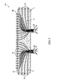
- Fig. 3 is a sectional view illustrating the first embodiment according to the present invention.
- the lighting device with covering body 100 comprises a covering body 1 and a light guiding member 2.
- the covering body 1 is made of an inflexible hard material.
- the covering body 1 can be made of the cement, the soil, or the like.
- the light guiding member 2 is a strap-shaped good light conductor.
- the light guiding member 2 can be made of the optical fiber or the like.
- the covering body 1 has at least one display face 12, and the light guiding member 2 is embedded within the covering body 1 partially (or entirely).
- the light guiding member 2 has a light input terminal 21 and a light output terminal 22, wherein a plurality of the light input terminals 21 are concentratedly arranged in a spot area and are out of the surface of the covering body 1, and the light output terminal 22 is provided on the display face 12.
- a light source body 3 is disposed out of the covering body 1 and connects with each light input terminal 21 of the light guiding member 2.
- a light cover 31 which has light-concentrating effect can be provided on the outer side of the light source body 3 according to the requirement.
- the light source body 3 electrically connects with a direct current transformed and rectified from an external alternating current so as to generate the light.
- the light source body 3 also can electrically connect with an external alternating current to generate the light.
- the light source body 3 also can directly electrically connect with an external alternating current to generate the light.
- the light generated by the light source body 3 is transmitted into the light guiding member 2 from the light input terminal 21. Because of the good light-conductive characteristic of the light guiding member 2, the light is almost no attenuation in the transmission process and radiates from the light output terminal 22 to perform the decoration effect of the point-type light arranged regularly or irregularly.
- the lighting device with covering body 100 can perform the display effect similar to the effect of a plurality of the LED point lights by arranging a plurality of the light output terminals 22 but no heat loss in the transmission process. Only the light source body 3 needs to dissipate heat.
- the light source body 3 is not shown on the display face 12 of the covering body 1, so the design of the display face 12 is easier and more flexible. Also, because of the good structural strength and the good isolation effect of the covering body 1, the light guiding member 2 and the light source body 3 can be protected well.
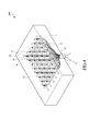
- a lighting device with covering body 100' of the present invention is shown in Fig. 4 .
- the elements of this embodiment illustrated in this Fig. are similar to those in the first embodiment. So the same element of both embodiments is indicated with the same symbol.
- the second embodiment is different from the first embodiment in as follows.
- the lighting device with covering body 100' further comprises a support member 5, and the support member 5 is entirely disposed within a covering body 1" and is fixed by the covering body 1".
- the support member 5 is a net frame structure, and the support member 5 has a plurality of pillars 51 thereon.
- the light guiding member 2 is bound or glued with the pillar 51 by a binding element 6 for fixing the light guiding member 2.
- the light input terminal 21 of the light guiding member 2 is connected with light source body 3, and the light output terminal 22 is provided on the display surface 12 of the covering body 1.
- the light generated by the light source body 3 is transmitted into the light guiding member 2 from the light input terminal 21 to perform the decoration effect of the point-type light arranged regularly or irregularly on the display surface 12.
- a lighting device with covering body 100a' of the present invention is shown in Fig. 5 .
- the elements of this embodiment illustrated in this Fig. are similar to those in the second embodiment. So the same element of both embodiments is indicated with the same symbol.
- the third embodiment is different from the second embodiment in as follows.
- a support member 5a has a plurality of tube pillars 51a thereon.
- the light guiding member 2 passes through tube pillar 51a for fixing the light guiding member 2.
- a lighting device with covering body 100" of the present invention is shown in Fig. 6 .
- the elements of this embodiment illustrated in this Fig. are similar to those in the first embodiment. So the same element of both embodiments is indicated with the same symbol.
- the fourth embodiment is different from the first embodiment in as follows.
- an interior space S1 is provided within a covering body 1".
- a portion of a support member 5" is disposed within the covering body 1" and is fixed by the covering body 1", and another portion of the support member 5" is disposed with the interior space S 1 to support the light source body 3, wherein the light source body 3 is supported by a trough 52 of the support member 5".
- the support member 5" is a dendritic tube.
- the support member 5" has a plurality of branch tubes 53, and the opening 531 of the branch tubes 53 is provided on the display face 12 of the covering body 1".
- the light guiding member 2 is disposed within the support member 5" so as to be protected by the support member 5".
- a light input terminal 21 of the light guiding member 2 is connected with the light source body 3, and a light output terminal 22 of the light guiding member 2 is provided at the opening 531.
- the light emitted form the light source body 3 is transmitted into the light guiding member 2 from the light input terminal 21 to the light output terminal 22 and radiates outward from the light output terminal 22 to perform the decoration effect of the point-type light arranged regularly or irregularly on the display face 12.
- the support member also can be a trough structure, a hive-like structure, a bracket structure, or the like, for supporting or protecting the light guiding member.
- a lighting device with covering body 100a and a lighting device with covering body 100b of the present invention is shown in Fig. 7 .
- the fifth embodiment is an application embodiment by altering the first embodiment (or the second, third, fourth embodiment).
- the lighting device with covering body 100a comprises the covering body 1a and the light guiding member 2, wherein the covering body 1a is shaped into a desk.
- the lighting device with covering body 100b comprising the covering body 1b and the light guiding member 2, wherein the covering body 1b is shaped into a chair.
- the light guiding member 2 is provided within the covering body 1a and the covering body 1b respectively with the methods as same as those of the first embodiment (or the second, third, fourth embodiment).
- the light output terminals 22 are distributed on the surface of the covering body 1a and the covering body 1b respectively, so the covering body 1a' 1b not only have the function as a desk or as a chair but also have the decoration effect of the point-type light arranged on the surface thereon.
- a lighting device with covering body 100c of the present invention is shown in Fig. 8 .
- the sixth embodiment is an application embodiment by altering the first embodiment (or the second, third, fourth embodiment).
- the lighting device with covering body 100c comprises the covering body 1c and the light guiding member 2.
- the covering body 1c can be made to be a convex structure of the edge of the sidewalk nearby the road.
- the light guiding member 2 is provided within the covering body 1c with the methods as same as those of the first embodiment (or the second, third, fourth embodiment).
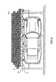
- the light output terminals 22 are distributed on the surface of the covering body 1c, so the covering body 1c not only has a light-distributed surface to divide the sidewalk and the road so as to reduce the traffic accident but also forms the decoration on the roadside to make the street more vivid.
- a lighting device with covering body 100d and a lighting device with covering body 100b of the present invention is shown in Fig. 9 .
- the seventh embodiment is an application embodiment by altering the first embodiment (or the second, third, fourth embodiment).
- the lighting device with covering body 100d comprises the covering body 1d and the light guiding member 2.
- the covering body 1c can be made to be a wall brick.
- the light guiding member 2 is provided within the covering body 1d with the methods as same as those of the first embodiment (or the second, third, fourth embodiment).
- the light output terminals 22 are arranged to form a symbol or a pattern on the particular position distributed on the surface of the covering body 1d according the requirement.
- a plurality of the covering bodies 1d are stacked to form a wall, and the light output terminals 22 are arranged to form a symbol 13 (or to form a pattern).
- the symbol 13 (or the pattern) can be a guide, sign, or a warning to increase the function of the wall.
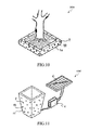
- a lighting device with covering body 100e of the present invention is shown in Fig. 10 .
- the eighth embodiment is an application embodiment by altering the first embodiment (or the second, third, fourth embodiment).
- the lighting device with covering body 100e comprises the covering body 1e and the light guiding member 2.
- the covering body 1e can be made to be a flowerpot.
- the light guiding member 2 is provided within the covering body 1e with the methods as same as those of the first embodiment (or the second, third, fourth embodiment).
- the light output terminals 22 are distributed on the surface of the covering body 1e to make the lighting device with covering body 100e be a decoration flowerpot which has the light points distributed on the surface thereon.
- a lighting device with covering body 100f of the present invention is shown in Fig. 10 .
- the ninth embodiment is an application embodiment by altering the first embodiment (or the second, third, fourth embodiment).
- the lighting device with covering body 100f comprises the covering body 1f and the light guiding member 2.
- the lighting device with covering body 100f further comprises a solar panel 41 and a storage battery 4 with electrical power storage function.
- the covering body 1f can be made to be a large-sized flowerpot.
- the light guiding member 2 is provided within the covering body 1e with the methods as same as those of the first embodiment (or the second, third, fourth embodiment).
- the light output terminals 22 are distributed on the surface of the covering body 1f to make the surface of the lighting device with covering body 100f has the light-distributed decoration effect.
- the storage battery 4 integrates with a power supply managing unit (not shown).
- the power supply managing unit can switch the power supply source according to the outside environment. For example, when the sunlight is strong, the energy of the sunlight absorbed by the solar panel 41 is transmitted to be stored in the storage battery 4; When the outside light is not enough, the requirement energy of the light source body 3 is supplied from the storage battery 4; When the power energy stored in storage battery 4 is empty and the outside light is weak, the light source body 3 is electrically connected with a direct current transformed and rectified from an external alternating current.
- the power source of the lighting device with covering body can be selected form many kinds of the power supply to make the surface of the lighting device with covering body 100f has the light-distributed decoration effect.
- a lighting device with covering body 100g of the present invention is shown in Fig. 12 .
- the tenth embodiment is an application embodiment by altering the first embodiment (or the second, third, fourth embodiment).
- the lighting device with covering body 100g comprising the covering body 1g and the light guiding member 2.
- the covering body 1g is made to be a conic traffic barricade.
- the light guiding member 2 is provided within the covering body 1g with the methods as same as those of the first embodiment (or the second, third, fourth embodiment).
- the light output terminals 22 are distributed on the surface of the covering body 1g.
- a solar panel 41 is provided on the top side of the covering body 1g, and a storage battery is disposed in an interior space within the covering body 1g. When the sunlight is strong, the energy absorbed by the solar panel 41 is transmitted to be stored in the storage battery, so the lighting device with covering body 100g still can generated the distributed light with decoration and warning function on the surface of the covering body 1g even if the sunlight is not enough.
- a lighting device with covering body 100h of the present invention is shown in Fig. 13 .
- the eleventh embodiment is an application embodiment by altering the first embodiment (or the second, third, fourth embodiment).
- the lighting device with covering body 100h comprising the covering body 1h and the light guiding member 2.
- the covering body 1h is made to be a pillar to block the motorcycle and the car at the edge of the sidewalk.
- the light guiding member 2 is provided within the covering body 1h with the methods as same as those of the first embodiment (or the second, third, fourth embodiment).
- the light output terminals 22 are distributed on the surface of the covering body 1g.
- the solar panel 41 is provided on the top side of the covering body 1h, and the storage battery is disposed within the covering body 1h to storage the solar energy absorbed by the solar panel 41. So the lighting device with covering body 100h still can generated the distributed light with decoration and warning function on the surface of the covering body 1h even if the sunlight is not enough.
- the lighting device with covering body of the present invention has industry worth which meets the requirement for a patent.
- the above description should be considered as only the discussion of the preferred embodiments of the present invention.
- a person skilled in the art may make various modifications to the present invention. Those modifications still fall within the spirit and scope defined by the appended claims.
Landscapes
- Engineering & Computer Science (AREA)
- Architecture (AREA)
- Civil Engineering (AREA)
- Structural Engineering (AREA)
- Physics & Mathematics (AREA)
- General Engineering & Computer Science (AREA)
- General Physics & Mathematics (AREA)
- Theoretical Computer Science (AREA)
- Optics & Photonics (AREA)
- Illuminated Signs And Luminous Advertising (AREA)
Abstract
A lighting device with covering body, comprising a covering body and a light guiding member, the covering body has at least one display face, the light guiding member has a light input terminal and a light output terminal, wherein the light guiding member is embedded within the covering body partially or entirely, the light emitted from a light source body is transmitted from the light input terminal to the light output terminal and radiates from the light output terminal on the display face. The light source body not only can be directly electrically connected with an external power source but also can be electrically connected with a storage battery or a solar panel. The power of the light source body can be selected form many kinds of the power supply and can be stored. The light generated from the light source body can be transmitted by the light guiding member to perform the decoration effect of the point-type light on the display surface.
Description
- The present invention relates to a lighting device, and more particularly to a lighting device with covering body.
- The conventional large scale of point-type light source, such as incandescent lamps, has disadvantages including uneven light distribution, large power consumption, and over-concentration of heat being generated. Therefore, it is limited in practice and has some bottleneck difficult to overcome. Other application utilizing a plurality of small scale of point lights source, on the other hand, possesses advantages in even light distribution and being able to generate a better display effect, such as generating various patterns and characters. It therefore replaces the conventional large scale point-type light source, especially in application in traffics signs and guideposts. However, considering a plurality of small scale point-type lights such as LEDs being collected together, since each LED itself is a small scale of heat source, it inevitably generates huge amount of energy of heat. As a measure, there always have to arrange heat dissipating devices, such as heat dissipation plates or electric fans, as basic equipments, around these point-type light sources, in order to prevent from device breakdown, which shortens the life period of the device. But this requirement of the dissipating device indirectly limits the design and modification of the products, and thus further limits the competitive strength of the products.
- Meanwhile, it usually locates the above lighting device, which is arrayed with the plurality of small scale point-type light sources, within a strong material of outer casing, for protection. However the point-type light sources such as LEDs needs to illuminate light directly outward without being covered for sake of better illumination. Even when the above lighting device is merely covered by a transparent casing, such as glass or a transparent plastic plate, it still has drawbacks that these kinds of transparent casings are fragile without having a good protection and needs more energy to illuminate light through the casings.
- Considering the drawback of conventional lighting device of large scale point-type light sources and that of lighting device with a plurality of small scale of point-type light sources, an object of the present invention is to provide a lighting device with covering body that overcomes the defects existing in the prior arts.
- The present invention overcomes the drawbacks of the prior art, and provides a lighting device with covering body, comprising a covering body and a light guide member, the covering body has at least one display face, the light guiding member has a light input terminal and a light output terminal, wherein the light guiding member is embedded within the covering body partially or entirely, the light emitted from a light source body is transmitted from the light input terminal to the light output terminal and radiates from the light output terminal on the display face.
- In a preferred embodiment of the present invention, the covering body is provided with at least one interior space for disposing the light guiding member and/or the light source body therein.
- In a preferred embodiment of the present invention, the number of the light input terminals is plural and the light input terminals are concentratedly arranged within a spot area.
- In a preferred embodiment of the present invention, the number of the light output terminals is plural and the light output terminals are arranged to form a symbol or a pattern.
- In a preferred embodiment of the present invention, the light source body is electrically connected with an external alternating current or with a direct current transformed and rectified from an external alternating current.
- In a preferred embodiment of the present invention, the light source body is electrically connected with a storage battery integrated with a power supply managing unit to store a direct current provided by an external power source and to output the energy while the direct current is breaking off.
- In a preferred embodiment of the present invention, it further comprises a solar panel connected with the power supply managing unit.
- In a preferred embodiment of the present invention, it further comprises a light cover provided on an outer side of the light source body.
- In a preferred embodiment of the present invention, the covering body is made of an inflexible hard material.
- In a preferred embodiment of the present invention, the light guiding member is provided between the light input terminal and the light output terminal with an optical fiber.
- Furthermore, in another preferred embodiment, the present invention overcomes the drawbacks of the prior art, and provides a lighting device with covering body, comprising a covering body and a light guiding member, the covering body has at least one display face, the light guiding member has a light input terminal and a light output terminal, wherein the light guiding member is embedded within the covering body partially or entirely, the light emitted from a light source body is transmitted from the light input terminal to the light output terminal and radiates from the light output terminal on the display face, and the light guiding member and/or the light source body are/is supported by a support member disposed within the covering body partially or entirely.
- In another preferred embodiment of the present invention, the covering body is provided with at least one interior space for disposing the light guiding member, the light source body, and the support member therein.
- In another preferred embodiment of the present invention, the light source electrically connects with a storage battery integrated with a power supply managing unit to store a direct current provided by an external power source and to output the energy while the direct current is breaking off.
- In another preferred embodiment of the present invention, the number of the light output terminals is plural and the light output terminals are arranged to form a symbol or a pattern.
- In another preferred embodiment of the present invention, the number of the light input terminals is plural and the light input terminals are concentratedly arranged within a spot area.
- By means of technical means of this present invention, because the thermal dispersion in the transmission path of the light of the lighting device with covering body would not occur, it is not necessary to install the heat removal means nearby the display position. So the process of the product manufacture can be simplified to reduce the manufacture cost, and the diversification of the design style can be increased, so that the competitive strength of the product increases. The lighting device with covering body is good in structural strength and the situations that the components of the lighting device with covering body are broken owing the water and the dust can be prevented. The power source of the lighting device with covering body can be selected form many kinds of the power supply so that the lighting device with covering body can be applied more commonly.
- The structure and the technical means adopted by the present invention to achieve the above and other objects can be best understood by referring to the following detailed description of the preferred embodiments and the accompanying drawings.
-
-
Fig. 1 is a stereogram illustrating the first embodiment according to the present invention; -
Fig. 2 is an explosion diagram illustrating the first embodiment according to the present invention; -
Fig. 3 is a sectional view illustrating the first embodiment according to the present invention; -
Fig. 4 is a perspective view illustrating the second embodiment according to the present invention; -
Fig. 5 is a partial view illustrating the third embodiment according to the present invention; -
Fig. 6 is a sectional view illustrating the fourth embodiment according to the present invention; -
Fig. 7 is an application gram illustrating the fifth embodiment according to the present invention; -
Fig. 8 is an application gram illustrating the sixth embodiment according to the present invention; -
Fig. 9 is an application gram illustrating the seventh embodiment according to the present invention; -
Fig. 10 is an application gram illustrating the eighth embodiment according to the present invention; -
Fig. 11 is an application gram illustrating the ninth embodiment according to the present invention; -
Fig. 12 is an application gram illustrating the tenth embodiment according to the present invention; -
Fig. 13 is an application gram illustrating the eleventh embodiment according to the present invention; - A lighting device with covering
body 100 of the present invention is shown inFig. 1 ,Fig. 2 , andFig. 3 .Fig. 1 is a stereogram illustrating the first embodiment according to the present invention.Fig. 2 is an explosion diagram illustrating the first embodiment according to the present invention.Fig. 3 is a sectional view illustrating the first embodiment according to the present invention. The lighting device with coveringbody 100 comprises acovering body 1 and alight guiding member 2. In this embodiment, the coveringbody 1 is made of an inflexible hard material. The coveringbody 1 can be made of the cement, the soil, or the like. In this embodiment, thelight guiding member 2 is a strap-shaped good light conductor. Thelight guiding member 2 can be made of the optical fiber or the like. The coveringbody 1 has at least onedisplay face 12, and thelight guiding member 2 is embedded within the coveringbody 1 partially (or entirely). Thelight guiding member 2 has alight input terminal 21 and alight output terminal 22, wherein a plurality of thelight input terminals 21 are concentratedly arranged in a spot area and are out of the surface of the coveringbody 1, and thelight output terminal 22 is provided on thedisplay face 12. - In this embodiment, a
light source body 3 is disposed out of the coveringbody 1 and connects with eachlight input terminal 21 of thelight guiding member 2. Alight cover 31 which has light-concentrating effect can be provided on the outer side of thelight source body 3 according to the requirement. In this embodiment, thelight source body 3 electrically connects with a direct current transformed and rectified from an external alternating current so as to generate the light. Thelight source body 3 also can electrically connect with an external alternating current to generate the light. Thelight source body 3 also can directly electrically connect with an external alternating current to generate the light. The light generated by thelight source body 3 is transmitted into thelight guiding member 2 from thelight input terminal 21. Because of the good light-conductive characteristic of thelight guiding member 2, the light is almost no attenuation in the transmission process and radiates from thelight output terminal 22 to perform the decoration effect of the point-type light arranged regularly or irregularly. - The lighting device with covering
body 100 can perform the display effect similar to the effect of a plurality of the LED point lights by arranging a plurality of thelight output terminals 22 but no heat loss in the transmission process. Only thelight source body 3 needs to dissipate heat. Thelight source body 3 is not shown on thedisplay face 12 of the coveringbody 1, so the design of thedisplay face 12 is easier and more flexible. Also, because of the good structural strength and the good isolation effect of the coveringbody 1, thelight guiding member 2 and thelight source body 3 can be protected well. - A lighting device with covering body 100' of the present invention is shown in
Fig. 4 . The elements of this embodiment illustrated in this Fig. are similar to those in the first embodiment. So the same element of both embodiments is indicated with the same symbol. The second embodiment is different from the first embodiment in as follows. In this embodiment, the lighting device with covering body 100' further comprises asupport member 5, and thesupport member 5 is entirely disposed within a coveringbody 1" and is fixed by the coveringbody 1". In this embodiment, thesupport member 5 is a net frame structure, and thesupport member 5 has a plurality ofpillars 51 thereon. Thelight guiding member 2 is bound or glued with thepillar 51 by abinding element 6 for fixing thelight guiding member 2. Thelight input terminal 21 of thelight guiding member 2 is connected withlight source body 3, and thelight output terminal 22 is provided on thedisplay surface 12 of the coveringbody 1. The light generated by thelight source body 3 is transmitted into thelight guiding member 2 from thelight input terminal 21 to perform the decoration effect of the point-type light arranged regularly or irregularly on thedisplay surface 12. - A lighting device with covering
body 100a' of the present invention is shown inFig. 5 . The elements of this embodiment illustrated in this Fig. are similar to those in the second embodiment. So the same element of both embodiments is indicated with the same symbol. The third embodiment is different from the second embodiment in as follows. In this embodiment, asupport member 5a has a plurality oftube pillars 51a thereon. Thelight guiding member 2 passes throughtube pillar 51a for fixing thelight guiding member 2. - A lighting device with covering
body 100" of the present invention is shown inFig. 6 . The elements of this embodiment illustrated in this Fig. are similar to those in the first embodiment. So the same element of both embodiments is indicated with the same symbol. The fourth embodiment is different from the first embodiment in as follows. In this embodiment, an interior space S1 is provided within a coveringbody 1". A portion of asupport member 5" is disposed within the coveringbody 1" and is fixed by the coveringbody 1", and another portion of thesupport member 5" is disposed with theinterior space S 1 to support thelight source body 3, wherein thelight source body 3 is supported by atrough 52 of thesupport member 5". In this embodiment, thesupport member 5" is a dendritic tube. Thesupport member 5" has a plurality ofbranch tubes 53, and theopening 531 of thebranch tubes 53 is provided on thedisplay face 12 of the coveringbody 1". Thelight guiding member 2 is disposed within thesupport member 5" so as to be protected by thesupport member 5". Alight input terminal 21 of thelight guiding member 2 is connected with thelight source body 3, and alight output terminal 22 of thelight guiding member 2 is provided at theopening 531. The light emitted form thelight source body 3 is transmitted into thelight guiding member 2 from thelight input terminal 21 to thelight output terminal 22 and radiates outward from thelight output terminal 22 to perform the decoration effect of the point-type light arranged regularly or irregularly on thedisplay face 12. - In addition to the embodiments mentioned above, the support member also can be a trough structure, a hive-like structure, a bracket structure, or the like, for supporting or protecting the light guiding member.
- A lighting device with covering
body 100a and a lighting device with coveringbody 100b of the present invention is shown inFig. 7 . The fifth embodiment is an application embodiment by altering the first embodiment (or the second, third, fourth embodiment). In this embodiment, the lighting device with coveringbody 100a comprises the covering body 1a and thelight guiding member 2, wherein the covering body 1a is shaped into a desk. The lighting device with coveringbody 100b comprising the covering body 1b and thelight guiding member 2, wherein the covering body 1b is shaped into a chair. Thelight guiding member 2 is provided within the covering body 1a and the covering body 1b respectively with the methods as same as those of the first embodiment (or the second, third, fourth embodiment). Thelight output terminals 22 are distributed on the surface of the covering body 1a and the covering body 1b respectively, so the covering body 1a' 1b not only have the function as a desk or as a chair but also have the decoration effect of the point-type light arranged on the surface thereon. - A lighting device with covering
body 100c of the present invention is shown inFig. 8 . The sixth embodiment is an application embodiment by altering the first embodiment (or the second, third, fourth embodiment). In this embodiment, the lighting device with coveringbody 100c comprises the covering body 1c and thelight guiding member 2. The covering body 1c can be made to be a convex structure of the edge of the sidewalk nearby the road. Thelight guiding member 2 is provided within the covering body 1c with the methods as same as those of the first embodiment (or the second, third, fourth embodiment). Thelight output terminals 22 are distributed on the surface of the covering body 1c, so the covering body 1c not only has a light-distributed surface to divide the sidewalk and the road so as to reduce the traffic accident but also forms the decoration on the roadside to make the street more vivid. - A lighting device with covering
body 100d and a lighting device with coveringbody 100b of the present invention is shown inFig. 9 . The seventh embodiment is an application embodiment by altering the first embodiment (or the second, third, fourth embodiment). In this embodiment, the lighting device with coveringbody 100d comprises the covering body 1d and thelight guiding member 2. The covering body 1c can be made to be a wall brick. Thelight guiding member 2 is provided within the covering body 1d with the methods as same as those of the first embodiment (or the second, third, fourth embodiment). Thelight output terminals 22 are arranged to form a symbol or a pattern on the particular position distributed on the surface of the covering body 1d according the requirement. In this embodiment, a plurality of the covering bodies 1d are stacked to form a wall, and thelight output terminals 22 are arranged to form a symbol 13 (or to form a pattern). The symbol 13 (or the pattern) can be a guide, sign, or a warning to increase the function of the wall. - A lighting device with covering
body 100e of the present invention is shown inFig. 10 . The eighth embodiment is an application embodiment by altering the first embodiment (or the second, third, fourth embodiment). In this embodiment, the lighting device with coveringbody 100e comprises the covering body 1e and thelight guiding member 2. The covering body 1e can be made to be a flowerpot. Thelight guiding member 2 is provided within the covering body 1e with the methods as same as those of the first embodiment (or the second, third, fourth embodiment). Thelight output terminals 22 are distributed on the surface of the covering body 1e to make the lighting device with coveringbody 100e be a decoration flowerpot which has the light points distributed on the surface thereon. - A lighting device with covering
body 100f of the present invention is shown inFig. 10 . The ninth embodiment is an application embodiment by altering the first embodiment (or the second, third, fourth embodiment). In this embodiment, the lighting device with coveringbody 100f comprises the covering body 1f and thelight guiding member 2. The lighting device with coveringbody 100f further comprises asolar panel 41 and a storage battery 4 with electrical power storage function. The covering body 1f can be made to be a large-sized flowerpot. Thelight guiding member 2 is provided within the covering body 1e with the methods as same as those of the first embodiment (or the second, third, fourth embodiment). Thelight output terminals 22 are distributed on the surface of the covering body 1f to make the surface of the lighting device with coveringbody 100f has the light-distributed decoration effect. - In this embodiment, the storage battery 4 integrates with a power supply managing unit (not shown). The power supply managing unit can switch the power supply source according to the outside environment. For example, when the sunlight is strong, the energy of the sunlight absorbed by the
solar panel 41 is transmitted to be stored in the storage battery 4; When the outside light is not enough, the requirement energy of thelight source body 3 is supplied from the storage battery 4; When the power energy stored in storage battery 4 is empty and the outside light is weak, thelight source body 3 is electrically connected with a direct current transformed and rectified from an external alternating current. The power source of the lighting device with covering body can be selected form many kinds of the power supply to make the surface of the lighting device with coveringbody 100f has the light-distributed decoration effect. - A lighting device with covering
body 100g of the present invention is shown inFig. 12 . The tenth embodiment is an application embodiment by altering the first embodiment (or the second, third, fourth embodiment). In this embodiment, the lighting device with coveringbody 100g comprising the covering body 1g and thelight guiding member 2. The covering body 1g is made to be a conic traffic barricade. Thelight guiding member 2 is provided within the covering body 1g with the methods as same as those of the first embodiment (or the second, third, fourth embodiment). Thelight output terminals 22 are distributed on the surface of the covering body 1g. Asolar panel 41 is provided on the top side of the covering body 1g, and a storage battery is disposed in an interior space within the covering body 1g. When the sunlight is strong, the energy absorbed by thesolar panel 41 is transmitted to be stored in the storage battery, so the lighting device with coveringbody 100g still can generated the distributed light with decoration and warning function on the surface of the covering body 1g even if the sunlight is not enough. - A lighting device with covering
body 100h of the present invention is shown inFig. 13 . The eleventh embodiment is an application embodiment by altering the first embodiment (or the second, third, fourth embodiment). In this embodiment, the lighting device with coveringbody 100h comprising the covering body 1h and thelight guiding member 2. The covering body 1h is made to be a pillar to block the motorcycle and the car at the edge of the sidewalk. Thelight guiding member 2 is provided within the covering body 1h with the methods as same as those of the first embodiment (or the second, third, fourth embodiment). Thelight output terminals 22 are distributed on the surface of the covering body 1g. Thesolar panel 41 is provided on the top side of the covering body 1h, and the storage battery is disposed within the covering body 1h to storage the solar energy absorbed by thesolar panel 41. So the lighting device with coveringbody 100h still can generated the distributed light with decoration and warning function on the surface of the covering body 1h even if the sunlight is not enough. - As can be appreciated from the above embodiments, the lighting device with covering body of the present invention has industry worth which meets the requirement for a patent. The above description should be considered as only the discussion of the preferred embodiments of the present invention. However, a person skilled in the art may make various modifications to the present invention. Those modifications still fall within the spirit and scope defined by the appended claims.
Claims (15)
- A lighting device with covering body, comprising:a covering body having at least one display face; anda light guiding member having a light input terminal and a light output terminal,wherein the light guiding member is embedded within the covering body partially or entirely, the light emitted from a light source body is transmitted from the light input terminal to the light output terminal and radiates from the light output terminal on the display face.
- The lighting device with covering body as claimed in claim 1, wherein the covering body is provided with at least one interior space for disposing the light guiding member and/or the light source body therein.
- The lighting device with covering body as claimed in claim 1 or 2, wherein the number of light input terminals is plural and the light input terminals are concentratedly arranged within a spot area.
- The lighting device with covering body as claimed in any of the preceding claims, wherein the number of light output terminals is plural and the light output terminals are arranged to form a symbol or a pattern.
- The lighting device with covering body as claimed in any of the preceding claims, wherein the light source body is electrically connected with an external alternating current or with a direct current transformed and rectified from an external alternating current.
- The lighting device with covering body as claimed any of the preceding claims, wherein the light source body is electrically connected with a storage battery integrated with a power supply managing unit to store a direct current provided by an external power source and to output the energy while the direct current is breaking off.
- The lighting device with covering body as claimed in claim 6, further comprising a solar panel connected with the power supply managing unit.
- The lighting device with covering body as claimed any of the preceding claims, further comprising a light cover provided on an outer side of the light source body.
- The lighting device with covering body as claimed any of the preceding claims, wherein the covering body is made of an inflexible hard material.
- The lighting device with covering body as claimed any of the preceding claims, wherein the light guiding member is provided between the light input terminal and the light output terminal with an optical fiber.
- A lighting device with covering body, comprising:a covering body having at least one display face; anda light guiding member having a light input terminal and a light output terminal,wherein the light guiding member is embedded within the covering body partially or entirely, the light emitted from a light source body is transmitted from the light input terminal to the light output terminal and radiates from the light output terminal on the display face, and the light guiding member and/or the light source body are/is supported by a support member disposed within the covering body partially or entirely.
- The lighting device with covering body as claimed in claim 11, wherein the covering body is provided with at least one interior space for disposing the light guiding member, the light source body, and the support member therein.
- The lighting device with covering body as claimed in claim 11 or 12, wherein the light source electrically connects with a storage battery integrated with a power supply managing unit to store a direct current provided by an external power source and to output the energy while the direct current is breaking off.
- The lighting device with covering body as claimed in any of the preceding claims 11 to 13, wherein the number of the light output terminals is plural and the light output terminals are arranged to form a symbol or a pattern.
- The lighting device with covering body as claimed in any of the preceding claims 11 to 14, wherein the number of the light input terminals is plural and the light input terminals are concentratedly arranged within a spot area.
Priority Applications (1)
| Application Number | Priority Date | Filing Date | Title |
|---|---|---|---|
| EP12151186.9A EP2615366A1 (en) | 2012-01-14 | 2012-01-14 | Lighting device with covering body |
Applications Claiming Priority (1)
| Application Number | Priority Date | Filing Date | Title |
|---|---|---|---|
| EP12151186.9A EP2615366A1 (en) | 2012-01-14 | 2012-01-14 | Lighting device with covering body |
Publications (1)
| Publication Number | Publication Date |
|---|---|
| EP2615366A1 true EP2615366A1 (en) | 2013-07-17 |
Family
ID=45524331
Family Applications (1)
| Application Number | Title | Priority Date | Filing Date |
|---|---|---|---|
| EP12151186.9A Withdrawn EP2615366A1 (en) | 2012-01-14 | 2012-01-14 | Lighting device with covering body |
Country Status (1)
| Country | Link |
|---|---|
| EP (1) | EP2615366A1 (en) |
Cited By (4)
| Publication number | Priority date | Publication date | Assignee | Title |
|---|---|---|---|---|
| CN108005295A (en) * | 2017-10-31 | 2018-05-08 | 重庆世纪之光科技实业有限公司 | Transparent brick and preparation method thereof |
| CN111561124A (en) * | 2020-04-30 | 2020-08-21 | 北京数字博文科技发展有限公司 | High-strength spliced light-emitting platform |
| WO2021144580A1 (en) * | 2020-01-17 | 2021-07-22 | Heaton Luke Latham Moorhouse | A light transmissive composite component and method of forming the component |
| US11639791B2 (en) * | 2019-09-20 | 2023-05-02 | The Swatch Group Research And Development Ltd | Decorative item with a light effect |
Citations (7)
| Publication number | Priority date | Publication date | Assignee | Title |
|---|---|---|---|---|
| US4807092A (en) * | 1987-07-02 | 1989-02-21 | Yasuo Hasegawa | Optical decoration system |
| GB2364265A (en) * | 2000-06-23 | 2002-01-23 | Pullen Lee Jason | Moulded article |
| US20040032748A1 (en) * | 2002-08-14 | 2004-02-19 | Gilles Trudeau | Illuminating structure |
| US20050057945A1 (en) * | 2003-09-13 | 2005-03-17 | Pipo Walter E. | Self-illuminating fabricated solid material objects |
| CN2718600Y (en) * | 2004-05-10 | 2005-08-17 | 纬创资通股份有限公司 | Light guide column made of optical fiber |
| GB2470888A (en) * | 2008-12-31 | 2010-12-15 | Katherine Viola Buzsaki | Illumination of woven fibre optic decorations using a plurality of light emitting diodes |
| WO2011002159A2 (en) * | 2009-06-30 | 2011-01-06 | (주) 에스엘테크 | Road sign employing optical fibers |
-
2012
- 2012-01-14 EP EP12151186.9A patent/EP2615366A1/en not_active Withdrawn
Patent Citations (7)
| Publication number | Priority date | Publication date | Assignee | Title |
|---|---|---|---|---|
| US4807092A (en) * | 1987-07-02 | 1989-02-21 | Yasuo Hasegawa | Optical decoration system |
| GB2364265A (en) * | 2000-06-23 | 2002-01-23 | Pullen Lee Jason | Moulded article |
| US20040032748A1 (en) * | 2002-08-14 | 2004-02-19 | Gilles Trudeau | Illuminating structure |
| US20050057945A1 (en) * | 2003-09-13 | 2005-03-17 | Pipo Walter E. | Self-illuminating fabricated solid material objects |
| CN2718600Y (en) * | 2004-05-10 | 2005-08-17 | 纬创资通股份有限公司 | Light guide column made of optical fiber |
| GB2470888A (en) * | 2008-12-31 | 2010-12-15 | Katherine Viola Buzsaki | Illumination of woven fibre optic decorations using a plurality of light emitting diodes |
| WO2011002159A2 (en) * | 2009-06-30 | 2011-01-06 | (주) 에스엘테크 | Road sign employing optical fibers |
Cited By (4)
| Publication number | Priority date | Publication date | Assignee | Title |
|---|---|---|---|---|
| CN108005295A (en) * | 2017-10-31 | 2018-05-08 | 重庆世纪之光科技实业有限公司 | Transparent brick and preparation method thereof |
| US11639791B2 (en) * | 2019-09-20 | 2023-05-02 | The Swatch Group Research And Development Ltd | Decorative item with a light effect |
| WO2021144580A1 (en) * | 2020-01-17 | 2021-07-22 | Heaton Luke Latham Moorhouse | A light transmissive composite component and method of forming the component |
| CN111561124A (en) * | 2020-04-30 | 2020-08-21 | 北京数字博文科技发展有限公司 | High-strength spliced light-emitting platform |
Similar Documents
| Publication | Publication Date | Title |
|---|---|---|
| CA2749166C (en) | Lighting apparatus using light-emitting diode | |
| KR20170073536A (en) | Multifunction LED street light device for stability of installation | |
| WO2003091623A1 (en) | Lighting apparatus | |
| WO2011046410A3 (en) | Intelligent streetlamp system | |
| KR20140079932A (en) | Lamp for vehicle | |
| KR20230174135A (en) | Road marker | |
| CN102042516A (en) | Lighting device | |
| WO2011002159A2 (en) | Road sign employing optical fibers | |
| KR101561810B1 (en) | Traffic sign board apparatus having solar cells of traffic sign shape | |
| KR102676158B1 (en) | Optical Fiber Road Stud | |
| EP2375130A1 (en) | Lighting module for tunnel, road or street light | |
| AU2015299531A1 (en) | Mark and sign lighting device, method and system | |
| CN205026517U (en) | Modular guardrail lamp | |
| KR101471389B1 (en) | Apparatus of surface light source for signboard | |
| KR101382110B1 (en) | Led traffic signal display equipment having a heatsink and hinge | |
| JP3186591U (en) | Lighting device with information display | |
| JP2011214361A (en) | Secondary concrete product with light emission function | |
| JP6901116B2 (en) | lighting equipment | |
| EP3359739B1 (en) | Illumination system for a safety barrier, safety barrier therewith and kit of parts | |
| KR101573876B1 (en) | LED display board | |
| KR101003595B1 (en) | Hicks | |
| ATE426877T1 (en) | SIGNAL LAMP | |
| CN210886988U (en) | Luminous reflection of light traffic signboard | |
| WO2012165655A1 (en) | Charging state displaying device | |
| CN201672416U (en) | Improved structure of door lamp for vehicle |
Legal Events
| Date | Code | Title | Description |
|---|---|---|---|
| PUAI | Public reference made under article 153(3) epc to a published international application that has entered the european phase |
Free format text: ORIGINAL CODE: 0009012 |
|
| AK | Designated contracting states |
Kind code of ref document: A1 Designated state(s): AL AT BE BG CH CY CZ DE DK EE ES FI FR GB GR HR HU IE IS IT LI LT LU LV MC MK MT NL NO PL PT RO RS SE SI SK SM TR |
|
| AX | Request for extension of the european patent |
Extension state: BA ME |
|
| STAA | Information on the status of an ep patent application or granted ep patent |
Free format text: STATUS: THE APPLICATION IS DEEMED TO BE WITHDRAWN |
|
| 18D | Application deemed to be withdrawn |
Effective date: 20140118 |