EP2615345A2 - Overshaft fluid transfer coupling and mounting arrangement - Google Patents
Overshaft fluid transfer coupling and mounting arrangement Download PDFInfo
- Publication number
- EP2615345A2 EP2615345A2 EP12199145.9A EP12199145A EP2615345A2 EP 2615345 A2 EP2615345 A2 EP 2615345A2 EP 12199145 A EP12199145 A EP 12199145A EP 2615345 A2 EP2615345 A2 EP 2615345A2
- Authority
- EP
- European Patent Office
- Prior art keywords
- fluid
- passage
- coupling
- housing
- sleeve
- Prior art date
- Legal status (The legal status is an assumption and is not a legal conclusion. Google has not performed a legal analysis and makes no representation as to the accuracy of the status listed.)
- Granted
Links
Images




Classifications
-
- F—MECHANICAL ENGINEERING; LIGHTING; HEATING; WEAPONS; BLASTING
- F16—ENGINEERING ELEMENTS AND UNITS; GENERAL MEASURES FOR PRODUCING AND MAINTAINING EFFECTIVE FUNCTIONING OF MACHINES OR INSTALLATIONS; THERMAL INSULATION IN GENERAL
- F16L—PIPES; JOINTS OR FITTINGS FOR PIPES; SUPPORTS FOR PIPES, CABLES OR PROTECTIVE TUBING; MEANS FOR THERMAL INSULATION IN GENERAL
- F16L39/00—Joints or fittings for double-walled or multi-channel pipes or pipe assemblies
- F16L39/04—Joints or fittings for double-walled or multi-channel pipes or pipe assemblies allowing adjustment or movement
-
- Y—GENERAL TAGGING OF NEW TECHNOLOGICAL DEVELOPMENTS; GENERAL TAGGING OF CROSS-SECTIONAL TECHNOLOGIES SPANNING OVER SEVERAL SECTIONS OF THE IPC; TECHNICAL SUBJECTS COVERED BY FORMER USPC CROSS-REFERENCE ART COLLECTIONS [XRACs] AND DIGESTS
- Y10—TECHNICAL SUBJECTS COVERED BY FORMER USPC
- Y10T—TECHNICAL SUBJECTS COVERED BY FORMER US CLASSIFICATION
- Y10T29/00—Metal working
- Y10T29/49—Method of mechanical manufacture
- Y10T29/494—Fluidic or fluid actuated device making
Definitions
- This disclosure relates to an overshaft fluid transfer coupling and mounting arrangement for same
- Some machines include rotating hollow shafts through which fluid is transferred within the interior of the shaft. Often the fluid may be communicated from one end of the shaft to the other end of the shaft. However, some applications, which include spatial constraints at the shaft ends, may require fluid transfer through the radial wall of the shaft.
- a fluid coupling is arranged over the shaft and concentric annuli between close tolerance lands provide a transfer path between the fluid coupling and the rotating shaft.
- a bolted flange joint typically fastens the fluid coupling to the machine's housing.
- a fluid transfer coupling arrangement in one example embodiment, includes a hollow shaft that is arranged in a housing and rotatable about an axis.
- the hollow shaft is provided by a wall having radially spaced interior and exterior surface, A first passage extends through the shaft wall and is configured to communicate fluid between the interior and exterior surfaces.
- a fluid coupling is positioned about the exterior surface and straddles the first passage. The fluid coupling creates a second passage that is in alignment with the first passage and provides fluid communication.
- the fluid coupling includes a locating feature configured to permit compliance and radial movement of the fluid coupling relative to the housing.
- the fluid transfer coupling has a sleeve with an interior surface providing sealing surfaces axially spaced from one another.
- the first and second sealing surfaces bound a portion of the second passages created between sleeve and shaft.
- a port is in fluid communication with the second passage portion,
- the locating feature configured to permit the sleeve to float is provided by a retaining ring on shaft exterior and a tab extending into the housing 40 from the exterior surface of the sleeve.
- An example method of assembly of the fluid transfer coupling arrangement includes installing a sleeve about the exterior surface of the hollow shaft to provide a shaft assembly, The shaft assembly is inserted into the housing. The locating feature of the sleeve is positioned relative to a corresponding locating feature on the housing. The sleeve is permitted to float radially relative to the housing.
- FIG 1 schematically illustrates an exemplary high speed vertical takeoff and landing (VTOL) rotary-wing aircraft 10 having a counter-rotating, coaxial rotor system 12 which rotates about an axis of rotation A.
- the aircraft 10 includes an airframe 14 that supports a drive system 16 ( Figure 2 ), which generally includes the rotor system 12, a powertrain system 24, a power plant system 26, and a secondary thrust system 30.
- VTOL vertical takeoff and landing
- the secondary thrust system 30 provides secondary thrust generally parallel to an aircraft longitudinal axis L while the main rotor system 12 operates in an unloaded reverse flow state during a high-speed forward flight profile
- a particular aircraft configuration is illustrated and described in the disclosed embodiment, other configurations and/or machines, such as high speed compound rotary-wing aircraft with supplemental secondary thrust systems, dual contra-rotating, coaxial rotor system aircraft, turbo-props, tilt-rotor, tilt-wing aircraft and non-aircraft applications will also benefit from the disclosed planetary gear system.
- the main rotor system 12 includes an upper rotor system 18A and a lower rotor system 18B.
- Each rotor system 18A, 18B includes multiple rotor blades 20 mounted to a respective rotor hub 22A, 22B for rotation about a rotor axis of rotation A. Any number of blades 20 may be used with the rotor system 12.
- the powertrain system 24 interconnects the power plant system 26, the rotor system 12 and the secondary thrust system 30.
- the powertrain system 24 may include various gear systems such as main and combiner gearboxes,
- the power plant system 26 generates the power available for flight operations to power the main rotor system 12 and the secondary thrust system 30 through the powertrain system 24.
- the power plant system 26 in the disclosed, non-limiting embodiment includes two engine packages ENG1, ENG2, however, single engine systems as well as multi-engine systems will also benefit from the disclosed planetary gear system,
- the secondary thrust system 30 in one non-limiting embodiment may be mounted to the rear of the airframe 14 transverse to the axis of rotation A with a rotational axis T thereof oriented substantially horizontal and parallel to an aircraft longitudinal axis L to provide thrust for high-speed flight, It should be understood that other configurations of the secondary thrust system 30 such as a propeller system mounted to each side of the airframe, a lift fan system, or other system alternatively may be utilized.
- the secondary thrust system 30 includes a pusher propeller system 32 including pusher blades 34. Power is transmitted from an input shaft 42 of the drive system 16 through a gearbox 38 to an output shaft 44 to rotationally drive the pusher propeller system 32.
- a fluid transfer coupling sleeve 46 is used within the gearbox 38.
- the fluid transfer coupling 46 includes a hollow shaft 50 that is arranged in the housing 40 and rotatable about an axis S.
- an input member 48 which is operatively coupled to the input shaft 42, is connected to the hollow shaft 50 by a splined connection 86.
- the hollow shaft 50 is supported for rotation relative to the housing 40 by roller bearings 54 and a thrust bearing 56 in the example.
- An output member 52 is provided at one end of the hollow shaft 50, for example, and is operatively coupled to the output shaft 44.
- the hollow shaft 50 has a wall 58 with radially spaced interior and exterior surfaces 60, 62.
- a first passage 88 extends through the wall 58 and is configured to communicate fluid between the interior and exterior surfaces 60, 62.
- a sleeve 64 provides the fluid coupling onto the hollow shaft 50. Leakage is controlled by the use of close-tolerance lands at localized portions of the exterior surface 62 and the interior surfaces of the sleeve 64. Annular voids created between the close tolerance seal lands provides a second passage 90, which is annular, that aligns with first, passage 88 to transfer fluid (fluid flow shown by small arrows) between an externally mounted controller device 110 and the interior of the hollow rotating shaft 50.
- first and second members 82, 84 may be nested within the interior of the hollow shaft 50 and provide an annular passage 83 that communicates another fluid flow within the hollow shaft 50.
- the fluid actuates a two-way hydraulic cylinder (not shown) mounted on the output shaft 52.
- the sleeve 64 is arranged axially at mid-span between the roller bearings 54, Manufacturing runouts, bearing clearances and induced bending moments on the shaft flange 52 may result in the hollow shaft 50 having some undesired radial movements in the area of the coupling sleeve 64.
- the fluid coupling 46 includes one or more locating features that maintain the sleeve 64 in desired circumferential, axial and radial positions while permitting some radial movement of the sleeve 64 to maintain a uniform gap and desired sealing engagement with the hollow shaft 50.
- the sleeve 64 includes a locating feature, provided by a tab 66 in one example, configured to permit nominal radial movement of the sleeve 64 relative to the housing 40.
- the tab 66 which acts as a key in the example, is received in a slot 70 provided by a boss 68 in the housing 40.
- a nominally suitable tangential clearance is preserved in that key and slot arrangement.
- a radial clearance 112 is provided between the housing 40 and tab 66 to permit the sleeve 64 to float, best shown in Figure 5B .
- the tab 66 extends an axial length T and includes a circumferential width W, best shown in Figure 5A . The clearances aid in assembly and allow compliance of the sleeve unit during operation.
- the sleeve 64 includes a first side 74.
- the hollow shaft 50 has a groove 78 that receives a retaining ring 80, which provides an axial stop on the shaft body.
- the tab 66 is flush with a second side 76 of the sleeve 64.
- the boss 68 provides an axial stop 72 for the sleeve 64,
- the boss 68 and the retaining ring 80 axially locate the sleeve 64 within an allowable set of operating clearances.
- the sleeve 64 has an interior surface 92 providing first and second sealing surfaces. These surfaces can include features that improve sealing capability, such as grooves 94, axially spaced from the edges and one another, The seal lands bound the annular passage 90.
- the sleeve 64 includes a boss 98 that receives a transfer tube 102, for example, which provides a port 100 (two shown).
- the port 100 supplies fluid communication with the annulus passage 90.
- the housing 40 includes a clearance hole 104 (two exist, one is shown), best shown in Figures 5A and 5B .
- a transfer tube 102 extends through each hole 104 and is removably received in the port 100.
- a controller 110 is secured to the housing 40 over the tubas 102 and selectively regulates fluid flow and pressure into the fluid coupling 46, Three seals 106, 108, and 114 respectively seal between the transfer tube 102, the sleeve 64, housing 40, and controller 110. . In this manner, and with its extended length and tangential entry into sleeve, the transfer tube 102 further accommodates some radial movement of the sleeve 64 during operation.
- FIG. 3 An example method of assembly of the fluid transfer coupling 46 is schematically shown in Figure 3 by the large block arrows.
- the assembly method includes installing the sleeve 64 about the exterior surface 62 of the hollow shaft 50 to provide a shaft assembly.
- the sleeve 64 slid over the hollow shaft 50 until the first side 74 abuts the retaining ring 80.
- the shaft assembly is inserted into the housing 40 until the thrust bearing 56 bottoms on housing 40.
- the tab 66 is positioned relative to the corresponding slot 70, where the second side 76 maintains a nominal axial clearance to the stop 72.
- the sleeve 64 is permitted to float radially relative to the housing 40 due to the radial clearance 112 ( Fig. 5B ).
- the transfer tubes 102 are inserted through the holes 104 and into the ports 100.
- the actuator 110 is secured to the housing 40 to capture the tubes 102. In this manner, the short, direct control loop is provided between the actuator and the hollow shaft 50 and components fluidly connected to the hollow shaft 50.
Landscapes
- Engineering & Computer Science (AREA)
- General Engineering & Computer Science (AREA)
- Mechanical Engineering (AREA)
- Joints Allowing Movement (AREA)
- Quick-Acting Or Multi-Walled Pipe Joints (AREA)
Abstract
Description
- This disclosure relates to an overshaft fluid transfer coupling and mounting arrangement for same,
- Some machines include rotating hollow shafts through which fluid is transferred within the interior of the shaft. Often the fluid may be communicated from one end of the shaft to the other end of the shaft. However, some applications, which include spatial constraints at the shaft ends, may require fluid transfer through the radial wall of the shaft. A fluid coupling is arranged over the shaft and concentric annuli between close tolerance lands provide a transfer path between the fluid coupling and the rotating shaft. A bolted flange joint typically fastens the fluid coupling to the machine's housing.
- In one example embodiment, a fluid transfer coupling arrangement includes a hollow shaft that is arranged in a housing and rotatable about an axis. The hollow shaft is provided by a wall having radially spaced interior and exterior surface, A first passage extends through the shaft wall and is configured to communicate fluid between the interior and exterior surfaces. A fluid coupling is positioned about the exterior surface and straddles the first passage. The fluid coupling creates a second passage that is in alignment with the first passage and provides fluid communication. The fluid coupling includes a locating feature configured to permit compliance and radial movement of the fluid coupling relative to the housing.
- In one example, the fluid transfer coupling has a sleeve with an interior surface providing sealing surfaces axially spaced from one another. The first and second sealing surfaces bound a portion of the second passages created between sleeve and shaft. A port is in fluid communication with the second passage portion, The locating feature configured to permit the sleeve to float is provided by a retaining ring on shaft exterior and a tab extending into the
housing 40 from the exterior surface of the sleeve. - An example method of assembly of the fluid transfer coupling arrangement includes installing a sleeve about the exterior surface of the hollow shaft to provide a shaft assembly, The shaft assembly is inserted into the housing. The locating feature of the sleeve is positioned relative to a corresponding locating feature on the housing. The sleeve is permitted to float radially relative to the housing.
- The disclosure can be further understood by reference to the following detailed description when considered in connection with the accompanying drawings.
-
Figure 1 is a general schematic view of an exemplary rotary wing aircraft embodiment for use with the present disclosure. -
Figure 2 is a general schematic view of a drive system for the rotary wing aircraft. -
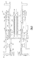
Figure 3 is a cross-sectional view of a shaft assembly relating to an assembly procedure. -
Figure 4 is a cross-sectional view of the shaft assembly ofFigure 3 illustrated in more detail. -
Figure 5A is a perspective view of a fluid transfer coupling depicted schematically within a housing profile, -
Figure 5B is a cross-sectional true view of the fluid transfer coupling shown inFigure 5A in the housing. -
Figure 1 schematically illustrates an exemplary high speed vertical takeoff and landing (VTOL) rotary-wing aircraft 10 having a counter-rotating,coaxial rotor system 12 which rotates about an axis of rotation A. Theaircraft 10 includes anairframe 14 that supports a drive system 16 (Figure 2 ), which generally includes therotor system 12, apowertrain system 24, apower plant system 26, and asecondary thrust system 30. Thesecondary thrust system 30 provides secondary thrust generally parallel to an aircraft longitudinal axis L while themain rotor system 12 operates in an unloaded reverse flow state during a high-speed forward flight profile, Although a particular aircraft configuration is illustrated and described in the disclosed embodiment, other configurations and/or machines, such as high speed compound rotary-wing aircraft with supplemental secondary thrust systems, dual contra-rotating, coaxial rotor system aircraft, turbo-props, tilt-rotor, tilt-wing aircraft and non-aircraft applications will also benefit from the disclosed planetary gear system. - The
main rotor system 12 includes anupper rotor system 18A and alower rotor system 18B. Eachrotor system multiple rotor blades 20 mounted to arespective rotor hub blades 20 may be used with therotor system 12. - With reference to
Figure 2 , thepowertrain system 24 interconnects thepower plant system 26, therotor system 12 and thesecondary thrust system 30. Thepowertrain system 24 may include various gear systems such as main and combiner gearboxes, Thepower plant system 26 generates the power available for flight operations to power themain rotor system 12 and thesecondary thrust system 30 through thepowertrain system 24. Thepower plant system 26 in the disclosed, non-limiting embodiment includes two engine packages ENG1, ENG2, however, single engine systems as well as multi-engine systems will also benefit from the disclosed planetary gear system, - The
secondary thrust system 30 in one non-limiting embodiment may be mounted to the rear of theairframe 14 transverse to the axis of rotation A with a rotational axis T thereof oriented substantially horizontal and parallel to an aircraft longitudinal axis L to provide thrust for high-speed flight, It should be understood that other configurations of thesecondary thrust system 30 such as a propeller system mounted to each side of the airframe, a lift fan system, or other system alternatively may be utilized. In this disclosed, non-limiting embodiment, thesecondary thrust system 30 includes apusher propeller system 32 includingpusher blades 34. Power is transmitted from aninput shaft 42 of thedrive system 16 through agearbox 38 to anoutput shaft 44 to rotationally drive thepusher propeller system 32. - In one example embodiment shown in
Figures 3 and4 , a fluidtransfer coupling sleeve 46 is used within thegearbox 38. Thefluid transfer coupling 46 includes ahollow shaft 50 that is arranged in thehousing 40 and rotatable about an axis S. In one example, aninput member 48, which is operatively coupled to theinput shaft 42, is connected to thehollow shaft 50 by asplined connection 86. Thehollow shaft 50 is supported for rotation relative to thehousing 40 byroller bearings 54 and a thrust bearing 56 in the example. Anoutput member 52 is provided at one end of thehollow shaft 50, for example, and is operatively coupled to theoutput shaft 44. - The
hollow shaft 50 has awall 58 with radially spaced interior andexterior surfaces first passage 88 extends through thewall 58 and is configured to communicate fluid between the interior andexterior surfaces sleeve 64 provides the fluid coupling onto thehollow shaft 50. Leakage is controlled by the use of close-tolerance lands at localized portions of theexterior surface 62 and the interior surfaces of thesleeve 64. Annular voids created between the close tolerance seal lands provides asecond passage 90, which is annular, that aligns with first,passage 88 to transfer fluid (fluid flow shown by small arrows) between an externally mountedcontroller device 110 and the interior of the hollow rotatingshaft 50. - As can be appreciated from the figures, more than one passage may be provided through the
hollow shaft 50. For example, first andsecond members hollow shaft 50 and provide anannular passage 83 that communicates another fluid flow within thehollow shaft 50. In the example, the fluid actuates a two-way hydraulic cylinder (not shown) mounted on theoutput shaft 52. - In the example, the
sleeve 64 is arranged axially at mid-span between theroller bearings 54, Manufacturing runouts, bearing clearances and induced bending moments on theshaft flange 52 may result in thehollow shaft 50 having some undesired radial movements in the area of thecoupling sleeve 64. To this end, thefluid coupling 46 includes one or more locating features that maintain thesleeve 64 in desired circumferential, axial and radial positions while permitting some radial movement of thesleeve 64 to maintain a uniform gap and desired sealing engagement with thehollow shaft 50. - The
sleeve 64 includes a locating feature, provided by atab 66 in one example, configured to permit nominal radial movement of thesleeve 64 relative to thehousing 40. Thetab 66, which acts as a key in the example, is received in aslot 70 provided by aboss 68 in thehousing 40. A nominally suitable tangential clearance is preserved in that key and slot arrangement. Aradial clearance 112 is provided between thehousing 40 andtab 66 to permit thesleeve 64 to float, best shown inFigure 5B . Thetab 66 extends an axial length T and includes a circumferential width W, best shown inFigure 5A . The clearances aid in assembly and allow compliance of the sleeve unit during operation. - Returning to
Figure 3 , thesleeve 64 includes afirst side 74. Thehollow shaft 50 has agroove 78 that receives aretaining ring 80, which provides an axial stop on the shaft body. In the example, thetab 66 is flush with asecond side 76 of thesleeve 64. Theboss 68 provides anaxial stop 72 for thesleeve 64, Thus, theboss 68 and theretaining ring 80 axially locate thesleeve 64 within an allowable set of operating clearances. - Referring to
Figure 4 , in one example, thesleeve 64 has aninterior surface 92 providing first and second sealing surfaces. These surfaces can include features that improve sealing capability, such asgrooves 94, axially spaced from the edges and one another, The seal lands bound theannular passage 90. Thesleeve 64 includes aboss 98 that receives atransfer tube 102, for example, which provides a port 100 (two shown). Theport 100 supplies fluid communication with theannulus passage 90. Thehousing 40 includes a clearance hole 104 (two exist, one is shown), best shown inFigures 5A and 5B . Atransfer tube 102 extends through eachhole 104 and is removably received in theport 100. Acontroller 110 is secured to thehousing 40 over thetubas 102 and selectively regulates fluid flow and pressure into thefluid coupling 46, Threeseals transfer tube 102, thesleeve 64,housing 40, andcontroller 110. . In this manner, and with its extended length and tangential entry into sleeve, thetransfer tube 102 further accommodates some radial movement of thesleeve 64 during operation. - An example method of assembly of the
fluid transfer coupling 46 is schematically shown inFigure 3 by the large block arrows. The assembly method includes installing thesleeve 64 about theexterior surface 62 of thehollow shaft 50 to provide a shaft assembly. In the example, thesleeve 64 slid over thehollow shaft 50 until thefirst side 74 abuts the retainingring 80. The shaft assembly is inserted into thehousing 40 until the thrust bearing 56 bottoms onhousing 40. Thetab 66 is positioned relative to thecorresponding slot 70, where thesecond side 76 maintains a nominal axial clearance to thestop 72. Thesleeve 64 is permitted to float radially relative to thehousing 40 due to the radial clearance 112 (Fig. 5B ). Thetransfer tubes 102 are inserted through theholes 104 and into theports 100. Theactuator 110 is secured to thehousing 40 to capture thetubes 102. In this manner, the short, direct control loop is provided between the actuator and thehollow shaft 50 and components fluidly connected to thehollow shaft 50. - Although an example embodiment has been disclosed, a worker of ordinary skill in this art would recognize that certain modifications would come within the scope of the claims. For that reason, the following claims should be studied to determine their true scope and content.
Claims (15)
- A fluid transfer coupling arrangement comprising:a housing (40);a hollow shaft (50) arranged in the housing (40) and rotatable about an axis, the hollow shaft provided by a wall having radially spaced interior (60) and exterior surfaces (62), and a first passage (88) extending through the wall (58) and configured to communicate fluid between the interior (60) and exterior surfaces (62);a fluid coupling (46) sealed about the exterior surface (62) and the first passage, the fluid coupling providing a second passage in fluid communication with the first passage, the fluid coupling including a locating feature configured to permit radial movement of the fluid coupling relative to the housing.
- The arrangement according to claim 1, comprising first and second bearings supporting the hollow shaft relative to the housing, the fluid coupling arranged axially between the first and second bearings.
- The arrangement according to claim 1, wherein the housing includes a boss (68) with a slot (70), and the key (66) is slidably received in the slot, a radial clearance (112) is provided between the boss and the key (66).
- The arrangement according to claim 3, wherein the key (66) extends an axial length and includes a circumferential width less than the axial length.
- The arrangement according to claim 3, wherein the boss (68) provides a first axial stop for the fluid coupling.
- The arrangement according to claim 5, comprising a retaining ring (80) secured to one of the hollow shaft and the fluid coupling, the retaining ring providing a second axial stop for the fluid coupling.
- The arrangement according to claim 1, wherein the housing includes a hole, and the fluid coupling includes a port in fluid communication with the second passage, a transfer tube extending through the hole and removably received in the port, the transfer tube providing the locating feature.
- The arrangement according to claim 7, comprising an actuator (110) secured to the housing (40) for selectively regulating fluid flow through the fluid coupling, the transfer tube (102) fluidly connecting the actuator to the fluid coupling.
- The arrangement according to claim 1, comprising first and second seals axially spaced from one another and arranged radially between the fluid coupling and the hollow shaft, the second passage axially between the first an second seals.
- The arrangement according to claim 1, comprising a member arranged within the hollow shaft and providing an axially extending annular passage, the first passage fluidly connecting the second passage to the annular passage.
- A fluid transfer coupling comprising:a sleeve (64) having an interior surface providing first and second sealing surfaces axially spaced from one another, the first and second sealing surfaces bounding a portion of a fluid passage, a port in fluid communication with the fluid passage portion, and a locating feature provided by at least one of the port and a tab extending from an exterior surface of the sleeve configured to permit the sleeve to float.
- The coupling according to claim 11, comprising a transfer tube (102) having an end removably received in the port.
- The coupling according to claim 11, wherein the tab (66) provides a key extending an axial length and a circumferential width less than the axial length.
- A method of assembly a fluid transfer coupling arrangement comprising:installing a sleeve (64) about an exterior surface of a hollow shaft to provided a shaft assembly;inserting the shaft assembly into a housing (40); andpositioning a locating feature of the sleeve relative to a corresponding locating feature on the housing, wherein the sleeve is permitted to float radially relative to the housing,
- The method according to claim 14, wherein the installing step axially locates a first side of the sleeve (64), and the positioning step axially locates a second side of the sleeve.
Applications Claiming Priority (1)
| Application Number | Priority Date | Filing Date | Title |
|---|---|---|---|
| US13/350,893 US9163767B2 (en) | 2012-01-16 | 2012-01-16 | Overshaft fluid transfer coupling and mounting arrangement |
Publications (3)
| Publication Number | Publication Date |
|---|---|
| EP2615345A2 true EP2615345A2 (en) | 2013-07-17 |
| EP2615345A3 EP2615345A3 (en) | 2016-08-03 |
| EP2615345B1 EP2615345B1 (en) | 2021-04-14 |
Family
ID=47678516
Family Applications (1)
| Application Number | Title | Priority Date | Filing Date |
|---|---|---|---|
| EP12199145.9A Active EP2615345B1 (en) | 2012-01-16 | 2012-12-21 | Overshaft fluid transfer coupling arrangement and assembly method thereof |
Country Status (2)
| Country | Link |
|---|---|
| US (1) | US9163767B2 (en) |
| EP (1) | EP2615345B1 (en) |
Cited By (4)
| Publication number | Priority date | Publication date | Assignee | Title |
|---|---|---|---|---|
| EP2995842A1 (en) * | 2014-09-11 | 2016-03-16 | Hamilton Sundstrand Corporation | Weldless transfer tube assembly |
| CN105736880A (en) * | 2016-04-29 | 2016-07-06 | 中铁工程装备集团有限公司 | Novel multi-channel central rotary connector of shield tunneling machine |
| EP3179136A1 (en) * | 2015-12-07 | 2017-06-14 | Hamilton Sundstrand Corporation | Vented gear spline lubrication |
| US10260615B2 (en) | 2015-12-07 | 2019-04-16 | Hamilton Sundstrand Corporation | Vented gear spline lubrication |
Family Cites Families (15)
| Publication number | Priority date | Publication date | Assignee | Title |
|---|---|---|---|---|
| US2805742A (en) * | 1952-08-30 | 1957-09-10 | Alexander M Alexandrescu | Automatic fluid operated transmission system |
| FR1499978A (en) * | 1966-05-12 | 1967-11-03 | Dev Des Ind Modernes Soc Et | Sealing device for shaft passage |
| DE2655247A1 (en) * | 1976-12-07 | 1978-06-08 | Reinhold Ing Grad Leidenfrost | Pressurised liq. transfer system for rotating shaft - has housing radial segments with channels aligned with shaft channel |
| FR2405422A1 (en) | 1977-10-07 | 1979-05-04 | Berliet Automobiles | DEVICE FOR CIRCULATING A FLUID THROUGH A HOLLOW SHAFT |
| DE3028903C2 (en) * | 1980-07-30 | 1984-08-09 | Berg & Co Gmbh, 4800 Bielefeld | Circumferential pressure medium hollow clamping cylinder |
| FR2531764A1 (en) * | 1982-08-10 | 1984-02-17 | Jacottet Sa Ets P | Device for the distribution of high pressure hydraulic fluid in a member rotating at high speed. |
| US4534569A (en) | 1983-09-27 | 1985-08-13 | Mitsubishi Jukogyo Kabushiki Kaisha | Stern tube seal device providing a seal about a rotatable shaft |
| DE3927775A1 (en) * | 1988-08-27 | 1990-03-01 | Zahnradfabrik Friedrichshafen | Supplying rotating shaft with oil - involves shaft fitted with two end face sealing rings |
| NL9001743A (en) | 1990-08-01 | 1992-03-02 | Hulleman Techniek Bv | DEVICE FOR RADIAL TRANSIT OF A MEDIUM TO A ROTATING STATION. |
| US5119905A (en) | 1991-10-28 | 1992-06-09 | General Motors Corporation | Accessory drive spline lubrication system for a turbine engine reduction gear box |
| US6098753A (en) | 1998-06-05 | 2000-08-08 | Pratt & Whitney Canada Corp. | System for delivering pressurized lubricant fluids to an interior of a rotating hollow shaft |
| US6845987B2 (en) | 2002-09-10 | 2005-01-25 | United Technologies Corporation | Shaft seal |
| JP4119215B2 (en) | 2002-10-09 | 2008-07-16 | 本田技研工業株式会社 | Oil delivery structure |
| US7249768B2 (en) | 2004-05-07 | 2007-07-31 | United Technologies Corporation | Shaft seal assembly and method |
| GB2436675B (en) | 2006-03-27 | 2010-12-01 | Aes Eng Ltd | Bearing alignment device and seal arrangement |
-
2012
- 2012-01-16 US US13/350,893 patent/US9163767B2/en active Active
- 2012-12-21 EP EP12199145.9A patent/EP2615345B1/en active Active
Non-Patent Citations (1)
| Title |
|---|
| None |
Cited By (9)
| Publication number | Priority date | Publication date | Assignee | Title |
|---|---|---|---|---|
| EP2995842A1 (en) * | 2014-09-11 | 2016-03-16 | Hamilton Sundstrand Corporation | Weldless transfer tube assembly |
| US20160076680A1 (en) * | 2014-09-11 | 2016-03-17 | Hamilton Sundstrand Corporation | Weldless transfer tube assembly |
| CN105423002A (en) * | 2014-09-11 | 2016-03-23 | 哈米尔顿森德斯特兰德公司 | Weldless transfer tube assembly |
| US10066770B2 (en) * | 2014-09-11 | 2018-09-04 | Hamilton Sundstrand Corporation | Weldless transfer tube assembly |
| EP3179136A1 (en) * | 2015-12-07 | 2017-06-14 | Hamilton Sundstrand Corporation | Vented gear spline lubrication |
| US10228052B2 (en) | 2015-12-07 | 2019-03-12 | Hamilton Sundstrand Corporation | Vented gear spline lubrication |
| US10260615B2 (en) | 2015-12-07 | 2019-04-16 | Hamilton Sundstrand Corporation | Vented gear spline lubrication |
| US10704667B2 (en) | 2015-12-07 | 2020-07-07 | Hamilton Sunstrand Corporation | Vented gear spline lubrication |
| CN105736880A (en) * | 2016-04-29 | 2016-07-06 | 中铁工程装备集团有限公司 | Novel multi-channel central rotary connector of shield tunneling machine |
Also Published As
| Publication number | Publication date |
|---|---|
| US20130184113A1 (en) | 2013-07-18 |
| US9163767B2 (en) | 2015-10-20 |
| EP2615345B1 (en) | 2021-04-14 |
| EP2615345A3 (en) | 2016-08-03 |
Similar Documents
| Publication | Publication Date | Title |
|---|---|---|
| US8439640B2 (en) | Propeller blade pitch control system | |
| EP2615335B1 (en) | Carrier for planetary gear system | |
| EP3693271B1 (en) | Multimode clutch assemblies for rotorcraft | |
| US9815553B2 (en) | Independent hydraulic control system for rotorcraft secondary rotor | |
| CA2859484C (en) | Method and apparatus of connecting a fixed drive system to a rotating drive system for a tiltrotor aircraft | |
| US9174731B2 (en) | Fixed engine and rotating proprotor arrangement for a tiltrotor aircraft | |
| EP3038906B1 (en) | Light weight propulsor gearbox | |
| EP2615345B1 (en) | Overshaft fluid transfer coupling arrangement and assembly method thereof | |
| EP3933228B1 (en) | Sealed coaxial input and output shafts | |
| US20220025941A1 (en) | Failsafe Multimode Clutch Assemblies for Rotorcraft | |
| GB2567976A (en) | Device for supplying and distributing fluid | |
| US9957040B2 (en) | Propeller gearbox oil cooler for a rotary wing aircract | |
| EP3385557B1 (en) | Clutch device for gas turbine engine | |
| US9677663B2 (en) | Gear geometry with fluid reservoir and fluid paths | |
| EP2685123B1 (en) | Clutch with pressure sustaining system | |
| CA2952153C (en) | Oil transfer assembly for supplying oil into a rotating and translating tube | |
| EP4328133A1 (en) | Rotary shaft for an aircraft | |
| EP3070330A1 (en) | Cylinder block assembly for hydraulic unit | |
| EP4553349A2 (en) | Double seal element seal assembly for aircraft system | |
| EP3650685B1 (en) | Ram air turbine | |
| EP3070370A1 (en) | Port plate assembly for hydraulic unit | |
| US20200271213A1 (en) | Transmission Shaft, Transmission, and Motor Vehicle Drivetrain | |
| EP3073111A1 (en) | Piston and slipper assembly for hydraulic unit |
Legal Events
| Date | Code | Title | Description |
|---|---|---|---|
| PUAI | Public reference made under article 153(3) epc to a published international application that has entered the european phase |
Free format text: ORIGINAL CODE: 0009012 |
|
| AK | Designated contracting states |
Kind code of ref document: A2 Designated state(s): AL AT BE BG CH CY CZ DE DK EE ES FI FR GB GR HR HU IE IS IT LI LT LU LV MC MK MT NL NO PL PT RO RS SE SI SK SM TR |
|
| AX | Request for extension of the european patent |
Extension state: BA ME |
|
| PUAL | Search report despatched |
Free format text: ORIGINAL CODE: 0009013 |
|
| AK | Designated contracting states |
Kind code of ref document: A3 Designated state(s): AL AT BE BG CH CY CZ DE DK EE ES FI FR GB GR HR HU IE IS IT LI LT LU LV MC MK MT NL NO PL PT RO RS SE SI SK SM TR |
|
| AX | Request for extension of the european patent |
Extension state: BA ME |
|
| RIC1 | Information provided on ipc code assigned before grant |
Ipc: F16L 39/04 20060101ALI20160630BHEP Ipc: F16L 27/087 20060101AFI20160630BHEP |
|
| STAA | Information on the status of an ep patent application or granted ep patent |
Free format text: STATUS: REQUEST FOR EXAMINATION WAS MADE |
|
| 17P | Request for examination filed |
Effective date: 20170201 |
|
| RBV | Designated contracting states (corrected) |
Designated state(s): AL AT BE BG CH CY CZ DE DK EE ES FI FR GB GR HR HU IE IS IT LI LT LU LV MC MK MT NL NO PL PT RO RS SE SI SK SM TR |
|
| STAA | Information on the status of an ep patent application or granted ep patent |
Free format text: STATUS: EXAMINATION IS IN PROGRESS |
|
| 17Q | First examination report despatched |
Effective date: 20190313 |
|
| GRAP | Despatch of communication of intention to grant a patent |
Free format text: ORIGINAL CODE: EPIDOSNIGR1 |
|
| STAA | Information on the status of an ep patent application or granted ep patent |
Free format text: STATUS: GRANT OF PATENT IS INTENDED |
|
| INTG | Intention to grant announced |
Effective date: 20200602 |
|
| RIN1 | Information on inventor provided before grant (corrected) |
Inventor name: WALGREN, TIMOTHY P. Inventor name: NOREM, DEAN A. |
|
| RAP1 | Party data changed (applicant data changed or rights of an application transferred) |
Owner name: HAMILTON SUNDSTRAND CORPORATION |
|
| GRAJ | Information related to disapproval of communication of intention to grant by the applicant or resumption of examination proceedings by the epo deleted |
Free format text: ORIGINAL CODE: EPIDOSDIGR1 |
|
| STAA | Information on the status of an ep patent application or granted ep patent |
Free format text: STATUS: EXAMINATION IS IN PROGRESS |
|
| GRAP | Despatch of communication of intention to grant a patent |
Free format text: ORIGINAL CODE: EPIDOSNIGR1 |
|
| STAA | Information on the status of an ep patent application or granted ep patent |
Free format text: STATUS: GRANT OF PATENT IS INTENDED |
|
| INTC | Intention to grant announced (deleted) | ||
| INTG | Intention to grant announced |
Effective date: 20201105 |
|
| GRAS | Grant fee paid |
Free format text: ORIGINAL CODE: EPIDOSNIGR3 |
|
| GRAA | (expected) grant |
Free format text: ORIGINAL CODE: 0009210 |
|
| STAA | Information on the status of an ep patent application or granted ep patent |
Free format text: STATUS: THE PATENT HAS BEEN GRANTED |
|
| AK | Designated contracting states |
Kind code of ref document: B1 Designated state(s): AL AT BE BG CH CY CZ DE DK EE ES FI FR GB GR HR HU IE IS IT LI LT LU LV MC MK MT NL NO PL PT RO RS SE SI SK SM TR |
|
| REG | Reference to a national code |
Ref country code: GB Ref legal event code: FG4D |
|
| REG | Reference to a national code |
Ref country code: CH Ref legal event code: EP |
|
| REG | Reference to a national code |
Ref country code: DE Ref legal event code: R096 Ref document number: 602012075201 Country of ref document: DE |
|
| REG | Reference to a national code |
Ref country code: IE Ref legal event code: FG4D |
|
| REG | Reference to a national code |
Ref country code: AT Ref legal event code: REF Ref document number: 1382694 Country of ref document: AT Kind code of ref document: T Effective date: 20210515 |
|
| REG | Reference to a national code |
Ref country code: LT Ref legal event code: MG9D |
|
| REG | Reference to a national code |
Ref country code: AT Ref legal event code: MK05 Ref document number: 1382694 Country of ref document: AT Kind code of ref document: T Effective date: 20210414 |
|
| REG | Reference to a national code |
Ref country code: NL Ref legal event code: MP Effective date: 20210414 |
|
| PG25 | Lapsed in a contracting state [announced via postgrant information from national office to epo] |
Ref country code: FI Free format text: LAPSE BECAUSE OF FAILURE TO SUBMIT A TRANSLATION OF THE DESCRIPTION OR TO PAY THE FEE WITHIN THE PRESCRIBED TIME-LIMIT Effective date: 20210414 Ref country code: LT Free format text: LAPSE BECAUSE OF FAILURE TO SUBMIT A TRANSLATION OF THE DESCRIPTION OR TO PAY THE FEE WITHIN THE PRESCRIBED TIME-LIMIT Effective date: 20210414 Ref country code: NL Free format text: LAPSE BECAUSE OF FAILURE TO SUBMIT A TRANSLATION OF THE DESCRIPTION OR TO PAY THE FEE WITHIN THE PRESCRIBED TIME-LIMIT Effective date: 20210414 Ref country code: AT Free format text: LAPSE BECAUSE OF FAILURE TO SUBMIT A TRANSLATION OF THE DESCRIPTION OR TO PAY THE FEE WITHIN THE PRESCRIBED TIME-LIMIT Effective date: 20210414 Ref country code: BG Free format text: LAPSE BECAUSE OF FAILURE TO SUBMIT A TRANSLATION OF THE DESCRIPTION OR TO PAY THE FEE WITHIN THE PRESCRIBED TIME-LIMIT Effective date: 20210714 Ref country code: HR Free format text: LAPSE BECAUSE OF FAILURE TO SUBMIT A TRANSLATION OF THE DESCRIPTION OR TO PAY THE FEE WITHIN THE PRESCRIBED TIME-LIMIT Effective date: 20210414 |
|
| PG25 | Lapsed in a contracting state [announced via postgrant information from national office to epo] |
Ref country code: SE Free format text: LAPSE BECAUSE OF FAILURE TO SUBMIT A TRANSLATION OF THE DESCRIPTION OR TO PAY THE FEE WITHIN THE PRESCRIBED TIME-LIMIT Effective date: 20210414 Ref country code: RS Free format text: LAPSE BECAUSE OF FAILURE TO SUBMIT A TRANSLATION OF THE DESCRIPTION OR TO PAY THE FEE WITHIN THE PRESCRIBED TIME-LIMIT Effective date: 20210414 Ref country code: IS Free format text: LAPSE BECAUSE OF FAILURE TO SUBMIT A TRANSLATION OF THE DESCRIPTION OR TO PAY THE FEE WITHIN THE PRESCRIBED TIME-LIMIT Effective date: 20210814 Ref country code: GR Free format text: LAPSE BECAUSE OF FAILURE TO SUBMIT A TRANSLATION OF THE DESCRIPTION OR TO PAY THE FEE WITHIN THE PRESCRIBED TIME-LIMIT Effective date: 20210715 Ref country code: LV Free format text: LAPSE BECAUSE OF FAILURE TO SUBMIT A TRANSLATION OF THE DESCRIPTION OR TO PAY THE FEE WITHIN THE PRESCRIBED TIME-LIMIT Effective date: 20210414 Ref country code: PL Free format text: LAPSE BECAUSE OF FAILURE TO SUBMIT A TRANSLATION OF THE DESCRIPTION OR TO PAY THE FEE WITHIN THE PRESCRIBED TIME-LIMIT Effective date: 20210414 Ref country code: PT Free format text: LAPSE BECAUSE OF FAILURE TO SUBMIT A TRANSLATION OF THE DESCRIPTION OR TO PAY THE FEE WITHIN THE PRESCRIBED TIME-LIMIT Effective date: 20210816 Ref country code: NO Free format text: LAPSE BECAUSE OF FAILURE TO SUBMIT A TRANSLATION OF THE DESCRIPTION OR TO PAY THE FEE WITHIN THE PRESCRIBED TIME-LIMIT Effective date: 20210714 Ref country code: ES Free format text: LAPSE BECAUSE OF FAILURE TO SUBMIT A TRANSLATION OF THE DESCRIPTION OR TO PAY THE FEE WITHIN THE PRESCRIBED TIME-LIMIT Effective date: 20210414 |
|
| REG | Reference to a national code |
Ref country code: DE Ref legal event code: R097 Ref document number: 602012075201 Country of ref document: DE |
|
| PG25 | Lapsed in a contracting state [announced via postgrant information from national office to epo] |
Ref country code: RO Free format text: LAPSE BECAUSE OF FAILURE TO SUBMIT A TRANSLATION OF THE DESCRIPTION OR TO PAY THE FEE WITHIN THE PRESCRIBED TIME-LIMIT Effective date: 20210414 Ref country code: SK Free format text: LAPSE BECAUSE OF FAILURE TO SUBMIT A TRANSLATION OF THE DESCRIPTION OR TO PAY THE FEE WITHIN THE PRESCRIBED TIME-LIMIT Effective date: 20210414 Ref country code: SM Free format text: LAPSE BECAUSE OF FAILURE TO SUBMIT A TRANSLATION OF THE DESCRIPTION OR TO PAY THE FEE WITHIN THE PRESCRIBED TIME-LIMIT Effective date: 20210414 Ref country code: EE Free format text: LAPSE BECAUSE OF FAILURE TO SUBMIT A TRANSLATION OF THE DESCRIPTION OR TO PAY THE FEE WITHIN THE PRESCRIBED TIME-LIMIT Effective date: 20210414 Ref country code: CZ Free format text: LAPSE BECAUSE OF FAILURE TO SUBMIT A TRANSLATION OF THE DESCRIPTION OR TO PAY THE FEE WITHIN THE PRESCRIBED TIME-LIMIT Effective date: 20210414 Ref country code: DK Free format text: LAPSE BECAUSE OF FAILURE TO SUBMIT A TRANSLATION OF THE DESCRIPTION OR TO PAY THE FEE WITHIN THE PRESCRIBED TIME-LIMIT Effective date: 20210414 |
|
| PLBE | No opposition filed within time limit |
Free format text: ORIGINAL CODE: 0009261 |
|
| STAA | Information on the status of an ep patent application or granted ep patent |
Free format text: STATUS: NO OPPOSITION FILED WITHIN TIME LIMIT |
|
| 26N | No opposition filed |
Effective date: 20220117 |
|
| PG25 | Lapsed in a contracting state [announced via postgrant information from national office to epo] |
Ref country code: IS Free format text: LAPSE BECAUSE OF FAILURE TO SUBMIT A TRANSLATION OF THE DESCRIPTION OR TO PAY THE FEE WITHIN THE PRESCRIBED TIME-LIMIT Effective date: 20210814 Ref country code: AL Free format text: LAPSE BECAUSE OF FAILURE TO SUBMIT A TRANSLATION OF THE DESCRIPTION OR TO PAY THE FEE WITHIN THE PRESCRIBED TIME-LIMIT Effective date: 20210414 |
|
| PG25 | Lapsed in a contracting state [announced via postgrant information from national office to epo] |
Ref country code: MC Free format text: LAPSE BECAUSE OF FAILURE TO SUBMIT A TRANSLATION OF THE DESCRIPTION OR TO PAY THE FEE WITHIN THE PRESCRIBED TIME-LIMIT Effective date: 20210414 |
|
| REG | Reference to a national code |
Ref country code: CH Ref legal event code: PL |
|
| REG | Reference to a national code |
Ref country code: BE Ref legal event code: MM Effective date: 20211231 |
|
| PG25 | Lapsed in a contracting state [announced via postgrant information from national office to epo] |
Ref country code: LU Free format text: LAPSE BECAUSE OF NON-PAYMENT OF DUE FEES Effective date: 20211221 Ref country code: IE Free format text: LAPSE BECAUSE OF NON-PAYMENT OF DUE FEES Effective date: 20211221 |
|
| PG25 | Lapsed in a contracting state [announced via postgrant information from national office to epo] |
Ref country code: BE Free format text: LAPSE BECAUSE OF NON-PAYMENT OF DUE FEES Effective date: 20211231 |
|
| PG25 | Lapsed in a contracting state [announced via postgrant information from national office to epo] |
Ref country code: LI Free format text: LAPSE BECAUSE OF NON-PAYMENT OF DUE FEES Effective date: 20211231 Ref country code: CH Free format text: LAPSE BECAUSE OF NON-PAYMENT OF DUE FEES Effective date: 20211231 |
|
| PG25 | Lapsed in a contracting state [announced via postgrant information from national office to epo] |
Ref country code: HU Free format text: LAPSE BECAUSE OF FAILURE TO SUBMIT A TRANSLATION OF THE DESCRIPTION OR TO PAY THE FEE WITHIN THE PRESCRIBED TIME-LIMIT; INVALID AB INITIO Effective date: 20121221 Ref country code: CY Free format text: LAPSE BECAUSE OF FAILURE TO SUBMIT A TRANSLATION OF THE DESCRIPTION OR TO PAY THE FEE WITHIN THE PRESCRIBED TIME-LIMIT Effective date: 20210414 |
|
| P01 | Opt-out of the competence of the unified patent court (upc) registered |
Effective date: 20230522 |
|
| PG25 | Lapsed in a contracting state [announced via postgrant information from national office to epo] |
Ref country code: MK Free format text: LAPSE BECAUSE OF FAILURE TO SUBMIT A TRANSLATION OF THE DESCRIPTION OR TO PAY THE FEE WITHIN THE PRESCRIBED TIME-LIMIT Effective date: 20210414 |
|
| PG25 | Lapsed in a contracting state [announced via postgrant information from national office to epo] |
Ref country code: TR Free format text: LAPSE BECAUSE OF FAILURE TO SUBMIT A TRANSLATION OF THE DESCRIPTION OR TO PAY THE FEE WITHIN THE PRESCRIBED TIME-LIMIT Effective date: 20210414 |
|
| PG25 | Lapsed in a contracting state [announced via postgrant information from national office to epo] |
Ref country code: MT Free format text: LAPSE BECAUSE OF FAILURE TO SUBMIT A TRANSLATION OF THE DESCRIPTION OR TO PAY THE FEE WITHIN THE PRESCRIBED TIME-LIMIT Effective date: 20210414 |
|
| PGFP | Annual fee paid to national office [announced via postgrant information from national office to epo] |
Ref country code: DE Payment date: 20251126 Year of fee payment: 14 |
|
| PGFP | Annual fee paid to national office [announced via postgrant information from national office to epo] |
Ref country code: GB Payment date: 20251120 Year of fee payment: 14 |
|
| PGFP | Annual fee paid to national office [announced via postgrant information from national office to epo] |
Ref country code: IT Payment date: 20251119 Year of fee payment: 14 |
|
| PGFP | Annual fee paid to national office [announced via postgrant information from national office to epo] |
Ref country code: FR Payment date: 20251119 Year of fee payment: 14 |