EP2615262A2 - Diffuser having Fluidic Actuation - Google Patents
Diffuser having Fluidic Actuation Download PDFInfo
- Publication number
- EP2615262A2 EP2615262A2 EP13150250.2A EP13150250A EP2615262A2 EP 2615262 A2 EP2615262 A2 EP 2615262A2 EP 13150250 A EP13150250 A EP 13150250A EP 2615262 A2 EP2615262 A2 EP 2615262A2
- Authority
- EP
- European Patent Office
- Prior art keywords
- diffuser
- inner barrel
- opening
- actuating
- flow
- Prior art date
- Legal status (The legal status is an assumption and is not a legal conclusion. Google has not performed a legal analysis and makes no representation as to the accuracy of the status listed.)
- Withdrawn
Links
- 238000000926 separation method Methods 0.000 description 6
- 238000011144 upstream manufacturing Methods 0.000 description 6
- 230000001747 exhibiting effect Effects 0.000 description 2
- 239000012530 fluid Substances 0.000 description 2
- 230000004075 alteration Effects 0.000 description 1
- 230000003247 decreasing effect Effects 0.000 description 1
- 238000009792 diffusion process Methods 0.000 description 1
- 238000000034 method Methods 0.000 description 1
- 230000003584 silencer Effects 0.000 description 1
- 230000003068 static effect Effects 0.000 description 1
- 238000006467 substitution reaction Methods 0.000 description 1
Images


Classifications
-
- F—MECHANICAL ENGINEERING; LIGHTING; HEATING; WEAPONS; BLASTING
- F01—MACHINES OR ENGINES IN GENERAL; ENGINE PLANTS IN GENERAL; STEAM ENGINES
- F01D—NON-POSITIVE DISPLACEMENT MACHINES OR ENGINES, e.g. STEAM TURBINES
- F01D25/00—Component parts, details, or accessories, not provided for in, or of interest apart from, other groups
- F01D25/30—Exhaust heads, chambers, or the like
-
- F—MECHANICAL ENGINEERING; LIGHTING; HEATING; WEAPONS; BLASTING
- F05—INDEXING SCHEMES RELATING TO ENGINES OR PUMPS IN VARIOUS SUBCLASSES OF CLASSES F01-F04
- F05D—INDEXING SCHEME FOR ASPECTS RELATING TO NON-POSITIVE-DISPLACEMENT MACHINES OR ENGINES, GAS-TURBINES OR JET-PROPULSION PLANTS
- F05D2250/00—Geometry
- F05D2250/50—Inlet or outlet
- F05D2250/52—Outlet
Definitions
- the subject matter disclosed herein relates to turbines and, in particular, to diffusers for use with gas turbines and steam turbines.
- Typical gas turbines include a diffuser cone, or diffuser, coupled to a last stage bucket of a rotor.
- the diffuser serves, generally, to increase static pressure of exhaust gas by decreasing the kinetic energy of the exhaust gas. Generally, this may be achieved by increasing the cross-sectional area of the diffuser in the direction of exhaust gas flow.
- gas turbines are not operated at full load, but are designed for efficiency under such a full load. Therefore, part load performance efficiency is sacrificed, based on the full load design. Such inefficiencies are due, at least in part, to flow separation on a diffuser inner barrel, leading to tip strong flow profiles.
- a diffuser having fluidic actuation therein includes a diffuser inlet and an inner barrel extending from proximate the diffuser inlet in a direction relatively downstream of the diffuser inlet.
- the diffuser also includes an actuating opening in the inner barrel proximate the diffuser inlet.
- the diffuser further includes a suction opening in the inner barrel located downstream of the actuating opening.
- the diffuser yet further includes a flow manipulator disposed substantially within the inner barrel.
- a diffuser for a gas turbine includes a diffuser inlet, a diffuser outlet, and an outer wall extending from proximate the diffuser inlet to proximate the diffuser outlet.
- the diffuser also includes an inner barrel having at least one actuating opening and at least one suction opening.
- the diffuser further includes a flow manipulator disposed substantially within the inner barrel.
- a gas turbine includes a turbine casing that surrounds a portion of the gas turbine.
- the gas turbine also includes a diffuser coupled to the turbine casing.
- the diffuser includes a diffuser inlet, an inner barrel having an actuating opening and a suction opening, and a flow manipulator disposed substantially within the inner barrel.
- FIGS. 1 and 2 illustrate one aspect of a diffuser 100 according to one embodiment of the present invention.
- exhaust gas from the gas turbine flows through the diffuser 100 in the direction shown by arrow A.
- an object is "downstream” of another object or location if it is displaced from it in the direction of arrow A and is “upstream” if it is displaced from it in a direction opposite of arrow A.
- the diffuser 100 includes an inner barrel 102 havingan inner wall 104 that forms an inner chamber 108.
- the diffuser 100 also has an inlet 111 located proximate a diffuser entry end 110 and an outlet 120 located proximate a diffuser exit end 122.
- the inlet 111 is capable of being coupled to a turbine, while the outlet 120 is capable of being coupled to an adjacent object, such as a silencer.
- the diffuser 100 also includes an outer wall 106 radially spaced from the inner wall 104 of the inner barrel 102. The area between the inner wall 104 and the outer wall 106 allows fluid or gas to flow downstream therethrough from the inlet 111 to the outlet 120 of the diffuser 100.
- the diffuser 100 also includes one or more struts 116 formed between the inner wall 104 and the outer wall 106.
- the strut 116 serves to hold the inner wall 104 and the outer wall 106 in a fixed relationship to one another.
- the number of struts 116 is variable and commonly ranges from about four to about ten.
- the inner wall 104 of the inner barrel 102 extends from the diffuser inlet 111, or diffuser entry end 110, in a downstream direction toward the diffuser outlet 120, or diffuser exit end 122.
- the inner barrel 102, and hence the inner wall 104 includes a first end 124 located proximate the diffuser inlet 111 and a second end 126 located downstream toward the diffuser outlet 120 and takes on numerous longitudinal contours as the inner barrel 102 extends from the first end 124 to the second end 126.
- the inner barrel 102 may slightly curve continuously from the first end 124 to the second end 126, may curve slightly for only portions between the first end 124 and the second end 126, may extend in a substantially straight direction, or may comprise segmented portions, where the overall longitudinal direction of the inner barrel 102 comprises any combination of the curvilinear paths described above. Irrespective of the shape of the inner barrel 102, and more particularly the inner wall 104, the inner barrel 102 and inner wall 104 extend toward the diffuser outlet 120, or diffuser exit 122, and it is conceivable that the inner barrel 102 and inner wall 104 extend completely to the diffuser outlet 120.
- the inner wall 104 of the inner barrel 102 includes one or more actuator openings 130.
- the inner wall 104 of the inner barrel 102 also includes one or more suction openings 132 that are located downstream of the one or more actuator openings 130. Both the actuator opening 130 and the suction opening 132 may vary in size and shape and may be modified for the application.
- a flow manipulating device 134 Disposed within the inner barrel 102 is a flow manipulating device 134 that may take the form of a pump capable of displacing fluid or gas flow that is captured through the suction opening 132.
- weak flow through the diffuser 100 occurs proximate the inner barrel 102, leading to what is characterized as "tip strong" flow, thereby creating system inefficiency.
- the suction opening 132 allows the common weak flow that passes directly over the inner wall 104 to enter the inner barrel 102 and enter an intake port 136 of the flow manipulating device 134 and is subsequently expelled out of a discharge port 138 of the flow manipulating device 134 with sufficient force to exit the actuating opening 130 in a manner that manipulates the flow profile of the diffuser 100.
- the manipulation of flow reduces flow separation, thereby increasing diffusion area.
- the direction of airflow within the inner barrel 102 from a downstream location to an upstream location is illustrated by arrow 140.
- one flow manipulating device 134 will be sufficient to displace the flow, it is conceivable that a plurality of flow manipulating devices 134 may be employed within the inner barrel 102 to work in conjunction to provide the aforementioned desired function.
- the suction opening 132 is located downstream of the actuator opening 130.
- the actuator opening 130 is typically located relatively adjacent the diffuser inlet 111 in order to reduce flow separation early on (i.e., substantially upstream) in the diffuser flow process. It is conceivable that the actuator opening 130 is located at an upstream location relative to one of the struts 116, while the suction opening 132 is located downstream relative to one of the struts 116.
- each respective group may vary, but in any event, the group of actuator openings 130 will typically be located upstream of the discharge port 138, while the group of suction openings 132 will typically be located downstream of the intake port 136.
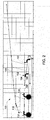
- FIG. 3 shows a flow path profile in diffuser 100 shown in FIG. 1 .
- the flow profile for the diffuser 100 of FIG. 1 is strong throughout a large portion of the radial area of the diffuser 100, even along the inner wall 104.
- the diffuser 100 reduces flow separation, thereby improving diffuser performance over a diffuser flow profile exhibiting flow separation, as shown in FIG. 4.
- FIGS. 3 and 4 represent what is characterized as "weak flow” by 150, while what is characterized by healthy, efficient "strong flow” is represented by 160.
- diffuser 100 reduces flow separation within the diffuser 100, particularly during part load performance of the overall system, by energizing the weak flow boundary layer that is typically present along the inner barrel 102.
- the flow manipulating device 134 such as a pump
- weak flow may be taken from a downstream aft location and injected at an upstream location to improvingly modify the flow profile of the diffuser 100. The result is significant improvement in diffuser performance.
Landscapes
- Engineering & Computer Science (AREA)
- Mechanical Engineering (AREA)
- General Engineering & Computer Science (AREA)
- Jet Pumps And Other Pumps (AREA)
- Structures Of Non-Positive Displacement Pumps (AREA)
Abstract
Description
- The subject matter disclosed herein relates to turbines and, in particular, to diffusers for use with gas turbines and steam turbines.
- Typical gas turbines include a diffuser cone, or diffuser, coupled to a last stage bucket of a rotor. The diffuser serves, generally, to increase static pressure of exhaust gas by decreasing the kinetic energy of the exhaust gas. Generally, this may be achieved by increasing the cross-sectional area of the diffuser in the direction of exhaust gas flow.
- Often, gas turbines are not operated at full load, but are designed for efficiency under such a full load. Therefore, part load performance efficiency is sacrificed, based on the full load design. Such inefficiencies are due, at least in part, to flow separation on a diffuser inner barrel, leading to tip strong flow profiles.
- According to one aspect of the invention, a diffuser having fluidic actuation therein includes a diffuser inlet and an inner barrel extending from proximate the diffuser inlet in a direction relatively downstream of the diffuser inlet. The diffuser also includes an actuating opening in the inner barrel proximate the diffuser inlet. The diffuser further includes a suction opening in the inner barrel located downstream of the actuating opening. The diffuser yet further includes a flow manipulator disposed substantially within the inner barrel.
- According to another aspect of the invention, a diffuser for a gas turbine includes a diffuser inlet, a diffuser outlet, and an outer wall extending from proximate the diffuser inlet to proximate the diffuser outlet. The diffuser also includes an inner barrel having at least one actuating opening and at least one suction opening. The diffuser further includes a flow manipulator disposed substantially within the inner barrel.
- According to yet another aspect of the invention, a gas turbine includes a turbine casing that surrounds a portion of the gas turbine. The gas turbine also includes a diffuser coupled to the turbine casing. The diffuser includes a diffuser inlet, an inner barrel having an actuating opening and a suction opening, and a flow manipulator disposed substantially within the inner barrel.
- These and other advantages and features will become more apparent from the following description taken in conjunction with the drawings.
- The subject matter, which is regarded as the invention, is particularly pointed out and distinctly claimed in the claims at the conclusion of the specification. The foregoing and other features and advantages of the invention are apparent from the following detailed description taken in conjunction with the accompanying drawings in which:
-
FIG. 1 is a side, cross-sectional view of a diffuser according to one aspect of the invention; -
FIG. 2 is a partial side, cross sectional view of the diffuser ofFIG. 1 ; -
FIG. 3 illustrates a diffuser flow profile associated with the diffuser illustrated inFIG. 1 ; and -
FIG. 4 illustrates a diffuser flow profile exhibiting tip strong flow. - The detailed description explains embodiments of the invention, together with advantages and features, by way of example with reference to the drawings.
-
FIGS. 1 and2 illustrate one aspect of adiffuser 100 according to one embodiment of the present invention. In operation, exhaust gas from the gas turbine flows through thediffuser 100 in the direction shown by arrow A. In this description, an object is "downstream" of another object or location if it is displaced from it in the direction of arrow A and is "upstream" if it is displaced from it in a direction opposite of arrow A. - The
diffuser 100 includes aninner barrel 102 havinganinner wall 104 that forms aninner chamber 108. Thediffuser 100 also has aninlet 111 located proximate adiffuser entry end 110 and anoutlet 120 located proximate adiffuser exit end 122. Theinlet 111 is capable of being coupled to a turbine, while theoutlet 120 is capable of being coupled to an adjacent object, such as a silencer. Thediffuser 100 also includes anouter wall 106 radially spaced from theinner wall 104 of theinner barrel 102. The area between theinner wall 104 and theouter wall 106 allows fluid or gas to flow downstream therethrough from theinlet 111 to theoutlet 120 of thediffuser 100. - The
diffuser 100 also includes one ormore struts 116 formed between theinner wall 104 and theouter wall 106. Thestrut 116 serves to hold theinner wall 104 and theouter wall 106 in a fixed relationship to one another. The number ofstruts 116 is variable and commonly ranges from about four to about ten. - The
inner wall 104 of theinner barrel 102 extends from thediffuser inlet 111, ordiffuser entry end 110, in a downstream direction toward thediffuser outlet 120, ordiffuser exit end 122. Theinner barrel 102, and hence theinner wall 104, includes afirst end 124 located proximate thediffuser inlet 111 and asecond end 126 located downstream toward thediffuser outlet 120 and takes on numerous longitudinal contours as theinner barrel 102 extends from thefirst end 124 to thesecond end 126. Theinner barrel 102 may slightly curve continuously from thefirst end 124 to thesecond end 126, may curve slightly for only portions between thefirst end 124 and thesecond end 126, may extend in a substantially straight direction, or may comprise segmented portions, where the overall longitudinal direction of theinner barrel 102 comprises any combination of the curvilinear paths described above. Irrespective of the shape of theinner barrel 102, and more particularly theinner wall 104, theinner barrel 102 andinner wall 104 extend toward thediffuser outlet 120, ordiffuser exit 122, and it is conceivable that theinner barrel 102 andinner wall 104 extend completely to thediffuser outlet 120. - The
inner wall 104 of theinner barrel 102 includes one ormore actuator openings 130. Theinner wall 104 of theinner barrel 102 also includes one ormore suction openings 132 that are located downstream of the one ormore actuator openings 130. Both the actuator opening 130 and the suction opening 132 may vary in size and shape and may be modified for the application. - Disposed within the
inner barrel 102 is aflow manipulating device 134 that may take the form of a pump capable of displacing fluid or gas flow that is captured through thesuction opening 132. Typically, weak flow through thediffuser 100 occurs proximate theinner barrel 102, leading to what is characterized as "tip strong" flow, thereby creating system inefficiency. Thesuction opening 132 allows the common weak flow that passes directly over theinner wall 104 to enter theinner barrel 102 and enter anintake port 136 of theflow manipulating device 134 and is subsequently expelled out of adischarge port 138 of theflow manipulating device 134 with sufficient force to exit the actuatingopening 130 in a manner that manipulates the flow profile of thediffuser 100. The manipulation of flow reduces flow separation, thereby increasing diffusion area. The direction of airflow within theinner barrel 102 from a downstream location to an upstream location is illustrated byarrow 140. Although it is envisioned that oneflow manipulating device 134 will be sufficient to displace the flow, it is conceivable that a plurality offlow manipulating devices 134 may be employed within theinner barrel 102 to work in conjunction to provide the aforementioned desired function. - As previously described, there may be a plurality of
actuator openings 130 and/orsuction openings 132, but regardless of the number of each type of opening 130, 132, thesuction opening 132 is located downstream of the actuator opening 130. Theactuator opening 130 is typically located relatively adjacent thediffuser inlet 111 in order to reduce flow separation early on (i.e., substantially upstream) in the diffuser flow process. It is conceivable that the actuator opening 130 is located at an upstream location relative to one of thestruts 116, while the suction opening 132 is located downstream relative to one of thestruts 116. Additionally, in the case ofmultiple actuator openings 130 andsuction openings 132, the spacing of each respective group may vary, but in any event, the group ofactuator openings 130 will typically be located upstream of thedischarge port 138, while the group ofsuction openings 132 will typically be located downstream of theintake port 136. -
FIG. 3 shows a flow path profile indiffuser 100 shown inFIG. 1 . As can be seen, the flow profile for thediffuser 100 ofFIG. 1 is strong throughout a large portion of the radial area of thediffuser 100, even along theinner wall 104. Thediffuser 100 reduces flow separation, thereby improving diffuser performance over a diffuser flow profile exhibiting flow separation, as shown inFIG. 4. FIGS. 3 and 4 represent what is characterized as "weak flow" by 150, while what is characterized by healthy, efficient "strong flow" is represented by 160. - Advantageously, diffuser 100 reduces flow separation within the
diffuser 100, particularly during part load performance of the overall system, by energizing the weak flow boundary layer that is typically present along theinner barrel 102. By providing theflow manipulating device 134, such as a pump, weak flow may be taken from a downstream aft location and injected at an upstream location to improvingly modify the flow profile of thediffuser 100. The result is significant improvement in diffuser performance. - While the invention has been described in detail in connection with only a limited number of embodiments, it should be readily understood that the invention is not limited to such disclosed embodiments. Rather, the invention can be modified to incorporate any number of variations, alterations, substitutions or equivalent arrangements not heretofore described, but which are commensurate with the scope of the invention. Additionally, while various embodiments of the invention have been described, it is to be understood that aspects of the invention may include only some of the described embodiments. Accordingly, the invention is not to be seen as limited by the foregoing description, but is only limited by the scope of the appended claims.
Claims (15)
- A diffuser having fluidic actuation therein, the diffuser comprising:a diffuser inlet (111);an inner barrel (102) extending from proximate the diffuser inlet in a direction (A) relatively downstream of the diffuser inlet;an actuating opening (130) in the inner barrel (102) proximate the diffuser inlet (111);a suction opening (132) in the inner barrel located downstream of the actuating opening (130); anda flow manipulator (134) disposed substantially within the inner barrel.
- The diffuser of claim 1, wherein the diffuser includes a plurality of actuating openings.
- The diffuser of claim 1 or claim 2, wherein the diffuser includes a plurality of suction openings.
- The diffuser of any preceding claim, wherein the flow manipulator is located substantially between the actuating opening and the suction opening.
- The diffuser of claim 4, wherein the flow manipulator is a pump that is configured to have an intake port proximate the suction opening and a discharge port proximate the actuating opening.
- A diffuser for a gas turbine comprising:a diffuser inlet (111);a diffuser outlet (120);an outer wall (106) extending from substantially the diffuser inlet to substantially the diffuser outlet;an inner barrel (102) having at least one actuating opening (130) and at least one suction opening (132); anda flow manipulator (134) disposed substantially within the inner barrel.
- The diffuser of claim 6, wherein the diffuser includes a plurality of actuating openings.
- The diffuser of claim 6 or claim 7, wherein the diffuser includes a plurality of suction openings.
- The diffuser of any one of claims 6 to 8, wherein the flow manipulator is located substantially between the at least one actuating opening and the at least one suction opening.
- The diffuser of any one of claims 6 to 9, wherein the flow manipulator is a pump that is configured to have an intake port proximate the at least one suction opening and a discharge port proximate the at least one actuating opening.
- A gas turbine comprising:a turbine casing that surrounds a portion of the gas turbine; anda diffuser coupled to the turbine casing, the diffuser including:a diffuser inlet (111);an inner barrel (102) having an actuating opening (130) and a suction opening (132); anda flow manipulator (134) disposed substantially within the inner barrel (102).
- The gas turbine of claim 11, wherein the diffuser includes a plurality of actuating openings.
- The gas turbine of claim 11 or claim 12, wherein the diffuser includes a plurality of suction openings.
- The gas turbine of any one of claims 11 to 13, wherein the flow manipulator is located substantially between the actuating opening and the suction opening.
- The gas turbine of any one of claims 11 to 14, wherein the flow manipulator is a pump that is configured to have an intake port proximate the suction opening and a discharge port proximate the actuating opening.
Applications Claiming Priority (1)
| Application Number | Priority Date | Filing Date | Title |
|---|---|---|---|
| US13/348,027 US20130174553A1 (en) | 2012-01-11 | 2012-01-11 | Diffuser having fluidic actuation |
Publications (2)
| Publication Number | Publication Date |
|---|---|
| EP2615262A2 true EP2615262A2 (en) | 2013-07-17 |
| EP2615262A3 EP2615262A3 (en) | 2018-07-04 |
Family
ID=47664120
Family Applications (1)
| Application Number | Title | Priority Date | Filing Date |
|---|---|---|---|
| EP13150250.2A Withdrawn EP2615262A3 (en) | 2012-01-11 | 2013-01-04 | Diffuser having Fluidic Actuation |
Country Status (5)
| Country | Link |
|---|---|
| US (1) | US20130174553A1 (en) |
| EP (1) | EP2615262A3 (en) |
| JP (1) | JP6183946B2 (en) |
| CN (1) | CN103206274B (en) |
| RU (1) | RU2013100411A (en) |
Cited By (1)
| Publication number | Priority date | Publication date | Assignee | Title |
|---|---|---|---|---|
| EP3396121A1 (en) * | 2017-04-28 | 2018-10-31 | Doosan Heavy Industries & Construction Co., Ltd. | Exhaust diffuser of a gas turbine engine having ejection holes and suction holes |
Families Citing this family (1)
| Publication number | Priority date | Publication date | Assignee | Title |
|---|---|---|---|---|
| EP3054086B1 (en) * | 2015-02-05 | 2017-09-13 | General Electric Technology GmbH | Steam turbine diffuser configuration |
Citations (1)
| Publication number | Priority date | Publication date | Assignee | Title |
|---|---|---|---|---|
| EP0343888A2 (en) * | 1988-05-27 | 1989-11-29 | Herman E. Sheets | Method and apparatus for producing fluid pressure and controlling boundary layer |
Family Cites Families (11)
| Publication number | Priority date | Publication date | Assignee | Title |
|---|---|---|---|---|
| US3123285A (en) * | 1964-03-03 | Diffuser with boundary layer control | ||
| US2729974A (en) * | 1952-02-15 | 1956-01-10 | United Aircraft Corp | Transonic flow control with reduced power |
| US3216455A (en) * | 1961-12-05 | 1965-11-09 | Gen Electric | High performance fluidynamic component |
| US4989807A (en) * | 1988-04-07 | 1991-02-05 | Grumman Aerospace Corporation | S-shaped jet engine inlet diffuser |
| US5467591A (en) * | 1993-12-30 | 1995-11-21 | Combustion Engineering, Inc. | Gas turbine combined cycle system |
| US5603605A (en) * | 1996-04-01 | 1997-02-18 | Fonda-Bonardi; G. | Diffuser |
| US6896475B2 (en) * | 2002-11-13 | 2005-05-24 | General Electric Company | Fluidic actuation for improved diffuser performance |
| US8257025B2 (en) * | 2008-04-21 | 2012-09-04 | Siemens Energy, Inc. | Combustion turbine including a diffuser section with cooling fluid passageways and associated methods |
| US8313286B2 (en) * | 2008-07-28 | 2012-11-20 | Siemens Energy, Inc. | Diffuser apparatus in a turbomachine |
| US8647057B2 (en) * | 2009-06-02 | 2014-02-11 | Siemens Energy, Inc. | Turbine exhaust diffuser with a gas jet producing a coanda effect flow control |
| US20110088379A1 (en) * | 2009-10-15 | 2011-04-21 | General Electric Company | Exhaust gas diffuser |
-
2012
- 2012-01-11 US US13/348,027 patent/US20130174553A1/en not_active Abandoned
-
2013
- 2013-01-04 EP EP13150250.2A patent/EP2615262A3/en not_active Withdrawn
- 2013-01-08 JP JP2013000767A patent/JP6183946B2/en not_active Expired - Fee Related
- 2013-01-10 RU RU2013100411/06A patent/RU2013100411A/en not_active Application Discontinuation
- 2013-01-11 CN CN201310010298.XA patent/CN103206274B/en not_active Expired - Fee Related
Patent Citations (1)
| Publication number | Priority date | Publication date | Assignee | Title |
|---|---|---|---|---|
| EP0343888A2 (en) * | 1988-05-27 | 1989-11-29 | Herman E. Sheets | Method and apparatus for producing fluid pressure and controlling boundary layer |
Cited By (2)
| Publication number | Priority date | Publication date | Assignee | Title |
|---|---|---|---|---|
| EP3396121A1 (en) * | 2017-04-28 | 2018-10-31 | Doosan Heavy Industries & Construction Co., Ltd. | Exhaust diffuser of a gas turbine engine having ejection holes and suction holes |
| US10746059B2 (en) | 2017-04-28 | 2020-08-18 | DOOSAN Heavy Industries Construction Co., LTD | Exhaust diffuser having ejection hole and suction hole, and gas turbine having the same |
Also Published As
| Publication number | Publication date |
|---|---|
| JP6183946B2 (en) | 2017-08-23 |
| CN103206274A (en) | 2013-07-17 |
| EP2615262A3 (en) | 2018-07-04 |
| US20130174553A1 (en) | 2013-07-11 |
| RU2013100411A (en) | 2014-07-20 |
| JP2013142401A (en) | 2013-07-22 |
| CN103206274B (en) | 2016-12-07 |
Similar Documents
| Publication | Publication Date | Title |
|---|---|---|
| US10066638B2 (en) | Centrifugal compressor and turbocharger | |
| JP2003214117A (en) | Diffuser for ground or aircraft gas turbine | |
| EP3048251B1 (en) | Turbine bucket for control of wheelspace purge air | |
| JP2013139781A5 (en) | ||
| US8591184B2 (en) | Hub flowpath contour | |
| US8628297B2 (en) | Tip flowpath contour | |
| EP3483395A3 (en) | Inter-turbine ducts with flow control mechanisms | |
| EP3392468B1 (en) | Exhaust diffuser of a gas turbine engine having variable guide vane rings | |
| KR101619753B1 (en) | Axial compressor for fluid-flow machines | |
| CN110325714A (en) | Exhaust chamber of steam turbine and steam turbine | |
| EP2615263A2 (en) | Diffuser for a gas turbine | |
| EP2615262A2 (en) | Diffuser having Fluidic Actuation | |
| US8870532B2 (en) | Exhaust hood diffuser | |
| EP3396121B1 (en) | Exhaust diffuser of a gas turbine engine having ejection holes and suction holes | |
| JP2011099438A (en) | Steampath flow separation reduction system | |
| CN105822354A (en) | Turbine bucket for control of wheelspace purge air | |
| KR20170029525A (en) | Discharge region of a turbocharger turbine | |
| JP6594019B2 (en) | Inlet guide vane and centrifugal compressor | |
| EP2674572A2 (en) | Turbine exhaust diffuser | |
| CN106662119A (en) | Improved scroll for a turbomachine, turbomachine comprising said scroll, and method of operation | |
| US9388710B2 (en) | Exhaust diffuser arrangement for a turbine system and method of redirecting a flow | |
| EP2873830A1 (en) | Turbocharger, turbine nozzle, and ship | |
| US10570743B2 (en) | Turbomachine having an annulus enlargment and airfoil | |
| JP2007138816A (en) | Method and device for bleeding multiple stage centrifugal compressor | |
| JP2015055229A (en) | Exhaust system for use in turbine and assembly method thereof |
Legal Events
| Date | Code | Title | Description |
|---|---|---|---|
| PUAI | Public reference made under article 153(3) epc to a published international application that has entered the european phase |
Free format text: ORIGINAL CODE: 0009012 |
|
| AK | Designated contracting states |
Kind code of ref document: A2 Designated state(s): AL AT BE BG CH CY CZ DE DK EE ES FI FR GB GR HR HU IE IS IT LI LT LU LV MC MK MT NL NO PL PT RO RS SE SI SK SM TR |
|
| AX | Request for extension of the european patent |
Extension state: BA ME |
|
| PUAL | Search report despatched |
Free format text: ORIGINAL CODE: 0009013 |
|
| AK | Designated contracting states |
Kind code of ref document: A3 Designated state(s): AL AT BE BG CH CY CZ DE DK EE ES FI FR GB GR HR HU IE IS IT LI LT LU LV MC MK MT NL NO PL PT RO RS SE SI SK SM TR |
|
| AX | Request for extension of the european patent |
Extension state: BA ME |
|
| RIC1 | Information provided on ipc code assigned before grant |
Ipc: F01D 25/30 20060101AFI20180529BHEP |
|
| STAA | Information on the status of an ep patent application or granted ep patent |
Free format text: STATUS: REQUEST FOR EXAMINATION WAS MADE |
|
| 17P | Request for examination filed |
Effective date: 20190104 |
|
| RBV | Designated contracting states (corrected) |
Designated state(s): AL AT BE BG CH CY CZ DE DK EE ES FI FR GB GR HR HU IE IS IT LI LT LU LV MC MK MT NL NO PL PT RO RS SE SI SK SM TR |
|
| STAA | Information on the status of an ep patent application or granted ep patent |
Free format text: STATUS: EXAMINATION IS IN PROGRESS |
|
| 17Q | First examination report despatched |
Effective date: 20190228 |
|
| GRAP | Despatch of communication of intention to grant a patent |
Free format text: ORIGINAL CODE: EPIDOSNIGR1 |
|
| STAA | Information on the status of an ep patent application or granted ep patent |
Free format text: STATUS: GRANT OF PATENT IS INTENDED |
|
| INTG | Intention to grant announced |
Effective date: 20201015 |
|
| RIN1 | Information on inventor provided before grant (corrected) |
Inventor name: NANDA, DEEPESH DINESH |
|
| STAA | Information on the status of an ep patent application or granted ep patent |
Free format text: STATUS: THE APPLICATION IS DEEMED TO BE WITHDRAWN |
|
| 18D | Application deemed to be withdrawn |
Effective date: 20210226 |