EP2615248A2 - Fiber composite assembly and process of fabricating a fiber composite assembly - Google Patents
Fiber composite assembly and process of fabricating a fiber composite assembly Download PDFInfo
- Publication number
- EP2615248A2 EP2615248A2 EP20120191895 EP12191895A EP2615248A2 EP 2615248 A2 EP2615248 A2 EP 2615248A2 EP 20120191895 EP20120191895 EP 20120191895 EP 12191895 A EP12191895 A EP 12191895A EP 2615248 A2 EP2615248 A2 EP 2615248A2
- Authority
- EP
- European Patent Office
- Prior art keywords
- fiber
- composite
- composite layer
- helical
- helix
- Prior art date
- Legal status (The legal status is an assumption and is not a legal conclusion. Google has not performed a legal analysis and makes no representation as to the accuracy of the status listed.)
- Withdrawn
Links
Images
Classifications
-
- B—PERFORMING OPERATIONS; TRANSPORTING
- B29—WORKING OF PLASTICS; WORKING OF SUBSTANCES IN A PLASTIC STATE IN GENERAL
- B29C—SHAPING OR JOINING OF PLASTICS; SHAPING OF MATERIAL IN A PLASTIC STATE, NOT OTHERWISE PROVIDED FOR; AFTER-TREATMENT OF THE SHAPED PRODUCTS, e.g. REPAIRING
- B29C70/00—Shaping composites, i.e. plastics material comprising reinforcements, fillers or preformed parts, e.g. inserts
- B29C70/04—Shaping composites, i.e. plastics material comprising reinforcements, fillers or preformed parts, e.g. inserts comprising reinforcements only, e.g. self-reinforcing plastics
- B29C70/06—Fibrous reinforcements only
- B29C70/10—Fibrous reinforcements only characterised by the structure of fibrous reinforcements, e.g. hollow fibres
- B29C70/16—Fibrous reinforcements only characterised by the structure of fibrous reinforcements, e.g. hollow fibres using fibres of substantial or continuous length
- B29C70/22—Fibrous reinforcements only characterised by the structure of fibrous reinforcements, e.g. hollow fibres using fibres of substantial or continuous length oriented in at least two directions forming a two-dimensional [2D] structure
-
- B—PERFORMING OPERATIONS; TRANSPORTING
- B29—WORKING OF PLASTICS; WORKING OF SUBSTANCES IN A PLASTIC STATE IN GENERAL
- B29C—SHAPING OR JOINING OF PLASTICS; SHAPING OF MATERIAL IN A PLASTIC STATE, NOT OTHERWISE PROVIDED FOR; AFTER-TREATMENT OF THE SHAPED PRODUCTS, e.g. REPAIRING
- B29C70/00—Shaping composites, i.e. plastics material comprising reinforcements, fillers or preformed parts, e.g. inserts
- B29C70/04—Shaping composites, i.e. plastics material comprising reinforcements, fillers or preformed parts, e.g. inserts comprising reinforcements only, e.g. self-reinforcing plastics
- B29C70/06—Fibrous reinforcements only
- B29C70/10—Fibrous reinforcements only characterised by the structure of fibrous reinforcements, e.g. hollow fibres
- B29C70/16—Fibrous reinforcements only characterised by the structure of fibrous reinforcements, e.g. hollow fibres using fibres of substantial or continuous length
- B29C70/24—Fibrous reinforcements only characterised by the structure of fibrous reinforcements, e.g. hollow fibres using fibres of substantial or continuous length oriented in at least three directions forming a three-dimensional [3D] structure
-
- F—MECHANICAL ENGINEERING; LIGHTING; HEATING; WEAPONS; BLASTING
- F01—MACHINES OR ENGINES IN GENERAL; ENGINE PLANTS IN GENERAL; STEAM ENGINES
- F01D—NON-POSITIVE DISPLACEMENT MACHINES OR ENGINES, e.g. STEAM TURBINES
- F01D5/00—Blades; Blade-carrying members; Heating, heat-insulating, cooling or antivibration means on the blades or the members
- F01D5/12—Blades
- F01D5/28—Selecting particular materials; Particular measures relating thereto; Measures against erosion or corrosion
- F01D5/282—Selecting composite materials, e.g. blades with reinforcing filaments
-
- B—PERFORMING OPERATIONS; TRANSPORTING
- B29—WORKING OF PLASTICS; WORKING OF SUBSTANCES IN A PLASTIC STATE IN GENERAL
- B29C—SHAPING OR JOINING OF PLASTICS; SHAPING OF MATERIAL IN A PLASTIC STATE, NOT OTHERWISE PROVIDED FOR; AFTER-TREATMENT OF THE SHAPED PRODUCTS, e.g. REPAIRING
- B29C53/00—Shaping by bending, folding, twisting, straightening or flattening; Apparatus therefor
- B29C53/02—Bending or folding
- B29C53/12—Bending or folding helically, e.g. for making springs
-
- B—PERFORMING OPERATIONS; TRANSPORTING
- B29—WORKING OF PLASTICS; WORKING OF SUBSTANCES IN A PLASTIC STATE IN GENERAL
- B29K—INDEXING SCHEME ASSOCIATED WITH SUBCLASSES B29B, B29C OR B29D, RELATING TO MOULDING MATERIALS OR TO MATERIALS FOR MOULDS, REINFORCEMENTS, FILLERS OR PREFORMED PARTS, e.g. INSERTS
- B29K2105/00—Condition, form or state of moulded material or of the material to be shaped
- B29K2105/06—Condition, form or state of moulded material or of the material to be shaped containing reinforcements, fillers or inserts
- B29K2105/08—Condition, form or state of moulded material or of the material to be shaped containing reinforcements, fillers or inserts of continuous length, e.g. cords, rovings, mats, fabrics, strands or yarns
- B29K2105/10—Cords, strands or rovings, e.g. oriented cords, strands or rovings
- B29K2105/101—Oriented
- B29K2105/103—Oriented helically
-
- B—PERFORMING OPERATIONS; TRANSPORTING
- B29—WORKING OF PLASTICS; WORKING OF SUBSTANCES IN A PLASTIC STATE IN GENERAL
- B29L—INDEXING SCHEME ASSOCIATED WITH SUBCLASS B29C, RELATING TO PARTICULAR ARTICLES
- B29L2031/00—Other particular articles
- B29L2031/774—Springs
- B29L2031/7742—Springs helical springs
-
- F—MECHANICAL ENGINEERING; LIGHTING; HEATING; WEAPONS; BLASTING
- F05—INDEXING SCHEMES RELATING TO ENGINES OR PUMPS IN VARIOUS SUBCLASSES OF CLASSES F01-F04
- F05D—INDEXING SCHEME FOR ASPECTS RELATING TO NON-POSITIVE-DISPLACEMENT MACHINES OR ENGINES, GAS-TURBINES OR JET-PROPULSION PLANTS
- F05D2250/00—Geometry
- F05D2250/20—Three-dimensional
- F05D2250/25—Three-dimensional helical
-
- Y—GENERAL TAGGING OF NEW TECHNOLOGICAL DEVELOPMENTS; GENERAL TAGGING OF CROSS-SECTIONAL TECHNOLOGIES SPANNING OVER SEVERAL SECTIONS OF THE IPC; TECHNICAL SUBJECTS COVERED BY FORMER USPC CROSS-REFERENCE ART COLLECTIONS [XRACs] AND DIGESTS
- Y10—TECHNICAL SUBJECTS COVERED BY FORMER USPC
- Y10T—TECHNICAL SUBJECTS COVERED BY FORMER US CLASSIFICATION
- Y10T428/00—Stock material or miscellaneous articles
- Y10T428/249921—Web or sheet containing structurally defined element or component
- Y10T428/249922—Embodying intertwined or helical component[s]
Definitions
- the present invention is directed to manufacturing processes and manufactured products. More specifically, the present invention is directed to fiber composite assemblies and processes of fabricating fiber composite assemblies.
- Composite assemblies are consistently being subjected to more difficult environments. For example, composite assemblies form products that are subjected to large temperature ranges, high stress, and other physical challenges. As such, there is a constant need to augment the physical properties of such composite assemblies to permit use in a greater range of environments.
- Composite assemblies made from laminate ply stacks have structural weaknesses in interlaminar and in-plane fiber directions. The shear loading in these directions is highly dependent on a matrix's strength that is used for forming the composite assembly.
- a known composite flywheel rim includes a spiraled composite assembly having fibers incorporated therein. The fibers are arranged in a lattice forming the spiraled composite but are not spiraled themselves and, thus, do not include the physical properties provided by spiraled fibers.
- Another known composite includes fiber reinforced composite resin.
- the resin includes multiple plies, each having a plurality of elongate fibers.
- the elongate fibers are not spiraled fibers and, thus, do not include the physical properties provided by spiraled fibers.
- Spiraled fibers include a planar geometric arrangement of the fiber swirling into a central portion.
- Known spiraled fiber systems also suffer from drawbacks.
- Known spiraled fiber systems can require use of large amounts of fibrous materials to form a spiraled multilayer fiber.
- a fiber composite assembly and a process of fabricating a fiber composite assembly that do not suffer from the above drawbacks would be desirable in the art.
- a process of fabricating a fiber composite assembly includes providing a wound fiber preform and elongating the wound fiber preform to form a helical fiber.
- a process of fabricating a fiber composite assembly includes positioning a first fiber in a first composite layer and positioning a second fiber in a second composite layer.
- the first fiber includes a helical portion and the second fiber extends to within the helical portion of the first fiber.
- a fiber composite assembly in another exemplary embodiment, includes a first composite layer having a first fiber and a second composite layer having a second layer.
- the first fiber includes a helical portion and the second fiber extends to within the helical portion of the first fiber.
- Embodiments of the present disclosure permit use of fiber composite assemblies in a greater range of environments than other known assemblies, in harsher (hotter, colder, higher stress, or combinations thereof) environments than other known assemblies, permit increased structural integrity (for example, where known assemblies have weaknesses, such as, in interlaminar and in-plane fiber directions), decrease dependence on matrix properties in providing desired properties for fiber composite assemblies, permit formation of fibers having properties and/or compositions not previously available, and combinations thereof.
- FIG. 1 shows a process 100 according to the disclosure.
- the process 100 includes providing a fiber preform 102 (step 101) that is formed by any suitable process.
- the fiber preform 102 is a wound fiber preform having a helical geometry.
- the fiber preform 100 is positioned on an elongate member 104.
- the elongate member 104 includes a geometry corresponding to the fiber preform 102, for example, cylindrical, oval cylindrical, square, rectangular, triangular, pentagonal, hexagonal, heptagonal, octagonal, or any other suitable simple or complex geometry.
- the fiber preform 102 is elongated (step 103).
- step 103 By elongating the fiber preform 102 (step 103), open regions 106 are formed between fiber regions 108 (such as helical portions).
- the elongating (step 103) is achieved by providing a force, such as by pulling a portion or the end of the fiber preform 102 in one or both directions along the elongate member 104.
- the fiber preform 102 is coated with a curing agent to temporarily fix the fiber in a helical orientation and to provide support of the fiber preform 102 during subsequent alignment and/or positioning.
- the fiber preform 102 Upon being elongated (step 103) to a predetermined distance, the fiber preform 102 is transformed and a helical fiber 110 is formed (step 105).
- the helical fiber 110 is or includes a circular-helix geometry.
- the helical fiber 110 is or includes a square helix geometry (see FIG. 2 ), a triangular-helix geometry (see FIG. 3 ), a pentagonal-helix geometry (see FIG. 4 ), a hexagonal-helix geometry (see FIG. 5 ), a heptagonal-helix geometry (see FIG. 6 ), an octagonal-helix geometry (see FIG.
- the helical fiber 110 is a double-helix formed, for example, by winding a first helical fiber 110 into a second helical fiber 110.
- the helical fiber 110 includes a simple geometry, for example, a pure circular-helix geometry and/or a geometry having substantially equal sides 202 (see FIG. 2 ), such as, a pure square-helix geometry, a pure triangular-helix geometry, a pure pentagonal-helix geometry, a pure hexagonal-helix geometry, a pure heptagonal-helix geometry, a pure octagonal-helix geometry, any other suitable pure geometry, or any suitable combination thereof.
- the helical fiber 110 includes one or more sides or portions that are not equal and, thus, a complex geometry.
- the helical fiber 110 spirals inward, for example, when formed with the elongate member 104 having a wider portion at one end and a narrower portion at the other end).
- the material of the helical fiber 110 is any suitable material.
- the helical fiber 110 is a braided fiber including one or more portions that are braided.
- the helical fiber 110 is a monofiber, for example, a fiber having a single material and/or single layer of the single material.
- the helical fiber 110 is a multilayered fiber, for example, having multiple layers of the same material or layers of differing materials.
- the helical fiber 110 includes silicon carbide monofilaments, ceramic fibers, carbon fibers, polypropylene filaments, or a combination thereof.
- FIG. 8 shows an embodiment of a process 800 according to the disclosure.
- the process 800 shown in FIG. 8 is separate from the process 100 shown in FIG. 1 or a continuation of the process shown in FIG. 1 .
- the process 800 shown in FIG. 8 includes positioning one or more of the helical fibers 110 in a matrix 802 (step 801).
- the matrix 802 is selected from the group consisting of ceramic materials, organic materials, metals, and metallic alloys.
- the matrix 802 and the helical fiber(s) 110 are arranged as a composite layer 804.
- the helical fibers 110 permit interlacing in vertical and/or horizontal directions.
- Arranging the helical fibers 110 in an interlaced orientation within the composite layer 804 provides a load path that is capable of carrying inter-laminar loading between the composite layer 804 and additional layers.
- the positioning of the helical fibers 110 increases interlaminar tensile strength and interlaminar shear strength and/or provides a greater amount of interlaminar tensile strength and interlaminar shear strength than a non-helical fiber (not shown) would provide.
- the process 800 continues with a plurality of the composite layer 804 being positioned (step 803).
- a first composite layer 804a is positioned on a second composite layer 804b.
- additional composite layers 804 for example, a third composite layer 804c and a fourth composite layer 804d are similarly positioned.
- Any suitable number of composite layers 804 are positioned according to the process 800. Suitable amounts of the composite layers 804 include, but are not limited to, two of the composite layers 804, three of the composite layers 804, four of the composite layers 804, five of the composite layers 804, six of the composite layers 804, ten of the composite layers 804, fifteen of the composite layers 804, or more.
- the positioned composite layers 804 include the fiber regions 108 of one or more of the helical fibers 110 in one of the composite layers 804 extending into open regions 106 of one or more of the helical fibers 110 in another of the composite layers 804.
- a fiber composite assembly 806 is formed (step 805).
- the forming (step 805) of the fiber composite assembly 806 includes heating, pressing, and/or otherwise curing the matrix 802 of one or more of the composite layers 804.
- the forming (step 805) of the matrix 802 into the fiber composite assembly 806 is partially accomplished prior to the positioning of the composite layer 804 (step 803), completely accomplished prior to the positioning of the composite layer 804 (step 803), partially accomplished during the positioning of the composite layer (step 803), completely accomplished during the positioning of the composite layer (step 803), partially accomplished after the positioning of the composite layer (step 803), completely accomplished after the positioning of the composite layer (step 803), or a combination thereof.
- the positioning of the composite layers 804 includes orienting each of the composite layers 804 such that the helical fibers 110 in each of the composite layers 804 are oriented in the same direction.
- the fiber composite assembly 806 formed from the composite layers 804 has increased interlayer adhesion attributable to the helical fibers 110.
- the fiber composite assembly 806 includes some flexibility in comparison to having the helical fibers 110 arranged in more than one direction.
- the positioning of the composite layers 804 includes orienting one or more of the composite layers 804 such that the helical fibers 110 are oriented at a plurality of directions, for example, the helical fibers 110 in a first composite layer 804e being perpendicular or generally perpendicular to the helical fibers 110 in a second composite layer 804f.
- the fiber composite assembly 806 formed from the composite layers 804 has increased interlayer adhesion attributable to the helical fibers 110 and is more rigid than the fiber composite assembly 806 formed with the helical fibers 110 in each of the composite layers 804 being oriented in the same direction.
- the orienting of the composite layers 804 in the embodiments shown in FIGS. 8 and 9 can be used for forming the fiber composite assembly 806 with increased interlaminar properties.
- unidirectional loading of a desired use for the composite assembly 806 is in-line or substantially in-line with the orientation of the helical fiber 110.
- Such uses include the fiber composite assembly 806 forming a portion or all of a gas turbine airfoil, a marine or aviation based composite structural body, athletic equipment, or other suitable applications benefiting from the advantages described herein.
- tangential loadings, or secondary loadings of a desired use for the composite assembly 806 are in-line or substantially in-line with portions of the helical fiber 110 (such as the helical portions of the fiber region 108), thereby distributing a portion of such loads between composite layers 804.
Landscapes
- Engineering & Computer Science (AREA)
- Chemical & Material Sciences (AREA)
- Textile Engineering (AREA)
- Composite Materials (AREA)
- Mechanical Engineering (AREA)
- Materials Engineering (AREA)
- General Engineering & Computer Science (AREA)
- Woven Fabrics (AREA)
- Reinforced Plastic Materials (AREA)
- Nonwoven Fabrics (AREA)
- Yarns And Mechanical Finishing Of Yarns Or Ropes (AREA)
Abstract
A fiber composite assembly (806) and a process of fabricating a fiber composite assembly (806) are disclosed. The fiber composite assembly (806) includes a first composite layer (804a) having a first fiber (110) and a second composite layer (804b) having a second layer. The first fiber (110) includes a helical portion (106) and the second fiber extends to within the helical portion (106) of the first fiber. A process of fabricating a fiber composite assembly includes elongating a wound fiber preform to form a helical fiber or positioning the first fiber in the first composite layer and positioning the second fiber in the second composite layer.
Description
- The present invention is directed to manufacturing processes and manufactured products. More specifically, the present invention is directed to fiber composite assemblies and processes of fabricating fiber composite assemblies.
- Composite assemblies are consistently being subjected to more difficult environments. For example, composite assemblies form products that are subjected to large temperature ranges, high stress, and other physical challenges. As such, there is a constant need to augment the physical properties of such composite assemblies to permit use in a greater range of environments.
- Specifically, it is desirable to improve load carrying capacity for composite assemblies. Composite assemblies made from laminate ply stacks have structural weaknesses in interlaminar and in-plane fiber directions. The shear loading in these directions is highly dependent on a matrix's strength that is used for forming the composite assembly.
- Use of specific matrix materials permits some improvement in composite assemblies. However, such matrix materials can be expensive, can be unavailable, and/or can be incompatible with certain environments. Additionally or alternatively, specific fibers or fibers in conjunction with other materials, such as wires, can also be used. For example, a known composite flywheel rim includes a spiraled composite assembly having fibers incorporated therein. The fibers are arranged in a lattice forming the spiraled composite but are not spiraled themselves and, thus, do not include the physical properties provided by spiraled fibers.
- Another known composite includes fiber reinforced composite resin. The resin includes multiple plies, each having a plurality of elongate fibers. However, the elongate fibers are not spiraled fibers and, thus, do not include the physical properties provided by spiraled fibers. Spiraled fibers include a planar geometric arrangement of the fiber swirling into a central portion. Known spiraled fiber systems also suffer from drawbacks. Known spiraled fiber systems can require use of large amounts of fibrous materials to form a spiraled multilayer fiber.
- A fiber composite assembly and a process of fabricating a fiber composite assembly that do not suffer from the above drawbacks would be desirable in the art.
- In an exemplary embodiment, a process of fabricating a fiber composite assembly includes providing a wound fiber preform and elongating the wound fiber preform to form a helical fiber.
- In another exemplary embodiment, a process of fabricating a fiber composite assembly includes positioning a first fiber in a first composite layer and positioning a second fiber in a second composite layer. The first fiber includes a helical portion and the second fiber extends to within the helical portion of the first fiber.
- In another exemplary embodiment, a fiber composite assembly includes a first composite layer having a first fiber and a second composite layer having a second layer. The first fiber includes a helical portion and the second fiber extends to within the helical portion of the first fiber.
- Other features and advantages of the present invention will be apparent from the following more detailed description of the preferred embodiment, taken in conjunction with the accompanying drawings which illustrate, by way of example, the principles of the invention.
-
-
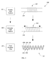
FIG. 1 shows a schematic view of a process of forming an elongate helical fiber according to an embodiment of the disclosure. -
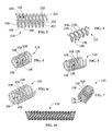
FIG. 2 shows a perspective view of a helical fiber having a square-helix geometry according to the disclosure. -
FIG. 3 shows a perspective view of a helical fiber having a triangular-helix geometry according to the disclosure. -
FIG. 4 shows a perspective view of a helical fiber having a pentagonal-helix geometry according to the disclosure. -
FIG. 5 shows a perspective view of a helical fiber having a hexagonal-helix geometry according to the disclosure. -
FIG. 6 shows a perspective view of a helical fiber having a heptagonal-helix geometry according to the disclosure. -
FIG. 7 shows a perspective view of a helical fiber having an octagonal-helix geometry according to the disclosure. -
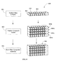
FIG. 8 shows a schematic view of an exemplary process of forming a fiber composite assembly according to the disclosure. -
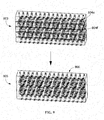
FIG. 9 shows a schematic view of an exemplary process of forming a fiber composite assembly according to the disclosure. -
FIG. 10 shows a perspective view of a helical fiber according to the disclosure. - Wherever possible, the same reference numbers will be used throughout the drawings to represent the same parts.
- Provided is a fiber composite assembly and a process of fabricating a fiber composite assembly. Embodiments of the present disclosure permit use of fiber composite assemblies in a greater range of environments than other known assemblies, in harsher (hotter, colder, higher stress, or combinations thereof) environments than other known assemblies, permit increased structural integrity (for example, where known assemblies have weaknesses, such as, in interlaminar and in-plane fiber directions), decrease dependence on matrix properties in providing desired properties for fiber composite assemblies, permit formation of fibers having properties and/or compositions not previously available, and combinations thereof.
-
FIG. 1 shows aprocess 100 according to the disclosure. Theprocess 100 includes providing a fiber preform 102 (step 101) that is formed by any suitable process. Thefiber preform 102 is a wound fiber preform having a helical geometry. In one embodiment, thefiber preform 100 is positioned on anelongate member 104. Theelongate member 104 includes a geometry corresponding to thefiber preform 102, for example, cylindrical, oval cylindrical, square, rectangular, triangular, pentagonal, hexagonal, heptagonal, octagonal, or any other suitable simple or complex geometry. - In the
process 100, thefiber preform 102 is elongated (step 103). By elongating the fiber preform 102 (step 103),open regions 106 are formed between fiber regions 108 (such as helical portions). In one embodiment, the elongating (step 103) is achieved by providing a force, such as by pulling a portion or the end of the fiber preform 102 in one or both directions along theelongate member 104. In one embodiment, thefiber preform 102 is coated with a curing agent to temporarily fix the fiber in a helical orientation and to provide support of thefiber preform 102 during subsequent alignment and/or positioning. Upon being elongated (step 103) to a predetermined distance, thefiber preform 102 is transformed and ahelical fiber 110 is formed (step 105). As shown inFIG. 1 , in one embodiment, thehelical fiber 110 is or includes a circular-helix geometry. In other embodiments, thehelical fiber 110 is or includes a square helix geometry (seeFIG. 2 ), a triangular-helix geometry (seeFIG. 3 ), a pentagonal-helix geometry (seeFIG. 4 ), a hexagonal-helix geometry (seeFIG. 5 ), a heptagonal-helix geometry (seeFIG. 6 ), an octagonal-helix geometry (seeFIG. 7 ), any other suitable geometry, or any suitable combinations thereof (for example, when formed with theelongate member 104 having portions with different geometries corresponding to more than one of the geometries). As shown inFIG. 10 , in one embodiment, thehelical fiber 110 is a double-helix formed, for example, by winding a firsthelical fiber 110 into a secondhelical fiber 110. - In one embodiment, the
helical fiber 110 includes a simple geometry, for example, a pure circular-helix geometry and/or a geometry having substantially equal sides 202 (seeFIG. 2 ), such as, a pure square-helix geometry, a pure triangular-helix geometry, a pure pentagonal-helix geometry, a pure hexagonal-helix geometry, a pure heptagonal-helix geometry, a pure octagonal-helix geometry, any other suitable pure geometry, or any suitable combination thereof. Additionally or alternatively, on one embodiment, thehelical fiber 110 includes one or more sides or portions that are not equal and, thus, a complex geometry. In a further embodiment, thehelical fiber 110 spirals inward, for example, when formed with theelongate member 104 having a wider portion at one end and a narrower portion at the other end). - The material of the
helical fiber 110 is any suitable material. In one embodiment, thehelical fiber 110 is a braided fiber including one or more portions that are braided. In one embodiment, thehelical fiber 110 is a monofiber, for example, a fiber having a single material and/or single layer of the single material. In one embodiment, thehelical fiber 110 is a multilayered fiber, for example, having multiple layers of the same material or layers of differing materials. In one embodiment, thehelical fiber 110 includes silicon carbide monofilaments, ceramic fibers, carbon fibers, polypropylene filaments, or a combination thereof. -
FIG. 8 shows an embodiment of aprocess 800 according to the disclosure. Theprocess 800 shown inFIG. 8 is separate from theprocess 100 shown inFIG. 1 or a continuation of the process shown inFIG. 1 . Theprocess 800 shown inFIG. 8 includes positioning one or more of thehelical fibers 110 in a matrix 802 (step 801). In one embodiment, thematrix 802 is selected from the group consisting of ceramic materials, organic materials, metals, and metallic alloys. Thematrix 802 and the helical fiber(s) 110 are arranged as acomposite layer 804. In one embodiment, thehelical fibers 110 permit interlacing in vertical and/or horizontal directions. Arranging thehelical fibers 110 in an interlaced orientation within thecomposite layer 804 provides a load path that is capable of carrying inter-laminar loading between thecomposite layer 804 and additional layers. In one embodiment, the positioning of thehelical fibers 110 increases interlaminar tensile strength and interlaminar shear strength and/or provides a greater amount of interlaminar tensile strength and interlaminar shear strength than a non-helical fiber (not shown) would provide. - The
process 800 continues with a plurality of thecomposite layer 804 being positioned (step 803). For example, in one embodiment, a firstcomposite layer 804a is positioned on a secondcomposite layer 804b. In further embodiments, additionalcomposite layers 804, for example, a thirdcomposite layer 804c and a fourthcomposite layer 804d are similarly positioned. Any suitable number ofcomposite layers 804 are positioned according to theprocess 800. Suitable amounts of thecomposite layers 804 include, but are not limited to, two of thecomposite layers 804, three of thecomposite layers 804, four of thecomposite layers 804, five of thecomposite layers 804, six of thecomposite layers 804, ten of thecomposite layers 804, fifteen of thecomposite layers 804, or more. In one embodiment, the positionedcomposite layers 804 include thefiber regions 108 of one or more of thehelical fibers 110 in one of thecomposite layers 804 extending intoopen regions 106 of one or more of thehelical fibers 110 in another of the composite layers 804. - After two or more of the
composite layers 804 are positioned, a fibercomposite assembly 806 is formed (step 805). In one embodiment, the forming (step 805) of the fibercomposite assembly 806 includes heating, pressing, and/or otherwise curing thematrix 802 of one or more of the composite layers 804. The forming (step 805) of thematrix 802 into the fibercomposite assembly 806 is partially accomplished prior to the positioning of the composite layer 804 (step 803), completely accomplished prior to the positioning of the composite layer 804 (step 803), partially accomplished during the positioning of the composite layer (step 803), completely accomplished during the positioning of the composite layer (step 803), partially accomplished after the positioning of the composite layer (step 803), completely accomplished after the positioning of the composite layer (step 803), or a combination thereof. - As shown in
FIG. 8 , in one embodiment, the positioning of the composite layers 804 (step 803) includes orienting each of thecomposite layers 804 such that thehelical fibers 110 in each of thecomposite layers 804 are oriented in the same direction. In this embodiment, the fibercomposite assembly 806 formed from thecomposite layers 804 has increased interlayer adhesion attributable to thehelical fibers 110. In addition, the fibercomposite assembly 806 includes some flexibility in comparison to having thehelical fibers 110 arranged in more than one direction. - As shown in
FIG. 9 , in one embodiment, the positioning of the composite layers 804 (step 803) includes orienting one or more of thecomposite layers 804 such that thehelical fibers 110 are oriented at a plurality of directions, for example, thehelical fibers 110 in a firstcomposite layer 804e being perpendicular or generally perpendicular to thehelical fibers 110 in a secondcomposite layer 804f. In this embodiment, the fibercomposite assembly 806 formed from thecomposite layers 804 has increased interlayer adhesion attributable to thehelical fibers 110 and is more rigid than the fibercomposite assembly 806 formed with thehelical fibers 110 in each of thecomposite layers 804 being oriented in the same direction. - For example, the orienting of the
composite layers 804 in the embodiments shown inFIGS. 8 and9 can be used for forming the fibercomposite assembly 806 with increased interlaminar properties. In one embodiment, unidirectional loading of a desired use for thecomposite assembly 806 is in-line or substantially in-line with the orientation of thehelical fiber 110. Such uses include the fibercomposite assembly 806 forming a portion or all of a gas turbine airfoil, a marine or aviation based composite structural body, athletic equipment, or other suitable applications benefiting from the advantages described herein. Additionally or alternatively, in one embodiment, tangential loadings, or secondary loadings of a desired use for thecomposite assembly 806 are in-line or substantially in-line with portions of the helical fiber 110 (such as the helical portions of the fiber region 108), thereby distributing a portion of such loads betweencomposite layers 804. - While the invention has been described with reference to a preferred embodiment, it will be understood by those skilled in the art that various changes may be made and equivalents may be substituted for elements thereof without departing from the scope of the invention. In addition, many modifications may be made to adapt a particular situation or material to the teachings of the invention without departing from the essential scope thereof. Therefore, it is intended that the invention not be limited to the particular embodiment disclosed as the best mode contemplated for carrying out this invention, but that the invention will include all embodiments falling within the scope of the appended claims.
Claims (14)
- A process of fabricating a fiber composite assembly, the process comprising:positioning a first fiber in a first composite layer; andpositioning a second fiber in a second composite layer;wherein the first fiber includes a helical portion and the second fiber extends to within the helical portion of the first fiber.
- The process of claim 1, further comprising elongating a wound fiber preform to form the first fiber.
- The process of claim 1 or claim 2, wherein the first composite layer is a ceramic composite layer, an organic composite layer or a metal composite layer.
- The process of any preceding claim, wherein the second fiber is helical.
- The process of any preceding claim, wherein the first fiber is a square-helix, a round-helix, or a complex helix selected from the group consisting of an oval-helix, a triangular-helix, a pentagonal-helix, hexagonal-helix, heptagonal-helix, an octagonal-helix, and combinations thereof.
- The process of any preceding claim, wherein the first fiber is a triangle-helix.
- The process of any preceding claim, wherein the first fiber is a braided fiber, a mono-fiber or a multilayered fiber.
- The process of any preceding claim, wherein the first fiber is a silicon carbide monofilament, ceramic fiber, carbon fiber, or a polypropylene filament.
- A fiber composite assembly, comprising:a first composite layer having a first fiber; anda second composite layer having a second layer;wherein the first fiber includes a helical portion and the second fiber extends to within the helical portion of the first fiber.
- The assembly of claim 9, wherein the first composite layer is a ceramic composite layer.
- The assembly of claim 9, wherein the first composite layer is an organic composite layer.
- The assembly of claim 9, wherein the first composite layer is a metal composite layer.
- The assembly of claim 9, wherein the first fiber is a silicon carbide monofilament, ceramic fiber, carbon fiber, or a polypropylene filament.
- A process of fabricating a fiber composite assembly, the process comprising:providing a wound fiber preform; andelongating the wound fiber preform to form a helical fiber.
Applications Claiming Priority (1)
| Application Number | Priority Date | Filing Date | Title |
|---|---|---|---|
| US13/348,741 US20130183514A1 (en) | 2012-01-12 | 2012-01-12 | Fiber composite assembly and process of fabricating a fiber composite assembly |
Publications (1)
| Publication Number | Publication Date |
|---|---|
| EP2615248A2 true EP2615248A2 (en) | 2013-07-17 |
Family
ID=47172502
Family Applications (1)
| Application Number | Title | Priority Date | Filing Date |
|---|---|---|---|
| EP20120191895 Withdrawn EP2615248A2 (en) | 2012-01-12 | 2012-11-08 | Fiber composite assembly and process of fabricating a fiber composite assembly |
Country Status (5)
| Country | Link |
|---|---|
| US (1) | US20130183514A1 (en) |
| EP (1) | EP2615248A2 (en) |
| JP (1) | JP2013142217A (en) |
| CN (1) | CN103203905A (en) |
| RU (1) | RU2012147545A (en) |
Families Citing this family (6)
| Publication number | Priority date | Publication date | Assignee | Title |
|---|---|---|---|---|
| DE102014207151A1 (en) | 2014-04-14 | 2015-10-15 | Leichtbau-Zentrum Sachsen Gmbh | Torsionally loaded rod-shaped component |
| CN104149400B (en) * | 2014-07-14 | 2016-10-05 | 华南理工大学 | A kind of Double helix fiber enhanced foam laminate |
| RU2592882C1 (en) * | 2015-05-15 | 2016-07-27 | Александр Павлович Белоглазов | Building block |
| CN106747533B (en) * | 2016-06-13 | 2017-12-19 | 北京航空航天大学 | A kind of fiber architecture mode for improving numbers of hot-side engine component ceramic matric composite mechanical property |
| US11998432B2 (en) | 2016-06-30 | 2024-06-04 | Kimberly-Clark Worldwide, Inc. | Method of manufacturing a foam and fiber composite |
| KR102229117B1 (en) * | 2019-11-29 | 2021-03-17 | 한국세라믹기술원 | SiC FINE FIBER HAVING CURL STRUCTURE, MANUFACTURING METHOD THEREOF, COMPLEX YARN USING THE SAME AND MANUFACTURING METHOD THEREOF |
Family Cites Families (2)
| Publication number | Priority date | Publication date | Assignee | Title |
|---|---|---|---|---|
| US5753355A (en) * | 1995-04-20 | 1998-05-19 | Nippon Laser & Electronics Lab. | Collective helical-elements structure |
| US7025914B2 (en) * | 2000-12-22 | 2006-04-11 | Kimberly-Clark Worldwide, Inc. | Multilayer approach to producing homofilament crimp spunbond |
-
2012
- 2012-01-12 US US13/348,741 patent/US20130183514A1/en not_active Abandoned
- 2012-11-02 JP JP2012242286A patent/JP2013142217A/en active Pending
- 2012-11-08 EP EP20120191895 patent/EP2615248A2/en not_active Withdrawn
- 2012-11-09 RU RU2012147545/03A patent/RU2012147545A/en not_active Application Discontinuation
- 2012-11-12 CN CN2012104507675A patent/CN103203905A/en active Pending
Non-Patent Citations (1)
| Title |
|---|
| None |
Also Published As
| Publication number | Publication date |
|---|---|
| JP2013142217A (en) | 2013-07-22 |
| RU2012147545A (en) | 2014-05-20 |
| CN103203905A (en) | 2013-07-17 |
| US20130183514A1 (en) | 2013-07-18 |
Similar Documents
| Publication | Publication Date | Title |
|---|---|---|
| EP2615248A2 (en) | Fiber composite assembly and process of fabricating a fiber composite assembly | |
| US11376812B2 (en) | Shock and impact resistant structures | |
| US12275227B2 (en) | Composite materials and structures | |
| US8293356B2 (en) | Subsurface inclusions of objects for increasing interlaminar shear strength of a ceramic matrix composite structure | |
| US10557267B2 (en) | Truss structure | |
| US20160101591A1 (en) | Composite article | |
| JP7177100B2 (en) | Woven 3D fiber reinforced structure and method of making same | |
| KR102946705B1 (en) | Composite materials and structures | |
| US11059239B2 (en) | Method and apparatus for composite rib and rib-and-sheet molding | |
| EP2743064B1 (en) | Lightning strike protection means and fibre composite component | |
| CN110386242A (en) | Use three dimensional printing thermoplasticity pin toughening composition | |
| US10584491B2 (en) | Truss structure | |
| CA3001294C (en) | Multilayer fabric | |
| CN103459067B (en) | For the method manufacturing the axisymmetric metal parts of monoblock type from complex structure of filament | |
| EP1364772A1 (en) | Multi-layer ducts for air distribution in air conditioning systems for vehicles | |
| US20250257502A1 (en) | Fiber structure and fiber-reinforced composite material | |
| WO2012014613A1 (en) | Fiber substrate and fiber-reinforced composite material | |
| US12246493B2 (en) | Optimization of automated fiber placement | |
| BR112020024542A2 (en) | multiaxial product, fiber reinforced composite, and methods for producing a multiaxial product and for producing the composite. | |
| EP4190552A1 (en) | Composites and methods of forming composites having tailored cte | |
| WO2017040804A1 (en) | Three-dimensional woven composite vehicle components for crashworthiness | |
| Sangars | Development and Testing of Open Architecture Composite Structures and Composite Yarns for Compressive Strength | |
| BR112020024542B1 (en) | MULTIAXIAL PRODUCT, FIBER REINFORCED COMPOSITE, AND, METHODS FOR PRODUCING A MULTIAXIAL PRODUCT AND FOR PRODUCING THE COMPOSITE | |
| US20040216594A1 (en) | Splinter resistant composite laminate | |
| JPWO2000064668A1 (en) | Low linear expansion coefficient fiber reinforced resin composite material |
Legal Events
| Date | Code | Title | Description |
|---|---|---|---|
| PUAI | Public reference made under article 153(3) epc to a published international application that has entered the european phase |
Free format text: ORIGINAL CODE: 0009012 |
|
| AK | Designated contracting states |
Kind code of ref document: A2 Designated state(s): AL AT BE BG CH CY CZ DE DK EE ES FI FR GB GR HR HU IE IS IT LI LT LU LV MC MK MT NL NO PL PT RO RS SE SI SK SM TR |
|
| AX | Request for extension of the european patent |
Extension state: BA ME |
|
| STAA | Information on the status of an ep patent application or granted ep patent |
Free format text: STATUS: THE APPLICATION IS DEEMED TO BE WITHDRAWN |
|
| 18D | Application deemed to be withdrawn |
Effective date: 20150602 |