EP2615225A2 - Anchoring device - Google Patents
Anchoring device Download PDFInfo
- Publication number
- EP2615225A2 EP2615225A2 EP13151227.9A EP13151227A EP2615225A2 EP 2615225 A2 EP2615225 A2 EP 2615225A2 EP 13151227 A EP13151227 A EP 13151227A EP 2615225 A2 EP2615225 A2 EP 2615225A2
- Authority
- EP
- European Patent Office
- Prior art keywords
- support
- anchoring device
- carriers
- guide wires
- wire guides
- Prior art date
- Legal status (The legal status is an assumption and is not a legal conclusion. Google has not performed a legal analysis and makes no representation as to the accuracy of the status listed.)
- Granted
Links
Images


Classifications
-
- H—ELECTRICITY
- H02—GENERATION; CONVERSION OR DISTRIBUTION OF ELECTRIC POWER
- H02G—INSTALLATION OF ELECTRIC CABLES OR LINES, OR OF COMBINED OPTICAL AND ELECTRIC CABLES OR LINES
- H02G3/00—Installations of electric cables or lines or protective tubing therefor in or on buildings, equivalent structures or vehicles
- H02G3/30—Installations of cables or lines on walls, floors or ceilings
-
- A—HUMAN NECESSITIES
- A62—LIFE-SAVING; FIRE-FIGHTING
- A62B—DEVICES, APPARATUS OR METHODS FOR LIFE-SAVING
- A62B35/00—Safety belts or body harnesses; Similar equipment for limiting displacement of the human body, especially in case of sudden changes of motion
- A62B35/0043—Lifelines, lanyards, and anchors therefore
- A62B35/0056—Horizontal lifelines
-
- A—HUMAN NECESSITIES
- A62—LIFE-SAVING; FIRE-FIGHTING
- A62B—DEVICES, APPARATUS OR METHODS FOR LIFE-SAVING
- A62B35/00—Safety belts or body harnesses; Similar equipment for limiting displacement of the human body, especially in case of sudden changes of motion
- A62B35/0043—Lifelines, lanyards, and anchors therefore
- A62B35/0068—Anchors
-
- A—HUMAN NECESSITIES
- A62—LIFE-SAVING; FIRE-FIGHTING
- A62B—DEVICES, APPARATUS OR METHODS FOR LIFE-SAVING
- A62B35/00—Safety belts or body harnesses; Similar equipment for limiting displacement of the human body, especially in case of sudden changes of motion
- A62B35/0081—Equipment which can travel along the length of a lifeline, e.g. travelers
- A62B35/0087—Arrangements for bypassing lifeline supports without lanyard disconnection
-
- E—FIXED CONSTRUCTIONS
- E04—BUILDING
- E04D—ROOF COVERINGS; SKY-LIGHTS; GUTTERS; ROOF-WORKING TOOLS
- E04D13/00—Special arrangements or devices in connection with roof coverings; Protection against birds; Roof drainage ; Sky-lights
- E04D13/12—Devices or arrangements allowing walking on the roof or in the gutter
-
- E—FIXED CONSTRUCTIONS
- E04—BUILDING
- E04G—SCAFFOLDING; FORMS; SHUTTERING; BUILDING IMPLEMENTS OR AIDS, OR THEIR USE; HANDLING BUILDING MATERIALS ON THE SITE; REPAIRING, BREAKING-UP OR OTHER WORK ON EXISTING BUILDINGS
- E04G21/00—Preparing, conveying, or working-up building materials or building elements in situ; Other devices or measures for constructional work
- E04G21/32—Safety or protective measures for persons during the construction of buildings
- E04G21/3261—Safety-nets; Safety mattresses; Arrangements on buildings for connecting safety-lines
- E04G21/3276—Arrangements on buildings for connecting safety-lines
- E04G21/329—Arrangements on buildings for connecting safety-lines with measures for dampening the fall
-
- E—FIXED CONSTRUCTIONS
- E04—BUILDING
- E04G—SCAFFOLDING; FORMS; SHUTTERING; BUILDING IMPLEMENTS OR AIDS, OR THEIR USE; HANDLING BUILDING MATERIALS ON THE SITE; REPAIRING, BREAKING-UP OR OTHER WORK ON EXISTING BUILDINGS
- E04G21/00—Preparing, conveying, or working-up building materials or building elements in situ; Other devices or measures for constructional work
- E04G21/32—Safety or protective measures for persons during the construction of buildings
- E04G21/3261—Safety-nets; Safety mattresses; Arrangements on buildings for connecting safety-lines
- E04G21/3295—Guide tracks for safety lines
-
- A—HUMAN NECESSITIES
- A62—LIFE-SAVING; FIRE-FIGHTING
- A62B—DEVICES, APPARATUS OR METHODS FOR LIFE-SAVING
- A62B1/00—Devices for lowering persons from buildings or the like
- A62B1/02—Devices for lowering persons from buildings or the like by making use of rescue cages, bags, or the like
- A62B1/04—Single parts, e.g. fastening devices
-
- A—HUMAN NECESSITIES
- A62—LIFE-SAVING; FIRE-FIGHTING
- A62B—DEVICES, APPARATUS OR METHODS FOR LIFE-SAVING
- A62B35/00—Safety belts or body harnesses; Similar equipment for limiting displacement of the human body, especially in case of sudden changes of motion
- A62B35/04—Safety belts or body harnesses; Similar equipment for limiting displacement of the human body, especially in case of sudden changes of motion incorporating energy absorbing means
Definitions
- the invention relates to an anchoring device for attaching at least two guide wires to a wall or ceiling or on a roof, on each of the guide wires a runner is movable with a fuse cable for a person attached to it, which anchoring device comprises a base provided with a mounting surface, as well as a support attached to the base and one or more carriers to which at least wire guides are mounted for holding the guide wires.
- Such an anchoring device is known from WO 2008/151397 A .
- This known anchoring device has two spaced-apart wire guides, each of which hold a guide wire.
- Each guide wire is suitable for guiding one or more runners to which persons via fuse wires are attached. So, two people can pass each other without having to be detached from the guide wire.
- An object of the invention is to provide an anchoring device of the kind described in the preamble which offers more possibilities for holding guide wires than the known anchoring device.
- the anchoring device according to the invention is characterized in that the carrier or carriers are rotatably connected to the support and can be fixed to the support in any desired position. Because the carriers to which the wire guides are attached can be rotated and fixed in any desired position relative to the support, the anchoring device according to the invention provides many options for holding the guide wires.
- the holding possibilities further increase when the support comprises at least two parts between which the carrier or carriers are present, wherein between two adjacent parts one or more carriers can be clamped.
- the orientation of the base does not have to be taken into account when attaching the anchoring device on a roof or on a wall or ceiling.
- At least two of the wire guides are at different distances from the center line of the support. Furthermore for this purpose, in a direction parallel to the mounting plane at least two of the wire guides are at a distance from each other, and in a direction perpendicular to the mounting surface, at least two of the wire guides are preferably at a distance from each other.
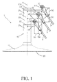
- FIG. 1 a first embodiment of the anchoring device according to the invention for mounting on a roof is shown.
- Three guide wires 3, 3', 3" are attached to the anchoring device 1 over which runners 5, 5', 5" are movable.
- a fuse cable 7, 7', 7" for a person is attached to each runner.
- the anchor device 1 has a base 11 to which a support 13 is attached and which is provided with a mounting surface 19 with which it is fixed on the roof.
- the base 11 and the support 13 have a rotation-symmetrical shape.
- the support is composed of parts 13a-d, between which carriers 15, 15', 15" are clamped.
- At the free ends 17, 17', 17" of the carriers wire guides are attached for holding the guide wires. So, people can pass each other without thereby having to be detaching from the guide wires.
- the carriers 15, 15', 15" are rotatably connected to the support 13 and can be fixed to the support in any desired position relative to the support.
- the wire guides 17, 17', 17" are at different distances d1 d2, d3 from the central axis 9 of the support 13. In a direction parallel to the mounting surface 19, the wire guides are at a distance D1 and D2 from one another, and in a direction at right angles to the mounting surface 19, the wire guides are at a distance D3 of each other.
- FIG 2 a second embodiment of the anchoring device according to the invention for mounting on a roof is shown in cross-section. All parts that have the same function as those shown in Figure 1 of the first embodiment are denoted by the same reference numerals.
- the wire guides 17 and 17' are at the same distance from the central axis 9 of the support 13 and the wire guide 17" is on top of the support 13 at the location of the center line 9.
- FIGs 3 and 4 a third embodiment of the anchoring device according to the invention is shown. All parts that have the same function as those shown in Figure 1 of the first embodiment are again indicated by the same reference numerals.
- This anchoring device 31 is designed for mounting on a wall or ceiling and has two wire guides 17 and 17' which are mounted on one carrier 15. This carrier is clamped between the two parts 13a and 13b of the support 13, whereby one of the parts 13b has a threaded end 35 which is tightened in a threaded hole in the other part 13a.
- To absorb a fall disc springs 33 are located in the part 13b. The wall portion around the disc spring will deform when a jerk is applied on the support 13 and then the disc springs absorb the fall energy partially.
- the cable guides 17 and 17' are at different distances d1 and d2 from the central axis 9 of the support 13. Also, in a direction parallel to the mounting surface 19 the wire guides are at a distance D1 from each other, and in a direction at right angles to the mounting surface 19 the wire guides are at a distance D3 of each other.
Landscapes
- Engineering & Computer Science (AREA)
- Architecture (AREA)
- Civil Engineering (AREA)
- Structural Engineering (AREA)
- Mechanical Engineering (AREA)
- Health & Medical Sciences (AREA)
- General Health & Medical Sciences (AREA)
- Business, Economics & Management (AREA)
- Emergency Management (AREA)
- Installation Of Indoor Wiring (AREA)
- Suspension Of Electric Lines Or Cables (AREA)
Abstract
Description
- The invention relates to an anchoring device for attaching at least two guide wires to a wall or ceiling or on a roof, on each of the guide wires a runner is movable with a fuse cable for a person attached to it, which anchoring device comprises a base provided with a mounting surface, as well as a support attached to the base and one or more carriers to which at least wire guides are mounted for holding the guide wires.
- Such an anchoring device is known from
WO 2008/151397 A . This known anchoring device has two spaced-apart wire guides, each of which hold a guide wire. Each guide wire is suitable for guiding one or more runners to which persons via fuse wires are attached. So, two people can pass each other without having to be detached from the guide wire. - An object of the invention is to provide an anchoring device of the kind described in the preamble which offers more possibilities for holding guide wires than the known anchoring device. To this end, the anchoring device according to the invention is characterized in that the carrier or carriers are rotatably connected to the support and can be fixed to the support in any desired position. Because the carriers to which the wire guides are attached can be rotated and fixed in any desired position relative to the support, the anchoring device according to the invention provides many options for holding the guide wires.
- The holding possibilities further increase when the support comprises at least two parts between which the carrier or carriers are present, wherein between two adjacent parts one or more carriers can be clamped.
- In case the base and support are rotation symmetrical the orientation of the base does not have to be taken into account when attaching the anchoring device on a roof or on a wall or ceiling.
- In order to let two people pass each other easily without the risk that the fuse wires interfere with each other, at least two of the wire guides are at different distances from the center line of the support. Furthermore for this purpose, in a direction parallel to the mounting plane at least two of the wire guides are at a distance from each other, and in a direction perpendicular to the mounting surface, at least two of the wire guides are preferably at a distance from each other.
- The invention will be elucidated more fully hereinbelow based on examples of embodiment of a flywheel module according to the invention either or not located in a drive mechanism of a vehicle while reference is made to the appended drawing figures, in which:
-
Figure 1 shows a first embodiment of the anchoring device according to the invention for mounting on a roof; -
Figure 2 shows a second embodiment of the anchoring device according to the invention for mounting on a roof; -
Figure 3 shows a third embodiment of the anchoring device according to the invention for mounting on a wall or ceiling, and -
Figure 4 shows the anchoring device shown inFigure 3 in side view. - In
Figure 1 , a first embodiment of the anchoring device according to the invention for mounting on a roof is shown. Threeguide wires runners fuse cable base 11 to which asupport 13 is attached and which is provided with amounting surface 19 with which it is fixed on the roof. Thebase 11 and thesupport 13 have a rotation-symmetrical shape. The support is composed ofparts 13a-d, between whichcarriers free ends - The
carriers support 13 and can be fixed to the support in any desired position relative to the support. Thewire guides central axis 9 of thesupport 13. In a direction parallel to themounting surface 19, the wire guides are at a distance D1 and D2 from one another, and in a direction at right angles to themounting surface 19, the wire guides are at a distance D3 of each other. - In
Figure 2 , a second embodiment of the anchoring device according to the invention for mounting on a roof is shown in cross-section. All parts that have the same function as those shown inFigure 1 of the first embodiment are denoted by the same reference numerals. In thisanchoring device 21, thewire guides 17 and 17' are at the same distance from thecentral axis 9 of thesupport 13 and thewire guide 17" is on top of thesupport 13 at the location of thecenter line 9. - In this cross section clearly can be seen that the
parts 13a-d are tightened against each other by abolt 23, and that in thelower part 13a, an energy-absorbingelement 25 is present. Thesupport 13 absorbs the energy of a person fallen. This person is captured with a jerk by thesupport 13 via thefuse cable 7 and theguide wire 3 and the energy of the fall is absorbed by the energy-absorbing element. Theelement 25 and the sleeve around this element will deform when a jerk is applied to thesupport 13 and thereby absorb energy. - In
Figures 3 and 4 a third embodiment of the anchoring device according to the invention is shown. All parts that have the same function as those shown inFigure 1 of the first embodiment are again indicated by the same reference numerals. Thisanchoring device 31 is designed for mounting on a wall or ceiling and has twowire guides 17 and 17' which are mounted on onecarrier 15. This carrier is clamped between the twoparts support 13, whereby one of theparts 13b has a threadedend 35 which is tightened in a threaded hole in theother part 13a. To absorb afall disc springs 33 are located in thepart 13b. The wall portion around the disc spring will deform when a jerk is applied on thesupport 13 and then the disc springs absorb the fall energy partially. - Also in this embodiment the
cable guides 17 and 17' are at different distances d1 and d2 from thecentral axis 9 of thesupport 13. Also, in a direction parallel to themounting surface 19 the wire guides are at a distance D1 from each other, and in a direction at right angles to themounting surface 19 the wire guides are at a distance D3 of each other. - Albeit the invention has been described in the foregoing with reference to the drawings, it should be observed that the invention is not by any manner or means restricted to the embodiments shown in the drawings. The invention also extends to all embodiments deviating from the embodiments shown in the drawings within the scope defined by the claims.
Claims (6)
- Anchoring device (1, 21, 31) for attaching at least two guide wires (3) to a wall or ceiling or on a roof, on each of the guide wires a runner (5) is movable with a fuse cable (7) for a person attached to it, which anchoring device comprises a base (11) provided with a mounting surface (19), as well as a support (13) attached to the base and one or more carriers (15, 15', 15") to which at least wire guides (17, 17' , 17") are mounted for holding the guide wires, characterized in that the carrier or carriers (15, 15', 15") are rotatably connected to the support (13) and can be fixed to the support in any desired position.
- Anchoring device (1, 21, 31) according to claim 1, characterized in that the support (13) comprises at least two parts (13a-d), between which the carrier or carriers (15) are present, wherein between two adjacent parts one or more carriers can be clamped.
- Anchoring device (1, 21, 31) according to claim 1 or 2, characterized in that the base (11) and the support (13) have a rotation-symmetrical shape.
- Anchoring device (1, 21, 31) according to claim 1, 2 or 3, characterized in that at least two of the wire guides (17, 17') are at different distances (d1 d2) from the center line (9) of the support (13).
- Anchoring device (1, 21, 31) according to any one of the preceding claims, characterized in that, in a direction parallel to the mounting surface (19) at least two of the wire guides (17, 17') are at a distance (D1) from each other.
- Anchoring device (1, 21, 31) according to any one of the preceding claims, characterized in that, in a direction at right angles to the mounting surface (19) at least two of the guide wires (17, 17') are at a distance (D3) from each other.
Applications Claiming Priority (1)
| Application Number | Priority Date | Filing Date | Title |
|---|---|---|---|
| NL2008121A NL2008121C2 (en) | 2012-01-13 | 2012-01-13 | ANCHORING DEVICE. |
Publications (3)
| Publication Number | Publication Date |
|---|---|
| EP2615225A2 true EP2615225A2 (en) | 2013-07-17 |
| EP2615225A3 EP2615225A3 (en) | 2015-09-16 |
| EP2615225B1 EP2615225B1 (en) | 2018-03-21 |
Family
ID=47501030
Family Applications (1)
| Application Number | Title | Priority Date | Filing Date |
|---|---|---|---|
| EP13151227.9A Active EP2615225B1 (en) | 2012-01-13 | 2013-01-14 | Anchoring device |
Country Status (3)
| Country | Link |
|---|---|
| US (1) | US9431809B2 (en) |
| EP (1) | EP2615225B1 (en) |
| NL (1) | NL2008121C2 (en) |
Cited By (3)
| Publication number | Priority date | Publication date | Assignee | Title |
|---|---|---|---|---|
| US20120267194A1 (en) * | 2009-09-02 | 2012-10-25 | Latchways Plc | Bracket Fixing For A Safety Line |
| KR20190056097A (en) * | 2017-11-16 | 2019-05-24 | 인하대학교 산학협력단 | Apparatus of life rope |
| US20220228388A1 (en) * | 2021-01-21 | 2022-07-21 | Rooftop Anchor, Inc. | Circular mounting device |
Families Citing this family (7)
| Publication number | Priority date | Publication date | Assignee | Title |
|---|---|---|---|---|
| NL1039209C2 (en) * | 2011-12-02 | 2013-06-06 | Xsplatforms B V | RUNNER FOR CONDUCTION ALONG A GUIDE CABLE OF AN ANCHORING DEVICE. |
| CA2922707C (en) * | 2013-09-06 | 2020-05-26 | 1078955 Bc Ltd. | Anchorage connector for a safety system |
| US10279247B2 (en) * | 2013-12-13 | 2019-05-07 | Masimo Corporation | Avatar-incentive healthcare therapy |
| US10508459B2 (en) * | 2014-09-19 | 2019-12-17 | Rooftop Anchor, Inc. | Tip-over post |
| US10118057B2 (en) * | 2016-04-29 | 2018-11-06 | Auburn University | Fall restraint system |
| US11311756B1 (en) * | 2018-04-17 | 2022-04-26 | Diadem Usa, Inc. | Ballasted fall prevention apparatus |
| US20230021139A1 (en) * | 2021-07-19 | 2023-01-19 | Nawar Kzeer | Roof Anchor |
Citations (1)
| Publication number | Priority date | Publication date | Assignee | Title |
|---|---|---|---|---|
| WO2008151397A1 (en) | 2007-06-13 | 2008-12-18 | Exponent Challenge Technology | Fall arrest assembly |
Family Cites Families (7)
| Publication number | Priority date | Publication date | Assignee | Title |
|---|---|---|---|---|
| US3312020A (en) * | 1964-05-08 | 1967-04-04 | Schuster Wilhelm | Collapsible columnar structure |
| US5297651A (en) * | 1993-04-28 | 1994-03-29 | Swingstage Limited | Safety load transfer device and system |
| US7537085B2 (en) * | 2003-04-07 | 2009-05-26 | Capital Safety Group Winnipeg Ltd. | Fall restraint anchoring post |
| NL1027728C2 (en) * | 2003-12-24 | 2005-07-05 | Kedge Holding Bv | Safety device installed on roof of object e.g. house, comprises flexible fastening flap that extends laterally between flange portions, for firm and durable connection to object |
| BE1016931A4 (en) * | 2005-06-14 | 2007-10-02 | Exponent Challenge Technology | IMPROVED MULTIPLE FALL PROTECTION WITH FLEXIBLE ANCHOR LINE. |
| US8025125B2 (en) * | 2006-11-03 | 2011-09-27 | D B Industries, Inc. | Anchor assembly |
| DE102009048058B4 (en) * | 2009-10-02 | 2012-02-16 | Hans-Jürgen Müller | Fastening device, in particular for a continuous self-locking system |
-
2012
- 2012-01-13 NL NL2008121A patent/NL2008121C2/en active
-
2013
- 2013-01-14 US US13/741,373 patent/US9431809B2/en active Active
- 2013-01-14 EP EP13151227.9A patent/EP2615225B1/en active Active
Patent Citations (1)
| Publication number | Priority date | Publication date | Assignee | Title |
|---|---|---|---|---|
| WO2008151397A1 (en) | 2007-06-13 | 2008-12-18 | Exponent Challenge Technology | Fall arrest assembly |
Cited By (5)
| Publication number | Priority date | Publication date | Assignee | Title |
|---|---|---|---|---|
| US20120267194A1 (en) * | 2009-09-02 | 2012-10-25 | Latchways Plc | Bracket Fixing For A Safety Line |
| US9687683B2 (en) * | 2009-09-02 | 2017-06-27 | Latchways Plc | Bracket fixing for a safety line |
| KR20190056097A (en) * | 2017-11-16 | 2019-05-24 | 인하대학교 산학협력단 | Apparatus of life rope |
| US20220228388A1 (en) * | 2021-01-21 | 2022-07-21 | Rooftop Anchor, Inc. | Circular mounting device |
| US11964174B2 (en) * | 2021-01-21 | 2024-04-23 | Rooftop Anchor, Inc. | Circular mounting device |
Also Published As
| Publication number | Publication date |
|---|---|
| EP2615225B1 (en) | 2018-03-21 |
| US20140027583A1 (en) | 2014-01-30 |
| NL2008121C2 (en) | 2013-07-16 |
| US9431809B2 (en) | 2016-08-30 |
| EP2615225A3 (en) | 2015-09-16 |
Similar Documents
| Publication | Publication Date | Title |
|---|---|---|
| EP2615225B1 (en) | Anchoring device | |
| EP2976484B1 (en) | Tether system for a safety line | |
| EP2940322B1 (en) | A suspension arrangement, and a monitoring device having a suspension arrangement | |
| US20100243837A1 (en) | Anchor point | |
| EP1602518A3 (en) | Power supply device for sliding door | |
| AU2014268101A1 (en) | Attachment element | |
| RU2452069C2 (en) | Support bracket intended for electric cables attachment on some structure | |
| EP2159412B1 (en) | Flange mounting for holding a tower section | |
| WO2001056884A3 (en) | Frangible actuator with redundant power supply | |
| CN110267714A (en) | Locating rings in external energy absorbers | |
| US10232201B2 (en) | Fall arrest apparatus | |
| JPS58152206A (en) | Anchor fitting | |
| US8158882B1 (en) | Electrical box hanger | |
| WO2010079344A8 (en) | Fall arrest system | |
| KR101837068B1 (en) | Tethered fastener apparatus and method | |
| CN1953103A (en) | Multifunctional mounting bracket for an electrical device | |
| US20130170113A1 (en) | Bracket and electronic device | |
| CN204213119U (en) | Belt securing means | |
| CN211335852U (en) | Special-shaped cable tie for automobile wire harness | |
| KR20140047421A (en) | Hanger for electric wire | |
| CN105221845A (en) | A kind of split route of pipe line sheath | |
| HUP0900466A2 (en) | Payload suspension system | |
| EP1926533B1 (en) | Energy absorber | |
| CN202503217U (en) | Portable hooking device | |
| US9371101B1 (en) | Bicycle parking rack featuring flexible rope wire |
Legal Events
| Date | Code | Title | Description |
|---|---|---|---|
| PUAI | Public reference made under article 153(3) epc to a published international application that has entered the european phase |
Free format text: ORIGINAL CODE: 0009012 |
|
| AK | Designated contracting states |
Kind code of ref document: A2 Designated state(s): AL AT BE BG CH CY CZ DE DK EE ES FI FR GB GR HR HU IE IS IT LI LT LU LV MC MK MT NL NO PL PT RO RS SE SI SK SM TR |
|
| AX | Request for extension of the european patent |
Extension state: BA ME |
|
| PUAL | Search report despatched |
Free format text: ORIGINAL CODE: 0009013 |
|
| AK | Designated contracting states |
Kind code of ref document: A3 Designated state(s): AL AT BE BG CH CY CZ DE DK EE ES FI FR GB GR HR HU IE IS IT LI LT LU LV MC MK MT NL NO PL PT RO RS SE SI SK SM TR |
|
| AX | Request for extension of the european patent |
Extension state: BA ME |
|
| RIC1 | Information provided on ipc code assigned before grant |
Ipc: A62B 35/00 20060101AFI20150812BHEP Ipc: E04G 21/32 20060101ALI20150812BHEP Ipc: H02G 3/30 20060101ALI20150812BHEP |
|
| 17P | Request for examination filed |
Effective date: 20160316 |
|
| RBV | Designated contracting states (corrected) |
Designated state(s): AL AT BE BG CH CY CZ DE DK EE ES FI FR GB GR HR HU IE IS IT LI LT LU LV MC MK MT NL NO PL PT RO RS SE SI SK SM TR |
|
| STAA | Information on the status of an ep patent application or granted ep patent |
Free format text: STATUS: EXAMINATION IS IN PROGRESS |
|
| 17Q | First examination report despatched |
Effective date: 20170413 |
|
| REG | Reference to a national code |
Ref country code: DE Ref legal event code: R079 Ref document number: 602013034593 Country of ref document: DE Free format text: PREVIOUS MAIN CLASS: E04G0021320000 Ipc: A62B0001040000 |
|
| GRAP | Despatch of communication of intention to grant a patent |
Free format text: ORIGINAL CODE: EPIDOSNIGR1 |
|
| STAA | Information on the status of an ep patent application or granted ep patent |
Free format text: STATUS: GRANT OF PATENT IS INTENDED |
|
| RIC1 | Information provided on ipc code assigned before grant |
Ipc: A62B 35/04 20060101ALI20171128BHEP Ipc: A62B 1/04 20060101AFI20171128BHEP Ipc: E04D 13/12 20060101ALI20171128BHEP Ipc: H02G 3/30 20060101ALI20171128BHEP Ipc: E04G 21/32 20060101ALI20171128BHEP Ipc: A62B 35/00 20060101ALI20171128BHEP |
|
| INTG | Intention to grant announced |
Effective date: 20171213 |
|
| GRAS | Grant fee paid |
Free format text: ORIGINAL CODE: EPIDOSNIGR3 |
|
| GRAA | (expected) grant |
Free format text: ORIGINAL CODE: 0009210 |
|
| STAA | Information on the status of an ep patent application or granted ep patent |
Free format text: STATUS: THE PATENT HAS BEEN GRANTED |
|
| AK | Designated contracting states |
Kind code of ref document: B1 Designated state(s): AL AT BE BG CH CY CZ DE DK EE ES FI FR GB GR HR HU IE IS IT LI LT LU LV MC MK MT NL NO PL PT RO RS SE SI SK SM TR |
|
| REG | Reference to a national code |
Ref country code: GB Ref legal event code: FG4D |
|
| REG | Reference to a national code |
Ref country code: CH Ref legal event code: EP |
|
| REG | Reference to a national code |
Ref country code: AT Ref legal event code: REF Ref document number: 980462 Country of ref document: AT Kind code of ref document: T Effective date: 20180415 |
|
| REG | Reference to a national code |
Ref country code: IE Ref legal event code: FG4D |
|
| REG | Reference to a national code |
Ref country code: DE Ref legal event code: R096 Ref document number: 602013034593 Country of ref document: DE |
|
| REG | Reference to a national code |
Ref country code: NL Ref legal event code: FP |
|
| PG25 | Lapsed in a contracting state [announced via postgrant information from national office to epo] |
Ref country code: HR Free format text: LAPSE BECAUSE OF FAILURE TO SUBMIT A TRANSLATION OF THE DESCRIPTION OR TO PAY THE FEE WITHIN THE PRESCRIBED TIME-LIMIT Effective date: 20180321 Ref country code: LT Free format text: LAPSE BECAUSE OF FAILURE TO SUBMIT A TRANSLATION OF THE DESCRIPTION OR TO PAY THE FEE WITHIN THE PRESCRIBED TIME-LIMIT Effective date: 20180321 Ref country code: CY Free format text: LAPSE BECAUSE OF FAILURE TO SUBMIT A TRANSLATION OF THE DESCRIPTION OR TO PAY THE FEE WITHIN THE PRESCRIBED TIME-LIMIT Effective date: 20180321 Ref country code: NO Free format text: LAPSE BECAUSE OF FAILURE TO SUBMIT A TRANSLATION OF THE DESCRIPTION OR TO PAY THE FEE WITHIN THE PRESCRIBED TIME-LIMIT Effective date: 20180621 Ref country code: FI Free format text: LAPSE BECAUSE OF FAILURE TO SUBMIT A TRANSLATION OF THE DESCRIPTION OR TO PAY THE FEE WITHIN THE PRESCRIBED TIME-LIMIT Effective date: 20180321 |
|
| REG | Reference to a national code |
Ref country code: LT Ref legal event code: MG4D |
|
| REG | Reference to a national code |
Ref country code: AT Ref legal event code: MK05 Ref document number: 980462 Country of ref document: AT Kind code of ref document: T Effective date: 20180321 |
|
| PG25 | Lapsed in a contracting state [announced via postgrant information from national office to epo] |
Ref country code: GR Free format text: LAPSE BECAUSE OF FAILURE TO SUBMIT A TRANSLATION OF THE DESCRIPTION OR TO PAY THE FEE WITHIN THE PRESCRIBED TIME-LIMIT Effective date: 20180622 Ref country code: BG Free format text: LAPSE BECAUSE OF FAILURE TO SUBMIT A TRANSLATION OF THE DESCRIPTION OR TO PAY THE FEE WITHIN THE PRESCRIBED TIME-LIMIT Effective date: 20180621 Ref country code: RS Free format text: LAPSE BECAUSE OF FAILURE TO SUBMIT A TRANSLATION OF THE DESCRIPTION OR TO PAY THE FEE WITHIN THE PRESCRIBED TIME-LIMIT Effective date: 20180321 Ref country code: SE Free format text: LAPSE BECAUSE OF FAILURE TO SUBMIT A TRANSLATION OF THE DESCRIPTION OR TO PAY THE FEE WITHIN THE PRESCRIBED TIME-LIMIT Effective date: 20180321 Ref country code: LV Free format text: LAPSE BECAUSE OF FAILURE TO SUBMIT A TRANSLATION OF THE DESCRIPTION OR TO PAY THE FEE WITHIN THE PRESCRIBED TIME-LIMIT Effective date: 20180321 |
|
| PG25 | Lapsed in a contracting state [announced via postgrant information from national office to epo] |
Ref country code: AL Free format text: LAPSE BECAUSE OF FAILURE TO SUBMIT A TRANSLATION OF THE DESCRIPTION OR TO PAY THE FEE WITHIN THE PRESCRIBED TIME-LIMIT Effective date: 20180321 Ref country code: RO Free format text: LAPSE BECAUSE OF FAILURE TO SUBMIT A TRANSLATION OF THE DESCRIPTION OR TO PAY THE FEE WITHIN THE PRESCRIBED TIME-LIMIT Effective date: 20180321 Ref country code: ES Free format text: LAPSE BECAUSE OF FAILURE TO SUBMIT A TRANSLATION OF THE DESCRIPTION OR TO PAY THE FEE WITHIN THE PRESCRIBED TIME-LIMIT Effective date: 20180321 Ref country code: PL Free format text: LAPSE BECAUSE OF FAILURE TO SUBMIT A TRANSLATION OF THE DESCRIPTION OR TO PAY THE FEE WITHIN THE PRESCRIBED TIME-LIMIT Effective date: 20180321 Ref country code: EE Free format text: LAPSE BECAUSE OF FAILURE TO SUBMIT A TRANSLATION OF THE DESCRIPTION OR TO PAY THE FEE WITHIN THE PRESCRIBED TIME-LIMIT Effective date: 20180321 |
|
| PG25 | Lapsed in a contracting state [announced via postgrant information from national office to epo] |
Ref country code: SM Free format text: LAPSE BECAUSE OF FAILURE TO SUBMIT A TRANSLATION OF THE DESCRIPTION OR TO PAY THE FEE WITHIN THE PRESCRIBED TIME-LIMIT Effective date: 20180321 Ref country code: AT Free format text: LAPSE BECAUSE OF FAILURE TO SUBMIT A TRANSLATION OF THE DESCRIPTION OR TO PAY THE FEE WITHIN THE PRESCRIBED TIME-LIMIT Effective date: 20180321 Ref country code: CZ Free format text: LAPSE BECAUSE OF FAILURE TO SUBMIT A TRANSLATION OF THE DESCRIPTION OR TO PAY THE FEE WITHIN THE PRESCRIBED TIME-LIMIT Effective date: 20180321 Ref country code: SK Free format text: LAPSE BECAUSE OF FAILURE TO SUBMIT A TRANSLATION OF THE DESCRIPTION OR TO PAY THE FEE WITHIN THE PRESCRIBED TIME-LIMIT Effective date: 20180321 |
|
| PG25 | Lapsed in a contracting state [announced via postgrant information from national office to epo] |
Ref country code: PT Free format text: LAPSE BECAUSE OF FAILURE TO SUBMIT A TRANSLATION OF THE DESCRIPTION OR TO PAY THE FEE WITHIN THE PRESCRIBED TIME-LIMIT Effective date: 20180723 |
|
| REG | Reference to a national code |
Ref country code: DE Ref legal event code: R097 Ref document number: 602013034593 Country of ref document: DE |
|
| PLBE | No opposition filed within time limit |
Free format text: ORIGINAL CODE: 0009261 |
|
| STAA | Information on the status of an ep patent application or granted ep patent |
Free format text: STATUS: NO OPPOSITION FILED WITHIN TIME LIMIT |
|
| PG25 | Lapsed in a contracting state [announced via postgrant information from national office to epo] |
Ref country code: DK Free format text: LAPSE BECAUSE OF FAILURE TO SUBMIT A TRANSLATION OF THE DESCRIPTION OR TO PAY THE FEE WITHIN THE PRESCRIBED TIME-LIMIT Effective date: 20180321 |
|
| 26N | No opposition filed |
Effective date: 20190102 |
|
| PG25 | Lapsed in a contracting state [announced via postgrant information from national office to epo] |
Ref country code: IT Free format text: LAPSE BECAUSE OF FAILURE TO SUBMIT A TRANSLATION OF THE DESCRIPTION OR TO PAY THE FEE WITHIN THE PRESCRIBED TIME-LIMIT Effective date: 20180321 |
|
| PG25 | Lapsed in a contracting state [announced via postgrant information from national office to epo] |
Ref country code: SI Free format text: LAPSE BECAUSE OF FAILURE TO SUBMIT A TRANSLATION OF THE DESCRIPTION OR TO PAY THE FEE WITHIN THE PRESCRIBED TIME-LIMIT Effective date: 20180321 |
|
| PG25 | Lapsed in a contracting state [announced via postgrant information from national office to epo] |
Ref country code: MC Free format text: LAPSE BECAUSE OF FAILURE TO SUBMIT A TRANSLATION OF THE DESCRIPTION OR TO PAY THE FEE WITHIN THE PRESCRIBED TIME-LIMIT Effective date: 20180321 |
|
| PG25 | Lapsed in a contracting state [announced via postgrant information from national office to epo] |
Ref country code: TR Free format text: LAPSE BECAUSE OF FAILURE TO SUBMIT A TRANSLATION OF THE DESCRIPTION OR TO PAY THE FEE WITHIN THE PRESCRIBED TIME-LIMIT Effective date: 20180321 |
|
| PG25 | Lapsed in a contracting state [announced via postgrant information from national office to epo] |
Ref country code: MT Free format text: LAPSE BECAUSE OF NON-PAYMENT OF DUE FEES Effective date: 20190114 |
|
| REG | Reference to a national code |
Ref country code: NL Ref legal event code: RE Free format text: SEIZURE, PRE-JUDGEMENT ATTACHEMENT Effective date: 20210216 |
|
| PG25 | Lapsed in a contracting state [announced via postgrant information from national office to epo] |
Ref country code: IS Free format text: LAPSE BECAUSE OF FAILURE TO SUBMIT A TRANSLATION OF THE DESCRIPTION OR TO PAY THE FEE WITHIN THE PRESCRIBED TIME-LIMIT Effective date: 20180721 |
|
| PG25 | Lapsed in a contracting state [announced via postgrant information from national office to epo] |
Ref country code: HU Free format text: LAPSE BECAUSE OF FAILURE TO SUBMIT A TRANSLATION OF THE DESCRIPTION OR TO PAY THE FEE WITHIN THE PRESCRIBED TIME-LIMIT; INVALID AB INITIO Effective date: 20130114 |
|
| REG | Reference to a national code |
Ref country code: NL Ref legal event code: RE Free format text: SEIZURE, PRE-JUDGEMENT ATTACHEMENT Effective date: 20220128 |
|
| REG | Reference to a national code |
Ref country code: NL Ref legal event code: RF Free format text: SEIZURE REMOVAL, PRE-JUDGEMENT ATTACHEMENT Effective date: 20220607 |
|
| PG25 | Lapsed in a contracting state [announced via postgrant information from national office to epo] |
Ref country code: MK Free format text: LAPSE BECAUSE OF FAILURE TO SUBMIT A TRANSLATION OF THE DESCRIPTION OR TO PAY THE FEE WITHIN THE PRESCRIBED TIME-LIMIT Effective date: 20180321 |
|
| P01 | Opt-out of the competence of the unified patent court (upc) registered |
Effective date: 20231211 |
|
| P03 | Opt-out of the competence of the unified patent court (upc) deleted | ||
| PGFP | Annual fee paid to national office [announced via postgrant information from national office to epo] |
Ref country code: GB Payment date: 20251128 Year of fee payment: 14 |
|
| REG | Reference to a national code |
Ref country code: CH Ref legal event code: U11 Free format text: ST27 STATUS EVENT CODE: U-0-0-U10-U11 (AS PROVIDED BY THE NATIONAL OFFICE) Effective date: 20260201 |
|
| PGFP | Annual fee paid to national office [announced via postgrant information from national office to epo] |
Ref country code: LU Payment date: 20260120 Year of fee payment: 14 Ref country code: NL Payment date: 20260120 Year of fee payment: 14 |
|
| PGFP | Annual fee paid to national office [announced via postgrant information from national office to epo] |
Ref country code: IE Payment date: 20260116 Year of fee payment: 14 Ref country code: DE Payment date: 20260122 Year of fee payment: 14 |
|
| PGFP | Annual fee paid to national office [announced via postgrant information from national office to epo] |
Ref country code: BE Payment date: 20260120 Year of fee payment: 14 |
|
| PGFP | Annual fee paid to national office [announced via postgrant information from national office to epo] |
Ref country code: FR Payment date: 20260120 Year of fee payment: 14 |
|
| PGFP | Annual fee paid to national office [announced via postgrant information from national office to epo] |
Ref country code: CH Payment date: 20260201 Year of fee payment: 14 |