EP2615033A2 - Clutch system for rotary-wing aircraft with secondary thrust system - Google Patents
Clutch system for rotary-wing aircraft with secondary thrust system Download PDFInfo
- Publication number
- EP2615033A2 EP2615033A2 EP12198637.6A EP12198637A EP2615033A2 EP 2615033 A2 EP2615033 A2 EP 2615033A2 EP 12198637 A EP12198637 A EP 12198637A EP 2615033 A2 EP2615033 A2 EP 2615033A2
- Authority
- EP
- European Patent Office
- Prior art keywords
- clutch
- synchronization
- time
- recited
- powerplant
- Prior art date
- Legal status (The legal status is an assumption and is not a legal conclusion. Google has not performed a legal analysis and makes no representation as to the accuracy of the status listed.)
- Withdrawn
Links
- 230000004044 response Effects 0.000 claims abstract description 15
- 238000000034 method Methods 0.000 claims description 10
- 239000002783 friction material Substances 0.000 claims description 4
- 239000000446 fuel Substances 0.000 claims description 4
- 238000004891 communication Methods 0.000 claims description 3
- 230000000694 effects Effects 0.000 claims 1
- 230000008901 benefit Effects 0.000 description 6
- 241000287828 Gallus gallus Species 0.000 description 4
- 230000006870 function Effects 0.000 description 4
- 239000000463 material Substances 0.000 description 4
- 230000008859 change Effects 0.000 description 3
- 238000013459 approach Methods 0.000 description 2
- 230000005540 biological transmission Effects 0.000 description 2
- 230000000875 corresponding effect Effects 0.000 description 2
- 239000003921 oil Substances 0.000 description 2
- 230000001360 synchronised effect Effects 0.000 description 2
- 238000013519 translation Methods 0.000 description 2
- RZVHIXYEVGDQDX-UHFFFAOYSA-N 9,10-anthraquinone Chemical compound C1=CC=C2C(=O)C3=CC=CC=C3C(=O)C2=C1 RZVHIXYEVGDQDX-UHFFFAOYSA-N 0.000 description 1
- 101100011382 Aspergillus niger eglB gene Proteins 0.000 description 1
- 101100285402 Danio rerio eng1a gene Proteins 0.000 description 1
- 101100285408 Danio rerio eng2a gene Proteins 0.000 description 1
- 101150067694 ENG1 gene Proteins 0.000 description 1
- 101100172294 Saccharomyces cerevisiae (strain ATCC 204508 / S288c) ACF2 gene Proteins 0.000 description 1
- 101100172292 Saccharomyces cerevisiae (strain ATCC 204508 / S288c) DSE4 gene Proteins 0.000 description 1
- 101100172293 Schizosaccharomyces pombe (strain 972 / ATCC 24843) eng2 gene Proteins 0.000 description 1
- 230000001133 acceleration Effects 0.000 description 1
- 239000007866 anti-wear additive Substances 0.000 description 1
- 150000001875 compounds Chemical class 0.000 description 1
- 238000012790 confirmation Methods 0.000 description 1
- 239000002826 coolant Substances 0.000 description 1
- 230000002596 correlated effect Effects 0.000 description 1
- 230000003111 delayed effect Effects 0.000 description 1
- 238000010586 diagram Methods 0.000 description 1
- 230000009977 dual effect Effects 0.000 description 1
- 230000002452 interceptive effect Effects 0.000 description 1
- 238000012986 modification Methods 0.000 description 1
- 230000004048 modification Effects 0.000 description 1
- 238000013021 overheating Methods 0.000 description 1
- 230000009467 reduction Effects 0.000 description 1
- 230000002441 reversible effect Effects 0.000 description 1
- 238000004088 simulation Methods 0.000 description 1
- 230000003068 static effect Effects 0.000 description 1
- 230000000153 supplemental effect Effects 0.000 description 1
- 230000007704 transition Effects 0.000 description 1
Images



Classifications
-
- B—PERFORMING OPERATIONS; TRANSPORTING
- B64—AIRCRAFT; AVIATION; COSMONAUTICS
- B64C—AEROPLANES; HELICOPTERS
- B64C27/00—Rotorcraft; Rotors peculiar thereto
- B64C27/04—Helicopters
- B64C27/12—Rotor drives
-
- B—PERFORMING OPERATIONS; TRANSPORTING
- B64—AIRCRAFT; AVIATION; COSMONAUTICS
- B64D—EQUIPMENT FOR FITTING IN OR TO AIRCRAFT; FLIGHT SUITS; PARACHUTES; ARRANGEMENT OR MOUNTING OF POWER PLANTS OR PROPULSION TRANSMISSIONS IN AIRCRAFT
- B64D35/00—Transmitting power from power plants to propellers or rotors; Arrangements of transmissions
- B64D35/04—Transmitting power from power plants to propellers or rotors; Arrangements of transmissions characterised by the transmission driving a plurality of propellers or rotors
-
- B—PERFORMING OPERATIONS; TRANSPORTING
- B64—AIRCRAFT; AVIATION; COSMONAUTICS
- B64C—AEROPLANES; HELICOPTERS
- B64C27/00—Rotorcraft; Rotors peculiar thereto
- B64C27/04—Helicopters
- B64C27/08—Helicopters with two or more rotors
- B64C27/10—Helicopters with two or more rotors arranged coaxially
-
- B—PERFORMING OPERATIONS; TRANSPORTING
- B64—AIRCRAFT; AVIATION; COSMONAUTICS
- B64C—AEROPLANES; HELICOPTERS
- B64C27/00—Rotorcraft; Rotors peculiar thereto
- B64C27/22—Compound rotorcraft, i.e. aircraft using in flight the features of both aeroplane and rotorcraft
Definitions
- the present disclosure relates to a drive system suitable for use with a rotary-wing aircraft, and more particularly to a clutch system therefor.
- Automated power shifts in wet clutch system applications are typically controlled to millisecond length time periods and are completed within 10ths of a second. Such synchronization pulls energy from inertias in the system to achieve a desired shift quality.
- An aircraft includes a powerplant system operable to power a main rotor system and a secondary thrust system, the secondary thrust system is selectively driven through operation of a clutch system, and a clutch system synchronization time corresponds to a response time of the powerplant system,
- a method of operating a rotary wing aircraft with a secondary thrust system includes selectively engaging a secondary thrust system over a clutch synchronization time corresponding to a response time of a powerplant system.
- FIG 1 schematically illustrates an exemplary high speed vertical takeoff and landing (VTOL) rotary-wing aircraft 10 having a counter-rotating, coaxial rotor system 12 which rotates about an axis of rotation A.
- the aircraft 10 includes an airframe 14 which supports a drive system 16 ( Figure 2 ) that generally includes the rotor system 12, a powertrain system 24, a power plant system 26, and a secondary thrust system 30, which may also be considered a rotor system or powered system.
- the secondary thrust system 30 provides secondary thrust generally parallel to an aircraft longitudinal axis L while the main rotor system 12 operates in an unloaded reverse flow state during a high-speed forward flight profile.
- the main rotor systems 12 includes an upper rotor system 18A and a lower rotor system 18B.
- Each rotor system 18A, 18B includes a multiple of rotor blades 20 mounted to a respective rotor hub 22A, 22B for rotation about a rotor axis of rotation A. Any number of blades 20 may be used with the rotor system 12.
- the powertrain system 24 interconnects the powerplant system 26, the rotor system 12 and the secondary thrust system 30.
- the powertrain system 24 may include various gear systems such as main and combiner gearboxes.
- the powerplant system 26 generates the power available for flight operations to power the main rotor system 12 and the secondary thrust system 30 through the powertrain system 24.
- the powerplant system 26 in the disclosed, non-limiting embodiment includes two engine packages ENG1, ENG2, in communication with a fuel system F, however, single engine systems as well as multi-engine systems will also benefit herefrom.
- the secondary thrust system 30 in one non-limiting embodiment may be mounted to the rear of the airframe 14 transverse to the axis of rotation A with a rotational axis T thereof oriented substantially horizontal and parallel to an aircraft longitudinal axis L to provide thrust for high-speed flight. It should be understood that other configurations of the secondary thrust system 30 such as a propeller system mounted to each side of the airframe, a lift fan system, or other system may alternatively be utilized. In this disclosed, non-limiting embodiment, the secondary thrust system 30 includes a pusher propeller system 32.
- the powertrain system 24 may include a clutch system 34C (illustrated schematically) for selective operation of the secondary thrust system 30.
- the clutch system 34C is operable to control the engagement characteristics of the propeller system 32 with the powerplant system 26 to minimize the impact upon the operational speed of the ain rotor system 12.
- the clutch system 34C engagement characteristics the energy required to synchronize the propeller system 32 to the powertrain system 24 is obtained from the powerplant system 26. That is, engagement of the propeller system 32 through the clutch system 34C accelerates the propeller system 32 but does not cause a change in power provided by the main rotor system 12. Selection of, for example only, clutch system friction materials, engagement times and application rates permit the propeller system 32 to be synchronized to the powertrain system 24 in an elapsed time equal to or greater than the response time of the powerplant system 26.
- the maximum additional system energy required to power the propeller system 32 can be calculated as the change in system kinetic energy in which:
- This quantity of energy is dissipated within the clutch system 34C at a slipping speed.
- the clutch system 34C torque and the resultant energy rate (ft.lbf./sec) are controlled through variance, for example, of clutch system 34C pressure plate clamping load. That is, the propeller system 32 speed synchronization through the clutch system 34C is intentionally delayed to allow the powerplant system 26 to respond to the additional power demand.
- the spin up time lag of the powerplant system 26 is thereby correlated to an engagement time of the clutch system 34C through an extended slip period which, in the disclosed non-limiting embodiment, is greater than one second and most preferably between 2-3 seconds.
- the energy dissipated in the clutch system 34C and propeller system 32 is thereby provided from the powerplant system 26 and not from the momentum provided by the powertrain system 24. Coolant flow or other systems through the clutch system 34C may be utilize to prevent the clutch system 34C from overheating during the extended slip period.
- selective operation of the secondary thrust system 30 may be performed through a secondary thrust system algorithm 40 which controls, for example, the piston pressure within the clutch system 34C ( Figure 4 ).
- the functions of the secondary thrust system algorithm 40 are disclosed in terms of functional block diagrams, and it should be understood by those skilled in the art with the benefit of this disclosure that these functions may be enacted in either dedicated hardware circuitry or programmed software routines capable of execution in a microprocessor based electronics control embodiment such as a control module M, or a combination thereof.
- the secondary thrust system algorithm 40 controls functions 40A-F.
- Functions 40A-F include, respectively, engaging a translation thrust system (e.g., secondary thrust system 30), applying clutch system piston pressure over a time period which corresponds with powerplant system 26 spin-up, synchronizing translation thrust system with the powerplant system 26 through the clutch system 34C, a time delay, increasing clutch system piston pressure to maximum and permitting pitch control of the translational thrust system.
- a translation thrust system e.g., secondary thrust system 30
- clutch system piston pressure e.g., a time period which corresponds with powerplant system 26 spin-up
- synchronizing translation thrust system with the powerplant system 26 through the clutch system 34C a time delay
- increasing clutch system piston pressure to maximum and permitting pitch control of the translational thrust system.
- the control module M typically includes a processor, a memory and an interface.
- the processor may, for example only, be any type of known microprocessor having desired performance characteristics.
- the memory may, for example only, includes UVPROM, EEPROM, FLASH, RAM, ROM, DVD, CD, a hard drive, or other computer readable medium which may store data and the control algorithms for operation of the secondary thrust system algorithm 40 as described herein.
- the interface facilitates communication with the other avionics and systems,
- the control module M may be a portion of a flight control computer, a portion of a central vehicle control, an interactive vehicle dynamics module, a stand-alone line simulation unit or other system.
- the drive system 16 ( Figure 2 ) includes the clutch system 34C, which is operable to selectively engage and drive a rotor system, such as the secondary thrust system 30.
- a controller such as the control module M, is operable to selectively engage the clutch system 34C with a predetermined time lag, as described in the examples above.
- the clutch apply piston pressure in one disclosed, non-limiting embodiment is controlled to increase from 0 to about 25 psi (3.63 kPa) on a linear basis over about 3 seconds.
- Clutch ( Figure 5 ) relatively slowly over the initial 3 to correspond with the powerplant system 26 fuel response time which, in the disclosed, non-limiting embodiment is about 2 seconds plus a confirmation time delay of about 1 second.
- this ramp up need not be linear, however, the linear ramp up results in a parabolic shaped energy rate curve ( Figure 6 ). That is, the shape of the clutch energy rate curve is controlled by the clutc apply pressure curve and a linear increase provides a desired RPM output increase to the propeller system 32 ( Figure 7 ).
- the parabolic energy rate shape peaks at a time other than the synchronization time which is at about 2.5 seconds ( Figure 5 ). That is, the clutch system 34C is still slipping at the peak energy rate transmission of about 1.4 seconds.
- the clutch system 34 synchronization torque also occurs at a relatively low clutch apply piston pressure of about 35 psi (5 kPa) which provides a clutc torque of about 300 ft.lbs. (41.5 m-kg) to avoid energy draw and reduction in power from the powertrain system 24 which may otherwise result in a rotor droop condition for the main rotor system 12.
- the propeller system 32 is initially synchronized at a very low clutch system 34C capacity then significantly increased to, for example, almost 2000 ft. lbs (277 m-kgs), once synchronization is achieved.
- the initial synchronization torque occurs a relatively low pressure then only after synchronization is the clutch apply piston pressure increased to the full transmission capacity across the clutch system 34C - about 190psi (27.6 kPa) to provide, in the disclosed, non-limiting embodiment, the about 2000 ft.lbs (277 m-kgs) maximum operating capacity.
- synchronization occurs at 2.5 - 2.8 seconds, a slight time delay may be included such that application of clutch apply piston pressure does not initiate until after approximately 3 seconds, Significant clutch apply piston pressures permits, for example, rapid pitch changes for a controlled pitch propeller system 32 to facilitate aircraft acceleration response.
- a conventional friction coefficient has a fairly constant value versus slip speed until approach of synchronization. As zero slip speed approaches, the friction coefficient rises rapidly, then drops off. This transition from dynamic to static friction is referred to as a "rooster tail.”
- the "rooster tail” is avoided by the clutch system 34C through precise engagement thereof and material selection to avoid the “rooster tail” torque spike that would otherwise pull down the inertia of the system.
- Precise control of engagement may be provided through, for example, selection of friction materials which display minimal variation in friction coefficient across the operating slip range; assurance that the synchronization time exceeds the engine fuel system F response time to allow the powerplant system 26 to control/maintain system speed; selection of the appropriate rate of change in clutch system torque to meet/exceed synchronization time; and through the selection of clutch system 34C features such as number of friction surfaces, clamping piston size, housing and backing plate stiffness, are made to meet the synchronization thermal loads while also producing the large torque capacity required after synchronization. It should be appreciated that one or more of the above parameters may be controlled in accordance with the teachings herein to provide the desired aircraft response.
- Rotary wing aircraft utilize particular oils, such as DOD-L-85734, that include significant anti-wear additives with which a clutch disk friction material such as BW4300 has been selected in the disclosed non-limiting embodiment to provide one example which achieves minimal variation in the friction coefficient across the operating slip or the clutch system 34C to avoid a "rooster tail.” It should be appreciated, however, that other combinations of materials for other slip ranges and torque capacities may be determined based on factors such as friction characteristics, material/oil compatibility, friction vs. slip relationship, and material thermal durability.
Landscapes
- Engineering & Computer Science (AREA)
- Mechanical Engineering (AREA)
- Aviation & Aerospace Engineering (AREA)
- Hydraulic Clutches, Magnetic Clutches, Fluid Clutches, And Fluid Joints (AREA)
Abstract
Description
- The present disclosure relates to a drive system suitable for use with a rotary-wing aircraft, and more particularly to a clutch system therefor.
- Automated power shifts in wet clutch system applications are typically controlled to millisecond length time periods and are completed within 10ths of a second. Such synchronization pulls energy from inertias in the system to achieve a desired shift quality.
- An aircraft according to an exemplary aspect of the present disclosure includes a powerplant system operable to power a main rotor system and a secondary thrust system, the secondary thrust system is selectively driven through operation of a clutch system, and a clutch system synchronization time corresponds to a response time of the powerplant system,
- A method of operating a rotary wing aircraft with a secondary thrust system according to an exemplary aspect of the present disclosure includes selectively engaging a secondary thrust system over a clutch synchronization time corresponding to a response time of a powerplant system.
- Various features will become apparent to those skilled in the art from the following detailed description of the disclosed non-limiting embodiment, The drawings that accompany the detailed description can be briefly described as follows:
-
Figures 1 is a general schematic view of an exemplary rotary wing aircraft embodiment for use with the disclosure; -
Figure 2 is a general schematic view of a drive system for the rotary wing aircraft; -
Figure 3 is a secondary thrust system engagement flowchart; -
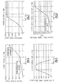
Figure 4 is a clutch apply piston pressure vs. time chart; -
Figure 5 is a clutch torque vs. time chart; -
Figure 6 is a clutch energy rate vs. time chart; -
Figure 7 is a secondary thrust system RPM vs. time chart; and -
Figure 8 is a clutch friction coefficient vs. slip speed chart. -
Figure 1 schematically illustrates an exemplary high speed vertical takeoff and landing (VTOL) rotary-wing aircraft 10 having a counter-rotating,coaxial rotor system 12 which rotates about an axis of rotation A. Theaircraft 10 includes anairframe 14 which supports a drive system 16 (Figure 2 ) that generally includes therotor system 12, apowertrain system 24, apower plant system 26, and asecondary thrust system 30, which may also be considered a rotor system or powered system. Thesecondary thrust system 30 provides secondary thrust generally parallel to an aircraft longitudinal axis L while themain rotor system 12 operates in an unloaded reverse flow state during a high-speed forward flight profile. Although a particular aircraft configuration is illustrated and described in the disclosed embodiment, other configurations and/or machines, such as high speed compound rotary-wing aircraft with supplemental thrust systems, dual contra-rotating, coaxial rotor system aircraft, turbo-props, tilt-rotor, tilt-wing aircraft and non-aircra applications will also benefit herefrom. Additionally, given this description, one of ordinary skill in the art will recognize that other types of drive systems, which may or may not be in aircraft, will also benefit from the examples herein. - The
main rotor systems 12 includes anupper rotor system 18A and alower rotor system 18B. Eachrotor system rotor blades 20 mounted to arespective rotor hub 22A, 22B for rotation about a rotor axis of rotation A. Any number ofblades 20 may be used with therotor system 12. - With reference to
Figure 2 , thepowertrain system 24 interconnects thepowerplant system 26, therotor system 12 and thesecondary thrust system 30. Thepowertrain system 24 may include various gear systems such as main and combiner gearboxes. Thepowerplant system 26 generates the power available for flight operations to power themain rotor system 12 and thesecondary thrust system 30 through thepowertrain system 24. Thepowerplant system 26 in the disclosed, non-limiting embodiment includes two engine packages ENG1, ENG2, in communication with a fuel system F, however, single engine systems as well as multi-engine systems will also benefit herefrom. - The
secondary thrust system 30 in one non-limiting embodiment may be mounted to the rear of theairframe 14 transverse to the axis of rotation A with a rotational axis T thereof oriented substantially horizontal and parallel to an aircraft longitudinal axis L to provide thrust for high-speed flight. It should be understood that other configurations of thesecondary thrust system 30 such as a propeller system mounted to each side of the airframe, a lift fan system, or other system may alternatively be utilized. In this disclosed, non-limiting embodiment, thesecondary thrust system 30 includes apusher propeller system 32. - The
powertrain system 24 may include aclutch system 34C (illustrated schematically) for selective operation of thesecondary thrust system 30. Theclutch system 34C is operable to control the engagement characteristics of thepropeller system 32 with thepowerplant system 26 to minimize the impact upon the operational speed of theain rotor system 12. - The
clutch system 34C engagement characteristics the energy required to synchronize thepropeller system 32 to thepowertrain system 24 is obtained from thepowerplant system 26. That is, engagement of thepropeller system 32 through theclutch system 34C accelerates thepropeller system 32 but does not cause a change in power provided by themain rotor system 12. Selection of, for example only, clutch system friction materials, engagement times and application rates permit thepropeller system 32 to be synchronized to thepowertrain system 24 in an elapsed time equal to or greater than the response time of thepowerplant system 26. - The maximum additional system energy required to power the
propeller system 32 can be calculated as the change in system kinetic energy in which: - Initial propeller speed= ω1 radians/sec = 0
- Effective propeller inertia = I x-x 1bs. ft. s^2
- Final propeller speed = ω2 radians/sec
- Total energy required to synchronize the speed of the
propeller system 32 to theclutch system 34C input speed = ½ I x-x (ω2)^2 - This quantity of energy is dissipated within the
clutch system 34C at a slipping speed. - The
instantaneous clutch system 34C power is determined by the following equation:
- The
clutch system 34C torque and the resultant energy rate (ft.lbf./sec) are controlled through variance, for example, ofclutch system 34C pressure plate clamping load. That is, thepropeller system 32 speed synchronization through theclutch system 34C is intentionally delayed to allow thepowerplant system 26 to respond to the additional power demand. The spin up time lag of thepowerplant system 26 is thereby correlated to an engagement time of theclutch system 34C through an extended slip period which, in the disclosed non-limiting embodiment, is greater than one second and most preferably between 2-3 seconds. The energy dissipated in theclutch system 34C andpropeller system 32 is thereby provided from thepowerplant system 26 and not from the momentum provided by thepowertrain system 24. Coolant flow or other systems through theclutch system 34C may be utilize to prevent theclutch system 34C from overheating during the extended slip period. - With reference to
Figure 3 , selective operation of thesecondary thrust system 30 may be performed through a secondarythrust system algorithm 40 which controls, for example, the piston pressure within theclutch system 34C (Figure 4 ). The functions of the secondarythrust system algorithm 40 are disclosed in terms of functional block diagrams, and it should be understood by those skilled in the art with the benefit of this disclosure that these functions may be enacted in either dedicated hardware circuitry or programmed software routines capable of execution in a microprocessor based electronics control embodiment such as a control module M, or a combination thereof. - In the illustrated example, the secondary
thrust system algorithm 40 controls functions 40A-F. Functions 40A-F include, respectively, engaging a translation thrust system (e.g., secondary thrust system 30), applying clutch system piston pressure over a time period which corresponds withpowerplant system 26 spin-up, synchronizing translation thrust system with thepowerplant system 26 through theclutch system 34C, a time delay, increasing clutch system piston pressure to maximum and permitting pitch control of the translational thrust system. - The control module M typically includes a processor, a memory and an interface. The processor may, for example only, be any type of known microprocessor having desired performance characteristics. The memory may, for example only, includes UVPROM, EEPROM, FLASH, RAM, ROM, DVD, CD, a hard drive, or other computer readable medium which may store data and the control algorithms for operation of the secondary
thrust system algorithm 40 as described herein. The interface facilitates communication with the other avionics and systems, In one non-limiting embodiment, the control module M may be a portion of a flight control computer, a portion of a central vehicle control, an interactive vehicle dynamics module, a stand-alone line simulation unit or other system. - In another embodiment, the drive system 16 (
Figure 2 ) includes theclutch system 34C, which is operable to selectively engage and drive a rotor system, such as thesecondary thrust system 30. A controller, such as the control module M, is operable to selectively engage theclutch system 34C with a predetermined time lag, as described in the examples above. - With reference to
Figure 4 , the clutch apply piston pressure in one disclosed, non-limiting embodiment, is controlled to increase from 0 to about 25 psi (3.63 kPa) on a linear basis over about 3 seconds. Clutch (Figure 5 ) relatively slowly over the initial 3 to correspond with thepowerplant system 26 fuel response time which, in the disclosed, non-limiting embodiment is about 2 seconds plus a confirmation time delay of about 1 second. It should be appreciate that this ramp up need not be linear, however, the linear ramp up results in a parabolic shaped energy rate curve (Figure 6 ). That is, the shape of the clutch energy rate curve is controlled by the clutc apply pressure curve and a linear increase provides a desired RPM output increase to the propeller system 32 (Figure 7 ). Notably, the parabolic energy rate shape peaks at a time other than the synchronization time which is at about 2.5 seconds (Figure 5 ). That is, theclutch system 34C is still slipping at the peak energy rate transmission of about 1.4 seconds. - The clutch system 34 synchronization torque also occurs at a relatively low clutch apply piston pressure of about 35 psi (5 kPa) which provides a clutc torque of about 300 ft.lbs. (41.5 m-kg) to avoid energy draw and reduction in power from the
powertrain system 24 which may otherwise result in a rotor droop condition for themain rotor system 12. Thepropeller system 32 is initially synchronized at a very lowclutch system 34C capacity then significantly increased to, for example, almost 2000 ft. lbs (277 m-kgs), once synchronization is achieved. That is, the initial synchronization torque occurs a relatively low pressure then only after synchronization is the clutch apply piston pressure increased to the full transmission capacity across theclutch system 34C - about 190psi (27.6 kPa) to provide, in the disclosed, non-limiting embodiment, the about 2000 ft.lbs (277 m-kgs) maximum operating capacity. Although synchronization occurs at 2.5 - 2.8 seconds, a slight time delay may be included such that application of clutch apply piston pressure does not initiate until after approximately 3 seconds, Significant clutch apply piston pressures permits, for example, rapid pitch changes for a controlledpitch propeller system 32 to facilitate aircraft acceleration response. - With reference to
Figure 8 , a conventional friction coefficient has a fairly constant value versus slip speed until approach of synchronization. As zero slip speed approaches, the friction coefficient rises rapidly, then drops off. This transition from dynamic to static friction is referred to as a "rooster tail." The "rooster tail" is avoided by theclutch system 34C through precise engagement thereof and material selection to avoid the "rooster tail" torque spike that would otherwise pull down the inertia of the system. - Precise control of engagement may be provided through, for example, selection of friction materials which display minimal variation in friction coefficient across the operating slip range; assurance that the synchronization time exceeds the engine fuel system F response time to allow the
powerplant system 26 to control/maintain system speed; selection of the appropriate rate of change in clutch system torque to meet/exceed synchronization time; and through the selection ofclutch system 34C features such as number of friction surfaces, clamping piston size, housing and backing plate stiffness, are made to meet the synchronization thermal loads while also producing the large torque capacity required after synchronization. It should be appreciated that one or more of the above parameters may be controlled in accordance with the teachings herein to provide the desired aircraft response. - Rotary wing aircraft utilize particular oils, such as DOD-L-85734, that include significant anti-wear additives with which a clutch disk friction material such as BW4300 has been selected in the disclosed non-limiting embodiment to provide one example which achieves minimal variation in the friction coefficient across the operating slip or the
clutch system 34C to avoid a "rooster tail." It should be appreciated, however, that other combinations of materials for other slip ranges and torque capacities may be determined based on factors such as friction characteristics, material/oil compatibility, friction vs. slip relationship, and material thermal durability. - It should be understood that relative positional terms such as "forward," "aft," "upper, "lower," "above," "below," and the like are with reference to the normal operational attitude of the vehicle and should not be considered otherwise limiting. Although the different non-limiting embodiments have specific illustrated components, the embodiments of this invention are not limited to those particular combinations. It is possible to use some of the components or features from any of the non-limiting embodiments in combination with features or components from any of the other non-limiting embodiments.
- It should be understood that like reference numerals identify corresponding or similar elements throughout the several drawings. It should be understood that although a particular component arrangement is disclosed in the illustrated embodiment, other arrangements will benefit herefrom.
- Although particular step sequences are shown, described, and claimed, it should be understood that steps may be performed in any order, separated or combined unless otherwise indicated and will still benefit from the present disclosure.
- The foregoing description is exemplary rather than defined by the limitations within. Various non-limiting embodiments are disclosed herein, however, one of ordinary skill in the art would recognize that various modifications and variations in light of the above teachings will fall within the scope of the appended claims. It is therefore to be understood that within the scope of the appended claims, the disclosure may be practiced other than as specifically described. For that reason the appended claims should be studied to determine true scope and content.
Claims (15)
- An aircraft (10) comprising:a main rotor system (12);a secondary thrust system (30); anda powerplant system (26) operable to power said main rotor system (12) and said secondary thrust system (30), said secondary thrust system selectively driven through operation of a clutch system (34C), said clutch system including a synchronization time that corresponds to a response time of said powerplant system (26).
- The aircraft (10) as recited in claim 1, wherein said clutch system (34C) synchronization time and said response time of said powerplant system (26) is greater than about 1 second, and preferably wherein said clutch system (34C) synchronization time and said response time of said powerplant system (26) is less than about 3 seconds.
- The aircraft as recited in claim 1, wherein said clutch system (34C) synchronization time and said response time of said powerplant system (26) is between 2 and 3 seconds, or wherein essentially all of energy used to synchronize said clutch system (34C) is pulled from said powerplant system (26) and has essentially no effect upon a speed of said main rotor system, or wherein said main rotor system axis of rotation is transverse to said secondary thrust system axis of rotation, or wherein said clutch system (34C) includes a BW4300 friction material.
- A method of operating a rotary wing aircraft (10) with a secondary thrust system (30) comprising:selectively engaging a secondary thrust system (30) over a clutch synchronization time corresponding to a response time of a powerplant system (26) of the rotary wing aircraft.
- The method as recited in claim 4, further comprising:defining the response time of the powerplant system (26) with respect to a time delay for an increase in fuel to the powerplant system.
- The method as recited in claim 4, further comprising:defining the clutch synchronization time to be greater than 1 second, or defining the clutch synchronization time to be between 2-3 seconds.
- The method as recited in claim 4, further comprising:increasing a clutch apply piston pressure over time to define a first synchronization rate until clutch synchronization; andincreasing the clutch apply piston pressure over time to define a second synchronization rate after clutch synchronization.
- The method as recited in claim 7, further comprising:defining the first synchronization rate to be less than the second synchronization rate.
- The method as recited in claim 7, further comprising:defining the first synchronization rate to occur over the clutch synchronization time of between 2-3 seconds.
- The method as recited in claim 7, further comprising:defining the second synchronization rate to occur over a time less than 3 seconds.
- The method as recited in claim 7, further comprising:increasing the clutch apply piston pressure over time to define the first synchronization rate to achieve a clutch torque less than 500 ft.lbs; andincreasing the clutch apply piston pressure over time to define the second synchronization rate to achieve a clutch torque greater than 2000 ft.lbs.
- The method as recited in claim 7, further comprising:increasing the clutch apply piston pressure to less than 40psi until clutch synchronization; andincreasing the clutch apply piston pressure to greater than 180psi after clutch synchronization.
- A drive system comprising:a clutch system (34C) operable to be selectively engaged to drive a powered system; anda controller in communication with said clutch system (34C) to control operation thereof, said controller being configured to selectively engage said clutch system with a controlled, predefined time lag.
- The drive system as recited in claim 13, wherein the controlled, predefined time lag corresponds to a response time of a powerplant system (26) that drives the powered system through said clutch system (34C).
- The drive system as recited in claim 13, wherein the powered system is a secondary thrust system (30).
Applications Claiming Priority (1)
| Application Number | Priority Date | Filing Date | Title |
|---|---|---|---|
| US13/349,059 US8827204B2 (en) | 2012-01-12 | 2012-01-12 | Clutch system for rotary-wing aircraft with secondary thrust system |
Publications (2)
| Publication Number | Publication Date |
|---|---|
| EP2615033A2 true EP2615033A2 (en) | 2013-07-17 |
| EP2615033A3 EP2615033A3 (en) | 2016-08-10 |
Family
ID=47632730
Family Applications (1)
| Application Number | Title | Priority Date | Filing Date |
|---|---|---|---|
| EP12198637.6A Withdrawn EP2615033A3 (en) | 2012-01-12 | 2012-12-20 | Clutch system for rotary-wing aircraft with secondary thrust system |
Country Status (2)
| Country | Link |
|---|---|
| US (1) | US8827204B2 (en) |
| EP (1) | EP2615033A3 (en) |
Cited By (4)
| Publication number | Priority date | Publication date | Assignee | Title |
|---|---|---|---|---|
| GB2520383A (en) * | 2013-09-19 | 2015-05-20 | Boeing Co | Contra-rotating open fan propulsion system |
| EP2947014A1 (en) * | 2014-05-23 | 2015-11-25 | Robby Moto Engineering S.r.l. | Propulsion device for helicopters |
| EP2947013A1 (en) * | 2014-05-23 | 2015-11-25 | Robby Moto Engineering S.r.l. | Helicopter |
| CN108516083A (en) * | 2018-03-27 | 2018-09-11 | 西北工业大学 | Double disengaging type stoppable rotor aircraft drive systems and change operating mode method |
Families Citing this family (6)
| Publication number | Priority date | Publication date | Assignee | Title |
|---|---|---|---|---|
| US10611472B2 (en) * | 2013-10-15 | 2020-04-07 | Sikorsky Aircraft Corporation | Coaxial rotor yaw control |
| WO2016053408A1 (en) * | 2014-10-01 | 2016-04-07 | Sikorsky Aircraft Corporation | Acoustic signature variation of aircraft utilizing a clutch |
| US10414512B2 (en) * | 2014-10-01 | 2019-09-17 | Sikorsky Aircraft Corporation | Power management between a propulsor and a coaxial rotor of a helicopter |
| WO2016054209A1 (en) | 2014-10-01 | 2016-04-07 | Sikorsky Aircraft Corporation | Dual rotor, rotary wing aircraft |
| US11781476B2 (en) * | 2019-06-25 | 2023-10-10 | Pratt & Whitney Canada Corp. | System and method for operating a multi-engine rotorcraft |
| US20250058870A1 (en) * | 2022-01-14 | 2025-02-20 | Roze Mobility | Hybrid-use rotary-wing aircraft with aligned drivetrain |
Family Cites Families (24)
| Publication number | Priority date | Publication date | Assignee | Title |
|---|---|---|---|---|
| US1851146A (en) | 1930-03-20 | 1932-03-29 | Continental Illinois Bank & Tr | Automatic clutch |
| US3679033A (en) * | 1970-11-30 | 1972-07-25 | Gen Motors Corp | Propeller coupling |
| US3677378A (en) * | 1970-12-28 | 1972-07-18 | Bendix Corp | Self-energizing torque limiting disc clutch |
| US3977812A (en) * | 1975-11-17 | 1976-08-31 | The United States Of America As Represented By The Secretary Of The Army | Compound helicopter drive means |
| US4046235A (en) | 1976-04-19 | 1977-09-06 | Western Gear Corporation | Automatic load brake |
| US4216848A (en) | 1977-09-06 | 1980-08-12 | Hitachi, Ltd. | Centrifugal braking device |
| US4219107A (en) | 1977-12-13 | 1980-08-26 | Nasa | Speed control device for a heavy duty shaft |
| US4632081A (en) * | 1983-08-01 | 1986-12-30 | Giuliani Robert L | Giuliani modular engine improvement |
| US4798052A (en) | 1987-05-08 | 1989-01-17 | Allied-Signal Inc. | Constant-clearance brake piston system with braking pressure intensifier |
| JP3100216B2 (en) | 1991-07-18 | 2000-10-16 | 株式会社シマノ | Brake mechanism for fishing reel |
| IT1267971B1 (en) | 1994-01-11 | 1997-02-20 | Gf Gestioni Ind Srl | BRAKING DEVICE FOR A HELICOPTER ROTOR |
| US5853152A (en) | 1997-04-29 | 1998-12-29 | Sikorsky Aircraft Corporation | Collective detent system for vertical takeoff flight operations |
| US5855471A (en) | 1997-06-17 | 1999-01-05 | Sikorsky Aircraft Corporation | Helicopter rotor brake assembly |
| IT1293677B1 (en) | 1997-08-01 | 1999-03-08 | Finmeccanica Spa | ROTOR BRAKE FOR A HELICOPTER. |
| US6193464B1 (en) | 1998-12-02 | 2001-02-27 | Mcdonnell Douglas Helicopter Company, | Active brake control for rotor/wing aircraft |
| US6030177A (en) * | 1998-12-18 | 2000-02-29 | Sikorsky Aircraft Corporation | Drive system for a variable diameter tilt rotor |
| US6019578A (en) * | 1998-12-18 | 2000-02-01 | Sikorsky Aircraft Corporation | Variable diameter rotor blade actuation system |
| US20050151001A1 (en) * | 2003-07-02 | 2005-07-14 | Loper Arthur W. | Compound helicopter |
| DE10343055B4 (en) | 2003-09-16 | 2007-03-29 | Eurocopter Deutschland Gmbh | rotor brake |
| FR2864027B1 (en) | 2003-12-19 | 2006-02-10 | Eurocopter France | ROTOR BRAKING DEVICE OF A HELICOPTER OR THE LIKE ASSOCIATING A MAIN DISC BRAKE MECHANISM AND A SECONDARY BRAKE MECHANISM UNDER GREAT WIND |
| US7083142B2 (en) | 2004-04-21 | 2006-08-01 | Sikorsky Aircraft Corporation | Compact co-axial rotor system for a rotary wing aircraft and a control system thereof |
| US7296767B2 (en) * | 2005-05-31 | 2007-11-20 | Sikorsky Aircraft Corporation | Variable speed transmission for a rotary wing aircraft |
| US7866598B2 (en) * | 2008-03-06 | 2011-01-11 | Karem Aircraft, Inc. | Rotorcraft engine and rotor speed synchronization |
| EP2246255B1 (en) * | 2009-04-29 | 2018-12-26 | Sikorsky Aircraft Corporation | Combination brake clutch drive system and rotary-wing aircraft using same |
-
2012
- 2012-01-12 US US13/349,059 patent/US8827204B2/en active Active
- 2012-12-20 EP EP12198637.6A patent/EP2615033A3/en not_active Withdrawn
Non-Patent Citations (1)
| Title |
|---|
| None |
Cited By (7)
| Publication number | Priority date | Publication date | Assignee | Title |
|---|---|---|---|---|
| GB2520383A (en) * | 2013-09-19 | 2015-05-20 | Boeing Co | Contra-rotating open fan propulsion system |
| GB2520383B (en) * | 2013-09-19 | 2016-02-10 | Boeing Co | Contra-rotating open fan propulsion system |
| US9835093B2 (en) | 2013-09-19 | 2017-12-05 | The Boeing Company | Contra-rotating open fan propulsion system |
| EP2947014A1 (en) * | 2014-05-23 | 2015-11-25 | Robby Moto Engineering S.r.l. | Propulsion device for helicopters |
| EP2947013A1 (en) * | 2014-05-23 | 2015-11-25 | Robby Moto Engineering S.r.l. | Helicopter |
| CN108516083A (en) * | 2018-03-27 | 2018-09-11 | 西北工业大学 | Double disengaging type stoppable rotor aircraft drive systems and change operating mode method |
| CN108516083B (en) * | 2018-03-27 | 2021-05-14 | 西北工业大学 | Driving system of double-clutch type stoppable rotorcraft and method for changing working mode |
Also Published As
| Publication number | Publication date |
|---|---|
| US8827204B2 (en) | 2014-09-09 |
| US20130181087A1 (en) | 2013-07-18 |
| EP2615033A3 (en) | 2016-08-10 |
Similar Documents
| Publication | Publication Date | Title |
|---|---|---|
| US8827204B2 (en) | Clutch system for rotary-wing aircraft with secondary thrust system | |
| US7866598B2 (en) | Rotorcraft engine and rotor speed synchronization | |
| EP3201086B1 (en) | Power management between a propulsor and a coaxial rotor of a helicopter | |
| US7967239B2 (en) | Rotor drive and control system for a high speed rotary wing aircraft | |
| US10961915B2 (en) | Systems and methods for starting an engine | |
| US8939399B2 (en) | System and method of augmenting power in a rotorcraft | |
| EP2636596B1 (en) | Engine starting system for rotorcraft in flight | |
| EP3693271A1 (en) | Multimode clutch assemblies for rotorcraft | |
| CA2920610C (en) | System for braking a low pressure spool in a gas turbine engine | |
| JP6553636B2 (en) | Turboshaft engine with controlled and mechanically coupled device, helicopter equipped with such a turboshaft engine, and method for optimizing the unloaded super idle speed of such helicopter | |
| US10106271B2 (en) | Device and a method of controlling engagement between the engine and a main power transmission gearbox of an aircraft | |
| EP4086446B1 (en) | Hybrid electric idle and braking for an aircraft | |
| EP1893486A2 (en) | Variable speed transmission for a rotary wing aircraft | |
| US11104430B2 (en) | Multimode powertrains for multi engine rotorcraft | |
| US8613686B2 (en) | Combination brake clutch drive system and rotary-wing aircraft using same | |
| EP3172131A1 (en) | Multi-speed gearbox for tail rotor of a compound helicopter | |
| EP3722207B1 (en) | Engagement and disengagement of a tail rotor |
Legal Events
| Date | Code | Title | Description |
|---|---|---|---|
| PUAI | Public reference made under article 153(3) epc to a published international application that has entered the european phase |
Free format text: ORIGINAL CODE: 0009012 |
|
| AK | Designated contracting states |
Kind code of ref document: A2 Designated state(s): AL AT BE BG CH CY CZ DE DK EE ES FI FR GB GR HR HU IE IS IT LI LT LU LV MC MK MT NL NO PL PT RO RS SE SI SK SM TR |
|
| AX | Request for extension of the european patent |
Extension state: BA ME |
|
| PUAL | Search report despatched |
Free format text: ORIGINAL CODE: 0009013 |
|
| AK | Designated contracting states |
Kind code of ref document: A3 Designated state(s): AL AT BE BG CH CY CZ DE DK EE ES FI FR GB GR HR HU IE IS IT LI LT LU LV MC MK MT NL NO PL PT RO RS SE SI SK SM TR |
|
| AX | Request for extension of the european patent |
Extension state: BA ME |
|
| RIC1 | Information provided on ipc code assigned before grant |
Ipc: B64D 35/04 20060101AFI20160705BHEP Ipc: B64C 27/12 20060101ALI20160705BHEP Ipc: B64C 27/10 20060101ALI20160705BHEP Ipc: B64C 27/22 20060101ALI20160705BHEP |
|
| STAA | Information on the status of an ep patent application or granted ep patent |
Free format text: STATUS: REQUEST FOR EXAMINATION WAS MADE |
|
| 17P | Request for examination filed |
Effective date: 20170209 |
|
| RBV | Designated contracting states (corrected) |
Designated state(s): AL AT BE BG CH CY CZ DE DK EE ES FI FR GB GR HR HU IE IS IT LI LT LU LV MC MK MT NL NO PL PT RO RS SE SI SK SM TR |
|
| STAA | Information on the status of an ep patent application or granted ep patent |
Free format text: STATUS: EXAMINATION IS IN PROGRESS |
|
| 17Q | First examination report despatched |
Effective date: 20180910 |
|
| STAA | Information on the status of an ep patent application or granted ep patent |
Free format text: STATUS: THE APPLICATION HAS BEEN WITHDRAWN |
|
| 18W | Application withdrawn |
Effective date: 20200422 |