EP2614923A1 - Gear grinding machine - Google Patents
Gear grinding machine Download PDFInfo
- Publication number
- EP2614923A1 EP2614923A1 EP11823420.2A EP11823420A EP2614923A1 EP 2614923 A1 EP2614923 A1 EP 2614923A1 EP 11823420 A EP11823420 A EP 11823420A EP 2614923 A1 EP2614923 A1 EP 2614923A1
- Authority
- EP
- European Patent Office
- Prior art keywords
- grinding wheel
- gear
- dressing
- grinding
- rotation axis
- Prior art date
- Legal status (The legal status is an assumption and is not a legal conclusion. Google has not performed a legal analysis and makes no representation as to the accuracy of the status listed.)
- Granted
Links
Images



Classifications
-
- B—PERFORMING OPERATIONS; TRANSPORTING
- B24—GRINDING; POLISHING
- B24B—MACHINES, DEVICES, OR PROCESSES FOR GRINDING OR POLISHING; DRESSING OR CONDITIONING OF ABRADING SURFACES; FEEDING OF GRINDING, POLISHING, OR LAPPING AGENTS
- B24B53/00—Devices or means for dressing or conditioning abrasive surfaces
- B24B53/06—Devices or means for dressing or conditioning abrasive surfaces of profiled abrasive wheels
- B24B53/075—Devices or means for dressing or conditioning abrasive surfaces of profiled abrasive wheels for workpieces having a grooved profile, e.g. gears, splined shafts, threads, worms
-
- B—PERFORMING OPERATIONS; TRANSPORTING
- B23—MACHINE TOOLS; METAL-WORKING NOT OTHERWISE PROVIDED FOR
- B23F—MAKING GEARS OR TOOTHED RACKS
- B23F23/00—Accessories or equipment combined with or arranged in, or specially designed to form part of, gear-cutting machines
- B23F23/12—Other devices, e.g. tool holders; Checking devices for controlling workpieces in machines for manufacturing gear teeth
- B23F23/1225—Arrangements of abrasive wheel dressing devices on gear-cutting machines
-
- B—PERFORMING OPERATIONS; TRANSPORTING
- B23—MACHINE TOOLS; METAL-WORKING NOT OTHERWISE PROVIDED FOR
- B23F—MAKING GEARS OR TOOTHED RACKS
- B23F5/00—Making straight gear teeth involving moving a tool relatively to a workpiece with a rolling-off or an enveloping motion with respect to the gear teeth to be made
- B23F5/02—Making straight gear teeth involving moving a tool relatively to a workpiece with a rolling-off or an enveloping motion with respect to the gear teeth to be made by grinding
- B23F5/04—Making straight gear teeth involving moving a tool relatively to a workpiece with a rolling-off or an enveloping motion with respect to the gear teeth to be made by grinding the tool being a grinding worm
Definitions
- the present invention relates to a gear grinding machine for grinding a gear to be machined by using a grinding wheel and relates particularly to a gear grinding machine having a dressing function of dressing the grinding wheel.
- Gear grinding machines have been conventionally provided to grind a gear with a grinding wheel after heat treatment of the gear and thereby efficiently finish a tooth surface of the gear.
- gear grinding machines repeated grinding wears out the grinding wheel, deteriorating the sharpness thereof. Accordingly, after a predetermined number of gears are ground, dressing needs to be performed on the worn grinding wheel to restore edges thereof to sharp edges.
- the conventional gear grinding machines are provided with a dressing device which dresses the worn grinding wheel with a dresser.
- a gear grinding machine provided with the dressing device is disclosed, for example, in Patent Document 1.
- Patent Document 1 Japanese Patent Application Publication No. 2005-111600
- a counter column is provided to a rotary table holding a gear, at a position opposite a column supporting a grinding wheel. Further, a turn ring is turnably supported on an outer periphery of the counter column. Moreover, this turn ring is provided with grippers capable of gripping the gear and a dressing device capable of dressing the grinding wheel. Hence, loading and unloading of the gear is made possible by turning the gripper relative to the rotary table, while dressing of the grinding wheel is made possible by turning the dressing device relative to the grinding wheel supported on the column.
- the rotary table for attaching the gear is provided between the column and the counter column. Accordingly, when the grinding wheel is to be dressed by the dressing device with a relatively-large gear attached to the rotary table, the grinding wheel or the dressing device may come into contact with the large gear during the dressing operation.
- the present invention has been made to solve the problems described above, and an object thereof is to provide a gear grinding machine capable of dressing a grinding wheel with a gear attached, regardless of the size of the gear.
- a gear grinding machine for performing grinding on a gear to be machined by rotating the gear to be machined and a grinding wheel in mesh with each other, characterized in that the gear grinding machine comprises: a rotary table configured to hold the gear to be machined and to rotate about a workpiece rotation axis; grinding wheel moving means for rotatably supporting the grinding wheel and moving the grinding wheel relative to the workpiece rotation axis; a ring-shaped turn table disposed coaxially with the rotary table at a position radially outside the rotary table, and supported turnably about the workpiece rotation axis; dressing means provided on the turn table and having a dresser capable of dressing the grinding wheel; and table turning means for turning the turn table about the workpiece rotation axis in such a way that the dressing means moves between a dressing position where the dressing means is capable of dressing the grinding wheel supported by the grinding wheel moving means and a retreat position where the dressing means is retreated from the dressing position during the grinding.
- a gear grinding machine solving the above problems is characterized in that the table turning means turns the turn table about the workpiece rotation axis in such a way that the dressing means moves to a dresser replacement position where replacement of the dresser is possible.
- a gear grinding machine solving the above problems is characterized in that the gear grinding machine further comprises: a stationary table provided radially outside the rotary table and configured to support the rotary table with the rotary table being rotatable about the workpiece axis; and an annular groove provided in an radially-outer portion of the stationary table and configured to house the turn table with the turn table being turnable.
- a gear grinding machine solving the above problems is characterized in that the gear grinding machine further comprises a grinding wheel receiving stage provided on the turn table and configured in such a way that the grinding wheel is mounted on the gear grinding wheel receiving stage, and the table turning means turns the turn table about the workpiece rotation axis in such a way that the grinding wheel receiving stage moves between a grinding wheel replacement position where replacement of the grinding wheel in the grinding wheel moving means is possible and a grinding wheel loading/unloading position where loading and unloading of the grinding wheel to and from the grinding wheel receiving stage is possible.
- the turn table is turned about the workpiece rotation axis at a position radially outside the rotary table which holds the gear to be processed and which is rotated about the workpiece rotation axis, and the dressing means is thereby moved between the dressing position and the retreat position. This allows the grinding wheel to be dressed with the gear to be machined attached to the rotary table, regardless of the size of the gear to be machined.
- a gear grinding machine 1 is provided with a bed 11.
- a column 12 is supported on this bed 11 to be movable in a horizontal X-axis direction.
- a saddle 13 is supported on the column 12 to be movable up and down in a vertical Z-axis direction.
- a grinding wheel head 14 is supported on this saddle 13 to be movable in an axial direction of a grinding wheel rotation axis B1 (horizontal Y-axis direction).
- a grinding wheel rotating motor 15 is provided in the grinding wheel head 14.
- a grinding wheel shaft 16 is supported by the grinding wheel rotating motor 15 to be rotatable about the grinding wheel rotation axis B1.
- a threaded grinding wheel 17 having a helical thread formed in an outer peripheral surface thereof is detachably attached to the grinding wheel shaft 16.
- a grinding wheel attachment structure for attaching the grinding wheel 17 to the grinding wheel shaft 16 is as follows. First, flange members are fitted into a through hole of the cylindrical grinding wheel 17 from both sides of the through hole, respectively. Then, with the grinding wheel 17 held between flange portions 18 of the flange members, the grinding wheel 17 is fixedly attached to the grinding wheel shaft 16.
- the grinding wheel 17 can be moved in the X-axis direction, the Y-axis direction, the Z-axis direction, and the axial direction of the grinding wheel rotation axis B1 by driving the column 12, the saddle 13, and the grinding wheel head 14. Moreover, the grinding wheel 17 can be rotated about the grinding wheel rotation axis B1 via the grinding wheel shaft 16 by driving the grinding wheel rotating motor 15. Note that the column 12, the saddle 13, and the grinding wheel head 14 form grinding wheel moving means for moving the grinding wheel 17.
- a cylindrical stationary table 21 is provided in an upper portion of the bed 11.
- a shaft-shaped rotary table 22 is supported at a position radially inside the stationary table 21 via bearings 23a and 23b to be rotatable about a vertical workpiece rotation axis C.
- a table rotating motor 24 is provided between the stationary table 21 and the rotary table 22.
- the table rotating motor 24 is formed of a stator 24a fixed on an inner peripheral surface of the stationary table 21 and a rotor 24b fixed on an outer peripheral surface of the rotary table 22.
- a workpiece (gear to be machined) W is attached on a top surface of the rotary table 22 via an attachment jig 25. Accordingly, the workpiece W can be thus rotated together with the rotary table 22 about the workpiece rotation axis C by driving the table rotating motor 24.
- annular groove 21a which is open at an upper portion thereof is formed in a radially-outer portion of the stationary table 21 to extend in a circumferential direction of the stationary table 21.
- a ring-shaped turn table 31 is housed in the annular groove 21a with a bearing 32 in between to be turnable about the workpiece rotation axis C.
- the turn table 31 is disposed coaxially with the stationary table 21 and the rotary table 31.
- a turning gear 31a is formed in an outer peripheral surface of the turn table 31 to extend in a circumferential direction thereof.
- a positioning gear 31b is formed in a lower portion of an inner peripheral surface of the turn table 31 to extend in a circumferential direction thereof.
- a hollow gear box portion 21b is formed integrally with the annular groove 21a.
- the gear box portion 21b extends radially (X-axis direction) outward from the center (workpiece rotation axis C) of the rotary table 21 to the opposite side from the column 12.
- a table turning motor (table turning means) 33 is provided on an upper portion of the gear box portion 21b at an outer end thereof.
- a driving shaft 34 of the table turning motor 33 is disposed in the gear box portion 21b.
- a driving gear 34a is formed in an outer peripheral surface of the driving shaft 34 to extend in a circumferential direction thereof.
- An intermediate shaft 35 and a driven shaft 36 are rotatably supported in the gear box portion 21b.
- the intermediate shaft 35 is provided with an upper intermediate gear 35a and a lower intermediate gear 35b
- the driven shaft 36 is provided with a driven gear 36a.
- the driving gear 34a and the lower intermediate gear 35b mesh with each other
- the upper intermediate gear 35a and the driven gear 36a mesh with each other
- the driven gear 36a and the turning gear 31a mesh with each other.
- a ring-shaped sliding member 37 and a ring-shaped fixed member 38 are provided between an inner wall surface of the annular groove 21a (i.e., an outer peripheral surface of the stationary table 21) and an inner peripheral surface of the turn table 31, the sliding member 37 being arranged above the fixed member 38.
- a recessed cylinder portion 21c is formed in the inner wall surface of the annular groove 21a.
- the sliding member 37 is supported by the cylinder portion 21c to be slidable in the vertical direction. Moreover, hydraulic pressure can be supplied to and released from an upper portion and a lower portion of the cylinder portion 21c.
- the sliding member 37 moves downward when the hydraulic pressure is supplied to the upper portion of the cylinder portion 21c and moves upward when the hydraulic pressure is supplied to the lower portion of the cylinder portion 21c.
- a positioning gear 37a is formed in a bottom surface of the sliding member 37.
- the fixed member 38 is fixed in the annular groove 21a, and a positioning gear 38a is formed in a top surface thereof.
- the positioning gear 37a of the sliding member 37 can mesh with the positioning gear 31b of the turn table 31 and the positioning gear 38a of the fixed member 38 in the vertical direction.
- the positioning gears 31b, 37a, 38a form a gear coupling, and positioning of the turn table 31 in a turning direction thereof is performed by the meshing of these gears.
- the turn table 31 can be rotated about the workpiece rotation axis C via the gears 34a, 35a, 35b, 36a, and 31a by driving the table turning motor 33.
- the positioning gear 37a In a state where the sliding member 37 has slid to the uppermost position, the positioning gear 37a does not mesh with the positioning gears 31b and 38a, allowing the turn table 31 to turn. Meanwhile, in a state where the sliding member 37 has slid to the lowermost position, the positioning gear 37a meshes with the positioning gears 31b and 38a, allowing positioning of the turn table 31 in the turning direction to be performed.
- a dressing device (dressing means) 40 and a grinding wheel receiving stage 50 are provided on a top surface of the turn table 31. Note that the dressing device 40 and the grinding wheel receiving stage 50 are disposed respectively at positions shifted from each other by 90° in phase in the circumferential direction of the turn table 31.
- the dressing device 40 is a device for dressing the grinding wheel 17 and is formed of a device main body 41 fixed on the top surface of the turn table 31, a dresser rotating motor 42 provided on this device main body 41, and a disc-shaped dresser 43 detachably attached to the dresser rotating motor 42. Hence, the dresser 43 can be rotated about a horizontal dresser rotation axis B2 by driving the dresser rotating motor 42.
- the grinding wheel receiving stage 50 is a stage for mounting the grinding wheel 17 and is formed of a receiving stage main body 51 detachably attached on the top surface of the turn table 31 and a pair of left and right receiving members 52 provided respectively on both widthwise sides of the receiving stage main body 51.
- the distance between the pair of the left and right receiving members 52 are set to be the same as the distance between the flange portions 18 provided in both end portions of the grinding wheel 17, and top surfaces of these receiving members 52 are formed in an arc shape to allow the flange portions 18 to be fitted thereto.
- positioning the turn table 31 by causing the turn table 31 to turn at a predetermined turning angle allows the dressing device 40 to be set at any of a dressing position D1, a retreat position D2, and a dresser replacement position D2 and also allows the grinding wheel receiving stage 50 to be set at a grinding wheel replacement position G1 or a grinding wheel loading/unloading position G2.
- the dressing position D1 (a state where the turning angle of the turn table 31 is 0°) is a position where the dressing device 40 faces the grinding wheel 17 attached to the grinding wheel shaft 16. Setting the dressing device 40 at the dressing position D1 allows the grinding wheel 17 to be dressed by the dresser 43.
- the retreat position D2 (a state where the turning angle of the turn table 31 is 180°) is a position where the dressing device 40 is farthest away from the dressing position D1, i.e. a position on a side opposite to the column 12 with a rotary table 21 in between. Setting the dressing device 40 at the retreat position D2 allows the workpiece W to be ground by the grinding wheel 17.
- the dresser replacement position D3 (a state where the turning angle of the turn table 31 is 90°) is an intermediate position between the dressing position D1 and the retreat position D2 and is a position facing a worker. Setting the dressing device 40 at the dresser replacement position D3 allows the worker to replace the dresser 43.
- the grinding wheel replacement position G1 (the state where the turning angle of the turn table 31 is 90°) is a position where the grinding wheel receiving stage 50 faces the grinding wheel 17 attached to the grinding wheel shaft 16. Setting the grinding wheel receiving stage 50 at the grinding wheel replacement position G1 allows replacement of the grinding wheel 17 in the grinding wheel head 14.
- the grinding wheel loading/unloading position G2 (the state where the turning angle of the turn table 31 is 180°) is a position facing the worker. Setting the grinding wheel receiving stage 50 at the grinding wheel loading/unloading position G2 allows the worker to load and unload (replace) the grinding wheel 17 onto and from the grinding wheel receiving stage 50.
- the grinding wheel 17 When the workpiece W is to be ground by the grinding wheel 17, the grinding wheel 17 is first moved in the X-axis direction, the Y-axis direction, the Z-axis direction, and the axial direction of the grinding wheel rotation axis B1 to stand by at a position above or below the workpiece W attached to the attachment jig 25.
- the grinding wheel 17 is rotated about the grinding wheel rotation axis B1, and the workpiece W is rotated about the workpiece rotation axis C. Thereafter, the grinding wheel 17 is moved in the Z-axis direction and is made to mesh with the workpiece W. Tooth surfaces of the workpiece W are thus ground by edge surfaces of the grinding wheel 17.
- the turn table 31 is turned to set the dressing device 40 at the retreat position D2 in advance. Meanwhile, as illustrated by two-dot chain lines of Parts (a) and (b) of Fig. 4 , the grinding wheel receiving stage 50 is removed from the turn table 31 in advance.
- the edge surfaces thereof wears and the sharpness thereof deteriorates.
- the grinding wheel 17 needs to be regularly dressed by the dresser 43.
- the dresser 43 is rotated about the dresser rotation axis B2. Thereafter, the grinding wheel 17 is moved in the X-axis direction, the Y-axis direction, the Z-axis direction, and the axial direction of the grinding wheel rotation axis B1 and is made to mesh with the dresser 43 set at the dressing position D1.
- the grinding wheel 17 is rotated about the grinding wheel rotation axis B1 and is moved in the Y-axis direction and the axial direction of the grinding wheel rotation axis B1.
- the edge surfaces of the grinding wheel 17 are thus dressed by edge surfaces of the dresser 43.
- the turn table 31 is turned with the workpiece W attached to the attachment jig 25 to move the dressing device 40 from the dressing position D1 or the retreat position D2 to the dresser replacement position D3.
- the worker performs a replacement work of the dresser 43 for the dressing device 40 set at the dresser replacement position D3.
- the turn table 31 is turned so that the dressing device 40 for which the dresser replacement work has been completed is moved from the dresser replacement position D3 to the retreat position D2. Thereafter, the replaced dresser 43 is made to stand by for the next dressing.
- the turn table 31 is first turned with the workpiece W attached to the attachment jig 25, and the worker attaches the empty grinding wheel receiving stage 50 to a predetermined position of the turn table 31 at the grinding wheel loading/unloading position G2.
- the grinding wheel 17 is moved in the X-axis direction, the Y-axis direction, the Z-axis direction and the axial direction of the grinding wheel rotation axis B1 to be mounted on the empty grinding wheel receiving stage 50 set at the grinding wheel replacement position G1.
- the flange portions 18 of the grinding wheel 17 are fitted to the receiving members 52 of the grinding wheel receiving stage 50.
- the grinding wheel head 14 is moved in the X-axis direction, the Y-axis direction, the Z-axis direction, and the axial direction of the grinding wheel rotation axis B1 with the grinding wheel 17 mounted on the grinding wheel receiving stage 50 to pull the grinding wheel shaft 16 out from the grinding wheel 17.
- the grinding wheel 17 is separated from the grinding wheel head 14.
- the turn table 31 is turned to move the grinding wheel receiving stage 50 having the grinding wheel 17 mounted thereon from the grinding wheel replacement position G1 to the grinding wheel loading/unloading position G2.
- the worker performs the loading/unloading (replacement) work of the grinding wheel 17 to and from the grinding wheel receiving stage 50 set at the grinding wheel loading/unloading position G2. Specifically, the mounted grinding wheel 17 is unloaded from the grinding wheel receiving stage 50 and the new grinding wheel 17 is loaded onto the empty grinding wheel receiving stage 50.
- the turn table 31 is turned to move the grinding wheel receiving stage 50 having the new grinding wheel 17 mounted thereon from the grinding wheel loading/unloading position G2 to the grinding wheel replacement position G1.
- the grinding wheel head 14 is moved in the X-axis direction, the Y-axis direction, the Z-axis direction, and the axial direction of the grinding wheel rotation axis B1 with the grinding wheel 17 mounted on the grinding wheel receiving stage 50 to fit the grinding wheel shaft 16 into the grinding wheel 17.
- the new grinding wheel 17 is thus attached to the grinding wheel shaft 16, and the replacement of the grinding wheel 17 is completed.
- the turn table 31 is turned to move the empty grinding wheel receiving stage 50 from the grinding wheel replacement position G1 to the grinding wheel loading/unloading position G2. Thereafter, the grinding wheel receiving stage 50 is detached by the worker.
- the gear grinding machine of the present invention is applied to the gear grinding machine 1 employing a generating grinding method using the threaded grinding wheel 17.
- the gear grinding machine of the present invention may be applied to a gear grinding machine employing a profile grinding method using a disc-shaped grinding wheel.
- the turn table 31 is turned about the workpiece rotation axis C at a position radially outside the rotary table 22 which holds the workpiece W and which is rotated about the workpiece rotation axis C, and the dressing device 40 is thereby moved between the dressing position D1 and the retreat position D2. Accordingly, a contact between the dressing device 40 and the workpiece W can be prevented. This allows the grinding wheel 17 to be dressed by the dresser 43 with the workpiece W attached to the rotary table 22, regardless of the size of the workpiece W.
- annular groove 21a is provided in the radially-outer portion of the stationary table 21 which rotatably supports the rotary table 22, and the turn table 31 is turnably housed in the annular groove 21a. This allows the turn table 31 to be stably turned.
- the turn table 31 is turned about the workpiece rotation axis C to move the grinding wheel receiving stage 50 between the grinding wheel replacement position G1 and the grinding wheel loading/unloading position G2. Accordingly, a contact of the workpiece W with the grinding wheel receiving stage 50 and the grinding wheel 17 mounted thereon is prevented. This allows the grinding wheel 17 to be easily replaced with the workpiece W attached to the rotary table 22, regardless of the size of the workpiece W.
- the present invention can be applied to a gear grinding machine designed to save space.
Landscapes
- Engineering & Computer Science (AREA)
- Mechanical Engineering (AREA)
- Grinding-Machine Dressing And Accessory Apparatuses (AREA)
- Finish Polishing, Edge Sharpening, And Grinding By Specific Grinding Devices (AREA)
- Gear Processing (AREA)
Abstract
Description
- The present invention relates to a gear grinding machine for grinding a gear to be machined by using a grinding wheel and relates particularly to a gear grinding machine having a dressing function of dressing the grinding wheel.
- Gear grinding machines have been conventionally provided to grind a gear with a grinding wheel after heat treatment of the gear and thereby efficiently finish a tooth surface of the gear. In such gear grinding machines, repeated grinding wears out the grinding wheel, deteriorating the sharpness thereof. Accordingly, after a predetermined number of gears are ground, dressing needs to be performed on the worn grinding wheel to restore edges thereof to sharp edges.
- Therefore, the conventional gear grinding machines are provided with a dressing device which dresses the worn grinding wheel with a dresser. Such a gear grinding machine provided with the dressing device is disclosed, for example, in
Patent Document 1. - Patent Document 1: Japanese Patent Application Publication No.
2005-111600 - In the conventional gear grinding machine described above, a counter column is provided to a rotary table holding a gear, at a position opposite a column supporting a grinding wheel. Further, a turn ring is turnably supported on an outer periphery of the counter column. Moreover, this turn ring is provided with grippers capable of gripping the gear and a dressing device capable of dressing the grinding wheel. Hence, loading and unloading of the gear is made possible by turning the gripper relative to the rotary table, while dressing of the grinding wheel is made possible by turning the dressing device relative to the grinding wheel supported on the column.
- However, such a conventional gear grinding machine has the following risk. The rotary table for attaching the gear is provided between the column and the counter column. Accordingly, when the grinding wheel is to be dressed by the dressing device with a relatively-large gear attached to the rotary table, the grinding wheel or the dressing device may come into contact with the large gear during the dressing operation.
- Further, removing the gear from the rotary table before dressing the grinding wheel is conceivable to solve such a problem. However, this gear removing and attaching work is very extensive when the gear is large.
- The present invention has been made to solve the problems described above, and an object thereof is to provide a gear grinding machine capable of dressing a grinding wheel with a gear attached, regardless of the size of the gear.
- A gear grinding machine according to a first aspect of the present invention solving the above problems is a gear grinding machine for performing grinding on a gear to be machined by rotating the gear to be machined and a grinding wheel in mesh with each other, characterized in that the gear grinding machine comprises: a rotary table configured to hold the gear to be machined and to rotate about a workpiece rotation axis; grinding wheel moving means for rotatably supporting the grinding wheel and moving the grinding wheel relative to the workpiece rotation axis; a ring-shaped turn table disposed coaxially with the rotary table at a position radially outside the rotary table, and supported turnably about the workpiece rotation axis; dressing means provided on the turn table and having a dresser capable of dressing the grinding wheel; and table turning means for turning the turn table about the workpiece rotation axis in such a way that the dressing means moves between a dressing position where the dressing means is capable of dressing the grinding wheel supported by the grinding wheel moving means and a retreat position where the dressing means is retreated from the dressing position during the grinding.
- A gear grinding machine according to a second aspect of the present invention solving the above problems is characterized in that the table turning means turns the turn table about the workpiece rotation axis in such a way that the dressing means moves to a dresser replacement position where replacement of the dresser is possible.
- A gear grinding machine according to a third aspect of the present invention solving the above problems is characterized in that the gear grinding machine further comprises: a stationary table provided radially outside the rotary table and configured to support the rotary table with the rotary table being rotatable about the workpiece axis; and an annular groove provided in an radially-outer portion of the stationary table and configured to house the turn table with the turn table being turnable.
- A gear grinding machine according to a fourth aspect of the present invention solving the above problems is characterized in that the gear grinding machine further comprises a grinding wheel receiving stage provided on the turn table and configured in such a way that the grinding wheel is mounted on the gear grinding wheel receiving stage, and
the table turning means turns the turn table about the workpiece rotation axis in such a way that the grinding wheel receiving stage moves between a grinding wheel replacement position where replacement of the grinding wheel in the grinding wheel moving means is possible and a grinding wheel loading/unloading position where loading and unloading of the grinding wheel to and from the grinding wheel receiving stage is possible. - In the gear grinding machine of the present invention, the turn table is turned about the workpiece rotation axis at a position radially outside the rotary table which holds the gear to be processed and which is rotated about the workpiece rotation axis, and the dressing means is thereby moved between the dressing position and the retreat position. This allows the grinding wheel to be dressed with the gear to be machined attached to the rotary table, regardless of the size of the gear to be machined.
-
- [
Fig. 1] Fig. 1 is a side view of a gear grinding machine according to an embodiment of the present invention. - [
Fig. 2] Fig. 2 is a plan view of the gear grinding machine according to the embodiment of the present invention. - [
Fig. 3] Fig. 3 is an enlarged view of a main portion ofFig. 1 . - [
Fig. 4] Fig. 4 includes views showing a state where a dressing device is set at a dressing position. Specifically, Part (a) is a plan view of such state, and Part (b) is a side view of such state. - [
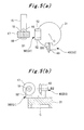
Fig. 5] Fig. 5 includes views showing a state where the dressing device is set at a dresser replacement position and a grinding wheel receiving stage is set at a grinding wheel replacement position. Specifically, Part (a) is a plan view of such state, and Part (b) is a side view of such state. - [
Fig. 6] Fig. 6 is a view showing a state where the dressing device is set at a retreat position and the grinding wheel receiving stage is set at a grinding wheel loading/unloading position. - A gear grinding machine of the present invention is described below in detail by using the drawings.
- As shown in
Figs. 1 and2 , agear grinding machine 1 is provided with abed 11. Acolumn 12 is supported on thisbed 11 to be movable in a horizontal X-axis direction. Moreover, asaddle 13 is supported on thecolumn 12 to be movable up and down in a vertical Z-axis direction. Agrinding wheel head 14 is supported on thissaddle 13 to be movable in an axial direction of a grinding wheel rotation axis B1 (horizontal Y-axis direction). - In addition, a grinding
wheel rotating motor 15 is provided in the grindingwheel head 14. Agrinding wheel shaft 16 is supported by the grindingwheel rotating motor 15 to be rotatable about the grinding wheel rotation axis B1. Further, a threadedgrinding wheel 17 having a helical thread formed in an outer peripheral surface thereof is detachably attached to thegrinding wheel shaft 16. - Note that a grinding wheel attachment structure for attaching the grinding
wheel 17 to the grindingwheel shaft 16 is as follows. First, flange members are fitted into a through hole of thecylindrical grinding wheel 17 from both sides of the through hole, respectively. Then, with the grindingwheel 17 held betweenflange portions 18 of the flange members, thegrinding wheel 17 is fixedly attached to thegrinding wheel shaft 16. - Accordingly, the
grinding wheel 17 can be moved in the X-axis direction, the Y-axis direction, the Z-axis direction, and the axial direction of the grinding wheel rotation axis B1 by driving thecolumn 12, thesaddle 13, and thegrinding wheel head 14. Moreover, the grindingwheel 17 can be rotated about the grinding wheel rotation axis B1 via thegrinding wheel shaft 16 by driving the grindingwheel rotating motor 15. Note that thecolumn 12, thesaddle 13, and the grindingwheel head 14 form grinding wheel moving means for moving thegrinding wheel 17. - Moreover, a cylindrical stationary table 21 is provided in an upper portion of the
bed 11. A shaft-shaped rotary table 22 is supported at a position radially inside the stationary table 21 viabearings - A
table rotating motor 24 is provided between the stationary table 21 and the rotary table 22. Thetable rotating motor 24 is formed of astator 24a fixed on an inner peripheral surface of the stationary table 21 and arotor 24b fixed on an outer peripheral surface of the rotary table 22. Further, a workpiece (gear to be machined) W is attached on a top surface of the rotary table 22 via anattachment jig 25. Accordingly, the workpiece W can be thus rotated together with the rotary table 22 about the workpiece rotation axis C by driving thetable rotating motor 24. - Meanwhile, an
annular groove 21a which is open at an upper portion thereof is formed in a radially-outer portion of the stationary table 21 to extend in a circumferential direction of the stationary table 21. A ring-shaped turn table 31 is housed in theannular groove 21a with abearing 32 in between to be turnable about the workpiece rotation axis C. Specifically, the turn table 31 is disposed coaxially with the stationary table 21 and the rotary table 31. - Moreover, as shown in
Fig. 3 , aturning gear 31a is formed in an outer peripheral surface of the turn table 31 to extend in a circumferential direction thereof. Furthermore, apositioning gear 31b is formed in a lower portion of an inner peripheral surface of the turn table 31 to extend in a circumferential direction thereof. - A hollow
gear box portion 21b is formed integrally with theannular groove 21a. Thegear box portion 21b extends radially (X-axis direction) outward from the center (workpiece rotation axis C) of the rotary table 21 to the opposite side from thecolumn 12. A table turning motor (table turning means) 33 is provided on an upper portion of thegear box portion 21b at an outer end thereof. A drivingshaft 34 of thetable turning motor 33 is disposed in thegear box portion 21b. Adriving gear 34a is formed in an outer peripheral surface of the drivingshaft 34 to extend in a circumferential direction thereof. - An
intermediate shaft 35 and a drivenshaft 36 are rotatably supported in thegear box portion 21b. Theintermediate shaft 35 is provided with an upperintermediate gear 35a and a lowerintermediate gear 35b, while the drivenshaft 36 is provided with a drivengear 36a. Further, thedriving gear 34a and the lowerintermediate gear 35b mesh with each other, the upperintermediate gear 35a and the drivengear 36a mesh with each other, and the drivengear 36a and theturning gear 31a mesh with each other. - In addition, as shown in
Figs. 1 and3 , a ring-shaped slidingmember 37 and a ring-shaped fixedmember 38 are provided between an inner wall surface of theannular groove 21a (i.e., an outer peripheral surface of the stationary table 21) and an inner peripheral surface of the turn table 31, the slidingmember 37 being arranged above the fixedmember 38. - A recessed
cylinder portion 21c is formed in the inner wall surface of theannular groove 21a. The slidingmember 37 is supported by thecylinder portion 21c to be slidable in the vertical direction. Moreover, hydraulic pressure can be supplied to and released from an upper portion and a lower portion of thecylinder portion 21c. The slidingmember 37 moves downward when the hydraulic pressure is supplied to the upper portion of thecylinder portion 21c and moves upward when the hydraulic pressure is supplied to the lower portion of thecylinder portion 21c. Moreover, apositioning gear 37a is formed in a bottom surface of the slidingmember 37. Meanwhile, the fixedmember 38 is fixed in theannular groove 21a, and apositioning gear 38a is formed in a top surface thereof. - The
positioning gear 37a of the slidingmember 37 can mesh with thepositioning gear 31b of the turn table 31 and thepositioning gear 38a of the fixedmember 38 in the vertical direction. In other words, the positioning gears 31b, 37a, 38a form a gear coupling, and positioning of the turn table 31 in a turning direction thereof is performed by the meshing of these gears. - Hence, the turn table 31 can be rotated about the workpiece rotation axis C via the
gears table turning motor 33. In a state where the slidingmember 37 has slid to the uppermost position, thepositioning gear 37a does not mesh with the positioning gears 31b and 38a, allowing the turn table 31 to turn. Meanwhile, in a state where the slidingmember 37 has slid to the lowermost position, thepositioning gear 37a meshes with the positioning gears 31b and 38a, allowing positioning of the turn table 31 in the turning direction to be performed. - A dressing device (dressing means) 40 and a grinding
wheel receiving stage 50 are provided on a top surface of the turn table 31. Note that the dressingdevice 40 and the grindingwheel receiving stage 50 are disposed respectively at positions shifted from each other by 90° in phase in the circumferential direction of the turn table 31. - The dressing
device 40 is a device for dressing the grindingwheel 17 and is formed of a devicemain body 41 fixed on the top surface of the turn table 31, adresser rotating motor 42 provided on this devicemain body 41, and a disc-shapeddresser 43 detachably attached to thedresser rotating motor 42. Hence, thedresser 43 can be rotated about a horizontal dresser rotation axis B2 by driving thedresser rotating motor 42. - Meanwhile, the grinding
wheel receiving stage 50 is a stage for mounting the grindingwheel 17 and is formed of a receiving stagemain body 51 detachably attached on the top surface of the turn table 31 and a pair of left and right receivingmembers 52 provided respectively on both widthwise sides of the receiving stagemain body 51. Note that the distance between the pair of the left and right receivingmembers 52 are set to be the same as the distance between theflange portions 18 provided in both end portions of thegrinding wheel 17, and top surfaces of these receivingmembers 52 are formed in an arc shape to allow theflange portions 18 to be fitted thereto. - As shown in
Figs. 1 ,2 ,4 , and6 , positioning the turn table 31 by causing the turn table 31 to turn at a predetermined turning angle allows the dressingdevice 40 to be set at any of a dressing position D1, a retreat position D2, and a dresser replacement position D2 and also allows the grindingwheel receiving stage 50 to be set at a grinding wheel replacement position G1 or a grinding wheel loading/unloading position G2. - Here, the dressing position D1 (a state where the turning angle of the turn table 31 is 0°) is a position where the dressing
device 40 faces the grindingwheel 17 attached to thegrinding wheel shaft 16. Setting the dressingdevice 40 at the dressing position D1 allows the grindingwheel 17 to be dressed by thedresser 43. - Moreover, the retreat position D2 (a state where the turning angle of the turn table 31 is 180°) is a position where the dressing
device 40 is farthest away from the dressing position D1, i.e. a position on a side opposite to thecolumn 12 with a rotary table 21 in between. Setting the dressingdevice 40 at the retreat position D2 allows the workpiece W to be ground by the grindingwheel 17. - Furthermore, the dresser replacement position D3 (a state where the turning angle of the turn table 31 is 90°) is an intermediate position between the dressing position D1 and the retreat position D2 and is a position facing a worker. Setting the dressing
device 40 at the dresser replacement position D3 allows the worker to replace thedresser 43. - Meanwhile, the grinding wheel replacement position G1 (the state where the turning angle of the turn table 31 is 90°) is a position where the grinding
wheel receiving stage 50 faces the grindingwheel 17 attached to thegrinding wheel shaft 16. Setting the grindingwheel receiving stage 50 at the grinding wheel replacement position G1 allows replacement of thegrinding wheel 17 in thegrinding wheel head 14. - Moreover, the grinding wheel loading/unloading position G2 (the state where the turning angle of the turn table 31 is 180°) is a position facing the worker. Setting the grinding
wheel receiving stage 50 at the grinding wheel loading/unloading position G2 allows the worker to load and unload (replace) thegrinding wheel 17 onto and from the grindingwheel receiving stage 50. - Next, operations of the
gear grinding machine 1 are described by usingFigs. 4 to 6 . - When the workpiece W is to be ground by the grinding
wheel 17, the grindingwheel 17 is first moved in the X-axis direction, the Y-axis direction, the Z-axis direction, and the axial direction of the grinding wheel rotation axis B1 to stand by at a position above or below the workpiece W attached to theattachment jig 25. - Then, the grinding
wheel 17 is rotated about the grinding wheel rotation axis B1, and the workpiece W is rotated about the workpiece rotation axis C. Thereafter, the grindingwheel 17 is moved in the Z-axis direction and is made to mesh with the workpiece W. Tooth surfaces of the workpiece W are thus ground by edge surfaces of thegrinding wheel 17. - Note that, in the grinding described above, as shown in
Fig. 6 , the turn table 31 is turned to set the dressingdevice 40 at the retreat position D2 in advance. Meanwhile, as illustrated by two-dot chain lines of Parts (a) and (b) ofFig. 4 , the grindingwheel receiving stage 50 is removed from the turn table 31 in advance. - When a certain number of workpieces W are ground by using the
grinding wheel 17, the edge surfaces thereof wears and the sharpness thereof deteriorates. Hence, the grindingwheel 17 needs to be regularly dressed by thedresser 43. - When the
grinding wheel 17 is to be dressed by thedresser 43, as shown in Parts (a) and 4 (b) ofFig. 4 , the turn table 31 is turned with the workpiece W attached to theattachment jig 25, and the dressingdevice 40 is thereby moved from the retreat position D2 to the dressing position D1. - Next, the
dresser 43 is rotated about the dresser rotation axis B2. Thereafter, the grindingwheel 17 is moved in the X-axis direction, the Y-axis direction, the Z-axis direction, and the axial direction of the grinding wheel rotation axis B1 and is made to mesh with thedresser 43 set at the dressing position D1. - Then, from this meshing state, the grinding
wheel 17 is rotated about the grinding wheel rotation axis B1 and is moved in the Y-axis direction and the axial direction of the grinding wheel rotation axis B1. The edge surfaces of thegrinding wheel 17 are thus dressed by edge surfaces of thedresser 43. - Moreover, when the
dresser 43 wears and is to be replaced with thenew dresser 43 or when thedresser 43 is to be replaced with thedresser 43 of a different type depending on an edge shape of thegrinding wheel 17, as shown in Parts (a) and (b) ofFig. 5 , the turn table 31 is turned with the workpiece W attached to theattachment jig 25 to move thedressing device 40 from the dressing position D1 or the retreat position D2 to the dresser replacement position D3. - Then, the worker performs a replacement work of the
dresser 43 for the dressingdevice 40 set at the dresser replacement position D3. - Then, as shown in Parts (a) and (b) of
Fig. 4 , the turn table 31 is turned so that the dressingdevice 40 for which the dresser replacement work has been completed is moved from the dresser replacement position D3 to the dressing position D1. Thereafter, the grindingwheel 17 is subsequently dressed by the replaceddresser 43. - Instead, as shown in
Fig. 6 , the turn table 31 is turned so that the dressingdevice 40 for which the dresser replacement work has been completed is moved from the dresser replacement position D3 to the retreat position D2. Thereafter, the replaceddresser 43 is made to stand by for the next dressing. - Furthermore, when the grinding
wheel 17 wears and is to be replaced with thenew grinding wheel 17 or when the grindingwheel 17 is to be replaced with the grindingwheel 17 of a different type depending on a tooth profile of the workpiece W, the turn table 31 is first turned with the workpiece W attached to theattachment jig 25, and the worker attaches the empty grindingwheel receiving stage 50 to a predetermined position of the turn table 31 at the grinding wheel loading/unloading position G2. - Then, as shown in Part (a) of
Fig. 5 , the turn table 31 is turned so that the empty grindingwheel receiving stage 50 is moved from the grinding wheel loading/unloading position G2 to the grinding wheel replacement position G1. - Next, the grinding
wheel 17 is moved in the X-axis direction, the Y-axis direction, the Z-axis direction and the axial direction of the grinding wheel rotation axis B1 to be mounted on the empty grindingwheel receiving stage 50 set at the grinding wheel replacement position G1. At this time, theflange portions 18 of thegrinding wheel 17 are fitted to the receivingmembers 52 of the grindingwheel receiving stage 50. - Subsequently, as shown in Part (b) of
Fig. 5 , thegrinding wheel head 14 is moved in the X-axis direction, the Y-axis direction, the Z-axis direction, and the axial direction of the grinding wheel rotation axis B1 with the grindingwheel 17 mounted on the grindingwheel receiving stage 50 to pull thegrinding wheel shaft 16 out from the grindingwheel 17. Hence, the grindingwheel 17 is separated from thegrinding wheel head 14. - Then, as shown in
Fig. 6 , the turn table 31 is turned to move the grindingwheel receiving stage 50 having the grindingwheel 17 mounted thereon from the grinding wheel replacement position G1 to the grinding wheel loading/unloading position G2. - Next, the worker performs the loading/unloading (replacement) work of the
grinding wheel 17 to and from the grindingwheel receiving stage 50 set at the grinding wheel loading/unloading position G2. Specifically, the mountedgrinding wheel 17 is unloaded from the grindingwheel receiving stage 50 and thenew grinding wheel 17 is loaded onto the empty grindingwheel receiving stage 50. - Then, as shown in Part (b) of
Fig. 5 , the turn table 31 is turned to move the grindingwheel receiving stage 50 having thenew grinding wheel 17 mounted thereon from the grinding wheel loading/unloading position G2 to the grinding wheel replacement position G1. - Subsequently, as shown in Part (a) of
Fig. 5 , thegrinding wheel head 14 is moved in the X-axis direction, the Y-axis direction, the Z-axis direction, and the axial direction of the grinding wheel rotation axis B1 with the grindingwheel 17 mounted on the grindingwheel receiving stage 50 to fit thegrinding wheel shaft 16 into the grindingwheel 17. Thenew grinding wheel 17 is thus attached to thegrinding wheel shaft 16, and the replacement of thegrinding wheel 17 is completed. - Then, as shown in
Fig. 6 , the turn table 31 is turned to move the empty grindingwheel receiving stage 50 from the grinding wheel replacement position G1 to the grinding wheel loading/unloading position G2. Thereafter, the grindingwheel receiving stage 50 is detached by the worker. - In the embodiment described above, the gear grinding machine of the present invention is applied to the
gear grinding machine 1 employing a generating grinding method using the threadedgrinding wheel 17. However, the gear grinding machine of the present invention may be applied to a gear grinding machine employing a profile grinding method using a disc-shaped grinding wheel. - In the gear grinding machine of the present invention, the turn table 31 is turned about the workpiece rotation axis C at a position radially outside the rotary table 22 which holds the workpiece W and which is rotated about the workpiece rotation axis C, and the dressing
device 40 is thereby moved between the dressing position D1 and the retreat position D2. Accordingly, a contact between the dressingdevice 40 and the workpiece W can be prevented. This allows the grindingwheel 17 to be dressed by thedresser 43 with the workpiece W attached to the rotary table 22, regardless of the size of the workpiece W. - Moreover, turning the turn table 31 to move the
dressing device 40 to the dresser replacement position D3 allows thedresser 43 to be easily replaced with the workpiece W attached to the rotary table 22. - In addition, the
annular groove 21a is provided in the radially-outer portion of the stationary table 21 which rotatably supports the rotary table 22, and the turn table 31 is turnably housed in theannular groove 21a. This allows the turn table 31 to be stably turned. - Furthermore, the turn table 31 is turned about the workpiece rotation axis C to move the grinding
wheel receiving stage 50 between the grinding wheel replacement position G1 and the grinding wheel loading/unloading position G2. Accordingly, a contact of the workpiece W with the grindingwheel receiving stage 50 and thegrinding wheel 17 mounted thereon is prevented. This allows the grindingwheel 17 to be easily replaced with the workpiece W attached to the rotary table 22, regardless of the size of the workpiece W. - The present invention can be applied to a gear grinding machine designed to save space.
Claims (4)
- A gear grinding machine for performing grinding on a gear to be machined by rotating the gear to be machined and a grinding wheel in mesh with each other, characterized in that the gear grinding machine comprises:a rotary table configured to hold the gear to be machined and to rotate about a workpiece rotation axis;grinding wheel moving means for rotatably supporting the grinding wheel and moving the grinding wheel relative to the workpiece rotation axis;a ring-shaped turn table disposed coaxially with the rotary table at a position radially outside the rotary table, and supported turnably about the workpiece rotation axis;dressing means provided on the turn table and having a dresser capable of dressing the grinding wheel; andtable turning means for turning the turn table about the workpiece rotation axis in such a way that the dressing means moves between a dressing position where the dressing means is capable of dressing the grinding wheel supported by the grinding wheel moving means and a retreat position where the dressing means is retreated from the dressing position during the grinding.
- The gear grinding machine according to claim 1, characterized in that the table turning means turns the turn table about the workpiece rotation axis in such a way that the dressing means moves to a dresser replacement position where replacement of the dresser is possible.
- The gear grinding machine according to claim 1, characterized in that the gear grinding machine further comprises:a stationary table provided radially outside the rotary table and configured to support the rotary table with the rotary table being rotatable about the workpiece axis; andan annular groove provided in an radially-outer portion of the stationary table and configured to house the turn table with the turn table being turnable.
- The gear grinding machine according to claim 1, characterized in that
the gear grinding machine further comprises a grinding wheel receiving stage provided on the turn table and configured in such a way that the grinding wheel is mounted on the gear grinding wheel receiving stage, and
the table turning means turns the turn table about the workpiece rotation axis in such a way that the grinding wheel receiving stage moves between a grinding wheel replacement position where replacement of the grinding wheel in the grinding wheel moving means is possible and a grinding wheel loading/unloading position where loading and unloading of the grinding wheel to and from the grinding wheel receiving stage is possible.
Applications Claiming Priority (2)
| Application Number | Priority Date | Filing Date | Title |
|---|---|---|---|
| JP2010199455A JP5285672B2 (en) | 2010-09-07 | 2010-09-07 | Gear grinding machine |
| PCT/JP2011/069138 WO2012032941A1 (en) | 2010-09-07 | 2011-08-25 | Gear grinding machine |
Publications (3)
| Publication Number | Publication Date |
|---|---|
| EP2614923A1 true EP2614923A1 (en) | 2013-07-17 |
| EP2614923A4 EP2614923A4 (en) | 2017-10-11 |
| EP2614923B1 EP2614923B1 (en) | 2019-04-24 |
Family
ID=45810544
Family Applications (1)
| Application Number | Title | Priority Date | Filing Date |
|---|---|---|---|
| EP11823420.2A Active EP2614923B1 (en) | 2010-09-07 | 2011-08-25 | Gear grinding machine |
Country Status (7)
| Country | Link |
|---|---|
| US (1) | US9511477B2 (en) |
| EP (1) | EP2614923B1 (en) |
| JP (1) | JP5285672B2 (en) |
| CN (1) | CN103079763B (en) |
| BR (1) | BR112013004966A2 (en) |
| TW (1) | TWI450781B (en) |
| WO (1) | WO2012032941A1 (en) |
Cited By (2)
| Publication number | Priority date | Publication date | Assignee | Title |
|---|---|---|---|---|
| CN106735618A (en) * | 2016-12-01 | 2017-05-31 | 鞍山海咯尔装备制造股份有限公司 | Mending teeth of gear measuring instrument |
| WO2019120831A1 (en) * | 2017-12-22 | 2019-06-27 | Gleason-Pfauter Maschinenfabrik Gmbh | Method for machining toothings, as well as toothing machine and control program for same |
Families Citing this family (11)
| Publication number | Priority date | Publication date | Assignee | Title |
|---|---|---|---|---|
| EP2732895B1 (en) * | 2012-11-14 | 2015-10-21 | Burri Werkzeugmaschinen GmbH & Co. KG | Machine tool for manufacturing profiles |
| JP6406100B2 (en) * | 2015-03-31 | 2018-10-17 | アイシン・エィ・ダブリュ株式会社 | How to replace a grindstone on a rotary machine |
| JP6453199B2 (en) * | 2015-10-16 | 2019-01-16 | 光洋機械工業株式会社 | Centerless grinding machine |
| CN108637807B (en) * | 2018-05-11 | 2020-07-07 | 广西富荔科技有限公司 | Setting device is used in processing of two-sided profile of tooth blade |
| JP7043346B2 (en) * | 2018-05-18 | 2022-03-29 | 株式会社ディスコ | Cutting equipment |
| JP7152745B2 (en) * | 2018-06-13 | 2022-10-13 | 株式会社 神崎高級工機製作所 | Gear processing equipment |
| CN109262414B (en) * | 2018-09-19 | 2023-07-04 | 赛迈科先进材料股份有限公司 | Processing equipment for ultrathin graphite sample |
| KR102205168B1 (en) * | 2020-02-04 | 2021-01-20 | 케이피엠 주식회사 | Portable flange facer |
| WO2022021575A1 (en) * | 2020-07-29 | 2022-02-03 | 湖南中大创远数控装备有限公司 | Gear grinding machine |
| JP7768715B2 (en) * | 2021-09-30 | 2025-11-12 | 株式会社ディスコ | cutting equipment |
| CN120516098B (en) * | 2025-07-28 | 2025-10-28 | 江苏亿鑫齿轮制造有限公司 | Gear processing and grinding device |
Family Cites Families (15)
| Publication number | Priority date | Publication date | Assignee | Title |
|---|---|---|---|---|
| US1585706A (en) * | 1922-10-10 | 1926-05-25 | Einar A Hanson | Truing device for grinding wheels |
| DE19625370C1 (en) | 1996-06-25 | 1997-04-30 | Reishauer Ag | Grinding machine for continuous roller grinding of spur wheel gears |
| DE19910746B4 (en) * | 1999-03-11 | 2007-02-08 | Reishauer Ag | Apparatus and method for profiling grinding wheels |
| US6379229B1 (en) * | 1999-05-17 | 2002-04-30 | Ebara Corporation | Polishing apparatus |
| DE10132695B4 (en) * | 2001-07-05 | 2009-02-05 | Reishauer Ag | Dressing grinding tools for gear grinding |
| CN1173804C (en) * | 2002-12-03 | 2004-11-03 | 汕头大学 | Grinding wheel dresser |
| JP4563017B2 (en) * | 2003-10-07 | 2010-10-13 | 三菱重工業株式会社 | Gear grinding machine and dressing method for gear grinding machine wheel |
| US7927048B2 (en) * | 2004-09-25 | 2011-04-19 | Klingelnberg Gmbh | Device and method for machining gear wheels in an indexing method with a reduced indexing time |
| CN100361783C (en) * | 2005-04-07 | 2008-01-16 | 上海第三机床厂 | Digital Curve Grinder |
| CN1803358A (en) * | 2006-01-10 | 2006-07-19 | 潘旭华 | Special machine tool for grinding teeth of grinding wheel |
| JP4648219B2 (en) * | 2006-02-28 | 2011-03-09 | 三菱重工業株式会社 | Gear grinding machine |
| DE102007022603A1 (en) * | 2007-05-12 | 2008-11-13 | Kapp Gmbh | Hard finishing machine |
| DE102008010301A1 (en) * | 2008-02-21 | 2009-09-03 | Liebherr-Verzahntechnik Gmbh | Method for operating a gear grinding machine |
| JP5148400B2 (en) * | 2008-07-25 | 2013-02-20 | 三菱重工業株式会社 | Gear grinding machine |
| JP5285416B2 (en) * | 2008-12-22 | 2013-09-11 | 三菱重工業株式会社 | Internal gear grinding machine and barrel threading tool dressing method |
-
2010
- 2010-09-07 JP JP2010199455A patent/JP5285672B2/en active Active
-
2011
- 2011-08-19 TW TW100129810A patent/TWI450781B/en active
- 2011-08-25 CN CN201180042301.5A patent/CN103079763B/en active Active
- 2011-08-25 EP EP11823420.2A patent/EP2614923B1/en active Active
- 2011-08-25 BR BR112013004966A patent/BR112013004966A2/en not_active IP Right Cessation
- 2011-08-25 WO PCT/JP2011/069138 patent/WO2012032941A1/en not_active Ceased
- 2011-08-25 US US13/820,203 patent/US9511477B2/en active Active
Cited By (2)
| Publication number | Priority date | Publication date | Assignee | Title |
|---|---|---|---|---|
| CN106735618A (en) * | 2016-12-01 | 2017-05-31 | 鞍山海咯尔装备制造股份有限公司 | Mending teeth of gear measuring instrument |
| WO2019120831A1 (en) * | 2017-12-22 | 2019-06-27 | Gleason-Pfauter Maschinenfabrik Gmbh | Method for machining toothings, as well as toothing machine and control program for same |
Also Published As
| Publication number | Publication date |
|---|---|
| US9511477B2 (en) | 2016-12-06 |
| JP2012055986A (en) | 2012-03-22 |
| US20130244549A1 (en) | 2013-09-19 |
| EP2614923B1 (en) | 2019-04-24 |
| EP2614923A4 (en) | 2017-10-11 |
| CN103079763A (en) | 2013-05-01 |
| BR112013004966A2 (en) | 2016-08-16 |
| WO2012032941A1 (en) | 2012-03-15 |
| TWI450781B (en) | 2014-09-01 |
| JP5285672B2 (en) | 2013-09-11 |
| CN103079763B (en) | 2015-04-01 |
| TW201219134A (en) | 2012-05-16 |
Similar Documents
| Publication | Publication Date | Title |
|---|---|---|
| EP2614923B1 (en) | Gear grinding machine | |
| JP5308388B2 (en) | Gear processing machine | |
| US8882569B2 (en) | Gear grinding machine | |
| JP6004890B2 (en) | Combined processing grinder and processing method using the same | |
| JP5125406B2 (en) | Swivel device and cylindrical grinder provided with the same | |
| JP2002066850A (en) | Machining center and tool changing method | |
| JP5968000B2 (en) | Gear processing machine | |
| JP4563017B2 (en) | Gear grinding machine and dressing method for gear grinding machine wheel | |
| JP5148400B2 (en) | Gear grinding machine | |
| JP5125391B2 (en) | Swivel device and cylindrical grinder provided with the same | |
| JP6540198B2 (en) | Compound grinding machine and compound grinding method | |
| JP5331072B2 (en) | Gear grinding machine | |
| TWI402138B (en) | Gear grinding machine | |
| CN215659329U (en) | Centerless grinding machine capable of being rapidly disassembled | |
| JP5881446B2 (en) | Gear grinding machine | |
| JP6406100B2 (en) | How to replace a grindstone on a rotary machine | |
| JP5549391B2 (en) | Grinder | |
| JP2024055431A (en) | Gear grinding machine and dressing method | |
| JP2017019045A (en) | Complex processor and processing method therefor |
Legal Events
| Date | Code | Title | Description |
|---|---|---|---|
| PUAI | Public reference made under article 153(3) epc to a published international application that has entered the european phase |
Free format text: ORIGINAL CODE: 0009012 |
|
| 17P | Request for examination filed |
Effective date: 20130307 |
|
| AK | Designated contracting states |
Kind code of ref document: A1 Designated state(s): AL AT BE BG CH CY CZ DE DK EE ES FI FR GB GR HR HU IE IS IT LI LT LU LV MC MK MT NL NO PL PT RO RS SE SI SK SM TR |
|
| DAX | Request for extension of the european patent (deleted) | ||
| RAP1 | Party data changed (applicant data changed or rights of an application transferred) |
Owner name: MITSUBISHI HEAVY INDUSTRIES MACHINE TOOL CO., LTD. |
|
| RA4 | Supplementary search report drawn up and despatched (corrected) |
Effective date: 20170911 |
|
| RIC1 | Information provided on ipc code assigned before grant |
Ipc: B23F 5/04 20060101ALI20170905BHEP Ipc: B24B 53/075 20060101AFI20170905BHEP Ipc: B23F 23/12 20060101ALI20170905BHEP |
|
| RIC1 | Information provided on ipc code assigned before grant |
Ipc: B23F 5/04 20060101ALI20180806BHEP Ipc: B24B 53/075 20060101AFI20180806BHEP Ipc: B23F 23/12 20060101ALI20180806BHEP |
|
| GRAP | Despatch of communication of intention to grant a patent |
Free format text: ORIGINAL CODE: EPIDOSNIGR1 |
|
| STAA | Information on the status of an ep patent application or granted ep patent |
Free format text: STATUS: GRANT OF PATENT IS INTENDED |
|
| INTG | Intention to grant announced |
Effective date: 20180914 |
|
| GRAJ | Information related to disapproval of communication of intention to grant by the applicant or resumption of examination proceedings by the epo deleted |
Free format text: ORIGINAL CODE: EPIDOSDIGR1 |
|
| STAA | Information on the status of an ep patent application or granted ep patent |
Free format text: STATUS: REQUEST FOR EXAMINATION WAS MADE |
|
| INTC | Intention to grant announced (deleted) | ||
| GRAR | Information related to intention to grant a patent recorded |
Free format text: ORIGINAL CODE: EPIDOSNIGR71 |
|
| GRAS | Grant fee paid |
Free format text: ORIGINAL CODE: EPIDOSNIGR3 |
|
| STAA | Information on the status of an ep patent application or granted ep patent |
Free format text: STATUS: GRANT OF PATENT IS INTENDED |
|
| GRAA | (expected) grant |
Free format text: ORIGINAL CODE: 0009210 |
|
| STAA | Information on the status of an ep patent application or granted ep patent |
Free format text: STATUS: THE PATENT HAS BEEN GRANTED |
|
| AK | Designated contracting states |
Kind code of ref document: B1 Designated state(s): AL AT BE BG CH CY CZ DE DK EE ES FI FR GB GR HR HU IE IS IT LI LT LU LV MC MK MT NL NO PL PT RO RS SE SI SK SM TR |
|
| INTG | Intention to grant announced |
Effective date: 20190318 |
|
| REG | Reference to a national code |
Ref country code: GB Ref legal event code: FG4D |
|
| REG | Reference to a national code |
Ref country code: CH Ref legal event code: EP |
|
| REG | Reference to a national code |
Ref country code: AT Ref legal event code: REF Ref document number: 1123566 Country of ref document: AT Kind code of ref document: T Effective date: 20190515 Ref country code: IE Ref legal event code: FG4D |
|
| REG | Reference to a national code |
Ref country code: DE Ref legal event code: R096 Ref document number: 602011058379 Country of ref document: DE |
|
| REG | Reference to a national code |
Ref country code: NL Ref legal event code: MP Effective date: 20190424 |
|
| REG | Reference to a national code |
Ref country code: LT Ref legal event code: MG4D |
|
| PG25 | Lapsed in a contracting state [announced via postgrant information from national office to epo] |
Ref country code: NL Free format text: LAPSE BECAUSE OF FAILURE TO SUBMIT A TRANSLATION OF THE DESCRIPTION OR TO PAY THE FEE WITHIN THE PRESCRIBED TIME-LIMIT Effective date: 20190424 |
|
| PG25 | Lapsed in a contracting state [announced via postgrant information from national office to epo] |
Ref country code: LT Free format text: LAPSE BECAUSE OF FAILURE TO SUBMIT A TRANSLATION OF THE DESCRIPTION OR TO PAY THE FEE WITHIN THE PRESCRIBED TIME-LIMIT Effective date: 20190424 Ref country code: SE Free format text: LAPSE BECAUSE OF FAILURE TO SUBMIT A TRANSLATION OF THE DESCRIPTION OR TO PAY THE FEE WITHIN THE PRESCRIBED TIME-LIMIT Effective date: 20190424 Ref country code: ES Free format text: LAPSE BECAUSE OF FAILURE TO SUBMIT A TRANSLATION OF THE DESCRIPTION OR TO PAY THE FEE WITHIN THE PRESCRIBED TIME-LIMIT Effective date: 20190424 Ref country code: HR Free format text: LAPSE BECAUSE OF FAILURE TO SUBMIT A TRANSLATION OF THE DESCRIPTION OR TO PAY THE FEE WITHIN THE PRESCRIBED TIME-LIMIT Effective date: 20190424 Ref country code: NO Free format text: LAPSE BECAUSE OF FAILURE TO SUBMIT A TRANSLATION OF THE DESCRIPTION OR TO PAY THE FEE WITHIN THE PRESCRIBED TIME-LIMIT Effective date: 20190724 Ref country code: FI Free format text: LAPSE BECAUSE OF FAILURE TO SUBMIT A TRANSLATION OF THE DESCRIPTION OR TO PAY THE FEE WITHIN THE PRESCRIBED TIME-LIMIT Effective date: 20190424 Ref country code: PT Free format text: LAPSE BECAUSE OF FAILURE TO SUBMIT A TRANSLATION OF THE DESCRIPTION OR TO PAY THE FEE WITHIN THE PRESCRIBED TIME-LIMIT Effective date: 20190824 Ref country code: AL Free format text: LAPSE BECAUSE OF FAILURE TO SUBMIT A TRANSLATION OF THE DESCRIPTION OR TO PAY THE FEE WITHIN THE PRESCRIBED TIME-LIMIT Effective date: 20190424 |
|
| PG25 | Lapsed in a contracting state [announced via postgrant information from national office to epo] |
Ref country code: LV Free format text: LAPSE BECAUSE OF FAILURE TO SUBMIT A TRANSLATION OF THE DESCRIPTION OR TO PAY THE FEE WITHIN THE PRESCRIBED TIME-LIMIT Effective date: 20190424 Ref country code: GR Free format text: LAPSE BECAUSE OF FAILURE TO SUBMIT A TRANSLATION OF THE DESCRIPTION OR TO PAY THE FEE WITHIN THE PRESCRIBED TIME-LIMIT Effective date: 20190725 Ref country code: PL Free format text: LAPSE BECAUSE OF FAILURE TO SUBMIT A TRANSLATION OF THE DESCRIPTION OR TO PAY THE FEE WITHIN THE PRESCRIBED TIME-LIMIT Effective date: 20190424 Ref country code: RS Free format text: LAPSE BECAUSE OF FAILURE TO SUBMIT A TRANSLATION OF THE DESCRIPTION OR TO PAY THE FEE WITHIN THE PRESCRIBED TIME-LIMIT Effective date: 20190424 Ref country code: BG Free format text: LAPSE BECAUSE OF FAILURE TO SUBMIT A TRANSLATION OF THE DESCRIPTION OR TO PAY THE FEE WITHIN THE PRESCRIBED TIME-LIMIT Effective date: 20190724 |
|
| REG | Reference to a national code |
Ref country code: AT Ref legal event code: MK05 Ref document number: 1123566 Country of ref document: AT Kind code of ref document: T Effective date: 20190424 |
|
| PG25 | Lapsed in a contracting state [announced via postgrant information from national office to epo] |
Ref country code: IS Free format text: LAPSE BECAUSE OF FAILURE TO SUBMIT A TRANSLATION OF THE DESCRIPTION OR TO PAY THE FEE WITHIN THE PRESCRIBED TIME-LIMIT Effective date: 20190824 |
|
| REG | Reference to a national code |
Ref country code: DE Ref legal event code: R097 Ref document number: 602011058379 Country of ref document: DE |
|
| PG25 | Lapsed in a contracting state [announced via postgrant information from national office to epo] |
Ref country code: RO Free format text: LAPSE BECAUSE OF FAILURE TO SUBMIT A TRANSLATION OF THE DESCRIPTION OR TO PAY THE FEE WITHIN THE PRESCRIBED TIME-LIMIT Effective date: 20190424 Ref country code: CZ Free format text: LAPSE BECAUSE OF FAILURE TO SUBMIT A TRANSLATION OF THE DESCRIPTION OR TO PAY THE FEE WITHIN THE PRESCRIBED TIME-LIMIT Effective date: 20190424 Ref country code: SK Free format text: LAPSE BECAUSE OF FAILURE TO SUBMIT A TRANSLATION OF THE DESCRIPTION OR TO PAY THE FEE WITHIN THE PRESCRIBED TIME-LIMIT Effective date: 20190424 Ref country code: AT Free format text: LAPSE BECAUSE OF FAILURE TO SUBMIT A TRANSLATION OF THE DESCRIPTION OR TO PAY THE FEE WITHIN THE PRESCRIBED TIME-LIMIT Effective date: 20190424 Ref country code: EE Free format text: LAPSE BECAUSE OF FAILURE TO SUBMIT A TRANSLATION OF THE DESCRIPTION OR TO PAY THE FEE WITHIN THE PRESCRIBED TIME-LIMIT Effective date: 20190424 Ref country code: DK Free format text: LAPSE BECAUSE OF FAILURE TO SUBMIT A TRANSLATION OF THE DESCRIPTION OR TO PAY THE FEE WITHIN THE PRESCRIBED TIME-LIMIT Effective date: 20190424 |
|
| PG25 | Lapsed in a contracting state [announced via postgrant information from national office to epo] |
Ref country code: SM Free format text: LAPSE BECAUSE OF FAILURE TO SUBMIT A TRANSLATION OF THE DESCRIPTION OR TO PAY THE FEE WITHIN THE PRESCRIBED TIME-LIMIT Effective date: 20190424 |
|
| PLBE | No opposition filed within time limit |
Free format text: ORIGINAL CODE: 0009261 |
|
| STAA | Information on the status of an ep patent application or granted ep patent |
Free format text: STATUS: NO OPPOSITION FILED WITHIN TIME LIMIT |
|
| PG25 | Lapsed in a contracting state [announced via postgrant information from national office to epo] |
Ref country code: TR Free format text: LAPSE BECAUSE OF FAILURE TO SUBMIT A TRANSLATION OF THE DESCRIPTION OR TO PAY THE FEE WITHIN THE PRESCRIBED TIME-LIMIT Effective date: 20190424 |
|
| 26N | No opposition filed |
Effective date: 20200127 |
|
| GBPC | Gb: european patent ceased through non-payment of renewal fee |
Effective date: 20190825 |
|
| PG25 | Lapsed in a contracting state [announced via postgrant information from national office to epo] |
Ref country code: SI Free format text: LAPSE BECAUSE OF FAILURE TO SUBMIT A TRANSLATION OF THE DESCRIPTION OR TO PAY THE FEE WITHIN THE PRESCRIBED TIME-LIMIT Effective date: 20190424 Ref country code: MC Free format text: LAPSE BECAUSE OF FAILURE TO SUBMIT A TRANSLATION OF THE DESCRIPTION OR TO PAY THE FEE WITHIN THE PRESCRIBED TIME-LIMIT Effective date: 20190424 Ref country code: CH Free format text: LAPSE BECAUSE OF NON-PAYMENT OF DUE FEES Effective date: 20190831 Ref country code: LI Free format text: LAPSE BECAUSE OF NON-PAYMENT OF DUE FEES Effective date: 20190831 Ref country code: LU Free format text: LAPSE BECAUSE OF NON-PAYMENT OF DUE FEES Effective date: 20190825 |
|
| REG | Reference to a national code |
Ref country code: BE Ref legal event code: MM Effective date: 20190831 |
|
| PG25 | Lapsed in a contracting state [announced via postgrant information from national office to epo] |
Ref country code: IE Free format text: LAPSE BECAUSE OF NON-PAYMENT OF DUE FEES Effective date: 20190825 Ref country code: FR Free format text: LAPSE BECAUSE OF NON-PAYMENT OF DUE FEES Effective date: 20190831 |
|
| PG25 | Lapsed in a contracting state [announced via postgrant information from national office to epo] |
Ref country code: BE Free format text: LAPSE BECAUSE OF NON-PAYMENT OF DUE FEES Effective date: 20190831 Ref country code: GB Free format text: LAPSE BECAUSE OF NON-PAYMENT OF DUE FEES Effective date: 20190825 |
|
| PG25 | Lapsed in a contracting state [announced via postgrant information from national office to epo] |
Ref country code: CY Free format text: LAPSE BECAUSE OF FAILURE TO SUBMIT A TRANSLATION OF THE DESCRIPTION OR TO PAY THE FEE WITHIN THE PRESCRIBED TIME-LIMIT Effective date: 20190424 |
|
| PG25 | Lapsed in a contracting state [announced via postgrant information from national office to epo] |
Ref country code: HU Free format text: LAPSE BECAUSE OF FAILURE TO SUBMIT A TRANSLATION OF THE DESCRIPTION OR TO PAY THE FEE WITHIN THE PRESCRIBED TIME-LIMIT; INVALID AB INITIO Effective date: 20110825 Ref country code: MT Free format text: LAPSE BECAUSE OF FAILURE TO SUBMIT A TRANSLATION OF THE DESCRIPTION OR TO PAY THE FEE WITHIN THE PRESCRIBED TIME-LIMIT Effective date: 20190424 |
|
| PG25 | Lapsed in a contracting state [announced via postgrant information from national office to epo] |
Ref country code: MK Free format text: LAPSE BECAUSE OF FAILURE TO SUBMIT A TRANSLATION OF THE DESCRIPTION OR TO PAY THE FEE WITHIN THE PRESCRIBED TIME-LIMIT Effective date: 20190424 |
|
| P01 | Opt-out of the competence of the unified patent court (upc) registered |
Effective date: 20230519 |
|
| PGFP | Annual fee paid to national office [announced via postgrant information from national office to epo] |
Ref country code: DE Payment date: 20250819 Year of fee payment: 15 |
|
| PGFP | Annual fee paid to national office [announced via postgrant information from national office to epo] |
Ref country code: IT Payment date: 20250829 Year of fee payment: 15 |