EP2614914A1 - A fuel nozzle and process of fabricating a fuel nozzle - Google Patents
A fuel nozzle and process of fabricating a fuel nozzle Download PDFInfo
- Publication number
- EP2614914A1 EP2614914A1 EP13150543.0A EP13150543A EP2614914A1 EP 2614914 A1 EP2614914 A1 EP 2614914A1 EP 13150543 A EP13150543 A EP 13150543A EP 2614914 A1 EP2614914 A1 EP 2614914A1
- Authority
- EP
- European Patent Office
- Prior art keywords
- fuel nozzle
- nozzle insert
- end cover
- welding
- insert portion
- Prior art date
- Legal status (The legal status is an assumption and is not a legal conclusion. Google has not performed a legal analysis and makes no representation as to the accuracy of the status listed.)
- Granted
Links
Images

Classifications
-
- B—PERFORMING OPERATIONS; TRANSPORTING
- B23—MACHINE TOOLS; METAL-WORKING NOT OTHERWISE PROVIDED FOR
- B23K—SOLDERING OR UNSOLDERING; WELDING; CLADDING OR PLATING BY SOLDERING OR WELDING; CUTTING BY APPLYING HEAT LOCALLY, e.g. FLAME CUTTING; WORKING BY LASER BEAM
- B23K15/00—Electron-beam welding or cutting
- B23K15/0006—Electron-beam welding or cutting specially adapted for particular articles or work
-
- B—PERFORMING OPERATIONS; TRANSPORTING
- B23—MACHINE TOOLS; METAL-WORKING NOT OTHERWISE PROVIDED FOR
- B23K—SOLDERING OR UNSOLDERING; WELDING; CLADDING OR PLATING BY SOLDERING OR WELDING; CUTTING BY APPLYING HEAT LOCALLY, e.g. FLAME CUTTING; WORKING BY LASER BEAM
- B23K13/00—Welding by high-frequency current heating
-
- B—PERFORMING OPERATIONS; TRANSPORTING
- B23—MACHINE TOOLS; METAL-WORKING NOT OTHERWISE PROVIDED FOR
- B23K—SOLDERING OR UNSOLDERING; WELDING; CLADDING OR PLATING BY SOLDERING OR WELDING; CUTTING BY APPLYING HEAT LOCALLY, e.g. FLAME CUTTING; WORKING BY LASER BEAM
- B23K20/00—Non-electric welding by applying impact or other pressure, with or without the application of heat, e.g. cladding or plating
- B23K20/06—Non-electric welding by applying impact or other pressure, with or without the application of heat, e.g. cladding or plating by means of high energy impulses, e.g. magnetic energy
-
- B—PERFORMING OPERATIONS; TRANSPORTING
- B23—MACHINE TOOLS; METAL-WORKING NOT OTHERWISE PROVIDED FOR
- B23K—SOLDERING OR UNSOLDERING; WELDING; CLADDING OR PLATING BY SOLDERING OR WELDING; CUTTING BY APPLYING HEAT LOCALLY, e.g. FLAME CUTTING; WORKING BY LASER BEAM
- B23K20/00—Non-electric welding by applying impact or other pressure, with or without the application of heat, e.g. cladding or plating
- B23K20/06—Non-electric welding by applying impact or other pressure, with or without the application of heat, e.g. cladding or plating by means of high energy impulses, e.g. magnetic energy
- B23K20/08—Explosive welding
-
- B—PERFORMING OPERATIONS; TRANSPORTING
- B23—MACHINE TOOLS; METAL-WORKING NOT OTHERWISE PROVIDED FOR
- B23K—SOLDERING OR UNSOLDERING; WELDING; CLADDING OR PLATING BY SOLDERING OR WELDING; CUTTING BY APPLYING HEAT LOCALLY, e.g. FLAME CUTTING; WORKING BY LASER BEAM
- B23K20/00—Non-electric welding by applying impact or other pressure, with or without the application of heat, e.g. cladding or plating
- B23K20/12—Non-electric welding by applying impact or other pressure, with or without the application of heat, e.g. cladding or plating the heat being generated by friction; Friction welding
- B23K20/122—Non-electric welding by applying impact or other pressure, with or without the application of heat, e.g. cladding or plating the heat being generated by friction; Friction welding using a non-consumable tool, e.g. friction stir welding
-
- B—PERFORMING OPERATIONS; TRANSPORTING
- B23—MACHINE TOOLS; METAL-WORKING NOT OTHERWISE PROVIDED FOR
- B23K—SOLDERING OR UNSOLDERING; WELDING; CLADDING OR PLATING BY SOLDERING OR WELDING; CUTTING BY APPLYING HEAT LOCALLY, e.g. FLAME CUTTING; WORKING BY LASER BEAM
- B23K26/00—Working by laser beam, e.g. welding, cutting or boring
- B23K26/20—Bonding
- B23K26/21—Bonding by welding
-
- B—PERFORMING OPERATIONS; TRANSPORTING
- B23—MACHINE TOOLS; METAL-WORKING NOT OTHERWISE PROVIDED FOR
- B23K—SOLDERING OR UNSOLDERING; WELDING; CLADDING OR PLATING BY SOLDERING OR WELDING; CUTTING BY APPLYING HEAT LOCALLY, e.g. FLAME CUTTING; WORKING BY LASER BEAM
- B23K26/00—Working by laser beam, e.g. welding, cutting or boring
- B23K26/34—Laser welding for purposes other than joining
-
- F—MECHANICAL ENGINEERING; LIGHTING; HEATING; WEAPONS; BLASTING
- F23—COMBUSTION APPARATUS; COMBUSTION PROCESSES
- F23R—GENERATING COMBUSTION PRODUCTS OF HIGH PRESSURE OR HIGH VELOCITY, e.g. GAS-TURBINE COMBUSTION CHAMBERS
- F23R3/00—Continuous combustion chambers using liquid or gaseous fuel
- F23R3/28—Continuous combustion chambers using liquid or gaseous fuel characterised by the fuel supply
-
- B—PERFORMING OPERATIONS; TRANSPORTING
- B23—MACHINE TOOLS; METAL-WORKING NOT OTHERWISE PROVIDED FOR
- B23K—SOLDERING OR UNSOLDERING; WELDING; CLADDING OR PLATING BY SOLDERING OR WELDING; CUTTING BY APPLYING HEAT LOCALLY, e.g. FLAME CUTTING; WORKING BY LASER BEAM
- B23K2101/00—Articles made by soldering, welding or cutting
- B23K2101/001—Turbines
-
- F—MECHANICAL ENGINEERING; LIGHTING; HEATING; WEAPONS; BLASTING
- F23—COMBUSTION APPARATUS; COMBUSTION PROCESSES
- F23R—GENERATING COMBUSTION PRODUCTS OF HIGH PRESSURE OR HIGH VELOCITY, e.g. GAS-TURBINE COMBUSTION CHAMBERS
- F23R2900/00—Special features of, or arrangements for continuous combustion chambers; Combustion processes therefor
- F23R2900/00018—Manufacturing combustion chamber liners or subparts
Definitions
- the present invention is directed to fuel nozzles and processes of fabricating fuel nozzles. More particularly, the present invention relates to welded fuel nozzles and processes of fabricating fuel nozzles by welding.
- gas turbines are being subjected to more demanding operation.
- higher temperatures, harsher environments, use in more diverse environments, and extended duration of use result in challenges for gas turbines and their components.
- extending the useful life of such components and improving capability for repair of such components can decrease costs associated with the gas turbines and can increase the operational aspects of the gas turbines.
- braze joints on fuel nozzles in gas turbines have an insert brazed into the end cover.
- such inserts have four braze joints securing the inserts within the end cover.
- these braze joints are subject to failure, for example, resulting in leaking proximal to the braze joints.
- braze joints can also suffer from a drawback of requiring frequent repair. Such repairs can be complex and expensive. in addition, the ability to perform such repairs may be limited.
- a fuel nozzle and a process of fabricating a fuel nozzle that do not suffer from one or more of the above drawbacks would be desirable in the art.
- the invention resides in a fuel nozzle including a fuel nozzle end cover and a fuel nozzle insert.
- the fuel nozzle insert is welded to the fuel nozzle end cover by a welding process selected from the group consisting of beam welding, solid state welding, and combinations thereof.
- the invention resides in a fuel nozzle including a fuel nozzle end cover and a fuel nozzle insert.
- the fuel nozzle insert includes a first fuel nozzle insert portion and a second fuel nozzle insert portion, the first fuel nozzle insert portion being separately welded to the fuel nozzle end cover.
- the invention resides in a process of fabricating a fuel nozzle including providing a fuel nozzle end cover, providing a fuel nozzle insert, and welding the fuel nozzle insert to the fuel nozzle end cover.
- the welding of the fuel nozzle insert to the fuel nozzle end cover is by a welding process selected from the group consisting of beam welding, solid state welding, and combinations thereof.
- Embodiments of the present disclosure permit fuel nozzles to be used for longer periods of time, permit fuel nozzles to be repaired in a simpler manner, permit fuel nozzles to be repaired more times (for example, more than three times), decrease operational costs of repair, prevent leaks in fuel nozzles, and combinations thereof.
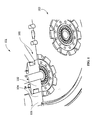
- a fuel nozzle 100 includes a fuel nozzle end cover 104 and a fuel nozzle insert 102.
- the fuel nozzle insert 102 is welded to the fuel nozzle end cover 104 by a welding process, for example, the process shown and described below with reference to FIGS. 2-7 .
- the welding of the fuel nozzle insert 102 to the fuel nozzle end cover 104 is by beam welding (such as laser beam welding and/or electron beam welding) and/or solid state welding (such as friction welding, friction stir welding, explosion welding, electromagnetic pulse welding, co-extrusion welding, cold welding diffusion welding, exothermic welding, high frequency welding, hot pressure welding, induction welding, and roll welding).
- the fuel nozzle insert 102 is capable of being removably secured within the fuel nozzle end cover 104.
- the fuel nozzle 100 can be a portion of any suitable system.
- the fuel nozzle 100 is arranged with one or more additional fuel nozzles 103 and/or is a portion of a gas turbine system 101.
- the fuel nozzle end cover 104 includes a base material 106 defining a cavity 110.
- the base material 106 is any suitable metal or metallic composition.
- the base material 106 is or includes stainless steel.
- the cavity 110 is any suitable geometry.
- the cavity 110 includes substantially cylindrical portions bored out of the base material 106.
- the first cylindrical portion 112 has a first diameter 109 (for example, about 4 inches) that is larger than a second diameter 111 (for example, about 2.3 inches) of the second cylindrical portion 114, the first diameter 109 differing from the second diameter 111.
- the first cylindrical portion 112 has a first depth 113 (for example, about 1.4 inches) and the second cylindrical portion 114 has a second depth 115 (for example, about 2.3 inches), the first depth 113 differing from the second depth 115.
- a frustoconical portion 116 separates the first cylindrical portion 112 and the second cylindrical portion 114.
- a first fuel nozzle insert portion 202 is configured for insertion along a first predetermined insertion direction 203, such as, into the fuel nozzle end cover 104 from the portion of the fuel nozzle end cover 104 proximal to the second cylindrical portion 114 and distal from the first cylindrical portion 112.
- the first fuel nozzle insert portion 202 is or includes stainless steel.
- the first fuel nozzle insert portion 202 includes a first region 204 that is substantially the same length as the depth 113 of the first cylindrical portion 112.
- the first region 204 is substantially cylindrical with a first cylindrical protrusion 205 extending in the first predetermined insertion direction 203.
- the first fuel nozzle insert portion 202 also includes a second region 206 that corresponds with the frustoconical portion 116.
- the second region 206 includes a recessed portion 207 and/or a protruding portion 209 arranged and disposed to be welded to the fuel nozzle end cover 104.
- the first fuel nozzle insert portion 202 also includes a third region 208 that is substantially the same length as the depth 115 of the second cylindrical portion 114.
- the first fuel nozzle insert portion 202 includes a weld region such as a cladded build-up 210 (for example, a nickel-based cladding).
- the cladded build-up 210 extends circumferentially around the third region 208 of the first fuel nozzle insert portion 202.
- the cladded build-up 210 is circumferentially discontinuous.
- the insertion of the first fuel nozzle insert portion 202 into the fuel nozzle end cover 104 includes welding of the cladded build-up 210 in the third region 208 of the first fuel nozzle insert portion 202 and welding of the protruding portion 209 to the fuel nozzle end cover 104, for example, between the frustoconical portion 116 and the second cylindrical portion 114.
- a second fuel nozzle insert portion 402 is configured for insertion in a second predetermined insertion direction 403, for example, a direction opposite the first predetermined insertion direction 203 (see FIG. 2 ) and/or from the portion of the fuel nozzle end cover 104 proximal to the first cylindrical portion 112 and distal from the second cylindrical portion 114.
- the second fuel nozzle insert portion 402 is or includes stainless steel.
- the second fuel nozzle insert portion 402 is substantially the same length as depth 113 of the first cylindrical portion 112.
- the second fuel nozzle insert portion 402 includes a second cylindrical protrusion 405 concentric with the first cylindrical protrusion 205 upon insertion into the end cover 104.
- the second fuel nozzle insert portion 402 includes a wider region 406 arranged and disposed to be welded to the end cover 104, for example, by having an outer diameter (not shown) substantially equal to the first diameter 109 and the cladded build-up 210 on the end cover 104 and/or any other features within the cavity 110 of the end cover 104.
- the second fuel nozzle insert portion 402 also includes a narrower region 408 arranged and disposed for receiving a third fuel nozzle insert portion 602 (see FIG. 6 ), for example, by including a region having the cladded build-up 210.
- FIG. 5 shows, in one embodiment, the second fuel nozzle insert portion 402 inserted into the fuel nozzle end cover 104 and around the first fuel nozzle insert portion 202.
- the second fuel nozzle insert portion is welded into the wider region 406 to the fuel nozzle end cover 104, for example, within the first cylindrical portion 112 and/or abutting the frustoconical portion 116.
- the third fuel nozzle insert portion 602 is configured for insertion in the second predetermined insertion direction 403, for example, a direction opposite the first predetermined insertion direction 203 (see FIG. 2 ) and/or from the portion of the fuel nozzle end cover 104 proximal to the first cylindrical portion 112 and distal from the second cylindrical portion 114.
- the third fuel nozzle insert portion 602 is or includes stainless steel.
- the third fuel nozzle insert portion 602 is arranged and disposed to be inserted into the fuel nozzle end cover 104, around the second fuel nozzle insert portion 402, and/or to extend out of the fuel nozzle end cover 104, for example, forming a lip region 604.
- the third fuel nozzle insert portion 602 includes an insertion region 606 configured to be welded to the cladded build-up 210 of the second fuel nozzle insert portion 402.
- the insertion of the third fuel nozzle insert portion 602 into the fuel nozzle end cover 104 and around the second fuel nozzle insert portion 402 includes welding of the insertion region 606 to the second fuel nozzle insertion portion 402 and/or to the fuel nozzle end cover 104, for example, within the first cylindrical portion 112 distal from the frustoconical portion 116.
- the welding (such as to the first cylindrical portion 112, the second cylindrical portion 114, the frustoconical portion 116, the fuel nozzle end cover 104, the first fuel nozzle insert portion 202, the second fuel nozzle insert portion 402, and/or the third fuel nozzle insert portion 602) is direct or indirect.
- the welding is by the beam welding and/or the solid state welding described above as applied to the components with the cladded build-up 210 or directly between surfaces.
- the welding is by the beam welding and/or the solid state welding through an intermediate material (not shown), such as a sleeve, an insert, a shim, another filler material, features on the fuel nozzle end cover 104, other suitable intermediate materials, or combinations thereof.
- one or more of the intermediate materials include a composition, by weight, of about 10% Ni, about 20% Cr, about 15% W, up to about 3% Fe, about 1.5% Mn, up to about 0.4% Si, about 0.10% C, incidental impurities, and a balance of Co.
- at least one of the features 108 includes a composition, by weight, of about 0.005% C, 0.150% Mn, about 0.005% P, about 0.002% S, about 0.03% Si, about 15.50% Cr, about 16.0% Mo, about 3.50% W, about 0.15% V, about 0.10% Co, about 6.00% Fe, incidental impurities, and a balance of Ni.
- At least one of the features 108 includes a composition, by weight, of about 0.015% C, about 0.48% Si, about 20% Cr, about 1.85% Mn, about 0.15% P, up to about 0.20% Cu, about 0.10% S, up to about 0.60% N, up to about 0.50% Mo, about 10.1 % Ni, incidental impurities, and a balance of Fe.
- one or more of the intermediate materials is a feature 108 positioned within the cavity 110.
- the features 108 are arranged and disposed to facilitate removable securing of one or more of the first fuel nozzle insert portion 202, the second fuel nozzle insert portion 402 (see FIG. 4 ), and the third fuel nozzle insert portion 602 (see FIG. 6 ).
- the features 108 extend into the cavity 110 forming concentric rings corresponding to one or more of the first fuel nozzle insert portion 202, the second fuel nozzle insert portion 402 (see
- FIG. 4 the third fuel nozzle insert portion 602 (see FIG. 6 ).
- the features 108 are positioned in any suitable arrangement.
- one or more of the features 108 is positioned within each of the first cylindrical portion 112 and the second cylindrical portion 114. In other embodiments, only one of the features 108 is positioned in each of the first cylindrical portion 112 and the second cylindrical portion 114. Additionally or alternatively, in one embodiment, one or more of the features 108 extend circumferentially around the cavity 110 through the first cylindrical portion 112 and/or the second cylindrical portion 114. In another embodiment, one or more of the features 108 are discontinuously circumferential within the cavity 110.
- the features 108 and/or other intermediate materials are secured to the base material 106 by any suitable process.
- the securing of the features 108 to the base material 106 results in a predetermined microstructure (not shown) based upon the welding process utilized.
- the securing is performed by one or more of beam welding (such as laser and/or electron beam), friction welding, gas tungsten arc welding (such as tungsten inert gas welding), and gas metal arc welding (such as metal inert gas welding).
- the predetermined microstructure includes a first heat affected zone proximal to the base material 106 that has a predetermined microstructure, a second heat affected zone between the first heat affected zone and a fusion zone, the fusion zone between the second heat affected zone and a third heat affected zone, the third heat affected zone between the fusion zone and a fourth heat affected zone, and the fourth heat affected zone between the third heat affected zone and the unaffected portions of the feature 108.
- each of the zones has a different microstructure.
- other embodiments include characteristics distinguishing from techniques using brazing.
- securing of the features 108 to the base material 106 permits repeated insertion and removal of the insert 102 into the fuel nozzle end cover 104.
- the insert 102 is capable of being removed from the fuel nozzle end cover 104 with little or no damage to the fuel nozzle 100 at least a predetermined number of times, for example, more than three times, more than four times, more than five times, more than ten times, or more than any other suitable number of times.
Landscapes
- Engineering & Computer Science (AREA)
- Mechanical Engineering (AREA)
- Physics & Mathematics (AREA)
- Optics & Photonics (AREA)
- Plasma & Fusion (AREA)
- Combustion & Propulsion (AREA)
- Chemical & Material Sciences (AREA)
- General Engineering & Computer Science (AREA)
- Laser Beam Processing (AREA)
- Welding Or Cutting Using Electron Beams (AREA)
- Butt Welding And Welding Of Specific Article (AREA)
- Pressure Welding/Diffusion-Bonding (AREA)
- Arc Welding In General (AREA)
- Fuel-Injection Apparatus (AREA)
Abstract
Description
- The present invention is directed to fuel nozzles and processes of fabricating fuel nozzles. More particularly, the present invention relates to welded fuel nozzles and processes of fabricating fuel nozzles by welding.
- In general, gas turbines are being subjected to more demanding operation. higher temperatures, harsher environments, use in more diverse environments, and extended duration of use result in challenges for gas turbines and their components. extending the useful life of such components and improving capability for repair of such components can decrease costs associated with the gas turbines and can increase the operational aspects of the gas turbines.
- Known end covers on fuel nozzles in gas turbines have an insert brazed into the end cover. generally, such inserts have four braze joints securing the inserts within the end cover. these braze joints are subject to failure, for example, resulting in leaking proximal to the braze joints. such braze joints can also suffer from a drawback of requiring frequent repair. such repairs can be complex and expensive. in addition, the ability to perform such repairs may be limited.
- Repair of known end covers can result in further leaking that is not capable of being repaired. For example, when an insert is removed for repair, the braze joints are severed. Repeated severing of the braze joints can result in undesirable operational concerns, such as leaking, that is not capable of being adequately repaired. Known end covers suffer from a drawback of being limited to three such iterations of repeated repair.
- Other techniques for securing fuel nozzle inserts within fuel nozzle end covers have been unavailable. In particular, the complex geometry of the insert and the difficulty reaching certain portions within the fuel nozzle when the insert is positioned within the end cover has prevented use of techniques other than brazing.
- A fuel nozzle and a process of fabricating a fuel nozzle that do not suffer from one or more of the above drawbacks would be desirable in the art.
- In a first aspect, the invention resides in a fuel nozzle including a fuel nozzle end cover and a fuel nozzle insert. The fuel nozzle insert is welded to the fuel nozzle end cover by a welding process selected from the group consisting of beam welding, solid state welding, and combinations thereof.
- In another aspect, the invention resides in a fuel nozzle including a fuel nozzle end cover and a fuel nozzle insert. The fuel nozzle insert includes a first fuel nozzle insert portion and a second fuel nozzle insert portion, the first fuel nozzle insert portion being separately welded to the fuel nozzle end cover.
- In another aspect, the invention resides in a process of fabricating a fuel nozzle including providing a fuel nozzle end cover, providing a fuel nozzle insert, and welding the fuel nozzle insert to the fuel nozzle end cover. The welding of the fuel nozzle insert to the fuel nozzle end cover is by a welding process selected from the group consisting of beam welding, solid state welding, and combinations thereof.
- Other features and advantages of the present invention will be apparent from the following more detailed description of the preferred embodiment, taken in conjunction with the accompanying drawings which illustrate, by way of example, the principles of the invention.
- Embodiments of the present invention will now be described, by way of example only, with reference to the accompanying drawings in which:
-
FIG. 1 is a cut-away perspective view of a fuel nozzle positioned in a gas turbine according to the disclosure with a portion of a fuel nozzle insert and a fuel nozzle end cover removed. -
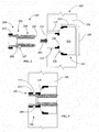
FIG. 2 is a schematic sectioned view of an exemplary fuel nozzle end cover and a first portion of a fuel nozzle insert arranged to be inserted into the fuel nozzle end cover according to the disclosure. -
FIG. 3 is a schematic sectioned view of an exemplary fuel nozzle end cover with a first portion of a fuel nozzle insert welded into the fuel nozzle end cover according to the disclosure. -
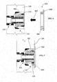
FIG. 4 is a schematic sectioned view of an exemplary fuel nozzle end cover with a first portion of a fuel nozzle insert welded into the fuel nozzle end cover and a second portion of the fuel nozzle insert arranged to be inserted into the fuel nozzle end cover according to the disclosure. -
FIG. 5 is a schematic sectioned view of an exemplary fuel nozzle end cover with a first portion and a second portion of a fuel nozzle insert welded into the fuel nozzle end cover according to the disclosure. -
FIG. 6 is a schematic sectioned view of an exemplary fuel nozzle end cover with a first portion and a second portion of the fuel nozzle insert welded into the fuel nozzle end cover and a third portion of the fuel nozzle insert arranged to be inserted into the fuel nozzle end cover according to the disclosure. -
FIG. 7 is a schematic sectioned view of an exemplary fuel nozzle end cover with a first portion, a second portion, and a third portion of the fuel nozzle insert welded into the fuel nozzle end cover according to the disclosure. - Wherever possible, the same reference numbers will be used throughout the drawings to represent the same parts.
- Provided is an exemplary fuel nozzle and a process of fabricating a fuel nozzle. Embodiments of the present disclosure permit fuel nozzles to be used for longer periods of time, permit fuel nozzles to be repaired in a simpler manner, permit fuel nozzles to be repaired more times (for example, more than three times), decrease operational costs of repair, prevent leaks in fuel nozzles, and combinations thereof.
- Referring to
FIG. 1 , in one embodiment, afuel nozzle 100 includes a fuelnozzle end cover 104 and afuel nozzle insert 102. Thefuel nozzle insert 102 is welded to the fuelnozzle end cover 104 by a welding process, for example, the process shown and described below with reference toFIGS. 2-7 . The welding of the fuel nozzle insert 102 to the fuelnozzle end cover 104 is by beam welding (such as laser beam welding and/or electron beam welding) and/or solid state welding (such as friction welding, friction stir welding, explosion welding, electromagnetic pulse welding, co-extrusion welding, cold welding diffusion welding, exothermic welding, high frequency welding, hot pressure welding, induction welding, and roll welding). - The
fuel nozzle insert 102 is capable of being removably secured within the fuelnozzle end cover 104. Thefuel nozzle 100 can be a portion of any suitable system. In one embodiment, thefuel nozzle 100 is arranged with one or moreadditional fuel nozzles 103 and/or is a portion of agas turbine system 101. - Referring to
FIG. 2 , the fuelnozzle end cover 104 includes abase material 106 defining acavity 110. Thebase material 106 is any suitable metal or metallic composition. In one embodiment, thebase material 106 is or includes stainless steel. - The
cavity 110 is any suitable geometry. In one embodiment, thecavity 110 includes substantially cylindrical portions bored out of thebase material 106. In a further embodiment, the firstcylindrical portion 112 has a first diameter 109 (for example, about 4 inches) that is larger than a second diameter 111 (for example, about 2.3 inches) of the secondcylindrical portion 114, thefirst diameter 109 differing from thesecond diameter 111. In one embodiment, the firstcylindrical portion 112 has a first depth 113 (for example, about 1.4 inches) and the secondcylindrical portion 114 has a second depth 115 (for example, about 2.3 inches), thefirst depth 113 differing from thesecond depth 115. In a further embodiment, afrustoconical portion 116 separates the firstcylindrical portion 112 and the secondcylindrical portion 114. - In one embodiment, a first fuel
nozzle insert portion 202 is configured for insertion along a firstpredetermined insertion direction 203, such as, into the fuelnozzle end cover 104 from the portion of the fuelnozzle end cover 104 proximal to the secondcylindrical portion 114 and distal from the firstcylindrical portion 112. In one embodiment, the first fuelnozzle insert portion 202 is or includes stainless steel. In one embodiment, the first fuelnozzle insert portion 202 includes afirst region 204 that is substantially the same length as thedepth 113 of the firstcylindrical portion 112. In one embodiment, thefirst region 204 is substantially cylindrical with a firstcylindrical protrusion 205 extending in the firstpredetermined insertion direction 203. The first fuelnozzle insert portion 202 also includes asecond region 206 that corresponds with thefrustoconical portion 116. In one embodiment, thesecond region 206 includes a recessedportion 207 and/or a protrudingportion 209 arranged and disposed to be welded to the fuelnozzle end cover 104. The first fuelnozzle insert portion 202 also includes athird region 208 that is substantially the same length as thedepth 115 of the secondcylindrical portion 114. In thethird region 208, the first fuelnozzle insert portion 202 includes a weld region such as a cladded build-up 210 (for example, a nickel-based cladding). In one embodiment, the cladded build-up 210 extends circumferentially around thethird region 208 of the first fuelnozzle insert portion 202. In one embodiment, the cladded build-up 210 is circumferentially discontinuous. - Referring to
FIG. 3 , in one embodiment, the insertion of the first fuelnozzle insert portion 202 into the fuelnozzle end cover 104 includes welding of the cladded build-up 210 in thethird region 208 of the first fuelnozzle insert portion 202 and welding of the protrudingportion 209 to the fuelnozzle end cover 104, for example, between thefrustoconical portion 116 and the secondcylindrical portion 114. - Referring to
FIG. 4 , in one embodiment, a second fuelnozzle insert portion 402 is configured for insertion in a secondpredetermined insertion direction 403, for example, a direction opposite the first predetermined insertion direction 203 (seeFIG. 2 ) and/or from the portion of the fuelnozzle end cover 104 proximal to the firstcylindrical portion 112 and distal from the secondcylindrical portion 114. In one embodiment, the second fuelnozzle insert portion 402 is or includes stainless steel. In one embodiment, the second fuelnozzle insert portion 402 is substantially the same length asdepth 113 of the firstcylindrical portion 112. In one embodiment, the second fuelnozzle insert portion 402 includes a secondcylindrical protrusion 405 concentric with the firstcylindrical protrusion 205 upon insertion into theend cover 104. The second fuelnozzle insert portion 402 includes awider region 406 arranged and disposed to be welded to theend cover 104, for example, by having an outer diameter (not shown) substantially equal to thefirst diameter 109 and the cladded build-up 210 on theend cover 104 and/or any other features within thecavity 110 of theend cover 104. The second fuelnozzle insert portion 402 also includes anarrower region 408 arranged and disposed for receiving a third fuel nozzle insert portion 602 (seeFIG. 6 ), for example, by including a region having the cladded build-up 210. -
FIG. 5 shows, in one embodiment, the second fuelnozzle insert portion 402 inserted into the fuelnozzle end cover 104 and around the first fuelnozzle insert portion 202. The second fuel nozzle insert portion is welded into thewider region 406 to the fuelnozzle end cover 104, for example, within the firstcylindrical portion 112 and/or abutting thefrustoconical portion 116. - Referring to
FIG. 6 , in one embodiment, the third fuelnozzle insert portion 602 is configured for insertion in the secondpredetermined insertion direction 403, for example, a direction opposite the first predetermined insertion direction 203 (seeFIG. 2 ) and/or from the portion of the fuelnozzle end cover 104 proximal to the firstcylindrical portion 112 and distal from the secondcylindrical portion 114. In one embodiment, the third fuelnozzle insert portion 602 is or includes stainless steel. In one embodiment, the third fuelnozzle insert portion 602 is arranged and disposed to be inserted into the fuelnozzle end cover 104, around the second fuelnozzle insert portion 402, and/or to extend out of the fuelnozzle end cover 104, for example, forming alip region 604. In one embodiment, the third fuelnozzle insert portion 602 includes aninsertion region 606 configured to be welded to the cladded build-up 210 of the second fuelnozzle insert portion 402. - Referring to
FIG. 7 , in one embodiment, the insertion of the third fuelnozzle insert portion 602 into the fuelnozzle end cover 104 and around the second fuelnozzle insert portion 402 includes welding of theinsertion region 606 to the second fuelnozzle insertion portion 402 and/or to the fuelnozzle end cover 104, for example, within the firstcylindrical portion 112 distal from thefrustoconical portion 116. - The welding (such as to the first
cylindrical portion 112, the secondcylindrical portion 114, thefrustoconical portion 116, the fuelnozzle end cover 104, the first fuelnozzle insert portion 202, the second fuelnozzle insert portion 402, and/or the third fuel nozzle insert portion 602) is direct or indirect. For example, in one embodiment, the welding is by the beam welding and/or the solid state welding described above as applied to the components with the cladded build-up 210 or directly between surfaces. In another embodiment, the welding is by the beam welding and/or the solid state welding through an intermediate material (not shown), such as a sleeve, an insert, a shim, another filler material, features on the fuelnozzle end cover 104, other suitable intermediate materials, or combinations thereof. - In one embodiment, one or more of the intermediate materials include a composition, by weight, of about 10% Ni, about 20% Cr, about 15% W, up to about 3% Fe, about 1.5% Mn, up to about 0.4% Si, about 0.10% C, incidental impurities, and a balance of Co. In one embodiment, at least one of the
features 108 includes a composition, by weight, of about 0.005% C, 0.150% Mn, about 0.005% P, about 0.002% S, about 0.03% Si, about 15.50% Cr, about 16.0% Mo, about 3.50% W, about 0.15% V, about 0.10% Co, about 6.00% Fe, incidental impurities, and a balance of Ni. In one embodiment, at least one of thefeatures 108 includes a composition, by weight, of about 0.015% C, about 0.48% Si, about 20% Cr, about 1.85% Mn, about 0.15% P, up to about 0.20% Cu, about 0.10% S, up to about 0.60% N, up to about 0.50% Mo, about 10.1 % Ni, incidental impurities, and a balance of Fe. - Referring again to
FIG. 2 , in one embodiment, one or more of the intermediate materials is afeature 108 positioned within thecavity 110. Thefeatures 108 are arranged and disposed to facilitate removable securing of one or more of the first fuelnozzle insert portion 202, the second fuel nozzle insert portion 402 (seeFIG. 4 ), and the third fuel nozzle insert portion 602 (seeFIG. 6 ). For example, thefeatures 108 extend into thecavity 110 forming concentric rings corresponding to one or more of the first fuelnozzle insert portion 202, the second fuel nozzle insert portion 402 (see -
FIG. 4 ), and the third fuel nozzle insert portion 602 (seeFIG. 6 ). - The
features 108 are positioned in any suitable arrangement. For example, in one embodiment, one or more of thefeatures 108 is positioned within each of the firstcylindrical portion 112 and the secondcylindrical portion 114. In other embodiments, only one of thefeatures 108 is positioned in each of the firstcylindrical portion 112 and the secondcylindrical portion 114. Additionally or alternatively, in one embodiment, one or more of thefeatures 108 extend circumferentially around thecavity 110 through the firstcylindrical portion 112 and/or the secondcylindrical portion 114. In another embodiment, one or more of thefeatures 108 are discontinuously circumferential within thecavity 110. - The
features 108 and/or other intermediate materials are secured to thebase material 106 by any suitable process. The securing of thefeatures 108 to thebase material 106 results in a predetermined microstructure (not shown) based upon the welding process utilized. The securing is performed by one or more of beam welding (such as laser and/or electron beam), friction welding, gas tungsten arc welding (such as tungsten inert gas welding), and gas metal arc welding (such as metal inert gas welding). In one embodiment, such as in embodiments with the securing being by beam welding, or friction welding, the predetermined microstructure includes a first heat affected zone proximal to thebase material 106 that has a predetermined microstructure, a second heat affected zone between the first heat affected zone and a fusion zone, the fusion zone between the second heat affected zone and a third heat affected zone, the third heat affected zone between the fusion zone and a fourth heat affected zone, and the fourth heat affected zone between the third heat affected zone and the unaffected portions of thefeature 108. In one embodiment, each of the zones has a different microstructure. As will be appreciated by those skilled in the art, other embodiments include characteristics distinguishing from techniques using brazing. - In one embodiment, securing of the
features 108 to thebase material 106 permits repeated insertion and removal of theinsert 102 into the fuelnozzle end cover 104. For example, in one embodiment, theinsert 102 is capable of being removed from the fuelnozzle end cover 104 with little or no damage to thefuel nozzle 100 at least a predetermined number of times, for example, more than three times, more than four times, more than five times, more than ten times, or more than any other suitable number of times. - While the invention has been described with reference to a preferred embodiment, it will be understood by those skilled in the art that various changes may be made and equivalents may be substituted for elements thereof without departing from the scope of the invention. In addition, many modifications may be made to adapt a particular situation or material to the teachings of the invention without departing from the essential scope thereof. Therefore, it is intended that the invention not be limited to the particular embodiment disclosed as the best mode contemplated for carrying out this invention, but that the invention will include all embodiments falling within the scope of the appended claims.
Claims (12)
- A fuel nozzle (100), comprising:a fuel nozzle end cover (104); anda fuel nozzle insert (102);wherein the fuel nozzle insert (102) is welded to the fuel nozzle end cover (104) by a welding process selected from the group consisting of beam welding, solid state welding, and combinations thereof.
- The fuel nozzle of claim 1, wherein the fuel nozzle insert (102) includes a first fuel nozzle insert portion (202) and a second fuel nozzle insert portion (402), the first fuel nozzle insert portion (202) being separately welded to the fuel nozzle end cover (104).
- The fuel nozzle of claim 1 or 2, wherein the fuel nozzle insert (102) includes a first fuel nozzle insert portion (202) and a second fuel nozzle insert portion (402), the first fuel nozzle insert portion (202) being welded to a first cylindrical portion (112) of the fuel nozzle end cover (104) and the second fuel nozzle insert portion (402) being welded to a second cylindrical portion (114) of the fuel nozzle end cover (104), the first cylindrical portion (112) and the second cylindrical portion (114) differing in diameter.
- The fuel nozzle of claim 3, wherein the second fuel nozzle insert portion (402) is also welded to a frustoconical portion (116) between the first cylindrical portion (112) and the second cylindrical portion (114).
- The fuel nozzle of claim 2, 3 or 4, wherein the fuel nozzle insert (102) further includes a third fuel nozzle insert portion (602).
- The fuel nozzle of claim 5, wherein the third fuel nozzle insert portion (602) is welded to the second fuel nozzle insert portion (114).
- The fuel nozzle of claim 6, wherein the third fuel nozzle insert portion (602) forms a lip region outside of the fuel nozzle end cover (104).
- The fuel nozzle of any of claims 2 to 7, wherein the first fuel nozzle insert portion (202) is configured for insertion along a first predetermined insertion direction (203) and the second fuel nozzle insert portion (402) is configured for insertion along a second predetermined insertion direction (403), the first predetermined insertion direction (203) differing from the second predetermined insertion direction (403).
- The fuel nozzle of any preceding claim, wherein the fuel nozzle insert (102) includes one or more cladded build-ups (210).
- The fuel nozzle of any preceding claim, wherein the fuel nozzle end cover (104) includes a stainless steel base material (106) defining substantially cylindrical cavities (110), having a first diameter (109) and a second diameter (111), the first diameter (109) being larger than the second diameter (111), a first depth (113) and a second depth (115), the first depth (113) being smaller than the second depth (115), and a frustoconical portion (116) separating the substantially cylindrical cavities (110).
- A process of fabricating a fuel nozzle (100), comprising:providing a fuel nozzle end cover (104);providing a fuel nozzle insert (102); andwelding the fuel nozzle insert (102) to the fuel nozzle end cover (104);wherein the welding of the fuel nozzle insert (102) is to the fuel nozzle end cover (104) by a welding process selected from the group consisting of beam welding, solid state welding, and combinations thereof.
- The process of claim 11, wherein the welding of the fuel nozzle insert (102) includes welding of a first fuel nozzle insert portion (202) and a second fuel nozzle insert portion (402), the first fuel nozzle insert portion (202) being separately welded to the fuel nozzle end cover (104).
Priority Applications (1)
| Application Number | Priority Date | Filing Date | Title |
|---|---|---|---|
| PL13150543T PL2614914T3 (en) | 2012-01-12 | 2013-01-08 | A fuel nozzle and process of fabricating a fuel nozzle |
Applications Claiming Priority (1)
| Application Number | Priority Date | Filing Date | Title |
|---|---|---|---|
| US13/348,732 US8950695B2 (en) | 2012-01-12 | 2012-01-12 | Fuel nozzle and process of fabricating a fuel nozzle |
Publications (2)
| Publication Number | Publication Date |
|---|---|
| EP2614914A1 true EP2614914A1 (en) | 2013-07-17 |
| EP2614914B1 EP2614914B1 (en) | 2018-03-14 |
Family
ID=47665893
Family Applications (1)
| Application Number | Title | Priority Date | Filing Date |
|---|---|---|---|
| EP13150543.0A Not-in-force EP2614914B1 (en) | 2012-01-12 | 2013-01-08 | A fuel nozzle and process of fabricating a fuel nozzle |
Country Status (5)
| Country | Link |
|---|---|
| US (1) | US8950695B2 (en) |
| EP (1) | EP2614914B1 (en) |
| JP (1) | JP6043190B2 (en) |
| CN (1) | CN103206723B (en) |
| PL (1) | PL2614914T3 (en) |
Families Citing this family (4)
| Publication number | Priority date | Publication date | Assignee | Title |
|---|---|---|---|---|
| US9174309B2 (en) * | 2012-07-24 | 2015-11-03 | General Electric Company | Turbine component and a process of fabricating a turbine component |
| JP6633982B2 (en) * | 2016-07-01 | 2020-01-22 | 三菱日立パワーシステムズ株式会社 | Gas turbine combustor and method for manufacturing fuel nozzle of gas turbine combustor |
| CN106705123A (en) * | 2016-12-20 | 2017-05-24 | 成都航利航空科技有限责任公司 | Welding structure type fuel spray nozzle of engine |
| JP7096182B2 (en) * | 2019-02-27 | 2022-07-05 | 三菱重工業株式会社 | Gas turbine combustor and gas turbine |
Citations (2)
| Publication number | Priority date | Publication date | Assignee | Title |
|---|---|---|---|---|
| US6112971A (en) * | 1999-05-12 | 2000-09-05 | General Electric Co. | Multi-nozzle combustion end cover vacuum brazing process |
| US20100066035A1 (en) * | 2008-09-16 | 2010-03-18 | General Electric Company | Reusable weld joint for syngas fuel nozzles |
Family Cites Families (9)
| Publication number | Priority date | Publication date | Assignee | Title |
|---|---|---|---|---|
| US5211682A (en) * | 1991-06-11 | 1993-05-18 | Nippondenso Co., Ltd. | Fuel feed apparatus of internal combustion engine and manufacturing method therefor |
| US5947716A (en) * | 1997-04-07 | 1999-09-07 | Eastman Chemical Company | Breech lock heat shield face for burner nozzle |
| JP2002054533A (en) * | 2000-08-16 | 2002-02-20 | Unisia Jecs Corp | Fuel injection valve and method for manufacturing nozzle plate used for fuel injection valve |
| US6969238B2 (en) * | 2003-10-21 | 2005-11-29 | General Electric Company | Tri-property rotor assembly of a turbine engine, and method for its preparation |
| US7287382B2 (en) | 2004-07-19 | 2007-10-30 | John Henriquez | Gas turbine combustor end cover |
| US7237730B2 (en) * | 2005-03-17 | 2007-07-03 | Pratt & Whitney Canada Corp. | Modular fuel nozzle and method of making |
| US8015816B2 (en) * | 2008-06-16 | 2011-09-13 | Delavan Inc | Apparatus for discouraging fuel from entering the heat shield air cavity of a fuel injector |
| US20110083440A1 (en) * | 2009-10-14 | 2011-04-14 | General Electric Company | High strength crossover manifold and method of joining |
| US20110209481A1 (en) * | 2010-02-26 | 2011-09-01 | General Electric Company | Turbine Combustor End Cover |
-
2012
- 2012-01-12 US US13/348,732 patent/US8950695B2/en active Active
-
2013
- 2013-01-08 PL PL13150543T patent/PL2614914T3/en unknown
- 2013-01-08 EP EP13150543.0A patent/EP2614914B1/en not_active Not-in-force
- 2013-01-09 JP JP2013001449A patent/JP6043190B2/en not_active Expired - Fee Related
- 2013-01-11 CN CN201310009858.XA patent/CN103206723B/en not_active Expired - Fee Related
Patent Citations (2)
| Publication number | Priority date | Publication date | Assignee | Title |
|---|---|---|---|---|
| US6112971A (en) * | 1999-05-12 | 2000-09-05 | General Electric Co. | Multi-nozzle combustion end cover vacuum brazing process |
| US20100066035A1 (en) * | 2008-09-16 | 2010-03-18 | General Electric Company | Reusable weld joint for syngas fuel nozzles |
Also Published As
| Publication number | Publication date |
|---|---|
| US8950695B2 (en) | 2015-02-10 |
| CN103206723A (en) | 2013-07-17 |
| CN103206723B (en) | 2016-09-14 |
| US20130181071A1 (en) | 2013-07-18 |
| JP6043190B2 (en) | 2016-12-14 |
| JP2013142534A (en) | 2013-07-22 |
| PL2614914T3 (en) | 2018-08-31 |
| EP2614914B1 (en) | 2018-03-14 |
Similar Documents
| Publication | Publication Date | Title |
|---|---|---|
| EP2676759B1 (en) | Turbine rotor, method of manufacturing such turbine rotor, and steam turbine having such turbine rotor | |
| EP3265266B2 (en) | System for and method of linking by friction welding a first piece of steel to a second piece of steel with use of ni-based alloys adapter | |
| JP4503164B2 (en) | Turbine vane assembly and method of forming the assembly | |
| EP2614914B1 (en) | A fuel nozzle and process of fabricating a fuel nozzle | |
| US8960525B2 (en) | Brazing process and plate assembly | |
| EP3377819B1 (en) | Method for reconditioning fuel nozzle assemblies | |
| EP2626636A2 (en) | Fuel nozzle end cover, fuel nozzle, and process of fabricating a fuel nozzle end cover | |
| US10989345B2 (en) | Process for brazing an accessory on a tube, and corresponding assembly | |
| EP2618061A2 (en) | Process of fabricating a fuel nozzel assembly, process of fabricating a fuel nozzle ring, and a fuel nozzle ring | |
| EP1801348B1 (en) | Method for repairing a turbine engine vane assembly and repaired assembly | |
| EP2208865B1 (en) | Method for repairing distorted gas turbine engine components | |
| EP2789421A1 (en) | Back-shielded welding method and welded structure using the same | |
| KR101539876B1 (en) | Turbine rotor and method for producing turbine rotor | |
| US20160003479A1 (en) | Process of assembling fuel nozzle end cover | |
| EP1712325A1 (en) | Overlay for repairing spline and seal teeth of a mated component comprising a tube and internal slines | |
| EP3130754A1 (en) | Rotating component for a turbomachine and method for providing cooling of a rotating component | |
| US10119473B2 (en) | Component, gas turbine component and method of forming | |
| CN106415133A (en) | Combustor assembly for a gas turbine engine having a braze layer having a centerline eutectic free region |
Legal Events
| Date | Code | Title | Description |
|---|---|---|---|
| PUAI | Public reference made under article 153(3) epc to a published international application that has entered the european phase |
Free format text: ORIGINAL CODE: 0009012 |
|
| AK | Designated contracting states |
Kind code of ref document: A1 Designated state(s): AL AT BE BG CH CY CZ DE DK EE ES FI FR GB GR HR HU IE IS IT LI LT LU LV MC MK MT NL NO PL PT RO RS SE SI SK SM TR |
|
| AX | Request for extension of the european patent |
Extension state: BA ME |
|
| 17P | Request for examination filed |
Effective date: 20140117 |
|
| RBV | Designated contracting states (corrected) |
Designated state(s): AL AT BE BG CH CY CZ DE DK EE ES FI FR GB GR HR HU IE IS IT LI LT LU LV MC MK MT NL NO PL PT RO RS SE SI SK SM TR |
|
| 17Q | First examination report despatched |
Effective date: 20151016 |
|
| STAA | Information on the status of an ep patent application or granted ep patent |
Free format text: STATUS: EXAMINATION IS IN PROGRESS |
|
| GRAP | Despatch of communication of intention to grant a patent |
Free format text: ORIGINAL CODE: EPIDOSNIGR1 |
|
| STAA | Information on the status of an ep patent application or granted ep patent |
Free format text: STATUS: GRANT OF PATENT IS INTENDED |
|
| INTG | Intention to grant announced |
Effective date: 20170928 |
|
| GRAS | Grant fee paid |
Free format text: ORIGINAL CODE: EPIDOSNIGR3 |
|
| GRAA | (expected) grant |
Free format text: ORIGINAL CODE: 0009210 |
|
| STAA | Information on the status of an ep patent application or granted ep patent |
Free format text: STATUS: THE PATENT HAS BEEN GRANTED |
|
| AK | Designated contracting states |
Kind code of ref document: B1 Designated state(s): AL AT BE BG CH CY CZ DE DK EE ES FI FR GB GR HR HU IE IS IT LI LT LU LV MC MK MT NL NO PL PT RO RS SE SI SK SM TR |
|
| REG | Reference to a national code |
Ref country code: GB Ref legal event code: FG4D |
|
| REG | Reference to a national code |
Ref country code: AT Ref legal event code: REF Ref document number: 978375 Country of ref document: AT Kind code of ref document: T Effective date: 20180315 Ref country code: CH Ref legal event code: EP |
|
| REG | Reference to a national code |
Ref country code: IE Ref legal event code: FG4D |
|
| REG | Reference to a national code |
Ref country code: DE Ref legal event code: R096 Ref document number: 602013034321 Country of ref document: DE |
|
| REG | Reference to a national code |
Ref country code: NL Ref legal event code: MP Effective date: 20180314 |
|
| REG | Reference to a national code |
Ref country code: LT Ref legal event code: MG4D |
|
| PG25 | Lapsed in a contracting state [announced via postgrant information from national office to epo] |
Ref country code: HR Free format text: LAPSE BECAUSE OF FAILURE TO SUBMIT A TRANSLATION OF THE DESCRIPTION OR TO PAY THE FEE WITHIN THE PRESCRIBED TIME-LIMIT Effective date: 20180314 Ref country code: ES Free format text: LAPSE BECAUSE OF FAILURE TO SUBMIT A TRANSLATION OF THE DESCRIPTION OR TO PAY THE FEE WITHIN THE PRESCRIBED TIME-LIMIT Effective date: 20180314 Ref country code: CY Free format text: LAPSE BECAUSE OF FAILURE TO SUBMIT A TRANSLATION OF THE DESCRIPTION OR TO PAY THE FEE WITHIN THE PRESCRIBED TIME-LIMIT Effective date: 20180314 Ref country code: LT Free format text: LAPSE BECAUSE OF FAILURE TO SUBMIT A TRANSLATION OF THE DESCRIPTION OR TO PAY THE FEE WITHIN THE PRESCRIBED TIME-LIMIT Effective date: 20180314 Ref country code: NO Free format text: LAPSE BECAUSE OF FAILURE TO SUBMIT A TRANSLATION OF THE DESCRIPTION OR TO PAY THE FEE WITHIN THE PRESCRIBED TIME-LIMIT Effective date: 20180614 Ref country code: FI Free format text: LAPSE BECAUSE OF FAILURE TO SUBMIT A TRANSLATION OF THE DESCRIPTION OR TO PAY THE FEE WITHIN THE PRESCRIBED TIME-LIMIT Effective date: 20180314 |
|
| REG | Reference to a national code |
Ref country code: AT Ref legal event code: MK05 Ref document number: 978375 Country of ref document: AT Kind code of ref document: T Effective date: 20180314 |
|
| PG25 | Lapsed in a contracting state [announced via postgrant information from national office to epo] |
Ref country code: RS Free format text: LAPSE BECAUSE OF FAILURE TO SUBMIT A TRANSLATION OF THE DESCRIPTION OR TO PAY THE FEE WITHIN THE PRESCRIBED TIME-LIMIT Effective date: 20180314 Ref country code: LV Free format text: LAPSE BECAUSE OF FAILURE TO SUBMIT A TRANSLATION OF THE DESCRIPTION OR TO PAY THE FEE WITHIN THE PRESCRIBED TIME-LIMIT Effective date: 20180314 Ref country code: SE Free format text: LAPSE BECAUSE OF FAILURE TO SUBMIT A TRANSLATION OF THE DESCRIPTION OR TO PAY THE FEE WITHIN THE PRESCRIBED TIME-LIMIT Effective date: 20180314 Ref country code: BG Free format text: LAPSE BECAUSE OF FAILURE TO SUBMIT A TRANSLATION OF THE DESCRIPTION OR TO PAY THE FEE WITHIN THE PRESCRIBED TIME-LIMIT Effective date: 20180614 Ref country code: GR Free format text: LAPSE BECAUSE OF FAILURE TO SUBMIT A TRANSLATION OF THE DESCRIPTION OR TO PAY THE FEE WITHIN THE PRESCRIBED TIME-LIMIT Effective date: 20180615 |
|
| PG25 | Lapsed in a contracting state [announced via postgrant information from national office to epo] |
Ref country code: EE Free format text: LAPSE BECAUSE OF FAILURE TO SUBMIT A TRANSLATION OF THE DESCRIPTION OR TO PAY THE FEE WITHIN THE PRESCRIBED TIME-LIMIT Effective date: 20180314 Ref country code: RO Free format text: LAPSE BECAUSE OF FAILURE TO SUBMIT A TRANSLATION OF THE DESCRIPTION OR TO PAY THE FEE WITHIN THE PRESCRIBED TIME-LIMIT Effective date: 20180314 Ref country code: AL Free format text: LAPSE BECAUSE OF FAILURE TO SUBMIT A TRANSLATION OF THE DESCRIPTION OR TO PAY THE FEE WITHIN THE PRESCRIBED TIME-LIMIT Effective date: 20180314 Ref country code: NL Free format text: LAPSE BECAUSE OF FAILURE TO SUBMIT A TRANSLATION OF THE DESCRIPTION OR TO PAY THE FEE WITHIN THE PRESCRIBED TIME-LIMIT Effective date: 20180314 |
|
| PG25 | Lapsed in a contracting state [announced via postgrant information from national office to epo] |
Ref country code: SK Free format text: LAPSE BECAUSE OF FAILURE TO SUBMIT A TRANSLATION OF THE DESCRIPTION OR TO PAY THE FEE WITHIN THE PRESCRIBED TIME-LIMIT Effective date: 20180314 Ref country code: SM Free format text: LAPSE BECAUSE OF FAILURE TO SUBMIT A TRANSLATION OF THE DESCRIPTION OR TO PAY THE FEE WITHIN THE PRESCRIBED TIME-LIMIT Effective date: 20180314 Ref country code: AT Free format text: LAPSE BECAUSE OF FAILURE TO SUBMIT A TRANSLATION OF THE DESCRIPTION OR TO PAY THE FEE WITHIN THE PRESCRIBED TIME-LIMIT Effective date: 20180314 Ref country code: CZ Free format text: LAPSE BECAUSE OF FAILURE TO SUBMIT A TRANSLATION OF THE DESCRIPTION OR TO PAY THE FEE WITHIN THE PRESCRIBED TIME-LIMIT Effective date: 20180314 |
|
| REG | Reference to a national code |
Ref country code: DE Ref legal event code: R097 Ref document number: 602013034321 Country of ref document: DE |
|
| PG25 | Lapsed in a contracting state [announced via postgrant information from national office to epo] |
Ref country code: PT Free format text: LAPSE BECAUSE OF FAILURE TO SUBMIT A TRANSLATION OF THE DESCRIPTION OR TO PAY THE FEE WITHIN THE PRESCRIBED TIME-LIMIT Effective date: 20180716 |
|
| PLBE | No opposition filed within time limit |
Free format text: ORIGINAL CODE: 0009261 |
|
| STAA | Information on the status of an ep patent application or granted ep patent |
Free format text: STATUS: NO OPPOSITION FILED WITHIN TIME LIMIT |
|
| PG25 | Lapsed in a contracting state [announced via postgrant information from national office to epo] |
Ref country code: DK Free format text: LAPSE BECAUSE OF FAILURE TO SUBMIT A TRANSLATION OF THE DESCRIPTION OR TO PAY THE FEE WITHIN THE PRESCRIBED TIME-LIMIT Effective date: 20180314 |
|
| 26N | No opposition filed |
Effective date: 20181217 |
|
| PG25 | Lapsed in a contracting state [announced via postgrant information from national office to epo] |
Ref country code: SI Free format text: LAPSE BECAUSE OF FAILURE TO SUBMIT A TRANSLATION OF THE DESCRIPTION OR TO PAY THE FEE WITHIN THE PRESCRIBED TIME-LIMIT Effective date: 20180314 |
|
| PG25 | Lapsed in a contracting state [announced via postgrant information from national office to epo] |
Ref country code: MC Free format text: LAPSE BECAUSE OF FAILURE TO SUBMIT A TRANSLATION OF THE DESCRIPTION OR TO PAY THE FEE WITHIN THE PRESCRIBED TIME-LIMIT Effective date: 20180314 |
|
| REG | Reference to a national code |
Ref country code: CH Ref legal event code: PL |
|
| GBPC | Gb: european patent ceased through non-payment of renewal fee |
Effective date: 20190108 |
|
| PG25 | Lapsed in a contracting state [announced via postgrant information from national office to epo] |
Ref country code: LU Free format text: LAPSE BECAUSE OF NON-PAYMENT OF DUE FEES Effective date: 20190108 |
|
| REG | Reference to a national code |
Ref country code: BE Ref legal event code: MM Effective date: 20190131 |
|
| REG | Reference to a national code |
Ref country code: IE Ref legal event code: MM4A |
|
| PG25 | Lapsed in a contracting state [announced via postgrant information from national office to epo] |
Ref country code: BE Free format text: LAPSE BECAUSE OF NON-PAYMENT OF DUE FEES Effective date: 20190131 |
|
| PG25 | Lapsed in a contracting state [announced via postgrant information from national office to epo] |
Ref country code: LI Free format text: LAPSE BECAUSE OF NON-PAYMENT OF DUE FEES Effective date: 20190131 Ref country code: CH Free format text: LAPSE BECAUSE OF NON-PAYMENT OF DUE FEES Effective date: 20190131 Ref country code: GB Free format text: LAPSE BECAUSE OF NON-PAYMENT OF DUE FEES Effective date: 20190108 |
|
| PG25 | Lapsed in a contracting state [announced via postgrant information from national office to epo] |
Ref country code: IE Free format text: LAPSE BECAUSE OF NON-PAYMENT OF DUE FEES Effective date: 20190108 |
|
| PGFP | Annual fee paid to national office [announced via postgrant information from national office to epo] |
Ref country code: FR Payment date: 20191219 Year of fee payment: 8 |
|
| PG25 | Lapsed in a contracting state [announced via postgrant information from national office to epo] |
Ref country code: TR Free format text: LAPSE BECAUSE OF FAILURE TO SUBMIT A TRANSLATION OF THE DESCRIPTION OR TO PAY THE FEE WITHIN THE PRESCRIBED TIME-LIMIT Effective date: 20180314 |
|
| PGFP | Annual fee paid to national office [announced via postgrant information from national office to epo] |
Ref country code: IT Payment date: 20200102 Year of fee payment: 8 Ref country code: DE Payment date: 20191218 Year of fee payment: 8 Ref country code: PL Payment date: 20200102 Year of fee payment: 8 |
|
| PG25 | Lapsed in a contracting state [announced via postgrant information from national office to epo] |
Ref country code: MT Free format text: LAPSE BECAUSE OF NON-PAYMENT OF DUE FEES Effective date: 20190108 |
|
| PG25 | Lapsed in a contracting state [announced via postgrant information from national office to epo] |
Ref country code: IS Free format text: LAPSE BECAUSE OF FAILURE TO SUBMIT A TRANSLATION OF THE DESCRIPTION OR TO PAY THE FEE WITHIN THE PRESCRIBED TIME-LIMIT Effective date: 20180714 |
|
| PG25 | Lapsed in a contracting state [announced via postgrant information from national office to epo] |
Ref country code: HU Free format text: LAPSE BECAUSE OF FAILURE TO SUBMIT A TRANSLATION OF THE DESCRIPTION OR TO PAY THE FEE WITHIN THE PRESCRIBED TIME-LIMIT; INVALID AB INITIO Effective date: 20130108 |
|
| REG | Reference to a national code |
Ref country code: DE Ref legal event code: R119 Ref document number: 602013034321 Country of ref document: DE |
|
| PG25 | Lapsed in a contracting state [announced via postgrant information from national office to epo] |
Ref country code: FR Free format text: LAPSE BECAUSE OF NON-PAYMENT OF DUE FEES Effective date: 20210131 |
|
| PG25 | Lapsed in a contracting state [announced via postgrant information from national office to epo] |
Ref country code: DE Free format text: LAPSE BECAUSE OF NON-PAYMENT OF DUE FEES Effective date: 20210803 |
|
| PG25 | Lapsed in a contracting state [announced via postgrant information from national office to epo] |
Ref country code: IT Free format text: LAPSE BECAUSE OF NON-PAYMENT OF DUE FEES Effective date: 20210108 |
|
| PG25 | Lapsed in a contracting state [announced via postgrant information from national office to epo] |
Ref country code: MK Free format text: LAPSE BECAUSE OF FAILURE TO SUBMIT A TRANSLATION OF THE DESCRIPTION OR TO PAY THE FEE WITHIN THE PRESCRIBED TIME-LIMIT Effective date: 20180314 |
|
| PG25 | Lapsed in a contracting state [announced via postgrant information from national office to epo] |
Ref country code: PL Free format text: LAPSE BECAUSE OF NON-PAYMENT OF DUE FEES Effective date: 20210108 |