EP2613323A1 - Nuclear reactor fuel health monitor - Google Patents
Nuclear reactor fuel health monitor Download PDFInfo
- Publication number
- EP2613323A1 EP2613323A1 EP20110821528 EP11821528A EP2613323A1 EP 2613323 A1 EP2613323 A1 EP 2613323A1 EP 20110821528 EP20110821528 EP 20110821528 EP 11821528 A EP11821528 A EP 11821528A EP 2613323 A1 EP2613323 A1 EP 2613323A1
- Authority
- EP
- European Patent Office
- Prior art keywords
- nuclear reactor
- ray detector
- sample container
- gas
- ray
- Prior art date
- Legal status (The legal status is an assumption and is not a legal conclusion. Google has not performed a legal analysis and makes no representation as to the accuracy of the status listed.)
- Granted
Links
- 239000003758 nuclear fuel Substances 0.000 title claims abstract description 69
- 239000002826 coolant Substances 0.000 claims abstract description 180
- 230000005251 gamma ray Effects 0.000 claims abstract description 155
- 238000005259 measurement Methods 0.000 claims abstract description 151
- 230000002285 radioactive effect Effects 0.000 claims description 88
- 229910052740 iodine Inorganic materials 0.000 claims description 42
- 239000011630 iodine Substances 0.000 claims description 42
- ZCYVEMRRCGMTRW-UHFFFAOYSA-N 7553-56-2 Chemical compound [I] ZCYVEMRRCGMTRW-UHFFFAOYSA-N 0.000 claims description 41
- PNEYBMLMFCGWSK-UHFFFAOYSA-N aluminium oxide Inorganic materials [O-2].[O-2].[O-2].[Al+3].[Al+3] PNEYBMLMFCGWSK-UHFFFAOYSA-N 0.000 claims description 18
- 238000005070 sampling Methods 0.000 abstract description 24
- 239000007789 gas Substances 0.000 description 109
- 238000000034 method Methods 0.000 description 32
- XKRFYHLGVUSROY-UHFFFAOYSA-N Argon Chemical compound [Ar] XKRFYHLGVUSROY-UHFFFAOYSA-N 0.000 description 21
- 238000010612 desalination reaction Methods 0.000 description 19
- PXGOKWXKJXAPGV-UHFFFAOYSA-N Fluorine Chemical compound FF PXGOKWXKJXAPGV-UHFFFAOYSA-N 0.000 description 17
- 229910052756 noble gas Inorganic materials 0.000 description 16
- 230000008569 process Effects 0.000 description 16
- 238000012545 processing Methods 0.000 description 16
- 229910052731 fluorine Inorganic materials 0.000 description 15
- 239000011737 fluorine Substances 0.000 description 15
- 238000012544 monitoring process Methods 0.000 description 14
- 239000012071 phase Substances 0.000 description 14
- 239000004065 semiconductor Substances 0.000 description 14
- 230000008929 regeneration Effects 0.000 description 13
- 238000011069 regeneration method Methods 0.000 description 13
- 238000001816 cooling Methods 0.000 description 11
- 238000007872 degassing Methods 0.000 description 10
- 229910052786 argon Inorganic materials 0.000 description 8
- 238000001514 detection method Methods 0.000 description 8
- 238000010586 diagram Methods 0.000 description 8
- XLYOFNOQVPJJNP-UHFFFAOYSA-N water Substances O XLYOFNOQVPJJNP-UHFFFAOYSA-N 0.000 description 6
- 238000004458 analytical method Methods 0.000 description 5
- 238000005349 anion exchange Methods 0.000 description 5
- 239000000470 constituent Substances 0.000 description 5
- 238000002203 pretreatment Methods 0.000 description 5
- 238000012546 transfer Methods 0.000 description 5
- IJGRMHOSHXDMSA-UHFFFAOYSA-N Atomic nitrogen Chemical compound N#N IJGRMHOSHXDMSA-UHFFFAOYSA-N 0.000 description 4
- 230000008859 change Effects 0.000 description 4
- 238000004590 computer program Methods 0.000 description 4
- 239000007788 liquid Substances 0.000 description 4
- 230000035945 sensitivity Effects 0.000 description 3
- 238000006243 chemical reaction Methods 0.000 description 2
- 238000005253 cladding Methods 0.000 description 2
- 238000004891 communication Methods 0.000 description 2
- 239000000498 cooling water Substances 0.000 description 2
- 230000004992 fission Effects 0.000 description 2
- 230000006870 function Effects 0.000 description 2
- 238000009434 installation Methods 0.000 description 2
- 239000007791 liquid phase Substances 0.000 description 2
- 238000012423 maintenance Methods 0.000 description 2
- 238000000691 measurement method Methods 0.000 description 2
- 229910052757 nitrogen Inorganic materials 0.000 description 2
- 238000011144 upstream manufacturing Methods 0.000 description 2
- UFHFLCQGNIYNRP-UHFFFAOYSA-N Hydrogen Chemical compound [H][H] UFHFLCQGNIYNRP-UHFFFAOYSA-N 0.000 description 1
- DGAQECJNVWCQMB-PUAWFVPOSA-M Ilexoside XXIX Chemical compound C[C@@H]1CC[C@@]2(CC[C@@]3(C(=CC[C@H]4[C@]3(CC[C@@H]5[C@@]4(CC[C@@H](C5(C)C)OS(=O)(=O)[O-])C)C)[C@@H]2[C@]1(C)O)C)C(=O)O[C@H]6[C@@H]([C@H]([C@@H]([C@H](O6)CO)O)O)O.[Na+] DGAQECJNVWCQMB-PUAWFVPOSA-M 0.000 description 1
- QVGXLLKOCUKJST-UHFFFAOYSA-N atomic oxygen Chemical compound [O] QVGXLLKOCUKJST-UHFFFAOYSA-N 0.000 description 1
- 238000009835 boiling Methods 0.000 description 1
- 238000005341 cation exchange Methods 0.000 description 1
- 150000001768 cations Chemical class 0.000 description 1
- 239000012141 concentrate Substances 0.000 description 1
- 230000000694 effects Effects 0.000 description 1
- 239000000284 extract Substances 0.000 description 1
- 238000000084 gamma-ray spectrum Methods 0.000 description 1
- 238000007429 general method Methods 0.000 description 1
- 239000001257 hydrogen Substances 0.000 description 1
- 229910052739 hydrogen Inorganic materials 0.000 description 1
- 239000012535 impurity Substances 0.000 description 1
- PNDPGZBMCMUPRI-UHFFFAOYSA-N iodine Chemical compound II PNDPGZBMCMUPRI-UHFFFAOYSA-N 0.000 description 1
- 229910052743 krypton Inorganic materials 0.000 description 1
- DNNSSWSSYDEUBZ-UHFFFAOYSA-N krypton atom Chemical compound [Kr] DNNSSWSSYDEUBZ-UHFFFAOYSA-N 0.000 description 1
- 239000004973 liquid crystal related substance Substances 0.000 description 1
- 230000007246 mechanism Effects 0.000 description 1
- 239000001301 oxygen Substances 0.000 description 1
- 229910052760 oxygen Inorganic materials 0.000 description 1
- 230000002093 peripheral effect Effects 0.000 description 1
- 230000005855 radiation Effects 0.000 description 1
- 230000000717 retained effect Effects 0.000 description 1
- 238000007789 sealing Methods 0.000 description 1
- 229910052708 sodium Inorganic materials 0.000 description 1
- 239000011734 sodium Substances 0.000 description 1
- 238000004326 stimulated echo acquisition mode for imaging Methods 0.000 description 1
Images


Classifications
-
- G—PHYSICS
- G01—MEASURING; TESTING
- G01T—MEASUREMENT OF NUCLEAR OR X-RADIATION
- G01T1/00—Measuring X-radiation, gamma radiation, corpuscular radiation, or cosmic radiation
- G01T1/16—Measuring radiation intensity
- G01T1/167—Measuring radioactive content of objects, e.g. contamination
-
- G—PHYSICS
- G01—MEASURING; TESTING
- G01T—MEASUREMENT OF NUCLEAR OR X-RADIATION
- G01T7/00—Details of radiation-measuring instruments
- G01T7/02—Collecting means for receiving or storing samples to be investigated and possibly directly transporting the samples to the measuring arrangement; particularly for investigating radioactive fluids
-
- G—PHYSICS
- G21—NUCLEAR PHYSICS; NUCLEAR ENGINEERING
- G21C—NUCLEAR REACTORS
- G21C17/00—Monitoring; Testing ; Maintaining
- G21C17/02—Devices or arrangements for monitoring coolant or moderator
-
- G—PHYSICS
- G21—NUCLEAR PHYSICS; NUCLEAR ENGINEERING
- G21C—NUCLEAR REACTORS
- G21C17/00—Monitoring; Testing ; Maintaining
- G21C17/02—Devices or arrangements for monitoring coolant or moderator
- G21C17/022—Devices or arrangements for monitoring coolant or moderator for monitoring liquid coolants or moderators
-
- G—PHYSICS
- G21—NUCLEAR PHYSICS; NUCLEAR ENGINEERING
- G21C—NUCLEAR REACTORS
- G21C17/00—Monitoring; Testing ; Maintaining
- G21C17/06—Devices or arrangements for monitoring or testing fuel or fuel elements outside the reactor core, e.g. for burn-up, for contamination
-
- G—PHYSICS
- G21—NUCLEAR PHYSICS; NUCLEAR ENGINEERING
- G21C—NUCLEAR REACTORS
- G21C1/00—Reactor types
- G21C1/02—Fast fission reactors, i.e. reactors not using a moderator ; Metal cooled reactors; Fast breeders
- G21C1/022—Fast fission reactors, i.e. reactors not using a moderator ; Metal cooled reactors; Fast breeders characterised by the design or properties of the core
-
- Y—GENERAL TAGGING OF NEW TECHNOLOGICAL DEVELOPMENTS; GENERAL TAGGING OF CROSS-SECTIONAL TECHNOLOGIES SPANNING OVER SEVERAL SECTIONS OF THE IPC; TECHNICAL SUBJECTS COVERED BY FORMER USPC CROSS-REFERENCE ART COLLECTIONS [XRACs] AND DIGESTS
- Y02—TECHNOLOGIES OR APPLICATIONS FOR MITIGATION OR ADAPTATION AGAINST CLIMATE CHANGE
- Y02E—REDUCTION OF GREENHOUSE GAS [GHG] EMISSIONS, RELATED TO ENERGY GENERATION, TRANSMISSION OR DISTRIBUTION
- Y02E30/00—Energy generation of nuclear origin
- Y02E30/30—Nuclear fission reactors
Definitions
- the present invention relates to a nuclear reactor fuel integrity monitor which monitors a nuclear reactor fuel state.
- a pressurized water reactor or a boiling water reactor (BWR) uses light water as a nuclear reactor coolant and a neutron moderator.
- the nuclear reactor coolant cools a cladding pipe of nuclear reactor fuel so as to decrease the temperature of the cladding pipe.
- a nuclear reactor coolant and a gas dissolved in the nuclear reactor coolant are periodically sampled from the nuclear reactor. Then, a concentration of a specific radionuclide which may be discharged from the nuclear reactor fuel to the nuclear reactor coolant and the dissolved gas is monitored.
- Patent Literature 1 discloses a radioactive gas measuring device which extracts the gas dissolved in the nuclear reactor coolant, seals the gas in a sample chamber, and monitors a radiation level of a radioactive gas.
- the operation in which the gas dissolved in the nuclear reactor coolant is extracted is sealed in the sample chamber, and is measured by the radioactive gas measuring device, some time is necessary for extracting the dissolved gas. Further, the operation of sealing the dissolved gas in the sample chamber is an operation which needs an operator's labor.
- the invention is made in view of such circumstances, and it is an object of the invention to provide a nuclear reactor fuel integrity monitor capable of periodically sampling a coolant or a dissolved gas of a nuclear reactor from a sampling point without an operator's labor and measuring a concentration of a specific radionuclide included in the coolant or the dissolved gas of the nuclear reactor.
- a nuclear reactor fuel integrity monitor including: a ⁇ -ray detector which detects ⁇ -ray of a specific radionuclide of a subject measurement medium of a nuclear reactor; a sample container which retains the subject measurement medium therein and surrounds the circumference of the ⁇ -ray detector; and a measurement control device which performs a control so that a predetermined amount of the subject measurement medium is introduced into the sample container and calculates a concentration of the specific radionuclide from ⁇ -ray data per each unit time detected by the ⁇ -ray detector and a volume of the subject measurement medium introduced into the sample container.
- the sample container is formed in a shape in which the subject measurement medium surrounds the ⁇ -ray detector, it is possible to increase the volume of the subject measurement medium which may be detected by the ⁇ -ray detector. As a result, since the amount of the ⁇ -ray which may be detected by the ⁇ -ray detector 31 increases, there is no need to perform the operation of concentrating the subject measurement medium so as to improve the detection efficiency of the ⁇ -ray detector 31. Further, since the supply of the subject measurement medium is controlled so that a predetermined amount of the subject measurement medium is introduced into the sample container, it is possible to periodically measure the ⁇ -ray of the subject measurement medium introduced into the sample container without the operator's labor. Further, according to the invention, it is possible to calculate the concentration for each specific radionuclide.
- the sample container may be formed in a hollow shape and be wound on the ⁇ -ray detector so as to surround the ⁇ -ray detector in a spiral shape.
- the sample container is formed in a hollow shape, it is possible to efficiently discharge the subject measurement medium inside the sample container without leaving the subject measurement medium therein. Further, since the sample container is wound on the ⁇ -ray detector so as to surround the ⁇ -ray detector in a spiral shape, it is possible to increase the volume of the subject measurement medium which may be detected by the ⁇ -ray detector. As a result, it is possible to ensure the detection output of the ⁇ -ray detector.
- the subject measurement medium may be a gas and the specific radionuclide may be radioxenon.
- the radioxenon is discharged from the nuclear reactor fuel, it is possible to generate an alarm at an early timing.
- the sample container includes a recess portion and the ⁇ -ray detector is disposed in the recess portion. Accordingly, the subject measurement medium surrounds the circumference of the ⁇ -ray detector and the amount of the ⁇ -ray which is received by the ⁇ -ray detector from the subject measurement medium increases.
- the subject measurement medium is a coolant of the nuclear reactor and the specific radionuclide is radioactive iodine.
- the radioactive iodine is discharged from the nuclear reactor fuel, it is possible to generate an alarm at an early timing.
- an inlet side of the sample container is provided with an activated alumina column, and the coolant passing through the activated alumina column is introduced into the sample container.
- a nuclear reactor fuel integrity monitor includes: a first ⁇ -ray detector which detects ⁇ -ray of a first specific radionuclide contained in a gas as a subject measurement medium of a nuclear reactor; a first sample container which retains the gas inside a hollow portion thereof and is wound on the first ⁇ -ray detector so as to surround the first ⁇ -ray detector in a spiral shape; a second ⁇ -ray detector which detects ⁇ -ray of a second specific radionuclide contained in a coolant as a subject measurement medium of the nuclear reactor; a second sample container which retains the coolant therein and includes a recess portion for disposing the second ⁇ -ray detector therein; and a measurement control device which performs a control so that a predetermined amount of the gas is introduced into the first sample container and a predetermined amount of the coolant is introduced into the second sample container, and calculates concentrations of the first and second specific radionuclides from ⁇ -ray data per unit time detected by the
- the coolant or the dissolved gas of the nuclear reactor is periodically sampled without the operator's labor, and hence the concentration of the specific radionuclide included in the coolant or the dissolved gas may be measured.
- FIG. 1 is a schematic diagram illustrating a nuclear plant.
- a nuclear plant 1 is a nuclear generation facility.
- a nuclear reactor 2 which constitutes the nuclear plant 1 is a pressurized water reactor.
- the nuclear reactor 2 In the nuclear plant 1, the nuclear reactor 2, a steam generator 3, a pressurizer 4, a nuclear reactor coolant pump 5, and a regeneration heat exchanger 11 are arranged inside a containment 1W. Further, a turbine 8, a condenser 9, and a power generator 10 are arranged outside the containment 1W.
- a nuclear reactor fuel 2C is disposed inside a pressure container. Further, a nuclear reactor coolant (which corresponds to cooling water, for example, light water) C1 is charged into the pressure container.
- the nuclear reactor coolant pump 5 is connected to the nuclear reactor 2 by a first nuclear reactor coolant supply passageway 6A, and the nuclear reactor 2 is connected to the steam generator 3 by a second nuclear reactor coolant supply passageway 6B. Further, the steam generator 3 is connected to the nuclear reactor coolant pump 5 by a nuclear reactor coolant collecting passageway 6C.
- the nuclear reactor coolant C1 which is ejected from the nuclear reactor coolant pump 5 passes through the first nuclear reactor coolant supply passageway 6A so as to be supplied into the pressure container of the nuclear reactor 2. Then, the nuclear reactor coolant C1 is heated by the thermal energy which is generated by the nuclear fission reaction of the nuclear reactor fuel 2C disposed inside the pressure container. The heated nuclear reactor coolant C1 passes through the second nuclear reactor coolant supply passageway 6B so as to be supplied to the steam generator 3.
- the nuclear reactor coolant C1 passes through a heat transfer pipe 3T of the steam generator 3, flows out of the steam generator 3, passes through the nuclear reactor coolant collecting passageway 6C, returns to the nuclear reactor coolant pump 5, and is ejected again from the first nuclear reactor coolant supply passageway 6A into the pressure container of the nuclear reactor 2.
- the steam generator 3 includes a plurality of the heat transfer pipes 3T, and a secondary coolant C2 outside the heat transfer pipe 3T is heated and boiled by the nuclear reactor coolant C1 which flows inside the heat transfer pipe 3T, so that pressurized hot steam of the secondary coolant C2 is generated.
- the steam generator 3 is connected to the turbine 8 by a steam supply passageway 7S, and the condenser 9 is connected to the steam generator 3 by a secondary coolant collecting passageway 7R. Accordingly, the pressurized hot steam of the secondary coolant C2 which is generated by the steam generator 3 passes through the steam supply passageway 7S so as to be supplied to the turbine 8, thereby driving the turbine 8. Then, power is generated by the power generator 10 which is connected to the driving shaft of the turbine 8.
- the secondary coolant C2 which is used to drive the turbine 8 is liquefied by the condenser 9, and passes through the secondary coolant collecting passageway 7R so as to be sent to the steam generator 3 again.
- the nuclear reactor 2 is a pressurized water reactor, and the pressurizer 4 is connected to the second nuclear reactor coolant supply passageway 6B. Then, the pressurizer 4 pressurizes the nuclear reactor coolant C1 inside the second nuclear reactor coolant supply passageway 6B. With such a structure, the nuclear reactor coolant C1 is not boiled even when the coolant is heated by the thermal energy generated by the nuclear fission reaction of the nuclear reactor fuel 2C, and circulates the nuclear reactor 2 and the cooling system thereof in a liquid state.
- the cooling system of the nuclear reactor 2 is a system which includes the nuclear reactor coolant pump 5, the first nuclear reactor coolant supply passageway 6A, the second nuclear reactor coolant supply passageway 6B, the steam generator 3, and the nuclear reactor coolant collecting passageway 6C and through which the nuclear reactor coolant C1 flows.
- a desalination tower 16 is installed.
- the desalination tower 16 includes a first desalination tower 16A and a second desalination tower 16B, and is installed outside the containment 1W.
- the first desalination tower 16A is a coolant hot-bed desalination tower
- the second desalination tower 16B is a coolant cation desalination tower.
- the nuclear reactor coolant C1 which is extracted from the inlet side (the upstream side) of the nuclear reactor coolant pump 5 is supplied from the cooling system of the nuclear reactor 2 to the desalination tower 16 so that a desalination process is performed thereon, and the nuclear reactor coolant C1 returns to the outlet side (the downstream side) of the nuclear reactor coolant pump 5.
- a desalination process system of the nuclear reactor coolant C1 includes a nuclear reactor coolant extracting passageway 13A, the regeneration heat exchanger 11, a nuclear reactor coolant passageway 13B, a non-regeneration heat exchanger 12, a nuclear reactor coolant passageway 13C, the desalination tower 16, a nuclear reactor coolant passageway 13D, a volume control tank 14, and nuclear reactor coolant returning passageways 13E and 13F.
- the nuclear reactor coolant extracting passageway 13A connects the nuclear reactor coolant collecting passageway 6C constituting the cooling system of the nuclear reactor 2 to the regeneration heat exchanger 11.
- the regeneration heat exchanger 11 is connected to the non-regeneration heat exchanger 12 by the nuclear reactor coolant passageway 13B, and the non-regeneration heat exchanger 12 is connected to the desalination tower 16 by the nuclear reactor coolant passageway 13C.
- the desalination tower 16 is connected to the volume control tank 14 by the nuclear reactor coolant passageway 13D, and the volume control tank 14 is connected to the regeneration heat exchanger 11 by the nuclear reactor coolant returning passageway 13E. Further, the regeneration heat exchanger 11 is connected to the first nuclear reactor coolant supply passageway 6A by the nuclear reactor coolant returning passageway 13F.
- the nuclear reactor coolant returning passageway 13E is provided with a charging pump 15.
- the nuclear reactor coolant C1 is extracted from the nuclear reactor coolant extracting passageway 13A, that is, the inlet side (the upstream side) of the nuclear reactor coolant pump 5.
- the nuclear reactor coolant C1 which is extracted from the cooling system of the nuclear reactor 2 is guided to the regeneration heat exchanger 11, and passes through the nuclear reactor coolant passageway 13B, the non-regeneration heat exchanger 12, and the nuclear reactor coolant passageway 13C so as to be guided to the desalination tower 16, where the desalination process is performed.
- the nuclear reactor coolant C1 subjected to the desalination process passes through the nuclear reactor coolant passageway 13D and is temporarily accumulated in the volume control tank 14.
- the nuclear reactor coolant is sent to the regeneration heat exchanger 11 by the charging pump 15 which is installed in the nuclear reactor coolant returning passageway 13E.
- the nuclear reactor coolant C1 which passes by the regeneration heat exchanger 11 passes through the nuclear reactor coolant returning passageway 13F so as to be returned to the first nuclear reactor coolant supply passageway 6A, that is, the outlet side (the downstream side) of the nuclear reactor coolant pump 5.
- the nuclear reactor coolant C1 inside the volume control tank 14 is separated into a liquid phase and a gas phase, and a gas phase portion 14a including a gas G exists along with the nuclear reactor coolant C1. Then, the volume control tank 14 is provided with a gas phase sampling point 21 which may sample a part of the gas G of the gas phase portion 14a as the dissolved gas.
- the installation of the gas phase sampling point 21 is not limited to the volume control tank 14 as long as there is a tank which has the nuclear reactor coolant C1 therein and in which the nuclear reactor coolant exists while being separated into a liquid phase and a gas phase.
- the nuclear reactor coolant passageway 13C which constitutes the desalination process system of the nuclear reactor coolant C1 is provided with a nuclear reactor coolant sampling point 25 which may sample a part of the nuclear reactor coolant C1. Furthermore, the installation of the nuclear reactor coolant sampling point 25 is not limited to the nuclear reactor coolant passageway 13C.
- FIG. 2 is a schematic diagram illustrating an example of the nuclear reactor fuel integrity monitor according to the first embodiment.
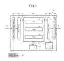
- FIG. 3 is a schematic diagram illustrating a measurement control device.
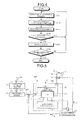
- FIG. 4 is a flowchart illustrating a procedure of monitoring the nuclear reactor fuel state.
- a nuclear reactor fuel integrity monitor 100 includes a radioactive noble gas detecting device 30, a measurement control device 80, opening and closing valves 41 and 42, and valve control units 43 and 44.
- the radioactive noble gas detecting device 30 is disposed between the gas phase sampling point 21 and an exhaust process connection point 45 and is connected to the gas phase sampling point 21 and the exhaust process connection point 45 through a gas passageway 24A, a gas passageway 24C, and a gas passageway 46.
- the gas G which is supplied from the gas phase sampling point 21 is branched from the gas passageway 24A into the gas passageway 24C and a gas passageway 24B by a branch point 23.
- the gas G which is branched to the gas passageway 24B is supplied to an analysis device 22.
- the radioactive noble gas detecting device 30 includes a ⁇ -ray detector 31, a sample loop 32 as a sample container, and a lead shield 33.
- Radioactive argon (Ar-41), radioactive krypton (Kr-85, Kr-85 m, Kr-87), and radioxenon (Xe-133, Xe-135) may be dissolved as a radioactive noble gas in the nuclear reactor coolant C1.
- the radioactive noble gas detecting device 30 may detect radioxenon (Xe-133, Xe-135).
- a NaI scintillation detector or a Ge-semiconductor detector is used as the ⁇ -ray detector 31.
- the NaI scintillation detector and the Ge-semiconductor detector may obtain a ⁇ -ray spectrum. Since the detection efficiency and the maintenance workability of the NaI scintillation detector are better than those of the Ge-semiconductor detector, it is desirable to use the former as the ⁇ -ray detector 31.
- the resolution of the NaI scintillation detector is about 80 keV at FWHM (Full width at half maximum).
- NaI scintillation detector may discriminate and measure the ⁇ -ray of 81.0 keV emitted from Xe--133 and the ⁇ -ray of 249.7 keV emitted from Xe-135. Since the count rates of the respective energy regions of Xe-133 and Xe-135 are discriminated and calculated, both radionuclides of Xe-133 and Xe-135 may be quantitatively measured. Furthermore, in the NaI scintillation detector, it is desirable that the periphery of the NaI scintillation detector be maintained at a constant temperature from the viewpoint of preventing noise.
- the Ge-semiconductor detector When the resolution of the ⁇ -ray detector 31 is increased and a radioactive noble gas other than both radionuclides of Xe-133 and Xe-135 is detected, the Ge-semiconductor detector is desirable as the ⁇ -ray detector 31 compared to the NaI scintillation detector. However, since the Ge-semiconductor detector has about 10% of the ⁇ -ray sensitivity of the NaI scintillation detector, it is desirable to increase the volume of the gas G as the subject measurement medium when using the Ge-semiconductor detector as the ⁇ -ray detector 31.
- the sample loop 32 is a sample container which retains the gas G as a subject measurement medium therein.
- the sample loop 32 is formed in a tubular shape, and may retain the gas G as the subject measurement medium inside the hollow portion. Since the sample loop 32 is formed in a hollow tubular shape, the gas G may be easily purged. For this reason, the replacement may be easily performed by supplying a new subject measurement medium into the sample loop 32.
- the sample loop 32 is disposed so as to surround the circumference of the ⁇ -ray detector 31.
- the sample loop 32 is wound on the circumference of the ⁇ -ray detector 31 in a spiral shape, and surrounds the circumference of the ⁇ -ray detector 31.
- the gas G as the subject measurement medium surrounds the circumference of the ⁇ -ray detector 31 which is held by the sample loop 32.
- the internal volume of the sample loop 32 and the number of times in which the sample loop is wound on the circumference of the ⁇ -ray detector 31 in a spiral shape are set so as to match the concentration of the radionuclide included in the gas G as the subject measurement medium.
- the internal volume of the sample loop 32 is about 20 ml.
- the sample loop 32 when the sample loop 32 is degraded or the internal volume is changed, the sample loop 32 needs to be changed. For this reason, it is desirable that the sample loop 32 be separated from the circumference of the ⁇ -ray detector 31 for the replacement.
- the lead shield 33 is a lead plate.
- the lead shield 33 is thickened as much as possible and is disposed so as to surround at least the ⁇ -ray detector 31 and the sample loop 32.
- the lead shield 33 prevents the ⁇ -ray from reaching the ⁇ -ray detector 31 from the outside of the radioactive noble gas detecting device 30.
- the gas passageway 24A, the gas passageway 24C, and the gas passageway 46 are formed in a tubular shape, so that the gas G may pass therethrough.
- the opening and closing valve 41 is connected to the gas passageway 24C, and may adjust the amount of the gas G which is supplied from the gas passageway 24C to the radioactive noble gas detecting device 30.
- the opening and closing valve 42 is connected to the gas passageway 46, and may adjust the amount of the gas G which is discharged from the radioactive noble gas detecting device 30 to the gas passageway 46.
- the valve control units 43 and 44 control the opening and closing degrees of the opening and closing valves 41 and 42.
- the gas G which is supplied from the gas phase sampling point 21 is supplied to the gas passageway 24A.
- the gas passageway 24A supplies the gas G to the branch point 23.
- the branch point 23 distributes the gas G to the gas passageway 24B and the gas passageway 24C.
- the radioactive noble gas detecting device 30 may receive the gas G supplied from the gas passageway 24C through the opening and closing valve 41. Further, when the opening and closing valves 41 and 42 are opened, the gas G supplied from the gas passageway 24C is extruded, so that the gas inside the radioactive noble gas detecting device 30 is discharged to the gas passageway 46 through the opening and closing valve 42.
- the exhaust process connection point 45 is connected to a facility that appropriately treats the gas G supplied from the gas passageway 46.
- the ⁇ -ray detector 31 of the radioactive noble gas detecting device 30 is connected to the measurement control device 80. Then, the ⁇ -ray detector 31 is electrically connected to the measurement control device 80 so as to transmit and receive the measurement data is or the instruction signal.
- the measurement control device 80 is electrically connected to the valve control unit 43 and the valve control unit 44 so that the instruction signal id may be transmitted to the valve control unit 43 which controls the opening and closing degree of the opening and closing valve 41 and the valve control unit 44 which controls the opening and closing degree of the opening and closing valve 42.
- the gas G which is supplied from the gas passageway 24B moves to the analysis device 22.
- the analysis device 22 detects the concentration and the like of hydrogen or oxygen included in the gas G.
- the nuclear reactor fuel integrity monitor 100 of the first embodiment commonly shares the gas phase sampling point 21 and the gas passageway 24A with the analysis device 22.
- the measurement control device 80 includes an input processing circuit 81, an input port 82, a process unit 90, a storage unit 94, an output port 83, an output processing circuit 84, and a display device 85.
- the measurement control device further includes an input device 86 such as a keyboard if necessary.
- the process unit 90 includes, for example, a CPU (Central Processing Unit) 91, a RAM 92, and a ROM 93.
- the process unit 90, the storage unit 94, the input port 82, and the output port 83 are connected to one another through a bus 87, a bus 88, and a bus 89.
- the bus 87, the bus 88, and the bus 89 the CPU 91 of the process unit 90 may exchange control data with or transmit an instruction to any one of the storage unit 94, the input port 82, and the output port 83.
- the input processing circuit 81 is connected to the input port 82.
- the input processing circuit 81 is connected with the measurement data is from the ⁇ -ray detector 31. Then, the measurement data is which is output from the ⁇ -ray detector 31 of the radioactive noble gas detecting device 30 is converted into a signal which may be used by the process unit 90 through a noise filter or an A/D converter provided in the input processing circuit 81, and is transmitted to the process unit 90 through the input port 82. Accordingly, the process unit 90 may acquire information necessary for calculating the concentration of the radionuclide.
- the output port 83 is connected with the output processing circuit 84.
- the output processing circuit 84 is connected with the display device 85 or the external output terminal.
- the output processing circuit 84 includes a display device control circuit, a valve control signal circuit for the opening and closing valve, a signal amplifying circuit, and the like.
- the output processing circuit 84 outputs the concentration of the radionuclide calculated by the process unit 90 as a display signal for displaying the concentration on the display device 85 or outputs the concentration as the instruction signal id transmitted to the ⁇ -ray detector 31 and the valve control units 43 and 44.
- the display device 85 for example, a liquid crystal display panel, a CRT (Cathode Ray Tube), or the like may be used.
- the storage unit 94 stores a computer program including a procedure of monitoring the nuclear reactor fuel state, a database of radionuclide concentration measurement data, and the like.
- the storage unit 94 may include a volatile memory such as a RAM (Random Access Memory), a non-volatile memory such as a flash memory, and a hard disk or the combination of these.
- the computer program may execute a procedure of monitoring the nuclear reactor fuel state by the combination with the computer program which is previously stored in the process unit 90. Further, the measurement control device 80 may execute the procedure of monitoring the nuclear reactor fuel state by using exclusive hardware instead of the computer program.
- the procedure of monitoring the nuclear reactor fuel state may be realized by executing the prepared program through a computer system such as a personal computer, a workstation, or a plant control computer.
- the program is stored in a storage device such as a hard disk or a storage medium such as a flexible disk (FD), a ROM, a CD-ROM, a MO, a DVD, and a flash memory which may be read by the computer, and may be executed by reading out the program from the storage medium through the computer.
- FD flexible disk
- ROM read-only memory
- MO Compact Disc
- DVD digital versatile disc
- flash memory which may be read by the computer
- the "computer system” mentioned herein includes hardware such as an OS or a peripheral device.
- the "storage medium which may be read out by the computer” includes the case of dynamically storing the program for a short time as in a communication line used when transmitting the program through a network such as an internet or a communication network such as a phone line or the case of storing the program for a predetermined time as in a volatile memory inside a computer system which becomes a server or a client in that case.
- the program may realize a part of the above-described function and further realize the above-described function by the combination with the program previously stored in the computer system.
- the CPU 91 of the process unit 90 included in the measurement control device 80 illustrated in FIGS. 2 and 3 receives the measurement request input from the input device 86 through the input processing circuit 81 and the input port 82, and temporarily stores the measurement request in the RAM 92 or the storage unit 94 (step S101). Alternatively, the CPU 91 stores the measurement request which is repeated every predetermined time in the RAM 92 or the storage unit 94 in advance. The CPU 91 generates a valve control instruction signal to be transmitted to the valve control units 43 and 44 which control the opening and closing degrees of the opening and closing valves 41 and 42 by using the measurement request as a trigger.
- the CPU 91 outputs the valve opening instruction signal from the output signal processing circuit 84 to the valve control units 43 and 44 through the output port 83.
- the valve control units 43 and 44 which receive the valve opening instruction signal open the opening and closing valves 41 and 42 so as to supply the gas G as the subject measurement medium from the gas passageway 24C into the sample loop 32 and the gas G remaining inside the sample loop 32 is extruded by the supplied gas G so as to be entirely discharged. Furthermore, the exhaust may be performed by using a three-way valve in the opening and closing valve 41.
- the valve control unit 44 closes the opening and closing valve 42 based on the valve closing instruction signal of the CPU 91.
- valve control unit 43 closes the opening and closing valve 41 based on the valve closing instruction signal of the CPU 91 so as to seal the gas G inside the sample loop 32. Then, since the gas G which remains inside the sample loop 32 is extruded by the gas G supplied from the gas passageway 24C so as to be entirely discharged, the gas which remains inside the sample loop 32 changes to the gas G of the new subject measurement medium (step S102).
- the CPU 91 outputs the instruction signal id from the output signal processing circuit 84 to the radioactive noble gas detecting device 30 through the output port 83.
- the ⁇ -ray detector 31 of the radioactive noble gas detecting device 30 which receives the instruction signal id starts the measurement.
- the measurement time of the ⁇ -ray detector 31 is from 600 seconds to 1000 seconds.
- the measurement data is of the ⁇ -ray detector 31 is input to the measurement control device 80 (step S103).
- the measurement control device 80 discriminates and calculates the count rates of the respective energy regions of Xe-133 and Xe-135 from the input measurement data is of the ⁇ -ray detector 31.
- the CPU 91 calculates the concentrations of the respective radionuclides of Xe-133 and Xe-135 from the data of the internal volume of the sample loop 32 stored in advance in the RAM 92 or the storage unit 94 and the count rates of the respective energy regions of Xe-133 and Xe-135. Specifically, the values which are obtained by dividing the number of signals per each unit time in the respective energy regions of Xe-133 and Xe-135 by the internal volume of the sample loop 32 become the concentrations of the respective radionuclides.
- the CPU 91 stores the concentrations of the respective radionuclides of Xe-133 and Xe-135 in the RAM 92 or the storage unit 94.
- the CPU 91 checks if there is measurement data of the precedent concentrations of the respective radionuclides of Xe-133 and Xe-135 stored in the RAM 92 or the storage unit 94.
- the CPU 91 compares the precedent concentrations of the respective radionuclides of Xe-133 and Xe-135 with the current concentrations of the respective radionuclides of Xe-133 and Xe-135.
- the procedure of monitoring the nuclear reactor fuel state returns to step S101.
- the concentration change rates of the respective radionuclides of Xe-133 and Xe-135 are within, for example, 50%/week, the procedure of monitoring the nuclear reactor fuel state returns to step S101 as a result in which the concentrations of the respective radionuclides of Xe-133 and Xe-135 are not changed (No in step S104).
- step S105 the procedure of monitoring the nuclear reactor fuel state proceeds to step S105 as a result in which the concentrations of the respective radionuclides of Xe-133 and Xe-135 are changed (Yes in step S104). Then, the CPU 91 outputs an alarm display on the display device 85 (step S105). Subsequently, when the repeated measurement is needed, the CPU 91 disaffirms the measurement end determination (No in step S106), and the procedure returns to the measurement request step S101 so as to continue the measurement. When the repeated measurement is not needed, the CPU 91 affirms the measurement end determination so as to end the measurement (Yes in step S106).
- the nuclear reactor fuel integrity monitor 100 of the first embodiment includes the ⁇ -ray detector 31 which detects the ⁇ -ray of the specific radionuclide of the subject measurement medium of the nuclear reactor, the sample loop 32 which is the sample container formed in a shape of causing the subject measurement medium to surround the ⁇ -ray detector 31, and the measurement control device 80 which controls the opening and closing valves 41 and 42 so that a predetermined amount of the gas G as the subject measurement medium is introduced into the sample loop 32 and calculates the concentration of the specific radionuclide from the ⁇ -ray data per each unit time detected by the ⁇ -ray detector 31 and the volume of the gas G as the subject measurement medium introduced into the sample loop 32.
- the dissolved gas included in the nuclear reactor coolant C1 of the nuclear reactor is periodically sampled as the gas G from the gas phase sampling point 21 without the operator's labor, so that the concentration of the specific radionuclide included in the gas G may be measured.
- the sample loop 32 is formed in a shape in which the gas G as the subject measurement medium surrounds the ⁇ -ray detector 31, it is possible to increase the volume of the subject measurement medium which may be detected by the ⁇ -ray detector 31. Since the amount of the ⁇ -ray which may be detected by the ⁇ -ray detector 31 increases, there is no need to perform an operation which concentrates the subject measurement medium so as to improve the detection efficiency of the ⁇ -ray detector 31.
- the opening and closing valves 41 and 42 are controlled so that a predetermined amount of the subject measurement medium is introduced into the sample container, it is possible to periodically measure the ⁇ -ray of the subject measurement medium which is introduced into the sample loop 32 without needing the operator's labor. Further, the nuclear reactor fuel integrity monitor 100 of the first embodiment may calculate the concentration for each specific radionuclide.
- the sample loop 32 as the sample container is formed in a hollow shape, and is wound on the ⁇ -ray detector 31 in a spiral shape, so that the gas G inside the sample loop 32 surrounds the ⁇ -ray detector.
- the sample loop 32 is formed in a hollow shape and the new subject measurement medium flows thereinto, the subject measurement medium may be replaced without leaving the old gas of the sample loop 32. For this reason, when the new gas G as the subject measurement medium enters the sample loop 32, the old gas is extruded so as to be replaced by the new gas.
- the nuclear reactor fuel integrity monitor 100 of the first embodiment may continuously measure the concentration of the specific radionuclide included in the gas G every predetermined time when periodically performing the measurement request on the radioactive noble gas detecting device 30.
- FIG. 5 is a schematic diagram illustrating an example of a nuclear reactor fuel integrity monitor according to a second embodiment. Furthermore, the same reference signs will be given to the same constituents of the above-described embodiment, and the description thereof will not be repeated.
- a nuclear reactor fuel integrity monitor 200 includes a radioactive iodine detecting device 50, the measurement control device 80, opening and closing valves 71 and 72, valve control units 73 and 74, an activated alumina column 61 as a pre-treatment facility, and a degassing device 62.
- the radioactive iodine detecting device 50 is disposed between the nuclear reactor coolant sampling point 25 and a drainage treatment connection point 75, and is connected to the nuclear reactor coolant sampling point 25 and the drainage treatment connection point 75 through a nuclear reactor coolant passageway 26A, the activated alumina column 61, a nuclear reactor coolant passageway 26B, the degassing device 62, a nuclear reactor coolant passageway 26C, and a nuclear reactor coolant passageway 76.
- the radioactive iodine detecting device 50 includes at least a ⁇ -ray detector 51, a sample container 52, and a lead shield 53. Further, the radioactive iodine detecting device 50 includes an electronic cooling device 54. Furthermore, the electronic cooling device 54 may be provided if necessary, and is not essentially needed.
- the nuclear reactor coolant C1 may include radioactive iodine (1-131, 1-132, I-133, I-134, I-135), radioactive fluorine (F-18), and radioactive argon (Ar-41) dissolved therein as the radionuclide.
- radioactive iodine detecting device 50 may detect radioactive iodine (I-131, 1-132, I-133, I-134, I-135).
- the ⁇ -ray detector 51 for example, the NaI scintillation detector or the Ge-semiconductor detector is used. Since the resolution is more important than the detection efficiency or the maintenance workability, it is desirable to use the Ge-semiconductor detector as the ⁇ -ray detector 51 compared to the NaI scintillation detector.
- the sample container 52 includes a sample container recess portion 52a into which the ⁇ -ray detector 51 is inserted.
- the nuclear reactor coolant C1 as the subject measurement medium which is retained by the sample container 52 surrounds the circumference of the ⁇ -ray detector 51. Since the nuclear reactor coolant C1 as the subject measurement medium surrounds the circumference of the ⁇ -ray detector 51, the amount of the ⁇ -ray from the nuclear reactor coolant C1 as the subject measurement medium to the ⁇ -ray detector 51 increases.
- the nuclear reactor coolant C1 is used by 10 ml to 50 ml.
- the sample container 52 of the second embodiment retains the nuclear reactor coolant C1 at the volume of 100 ml to 200 ml.
- the ⁇ -ray detector 51 may detect the ⁇ -ray which is caused by the radioactive iodine from the nuclear reactor coolant C1 in the sample container 52 substantially at the same sensitivity as that of the existing measurement method of concentrating and collecting the radioactive iodine by the anion exchange filter so that the radioactive iodine adheres to the ⁇ -ray detector 51.
- the sample container 52 includes a volume adjusting portion 52b which presses the liquid level of the nuclear reactor coolant C1 as the subject measurement medium upward. Since the volume adjusting portion 52b is provided, bubbles of an extra gas are eliminated from the circumference of the ⁇ -ray detector 51. As a result, the volume of the nuclear reactor coolant C1 which exists in the circumference of the ⁇ -ray detector 51 becomes constant.
- the nuclear reactor fuel integrity monitor 200 prepares a plurality of sample containers 52 of which the volumes are changed in accordance with the radioactive concentration of the nuclear reactor coolant C1 as the subject measurement medium, so that the sample containers 52 having appropriate volumes may be attached to the circumference of the ⁇ -ray detector 51. Since the sample containers 52 may be replaced, the inside of the sample containers 52 may be cleaned during the replacement.
- the lead shield 53 is a lead plate.
- the lead shield 53 is disposed so as to surround at least the ⁇ -ray detector 51 and the sample container 52. It is desirable that the lead shield 53 be thickened as much as possible so as to prevent the ⁇ -ray from reaching the ⁇ -ray detector 51 from the outside of the radioactive iodine detecting device 50.
- the electronic cooling device 54 is connected to the Ge-semiconductor detector so as to reduce the current leaking to the Ge-semiconductor detector or the noise.
- the electronic cooling device 54 cools the Ge-semiconductor detector to, for example, the temperature substantially the same as that of the liquid nitrogen.
- the Ge-semiconductor detector may be cooled by using the liquid nitrogen instead of the electronic cooling device 54.
- the nuclear reactor coolant C1 which is sampled from the nuclear reactor coolant sampling point 25 passes through the nuclear reactor coolant passageway 26A, the activated alumina column 61 as the pre-treatment facility, the nuclear reactor coolant passageway 26B, the degassing device 62 as the pre-treatment facility, the nuclear reactor coolant passageway 26C, and the opening and closing valve 71.
- the radioactive iodine detecting device 50 may discharge the nuclear reactor coolant C1 to the drainage treatment connection point 75 through the opening and closing valve 72 and the nuclear reactor coolant passageway 76.
- the drainage treatment connection point 75 is connected to the facility that may appropriately treats the nuclear reactor coolant C1 supplied from the nuclear reactor coolant passageway 76. Further, the ⁇ -ray detector 51 of the radioactive iodine detecting device 50 is connected to the measurement control device 80. Then, the measurement control device 80 receives the measurement data is of the ⁇ -ray detector 51. Further, the instruction signal id of the measurement control device 80 may be input to the ⁇ -ray detector 51.
- the measurement control device 80 is connected to the valve control unit 73 and the valve control unit 74 so that the instruction signal id may be transmitted to the valve control unit 73 which controls the opening and closing degree of the opening and closing valve 71 and the valve control unit 74 which controls the opening and closing degree of the opening and closing valve 72.
- the measurement control device 80 is the same as that of the first embodiment.
- the activated alumina column 61 as the pre-treatment facility is a column which is filled with activated alumina, and the nuclear reactor coolant C1 which is injected from the nuclear reactor coolant sampling point 25 may pass therethrough.
- Radioactive fluorine (F-18) included in the nuclear reactor coolant C1 becomes the hindering nuclide in which radioactive iodine (I-131, I-132, I-133, I-134, I-135) is analyzed by the ⁇ -ray detector 51.
- the nuclear reactor coolant C1 passes through the anion exchange filter, and radioactive fluorine and radioactive iodine are concentrated and collected in the anion exchange filter. Then, since the radioactive fluorine is a short-half-life radionuclide, the collapsing of the radioactive fluorine is awaited and the radioactive iodine is analyzed by the ⁇ -ray detector.
- the detection sensitivity of the ⁇ -ray measurement is greatly affected by the positional relation between the ⁇ -ray detector and the sample of the measurement subject. Since the radioactive iodine collected on the anion exchange filter may be measured while adhering to the ⁇ -ray detector, the detection efficiency is high. However, the automation without the operator's labor is difficult from the viewpoint of the cost and the mechanism. In a general method, some time is needed for the collapsing of the radioactive fluorine and the concentration and the collection are manually performed. For this reason, it is difficult to periodically sample the nuclear reactor coolant C1 of the nuclear reactor from the nuclear reactor coolant sampling point 25 without the operator's labor and to measure the concentration of the specific radionuclide included in the sampled nuclear reactor coolant C1.
- the activated alumina column 61 of the second embodiment when the nuclear reactor coolant C1 passes therethrough, the radioactive fluorine is absorbed onto the activated alumina and the nuclear reactor coolant C1 from which the radioactive fluorine is eliminated is discharged to the degassing device 62. For this reason, in the nuclear reactor fuel integrity monitor 200 of the second embodiment, even when the nuclear reactor coolant C1 of the nuclear reactor is periodically sampled from the nuclear reactor coolant sampling point 25 without the operator's labor, the radioactive fluorine as the hindering nuclide is not supplied to the radioactive iodine detecting device 50. Furthermore, the activated alumina column 61 may be periodically replaced.
- radioactive argon (Ar-41) which is included in the nuclear reactor coolant C1 becomes the hindering nuclide in which radioactive iodine (I-131, I-132, 1-133, I-134, I-135) is analyzed by the ⁇ -ray detector 51 as in the radioactive fluorine (F-18).
- the radioactive argon (Ar-41) is not eliminated from the activated alumina column 61. Therefore, the nuclear reactor coolant C1 from the activated alumina column 61 passes through the degassing device 62.
- the degassing device 62 eliminates the radioactive argon (Ar-41), and discharges the nuclear reactor coolant C1 from which the radioactive argon (Ar-41) is eliminated to the radioactive iodine detecting device 50. Further, the degassing device 62 eliminates the gas which is dissolved in the nuclear reactor coolant C1 other than the radioactive argon (Ar-41).
- the nuclear reactor coolant C1 is pre-treated by the activated alumina column 61 and the degassing device 62 in this order, so that the radioactive fluorine (F-18) and the radioactive argon (Ar-41) are eliminated. Furthermore, the sequence of arranging the activated alumina column 61 and the degassing device 62 may be reversed. Further, the nuclear reactor coolant C1 includes radioactive sodium (Na-24), and in the case of the hindering nuclide in which the radioactive iodine is analyzed by the ⁇ -ray detector 51, a cation exchange column may be further provided as the pre-treatment.
- the CPU 91 of the process unit 90 which is included in the measurement control device 80 illustrated in FIGS. 3 and 5 receives the measurement request input from the input device 86 through the input processing circuit 81 and the input port 82, and temporarily stores the measurement request in the RAM 92 or the storage unit 94 (step S101). Alternatively, the CPU 91 stores the measurement request which is repeated every predetermined time in the RAM 92 or the storage unit 94 in advance. The CPU 91 converts the measurement request into the instruction signal id to be transmitted to the valve control units 73 and 74 which control the opening and closing degrees of the opening and closing valves 71 and 72 (step S101).
- the CPU 91 outputs the valve opening instruction signal from the output signal processing circuit 84 to the valve control units 73 and 74 through the output port 83.
- the valve control units 73 and 74 which receive the valve opening instruction signal open the opening and closing valves 71 and 72 so as to supply the nuclear reactor coolant C1 as the subject measurement medium from the nuclear reactor coolant passageway 26C into the sample container 52 and to discharge the nuclear reactor coolant C1 remaining inside the sample container 52 by the supplied nuclear reactor coolant C1.
- the valve control unit 74 closes the opening and closing valve 72 based on the valve closing instruction signal of the CPU 91.
- the valve control unit 73 closes the opening and closing valve 71 based on the valve closing instruction signal of the CPU 91, and seals the nuclear reactor coolant C1 inside the sample container 52. Then, the nuclear reactor coolant C1 remaining inside the sample container 52 is replaced by the nuclear reactor coolant C1 of the new subject measurement medium by the nuclear reactor coolant C1 which is supplied from the nuclear reactor coolant passageway 26C (step S102). Since there is a possibility that the nuclear reactor coolant C1 may include a short-half-life radionuclide, it is desirable that the decay time be, for example, about 80 minutes.
- the CPU 91 outputs the instruction signal id from the output signal processing circuit 84 to the radioactive iodine detecting device 50 through the output port 83.
- the ⁇ -ray detector 51 of the radioactive iodine detecting device 50 which receives the instruction signal id starts the measurement.
- the measurement time of the ⁇ -ray detector 51 is 15 minutes.
- the measurement data is of the ⁇ -ray detector 51 is input to the measurement control device 80 (step S103).
- the measurement control device 80 discriminates and calculates the count rates of the respective energy regions of I-131, I-132, I-133, I-134, and I-135 from the input measurement data is of the ⁇ -ray detector 51.
- the CPU 91 calculates the concentrations of the respective radionuclides of I-131, I-132, 1-133, 1-134, and I-135 from the data of the internal volume of the sample container 52 stored in the RAM 92 or the storage unit 94 in advance and the count rates of the respective energy regions of I-131, 1-132, I-133, I-134, and I-135.
- the value which is obtained by dividing the number of signals per unit time in each of the energy regions of I-131, I-132, I-133, I-134, and I-135 by the internal volume of the sample container 52 becomes the concentration of each of radionuclides.
- the CPU 91 stores the concentrations of the respective radionuclides of I-131, I-132, I-133, I-134, and I-135 in the RAM 92 or the storage unit 94.
- the CPU 91 checks if there is measurement data of the precedent concentrations of the respective radionuclides of I-131, I-133, and 1-135 stored in the RAM 92 or the storage unit 94.
- the CPU 91 compares the precedent concentrations of the respective radionuclides of I-131, I-133, and I-135 with the current concentrations of the respective radionuclides of I-131, I-133, and I-135.
- the procedure of monitoring the nuclear reactor fuel state returns to step S101.
- concentration change rate of each radionuclide of radioactive iodine (I-131, I-133, I-135) is within, for example, 50%/week
- the procedure of monitoring the nuclear reactor fuel state returns to step S101 as a result in which the concentration of each radionuclide of radioactive iodine (I-131, I-133, I-135) is not changed (No in step S104).
- the procedure of monitoring the nuclear reactor fuel state proceeds to the next step as a result in which the concentration of each radionuclide of radioactive iodine (I-131, I-133, 1-135) is changed (Yes in step S104). Then, the CPU 91 outputs an alarm display on the display device 85 (step S105). Subsequently, when the repeated measurement is needed, the CPU 91 disaffirms the measurement end determination (No in step S106), and the procedure returns to the measurement request step S101 so as to continue the measurement. When the repeated measurement is not needed, the CPU 91 affirms the measurement end determination so as to end the measurement (Yes in step S106).
- the nuclear reactor fuel integrity monitor 200 of the second embodiment includes the ⁇ -ray detector 51 which detects the ⁇ -ray of the specific radionuclide of the subject measurement medium of the nuclear reactor, the sample container 52 which is formed in a shape of causing the subject measurement medium to surround the ⁇ -ray detector 51, and the measurement control device 80 which controls the opening and closing valves 71 and 72 so that a predetermined amount of the nuclear reactor coolant C1 as the subject measurement medium is introduced into the sample container 52 and calculates the concentration of the specific radionuclide from the ⁇ -ray data per unit time detected by the ⁇ -ray detector 51 and the volume of the nuclear reactor coolant C1 as the subject measurement medium introduced into the sample container 52.
- the nuclear reactor coolant C1 of the nuclear reactor is periodically sampled from the nuclear reactor coolant sampling point 25 without the operator's labor, so that the concentration of the specific radionuclide included in the nuclear reactor coolant C1 may be measured.
- the sample container 52 is formed in a shape in which the ⁇ -ray detector 51 is surrounded by the nuclear reactor coolant C1 as the subject measurement medium, it is possible to increase the volume of the subject measurement medium which may be detected by the ⁇ -ray detector 51. Since the amount of the ⁇ -ray which may be detected by the ⁇ -ray detector 31 increases, there is no need to perform the operation of concentrating the subject measurement medium so as to improve the detection efficiency of the ⁇ -ray detector 31.
- the opening and closing valves 71 and 72 are controlled so that a predetermined amount of the subject measurement medium is introduced into the sample container 52, it is possible to periodically measure the ⁇ -ray of the subject measurement medium introduced into the sample container 52 without the operator's labor. Further, the nuclear reactor fuel integrity monitor 200 of the second embodiment may calculate the concentration for each specific radionuclide.
- the nuclear reactor coolant C1 as the subject measurement medium surrounds the circumference of the ⁇ -ray detector 51, and the amount of the ⁇ -ray which is received by the ⁇ -ray detector 51 from the nuclear reactor coolant C1 as the subject measurement medium increases.
- the radioactive iodine when discharged from the nuclear reactor fuel 2C, it is possible to generate an alarm at an early timing.
- the nuclear reactor fuel integrity monitor 200 of the second embodiment when the measurement request of the radioactive iodine detecting device 50 is periodically performed, the concentration of the specific radionuclide included in the nuclear reactor coolant C1 is continuously measured every predetermined time.
- the nuclear reactor coolant C1 as the subject measurement medium passes through the activated alumina column 61 so as to be introduced into the sample container 52, even when the nuclear reactor coolant C1 of the nuclear reactor is periodically sampled from the nuclear reactor coolant sampling point 25 without the operator's labor, the radioactive fluorine as the hindering nuclide is not supplied to the radioactive iodine detecting device 50. Then, the radioactive iodine is measured by the ⁇ -ray detector 51 without the interference of the radioactive fluorine.
- Both the nuclear reactor fuel integrity monitor 100 of the first embodiment and the nuclear reactor fuel integrity monitor 200 of the second embodiment may be connected to the nuclear plant 1.
- the nuclear reactor fuel integrity monitor 100 includes a first ⁇ -ray detector which detects a ⁇ -ray of a first specific radionuclide and a first sample container
- the nuclear reactor fuel integrity monitor 200 includes a second ⁇ -ray detector which detects a ⁇ -ray of a second specific radionuclide and a second sample container.
- the measurement control device 80 performs a control so that a predetermined amount of the gas is introduced into the first sample container and a predetermined amount of the coolant is introduced into the second sample container.
- the measurement control device calculates the concentrations of the first and second specific radionuclides from the ⁇ -ray data per unit time detected by the first and second ⁇ -ray detectors and the volume of the subject measurement medium introduced into the first and second sample containers. Since both the nuclear reactor fuel integrity monitors 100 and 200 are provided, the nuclear reactor fuel state may be monitored based on the measurement results of both the gas G and the nuclear reactor coolant C1.
Landscapes
- Physics & Mathematics (AREA)
- Engineering & Computer Science (AREA)
- High Energy & Nuclear Physics (AREA)
- Plasma & Fusion (AREA)
- General Engineering & Computer Science (AREA)
- Life Sciences & Earth Sciences (AREA)
- Health & Medical Sciences (AREA)
- General Physics & Mathematics (AREA)
- Molecular Biology (AREA)
- Spectroscopy & Molecular Physics (AREA)
- Chemical & Material Sciences (AREA)
- Analytical Chemistry (AREA)
- Monitoring And Testing Of Nuclear Reactors (AREA)
- Measurement Of Radiation (AREA)
Abstract
Description
- The present invention relates to a nuclear reactor fuel integrity monitor which monitors a nuclear reactor fuel state.
- For example, a pressurized water reactor (PWR) or a boiling water reactor (BWR) uses light water as a nuclear reactor coolant and a neutron moderator. In a normal operation mode of the nuclear reactor, the nuclear reactor coolant cools a cladding pipe of nuclear reactor fuel so as to decrease the temperature of the cladding pipe.
- In order to check the integrity of the nuclear reactor fuel when operating the nuclear reactor in the normal mode, a nuclear reactor coolant and a gas dissolved in the nuclear reactor coolant are periodically sampled from the nuclear reactor. Then, a concentration of a specific radionuclide which may be discharged from the nuclear reactor fuel to the nuclear reactor coolant and the dissolved gas is monitored.
- For example, Patent Literature 1 discloses a radioactive gas measuring device which extracts the gas dissolved in the nuclear reactor coolant, seals the gas in a sample chamber, and monitors a radiation level of a radioactive gas.
-
- Patent Literature 1: Japanese Patent Application Laid-open No.
2001-235546 - However, in the operation in which the gas dissolved in the nuclear reactor coolant is extracted, is sealed in the sample chamber, and is measured by the radioactive gas measuring device, some time is necessary for extracting the dissolved gas. Further, the operation of sealing the dissolved gas in the sample chamber is an operation which needs an operator's labor.
- The invention is made in view of such circumstances, and it is an object of the invention to provide a nuclear reactor fuel integrity monitor capable of periodically sampling a coolant or a dissolved gas of a nuclear reactor from a sampling point without an operator's labor and measuring a concentration of a specific radionuclide included in the coolant or the dissolved gas of the nuclear reactor.
- In order to solve the above-described problems and attain the object, according to an aspect of the invention, there is provided a nuclear reactor fuel integrity monitor including: a γ-ray detector which detects γ-ray of a specific radionuclide of a subject measurement medium of a nuclear reactor; a sample container which retains the subject measurement medium therein and surrounds the circumference of the γ-ray detector; and a measurement control device which performs a control so that a predetermined amount of the subject measurement medium is introduced into the sample container and calculates a concentration of the specific radionuclide from γ-ray data per each unit time detected by the γ-ray detector and a volume of the subject measurement medium introduced into the sample container.
- Since the sample container is formed in a shape in which the subject measurement medium surrounds the γ-ray detector, it is possible to increase the volume of the subject measurement medium which may be detected by the γ-ray detector. As a result, since the amount of the γ-ray which may be detected by the γ-
ray detector 31 increases, there is no need to perform the operation of concentrating the subject measurement medium so as to improve the detection efficiency of the γ-ray detector 31. Further, since the supply of the subject measurement medium is controlled so that a predetermined amount of the subject measurement medium is introduced into the sample container, it is possible to periodically measure the γ-ray of the subject measurement medium introduced into the sample container without the operator's labor. Further, according to the invention, it is possible to calculate the concentration for each specific radionuclide. - As a desirable aspect of the invention, the sample container may be formed in a hollow shape and be wound on the γ-ray detector so as to surround the γ-ray detector in a spiral shape.
- Since the sample container is formed in a hollow shape, it is possible to efficiently discharge the subject measurement medium inside the sample container without leaving the subject measurement medium therein. Further, since the sample container is wound on the γ-ray detector so as to surround the γ-ray detector in a spiral shape, it is possible to increase the volume of the subject measurement medium which may be detected by the γ-ray detector. As a result, it is possible to ensure the detection output of the γ-ray detector.
- As a desirable aspect of the invention, the subject measurement medium may be a gas and the specific radionuclide may be radioxenon. When the radioxenon is discharged from the nuclear reactor fuel, it is possible to generate an alarm at an early timing.
- Advantageously, in the nuclear reactor fuel integrity monitor, the sample container includes a recess portion and the γ-ray detector is disposed in the recess portion. Accordingly, the subject measurement medium surrounds the circumference of the γ-ray detector and the amount of the γ-ray which is received by the γ-ray detector from the subject measurement medium increases.
- Advantageously, in the nuclear reactor fuel integrity monitor, the subject measurement medium is a coolant of the nuclear reactor and the specific radionuclide is radioactive iodine. When the radioactive iodine is discharged from the nuclear reactor fuel, it is possible to generate an alarm at an early timing.
- Advantageously, in the nuclear reactor fuel integrity monitor, an inlet side of the sample container is provided with an activated alumina column, and the coolant passing through the activated alumina column is introduced into the sample container. Even when the coolant of the nuclear reactor is periodically sampled without the operator's labor, the radioactive fluorine as the hindering nuclide is not supplied to the γ-ray detector while being mixed with the radioactive iodine. Then, the radioactive iodine is measured by the γ-ray detector without the interference of the radioactive fluorine.
- According to another aspect of the present invention, a nuclear reactor fuel integrity monitor includes: a first γ-ray detector which detects γ-ray of a first specific radionuclide contained in a gas as a subject measurement medium of a nuclear reactor; a first sample container which retains the gas inside a hollow portion thereof and is wound on the first γ-ray detector so as to surround the first γ-ray detector in a spiral shape; a second γ-ray detector which detects γ-ray of a second specific radionuclide contained in a coolant as a subject measurement medium of the nuclear reactor; a second sample container which retains the coolant therein and includes a recess portion for disposing the second γ-ray detector therein; and a measurement control device which performs a control so that a predetermined amount of the gas is introduced into the first sample container and a predetermined amount of the coolant is introduced into the second sample container, and calculates concentrations of the first and second specific radionuclides from γ-ray data per unit time detected by the first and second γ-ray detectors and volumes of the subject measurement mediums introduced into the first and second sample containers. According to the invention, it is possible to monitor the specific radionuclide of the nuclear reactor fuel by both the gas and the cooling water. As a result, it is possible to recognize the nuclear reactor fuel state over again. Advantageous Effects of Invention
- According to the invention, the coolant or the dissolved gas of the nuclear reactor is periodically sampled without the operator's labor, and hence the concentration of the specific radionuclide included in the coolant or the dissolved gas may be measured.
-
-
FIG. 1 is a schematic diagram illustrating a nuclear plant. -
FIG. 2 is a schematic diagram illustrating an example of a nuclear reactor fuel integrity monitor according to a first embodiment. -
FIG. 3 is a schematic diagram illustrating a measurement control device. -
FIG. 4 is a flowchart illustrating a procedure of monitoring a nuclear reactor fuel state. -
FIG. 5 is a schematic diagram illustrating an example of a nuclear reactor fuel integrity monitor according to a second embodiment. - A mode for carrying out the invention (an embodiment) will be described in detail by referring to the drawings. The invention is not limited to the content described in the embodiment below. Further, the constituents described below include a constituent that may be easily supposed by the person skilled in the art and a constituent that has substantially the same configuration. Further, the constituents described blow may be appropriately combined with one another.
-
FIG. 1 is a schematic diagram illustrating a nuclear plant. In the embodiment, a nuclear plant 1 is a nuclear generation facility. A nuclear reactor 2 which constitutes the nuclear plant 1 is a pressurized water reactor. - In the nuclear plant 1, the nuclear reactor 2, a steam generator 3, a pressurizer 4, a nuclear
reactor coolant pump 5, and aregeneration heat exchanger 11 are arranged inside acontainment 1W. Further, a turbine 8, acondenser 9, and apower generator 10 are arranged outside thecontainment 1W. In the nuclear reactor 2, anuclear reactor fuel 2C is disposed inside a pressure container. Further, a nuclear reactor coolant (which corresponds to cooling water, for example, light water) C1 is charged into the pressure container. The nuclearreactor coolant pump 5 is connected to the nuclear reactor 2 by a first nuclear reactorcoolant supply passageway 6A, and the nuclear reactor 2 is connected to the steam generator 3 by a second nuclear reactorcoolant supply passageway 6B. Further, the steam generator 3 is connected to the nuclearreactor coolant pump 5 by a nuclear reactorcoolant collecting passageway 6C. - The nuclear reactor coolant C1 which is ejected from the nuclear
reactor coolant pump 5 passes through the first nuclear reactorcoolant supply passageway 6A so as to be supplied into the pressure container of the nuclear reactor 2. Then, the nuclear reactor coolant C1 is heated by the thermal energy which is generated by the nuclear fission reaction of thenuclear reactor fuel 2C disposed inside the pressure container. The heated nuclear reactor coolant C1 passes through the second nuclear reactorcoolant supply passageway 6B so as to be supplied to the steam generator 3. Then, the nuclear reactor coolant C1 passes through aheat transfer pipe 3T of the steam generator 3, flows out of the steam generator 3, passes through the nuclear reactorcoolant collecting passageway 6C, returns to the nuclearreactor coolant pump 5, and is ejected again from the first nuclear reactorcoolant supply passageway 6A into the pressure container of the nuclear reactor 2. - The steam generator 3 includes a plurality of the
heat transfer pipes 3T, and a secondary coolant C2 outside theheat transfer pipe 3T is heated and boiled by the nuclear reactor coolant C1 which flows inside theheat transfer pipe 3T, so that pressurized hot steam of the secondary coolant C2 is generated. The steam generator 3 is connected to the turbine 8 by a steam supply passageway 7S, and thecondenser 9 is connected to the steam generator 3 by a secondarycoolant collecting passageway 7R. Accordingly, the pressurized hot steam of the secondary coolant C2 which is generated by the steam generator 3 passes through the steam supply passageway 7S so as to be supplied to the turbine 8, thereby driving the turbine 8. Then, power is generated by thepower generator 10 which is connected to the driving shaft of the turbine 8. The secondary coolant C2 which is used to drive the turbine 8 is liquefied by thecondenser 9, and passes through the secondarycoolant collecting passageway 7R so as to be sent to the steam generator 3 again. - The nuclear reactor 2 is a pressurized water reactor, and the pressurizer 4 is connected to the second nuclear reactor
coolant supply passageway 6B. Then, the pressurizer 4 pressurizes the nuclear reactor coolant C1 inside the second nuclear reactorcoolant supply passageway 6B. With such a structure, the nuclear reactor coolant C1 is not boiled even when the coolant is heated by the thermal energy generated by the nuclear fission reaction of thenuclear reactor fuel 2C, and circulates the nuclear reactor 2 and the cooling system thereof in a liquid state. Here, the cooling system of the nuclear reactor 2 is a system which includes the nuclearreactor coolant pump 5, the first nuclear reactorcoolant supply passageway 6A, the second nuclear reactorcoolant supply passageway 6B, the steam generator 3, and the nuclear reactorcoolant collecting passageway 6C and through which the nuclear reactor coolant C1 flows. - In order to eliminate impurities included in the nuclear reactor coolant C1, a
desalination tower 16 is installed. Thedesalination tower 16 includes afirst desalination tower 16A and asecond desalination tower 16B, and is installed outside thecontainment 1W. Thefirst desalination tower 16A is a coolant hot-bed desalination tower, and thesecond desalination tower 16B is a coolant cation desalination tower. The nuclear reactor coolant C1 which is extracted from the inlet side (the upstream side) of the nuclearreactor coolant pump 5 is supplied from the cooling system of the nuclear reactor 2 to thedesalination tower 16 so that a desalination process is performed thereon, and the nuclear reactor coolant C1 returns to the outlet side (the downstream side) of the nuclearreactor coolant pump 5. - A desalination process system of the nuclear reactor coolant C1 includes a nuclear reactor
coolant extracting passageway 13A, theregeneration heat exchanger 11, a nuclearreactor coolant passageway 13B, anon-regeneration heat exchanger 12, a nuclearreactor coolant passageway 13C, thedesalination tower 16, a nuclearreactor coolant passageway 13D, avolume control tank 14, and nuclear reactorcoolant returning passageways coolant extracting passageway 13A connects the nuclear reactorcoolant collecting passageway 6C constituting the cooling system of the nuclear reactor 2 to theregeneration heat exchanger 11. Theregeneration heat exchanger 11 is connected to thenon-regeneration heat exchanger 12 by the nuclearreactor coolant passageway 13B, and thenon-regeneration heat exchanger 12 is connected to thedesalination tower 16 by the nuclearreactor coolant passageway 13C. - The
desalination tower 16 is connected to thevolume control tank 14 by the nuclearreactor coolant passageway 13D, and thevolume control tank 14 is connected to theregeneration heat exchanger 11 by the nuclear reactorcoolant returning passageway 13E. Further, theregeneration heat exchanger 11 is connected to the first nuclear reactorcoolant supply passageway 6A by the nuclear reactorcoolant returning passageway 13F. The nuclear reactorcoolant returning passageway 13E is provided with a chargingpump 15. - The nuclear reactor coolant C1 is extracted from the nuclear reactor
coolant extracting passageway 13A, that is, the inlet side (the upstream side) of the nuclearreactor coolant pump 5. The nuclear reactor coolant C1 which is extracted from the cooling system of the nuclear reactor 2 is guided to theregeneration heat exchanger 11, and passes through the nuclearreactor coolant passageway 13B, thenon-regeneration heat exchanger 12, and the nuclearreactor coolant passageway 13C so as to be guided to thedesalination tower 16, where the desalination process is performed. The nuclear reactor coolant C1 subjected to the desalination process passes through the nuclearreactor coolant passageway 13D and is temporarily accumulated in thevolume control tank 14. Then, the nuclear reactor coolant is sent to theregeneration heat exchanger 11 by the chargingpump 15 which is installed in the nuclear reactorcoolant returning passageway 13E. The nuclear reactor coolant C1 which passes by theregeneration heat exchanger 11 passes through the nuclear reactorcoolant returning passageway 13F so as to be returned to the first nuclear reactorcoolant supply passageway 6A, that is, the outlet side (the downstream side) of the nuclearreactor coolant pump 5. - The nuclear reactor coolant C1 inside the
volume control tank 14 is separated into a liquid phase and a gas phase, and agas phase portion 14a including a gas G exists along with the nuclear reactor coolant C1. Then, thevolume control tank 14 is provided with a gasphase sampling point 21 which may sample a part of the gas G of thegas phase portion 14a as the dissolved gas. The installation of the gasphase sampling point 21 is not limited to thevolume control tank 14 as long as there is a tank which has the nuclear reactor coolant C1 therein and in which the nuclear reactor coolant exists while being separated into a liquid phase and a gas phase. The nuclearreactor coolant passageway 13C which constitutes the desalination process system of the nuclear reactor coolant C1 is provided with a nuclear reactorcoolant sampling point 25 which may sample a part of the nuclear reactor coolant C1. Furthermore, the installation of the nuclear reactorcoolant sampling point 25 is not limited to the nuclearreactor coolant passageway 13C. -
FIG. 2 is a schematic diagram illustrating an example of the nuclear reactor fuel integrity monitor according to the first embodiment.FIG. 3 is a schematic diagram illustrating a measurement control device.FIG. 4 is a flowchart illustrating a procedure of monitoring the nuclear reactor fuel state. - As illustrated in
FIG. 2 , a nuclear reactor fuel integrity monitor 100 includes a radioactive noblegas detecting device 30, ameasurement control device 80, opening and closingvalves valve control units gas detecting device 30 is disposed between the gasphase sampling point 21 and an exhaustprocess connection point 45 and is connected to the gasphase sampling point 21 and the exhaustprocess connection point 45 through agas passageway 24A, agas passageway 24C, and agas passageway 46. The gas G which is supplied from the gasphase sampling point 21 is branched from thegas passageway 24A into thegas passageway 24C and a gas passageway 24B by abranch point 23. The gas G which is branched to the gas passageway 24B is supplied to ananalysis device 22. - The radioactive noble
gas detecting device 30 includes a γ-ray detector 31, asample loop 32 as a sample container, and alead shield 33. Radioactive argon (Ar-41), radioactive krypton (Kr-85, Kr-85 m, Kr-87), and radioxenon (Xe-133, Xe-135) may be dissolved as a radioactive noble gas in the nuclear reactor coolant C1. In order to monitor the nuclear reactor fuel state, it is important to monitor the concentration of radioxenon (Xe-133, Xe-135). The radioactive noblegas detecting device 30 may detect radioxenon (Xe-133, Xe-135). - As the γ-
ray detector 31, for example, a NaI scintillation detector or a Ge-semiconductor detector is used. The NaI scintillation detector and the Ge-semiconductor detector may obtain a γ-ray spectrum. Since the detection efficiency and the maintenance workability of the NaI scintillation detector are better than those of the Ge-semiconductor detector, it is desirable to use the former as the γ-ray detector 31. The resolution of the NaI scintillation detector is about 80 keV at FWHM (Full width at half maximum). Therefore, NaI scintillation detector may discriminate and measure the γ-ray of 81.0 keV emitted from Xe--133 and the γ-ray of 249.7 keV emitted from Xe-135. Since the count rates of the respective energy regions of Xe-133 and Xe-135 are discriminated and calculated, both radionuclides of Xe-133 and Xe-135 may be quantitatively measured. Furthermore, in the NaI scintillation detector, it is desirable that the periphery of the NaI scintillation detector be maintained at a constant temperature from the viewpoint of preventing noise. - When the resolution of the γ-
ray detector 31 is increased and a radioactive noble gas other than both radionuclides of Xe-133 and Xe-135 is detected, the Ge-semiconductor detector is desirable as the γ-ray detector 31 compared to the NaI scintillation detector. However, since the Ge-semiconductor detector has about 10% of the γ-ray sensitivity of the NaI scintillation detector, it is desirable to increase the volume of the gas G as the subject measurement medium when using the Ge-semiconductor detector as the γ-ray detector 31. - The
sample loop 32 is a sample container which retains the gas G as a subject measurement medium therein. Thesample loop 32 is formed in a tubular shape, and may retain the gas G as the subject measurement medium inside the hollow portion. Since thesample loop 32 is formed in a hollow tubular shape, the gas G may be easily purged. For this reason, the replacement may be easily performed by supplying a new subject measurement medium into thesample loop 32. - The
sample loop 32 is disposed so as to surround the circumference of the γ-ray detector 31. For example, as illustrated inFIG. 2 , thesample loop 32 is wound on the circumference of the γ-ray detector 31 in a spiral shape, and surrounds the circumference of the γ-ray detector 31. The gas G as the subject measurement medium surrounds the circumference of the γ-ray detector 31 which is held by thesample loop 32. The internal volume of thesample loop 32 and the number of times in which the sample loop is wound on the circumference of the γ-ray detector 31 in a spiral shape are set so as to match the concentration of the radionuclide included in the gas G as the subject measurement medium. For example, when the γ-ray detector 31 is the NaI scintillation detector, the internal volume of thesample loop 32 is about 20 ml. - Further, when the
sample loop 32 is degraded or the internal volume is changed, thesample loop 32 needs to be changed. For this reason, it is desirable that thesample loop 32 be separated from the circumference of the γ-ray detector 31 for the replacement. - The
lead shield 33 is a lead plate. Thelead shield 33 is thickened as much as possible and is disposed so as to surround at least the γ-ray detector 31 and thesample loop 32. Thelead shield 33 prevents the γ-ray from reaching the γ-ray detector 31 from the outside of the radioactive noblegas detecting device 30. - The
gas passageway 24A, thegas passageway 24C, and thegas passageway 46 are formed in a tubular shape, so that the gas G may pass therethrough. The opening and closingvalve 41 is connected to thegas passageway 24C, and may adjust the amount of the gas G which is supplied from thegas passageway 24C to the radioactive noblegas detecting device 30. The opening and closingvalve 42 is connected to thegas passageway 46, and may adjust the amount of the gas G which is discharged from the radioactive noblegas detecting device 30 to thegas passageway 46. Thevalve control units valves - As illustrated in
FIG. 2 , the gas G which is supplied from the gasphase sampling point 21 is supplied to thegas passageway 24A. Thegas passageway 24A supplies the gas G to thebranch point 23. Thebranch point 23 distributes the gas G to the gas passageway 24B and thegas passageway 24C. - The radioactive noble
gas detecting device 30 may receive the gas G supplied from thegas passageway 24C through the opening and closingvalve 41. Further, when the opening and closingvalves gas passageway 24C is extruded, so that the gas inside the radioactive noblegas detecting device 30 is discharged to thegas passageway 46 through the opening and closingvalve 42. The exhaustprocess connection point 45 is connected to a facility that appropriately treats the gas G supplied from thegas passageway 46. - The γ-
ray detector 31 of the radioactive noblegas detecting device 30 is connected to themeasurement control device 80. Then, the γ-ray detector 31 is electrically connected to themeasurement control device 80 so as to transmit and receive the measurement data is or the instruction signal. - The
measurement control device 80 is electrically connected to thevalve control unit 43 and thevalve control unit 44 so that the instruction signal id may be transmitted to thevalve control unit 43 which controls the opening and closing degree of the opening and closingvalve 41 and thevalve control unit 44 which controls the opening and closing degree of the opening and closingvalve 42. - Further, the gas G which is supplied from the gas passageway 24B moves to the
analysis device 22. For example, theanalysis device 22 detects the concentration and the like of hydrogen or oxygen included in the gas G. The nuclear reactor fuel integrity monitor 100 of the first embodiment commonly shares the gasphase sampling point 21 and thegas passageway 24A with theanalysis device 22. - As illustrated in
FIG. 3 , themeasurement control device 80 includes aninput processing circuit 81, aninput port 82, aprocess unit 90, astorage unit 94, anoutput port 83, anoutput processing circuit 84, and a display device 85. The measurement control device further includes aninput device 86 such as a keyboard if necessary. Theprocess unit 90 includes, for example, a CPU (Central Processing Unit) 91, a RAM 92, and aROM 93. - The
process unit 90, thestorage unit 94, theinput port 82, and theoutput port 83 are connected to one another through abus 87, abus 88, and abus 89. By thebus 87, thebus 88, and thebus 89, the CPU 91 of theprocess unit 90 may exchange control data with or transmit an instruction to any one of thestorage unit 94, theinput port 82, and theoutput port 83. - The
input processing circuit 81 is connected to theinput port 82. Theinput processing circuit 81 is connected with the measurement data is from the γ-ray detector 31. Then, the measurement data is which is output from the γ-ray detector 31 of the radioactive noblegas detecting device 30 is converted into a signal which may be used by theprocess unit 90 through a noise filter or an A/D converter provided in theinput processing circuit 81, and is transmitted to theprocess unit 90 through theinput port 82. Accordingly, theprocess unit 90 may acquire information necessary for calculating the concentration of the radionuclide. - The
output port 83 is connected with theoutput processing circuit 84. Theoutput processing circuit 84 is connected with the display device 85 or the external output terminal. Theoutput processing circuit 84 includes a display device control circuit, a valve control signal circuit for the opening and closing valve, a signal amplifying circuit, and the like. Theoutput processing circuit 84 outputs the concentration of the radionuclide calculated by theprocess unit 90 as a display signal for displaying the concentration on the display device 85 or outputs the concentration as the instruction signal id transmitted to the γ-ray detector 31 and thevalve control units - The
storage unit 94 stores a computer program including a procedure of monitoring the nuclear reactor fuel state, a database of radionuclide concentration measurement data, and the like. Here, thestorage unit 94 may include a volatile memory such as a RAM (Random Access Memory), a non-volatile memory such as a flash memory, and a hard disk or the combination of these. - The computer program may execute a procedure of monitoring the nuclear reactor fuel state by the combination with the computer program which is previously stored in the
process unit 90. Further, themeasurement control device 80 may execute the procedure of monitoring the nuclear reactor fuel state by using exclusive hardware instead of the computer program. - Further, the procedure of monitoring the nuclear reactor fuel state may be realized by executing the prepared program through a computer system such as a personal computer, a workstation, or a plant control computer. Further, the program is stored in a storage device such as a hard disk or a storage medium such as a flexible disk (FD), a ROM, a CD-ROM, a MO, a DVD, and a flash memory which may be read by the computer, and may be executed by reading out the program from the storage medium through the computer. Furthermore, the "computer system" mentioned herein includes hardware such as an OS or a peripheral device.
- Further, the "storage medium which may be read out by the computer" includes the case of dynamically storing the program for a short time as in a communication line used when transmitting the program through a network such as an internet or a communication network such as a phone line or the case of storing the program for a predetermined time as in a volatile memory inside a computer system which becomes a server or a client in that case. Further, the program may realize a part of the above-described function and further realize the above-described function by the combination with the program previously stored in the computer system.
- Next, the procedure of monitoring the nuclear reactor fuel state will be described by referring to
FIGS. 2 ,3 , and4 . First, the CPU 91 of theprocess unit 90 included in themeasurement control device 80 illustrated inFIGS. 2 and3 receives the measurement request input from theinput device 86 through theinput processing circuit 81 and theinput port 82, and temporarily stores the measurement request in the RAM 92 or the storage unit 94 (step S101). Alternatively, the CPU 91 stores the measurement request which is repeated every predetermined time in the RAM 92 or thestorage unit 94 in advance. The CPU 91 generates a valve control instruction signal to be transmitted to thevalve control units valves - Next, the CPU 91 outputs the valve opening instruction signal from the output
signal processing circuit 84 to thevalve control units output port 83. Thevalve control units valves gas passageway 24C into thesample loop 32 and the gas G remaining inside thesample loop 32 is extruded by the supplied gas G so as to be entirely discharged. Furthermore, the exhaust may be performed by using a three-way valve in the opening and closingvalve 41. Next, thevalve control unit 44 closes the opening and closingvalve 42 based on the valve closing instruction signal of the CPU 91. Next, thevalve control unit 43 closes the opening and closingvalve 41 based on the valve closing instruction signal of the CPU 91 so as to seal the gas G inside thesample loop 32. Then, since the gas G which remains inside thesample loop 32 is extruded by the gas G supplied from thegas passageway 24C so as to be entirely discharged, the gas which remains inside thesample loop 32 changes to the gas G of the new subject measurement medium (step S102). - Next, the CPU 91 outputs the instruction signal id from the output
signal processing circuit 84 to the radioactive noblegas detecting device 30 through theoutput port 83. The γ-ray detector 31 of the radioactive noblegas detecting device 30 which receives the instruction signal id starts the measurement. When the γ-ray detector 31 is, for example, the NaI scintillation detector, the measurement time of the γ-ray detector 31 is from 600 seconds to 1000 seconds. Then, the measurement data is of the γ-ray detector 31 is input to the measurement control device 80 (step S103). - The
measurement control device 80 discriminates and calculates the count rates of the respective energy regions of Xe-133 and Xe-135 from the input measurement data is of the γ-ray detector 31. The CPU 91 calculates the concentrations of the respective radionuclides of Xe-133 and Xe-135 from the data of the internal volume of thesample loop 32 stored in advance in the RAM 92 or thestorage unit 94 and the count rates of the respective energy regions of Xe-133 and Xe-135. Specifically, the values which are obtained by dividing the number of signals per each unit time in the respective energy regions of Xe-133 and Xe-135 by the internal volume of thesample loop 32 become the concentrations of the respective radionuclides. - The CPU 91 stores the concentrations of the respective radionuclides of Xe-133 and Xe-135 in the RAM 92 or the
storage unit 94. The CPU 91 checks if there is measurement data of the precedent concentrations of the respective radionuclides of Xe-133 and Xe-135 stored in the RAM 92 or thestorage unit 94. When there are the precedent concentrations of the respective radionuclides of Xe-133 and Xe-135, the CPU 91 compares the precedent concentrations of the respective radionuclides of Xe-133 and Xe-135 with the current concentrations of the respective radionuclides of Xe-133 and Xe-135. When the measurement data of the precedent concentrations of the respective radionuclides of Xe-133 and Xe-135 is not stored in the RAM 92 or thestorage unit 94, the procedure of monitoring the nuclear reactor fuel state returns to step S101. When the concentration change rates of the respective radionuclides of Xe-133 and Xe-135 are within, for example, 50%/week, the procedure of monitoring the nuclear reactor fuel state returns to step S101 as a result in which the concentrations of the respective radionuclides of Xe-133 and Xe-135 are not changed (No in step S104). When the concentration change rates of the respective radionuclides of Xe-133 and Xe-135 exceed, for example, 50%/week, the procedure of monitoring the nuclear reactor fuel state proceeds to step S105 as a result in which the concentrations of the respective radionuclides of Xe-133 and Xe-135 are changed (Yes in step S104). Then, the CPU 91 outputs an alarm display on the display device 85 (step S105). Subsequently, when the repeated measurement is needed, the CPU 91 disaffirms the measurement end determination (No in step S106), and the procedure returns to the measurement request step S101 so as to continue the measurement. When the repeated measurement is not needed, the CPU 91 affirms the measurement end determination so as to end the measurement (Yes in step S106). - The nuclear reactor fuel integrity monitor 100 of the first embodiment includes the γ-
ray detector 31 which detects the γ-ray of the specific radionuclide of the subject measurement medium of the nuclear reactor, thesample loop 32 which is the sample container formed in a shape of causing the subject measurement medium to surround the γ-ray detector 31, and themeasurement control device 80 which controls the opening and closingvalves sample loop 32 and calculates the concentration of the specific radionuclide from the γ-ray data per each unit time detected by the γ-ray detector 31 and the volume of the gas G as the subject measurement medium introduced into thesample loop 32. Accordingly, the dissolved gas included in the nuclear reactor coolant C1 of the nuclear reactor is periodically sampled as the gas G from the gasphase sampling point 21 without the operator's labor, so that the concentration of the specific radionuclide included in the gas G may be measured. Since thesample loop 32 is formed in a shape in which the gas G as the subject measurement medium surrounds the γ-ray detector 31, it is possible to increase the volume of the subject measurement medium which may be detected by the γ-ray detector 31. Since the amount of the γ-ray which may be detected by the γ-ray detector 31 increases, there is no need to perform an operation which concentrates the subject measurement medium so as to improve the detection efficiency of the γ-ray detector 31. Further, since the opening and closingvalves sample loop 32 without needing the operator's labor. Further, the nuclear reactor fuel integrity monitor 100 of the first embodiment may calculate the concentration for each specific radionuclide. - Further, the
sample loop 32 as the sample container is formed in a hollow shape, and is wound on the γ-ray detector 31 in a spiral shape, so that the gas G inside thesample loop 32 surrounds the γ-ray detector. When thesample loop 32 is formed in a hollow shape and the new subject measurement medium flows thereinto, the subject measurement medium may be replaced without leaving the old gas of thesample loop 32. For this reason, when the new gas G as the subject measurement medium enters thesample loop 32, the old gas is extruded so as to be replaced by the new gas. - Since the subject measurement medium is the gas G and the specific radionuclide is radioxenon, it is possible to generate an alarm at an early timing when radioxenon is discharged from the
nuclear reactor fuel 2C. The nuclear reactor fuel integrity monitor 100 of the first embodiment may continuously measure the concentration of the specific radionuclide included in the gas G every predetermined time when periodically performing the measurement request on the radioactive noblegas detecting device 30. -
FIG. 5 is a schematic diagram illustrating an example of a nuclear reactor fuel integrity monitor according to a second embodiment. Furthermore, the same reference signs will be given to the same constituents of the above-described embodiment, and the description thereof will not be repeated. - As illustrated in
FIG. 5 , a nuclear reactor fuel integrity monitor 200 includes a radioactiveiodine detecting device 50, themeasurement control device 80, opening and closingvalves valve control units 73 and 74, an activated alumina column 61 as a pre-treatment facility, and adegassing device 62. The radioactiveiodine detecting device 50 is disposed between the nuclear reactorcoolant sampling point 25 and a drainagetreatment connection point 75, and is connected to the nuclear reactorcoolant sampling point 25 and the drainagetreatment connection point 75 through a nuclearreactor coolant passageway 26A, the activated alumina column 61, a nuclearreactor coolant passageway 26B, thedegassing device 62, a nuclear reactor coolant passageway 26C, and a nuclearreactor coolant passageway 76. - The radioactive
iodine detecting device 50 includes at least a γ-ray detector 51, asample container 52, and a lead shield 53. Further, the radioactiveiodine detecting device 50 includes an electronic cooling device 54. Furthermore, the electronic cooling device 54 may be provided if necessary, and is not essentially needed. The nuclear reactor coolant C1 may include radioactive iodine (1-131, 1-132, I-133, I-134, I-135), radioactive fluorine (F-18), and radioactive argon (Ar-41) dissolved therein as the radionuclide. In order to monitor the nuclear reactor fuel state, it is important to monitor the concentration of radioactive iodine (I-131, I-133, I-135) in radioactive iodine (I-131, I-132, I-133, I-134, I-135). The radioactiveiodine detecting device 50 may detect radioactive iodine (I-131, 1-132, I-133, I-134, I-135). - As the γ-
ray detector 51, for example, the NaI scintillation detector or the Ge-semiconductor detector is used. Since the resolution is more important than the detection efficiency or the maintenance workability, it is desirable to use the Ge-semiconductor detector as the γ-ray detector 51 compared to the NaI scintillation detector. - As illustrated in
FIG. 5 , thesample container 52 includes a samplecontainer recess portion 52a into which the γ-ray detector 51 is inserted. The nuclear reactor coolant C1 as the subject measurement medium which is retained by thesample container 52 surrounds the circumference of the γ-ray detector 51. Since the nuclear reactor coolant C1 as the subject measurement medium surrounds the circumference of the γ-ray detector 51, the amount of the γ-ray from the nuclear reactor coolant C1 as the subject measurement medium to the γ-ray detector 51 increases. For example, in an existing measurement method of concentrating and collecting radioactive iodine by an anion exchange filter so that the radioactive iodine adheres to the γ-ray detector 51, the nuclear reactor coolant C1 is used by 10 ml to 50 ml. Thesample container 52 of the second embodiment retains the nuclear reactor coolant C1 at the volume of 100 ml to 200 ml. Then, since the subject measurement medium surrounds the circumference of the γ-ray detector 51, the γ-ray detector 51 may detect the γ-ray which is caused by the radioactive iodine from the nuclear reactor coolant C1 in thesample container 52 substantially at the same sensitivity as that of the existing measurement method of concentrating and collecting the radioactive iodine by the anion exchange filter so that the radioactive iodine adheres to the γ-ray detector 51. - The
sample container 52 includes avolume adjusting portion 52b which presses the liquid level of the nuclear reactor coolant C1 as the subject measurement medium upward. Since thevolume adjusting portion 52b is provided, bubbles of an extra gas are eliminated from the circumference of the γ-ray detector 51. As a result, the volume of the nuclear reactor coolant C1 which exists in the circumference of the γ-ray detector 51 becomes constant. - Further, the nuclear reactor fuel integrity monitor 200 prepares a plurality of
sample containers 52 of which the volumes are changed in accordance with the radioactive concentration of the nuclear reactor coolant C1 as the subject measurement medium, so that thesample containers 52 having appropriate volumes may be attached to the circumference of the γ-ray detector 51. Since thesample containers 52 may be replaced, the inside of thesample containers 52 may be cleaned during the replacement. - The lead shield 53 is a lead plate. The lead shield 53 is disposed so as to surround at least the γ-
ray detector 51 and thesample container 52. It is desirable that the lead shield 53 be thickened as much as possible so as to prevent the γ-ray from reaching the γ-ray detector 51 from the outside of the radioactiveiodine detecting device 50. - When the γ-
ray detector 51 is the Ge-semiconductor detector, the electronic cooling device 54 is connected to the Ge-semiconductor detector so as to reduce the current leaking to the Ge-semiconductor detector or the noise. The electronic cooling device 54 cools the Ge-semiconductor detector to, for example, the temperature substantially the same as that of the liquid nitrogen. The Ge-semiconductor detector may be cooled by using the liquid nitrogen instead of the electronic cooling device 54. - As illustrated in
FIG. 5 , in the radioactiveiodine detecting device 50, the nuclear reactor coolant C1 which is sampled from the nuclear reactorcoolant sampling point 25 passes through the nuclearreactor coolant passageway 26A, the activated alumina column 61 as the pre-treatment facility, the nuclearreactor coolant passageway 26B, thedegassing device 62 as the pre-treatment facility, the nuclear reactor coolant passageway 26C, and the opening and closingvalve 71. The radioactiveiodine detecting device 50 may discharge the nuclear reactor coolant C1 to the drainagetreatment connection point 75 through the opening and closingvalve 72 and the nuclearreactor coolant passageway 76. The drainagetreatment connection point 75 is connected to the facility that may appropriately treats the nuclear reactor coolant C1 supplied from the nuclearreactor coolant passageway 76. Further, the γ-ray detector 51 of the radioactiveiodine detecting device 50 is connected to themeasurement control device 80. Then, themeasurement control device 80 receives the measurement data is of the γ-ray detector 51. Further, the instruction signal id of themeasurement control device 80 may be input to the γ-ray detector 51. - The
measurement control device 80 is connected to thevalve control unit 73 and the valve control unit 74 so that the instruction signal id may be transmitted to thevalve control unit 73 which controls the opening and closing degree of the opening and closingvalve 71 and the valve control unit 74 which controls the opening and closing degree of the opening and closingvalve 72. Themeasurement control device 80 is the same as that of the first embodiment. - The activated alumina column 61 as the pre-treatment facility is a column which is filled with activated alumina, and the nuclear reactor coolant C1 which is injected from the nuclear reactor
coolant sampling point 25 may pass therethrough. - Radioactive fluorine (F-18) included in the nuclear reactor coolant C1 becomes the hindering nuclide in which radioactive iodine (I-131, I-132, I-133, I-134, I-135) is analyzed by the γ-
ray detector 51. In general, the nuclear reactor coolant C1 passes through the anion exchange filter, and radioactive fluorine and radioactive iodine are concentrated and collected in the anion exchange filter. Then, since the radioactive fluorine is a short-half-life radionuclide, the collapsing of the radioactive fluorine is awaited and the radioactive iodine is analyzed by the γ-ray detector. The detection sensitivity of the γ-ray measurement is greatly affected by the positional relation between the γ-ray detector and the sample of the measurement subject. Since the radioactive iodine collected on the anion exchange filter may be measured while adhering to the γ-ray detector, the detection efficiency is high. However, the automation without the operator's labor is difficult from the viewpoint of the cost and the mechanism. In a general method, some time is needed for the collapsing of the radioactive fluorine and the concentration and the collection are manually performed. For this reason, it is difficult to periodically sample the nuclear reactor coolant C1 of the nuclear reactor from the nuclear reactorcoolant sampling point 25 without the operator's labor and to measure the concentration of the specific radionuclide included in the sampled nuclear reactor coolant C1. - In the activated alumina column 61 of the second embodiment, when the nuclear reactor coolant C1 passes therethrough, the radioactive fluorine is absorbed onto the activated alumina and the nuclear reactor coolant C1 from which the radioactive fluorine is eliminated is discharged to the
degassing device 62. For this reason, in the nuclear reactor fuel integrity monitor 200 of the second embodiment, even when the nuclear reactor coolant C1 of the nuclear reactor is periodically sampled from the nuclear reactorcoolant sampling point 25 without the operator's labor, the radioactive fluorine as the hindering nuclide is not supplied to the radioactiveiodine detecting device 50. Furthermore, the activated alumina column 61 may be periodically replaced. - Further, radioactive argon (Ar-41) which is included in the nuclear reactor coolant C1 becomes the hindering nuclide in which radioactive iodine (I-131, I-132, 1-133, I-134, I-135) is analyzed by the γ-
ray detector 51 as in the radioactive fluorine (F-18). The radioactive argon (Ar-41) is not eliminated from the activated alumina column 61. Therefore, the nuclear reactor coolant C1 from the activated alumina column 61 passes through thedegassing device 62. Thedegassing device 62 eliminates the radioactive argon (Ar-41), and discharges the nuclear reactor coolant C1 from which the radioactive argon (Ar-41) is eliminated to the radioactiveiodine detecting device 50. Further, thedegassing device 62 eliminates the gas which is dissolved in the nuclear reactor coolant C1 other than the radioactive argon (Ar-41). - In the second embodiment, the nuclear reactor coolant C1 is pre-treated by the activated alumina column 61 and the
degassing device 62 in this order, so that the radioactive fluorine (F-18) and the radioactive argon (Ar-41) are eliminated. Furthermore, the sequence of arranging the activated alumina column 61 and thedegassing device 62 may be reversed. Further, the nuclear reactor coolant C1 includes radioactive sodium (Na-24), and in the case of the hindering nuclide in which the radioactive iodine is analyzed by the γ-ray detector 51, a cation exchange column may be further provided as the pre-treatment. - Next, the procedure of monitoring the nuclear reactor fuel state will be described by referring to
FIGS. 3 ,4, and 5 . First, the CPU 91 of theprocess unit 90 which is included in themeasurement control device 80 illustrated inFIGS. 3 and5 receives the measurement request input from theinput device 86 through theinput processing circuit 81 and theinput port 82, and temporarily stores the measurement request in the RAM 92 or the storage unit 94 (step S101). Alternatively, the CPU 91 stores the measurement request which is repeated every predetermined time in the RAM 92 or thestorage unit 94 in advance. The CPU 91 converts the measurement request into the instruction signal id to be transmitted to thevalve control units 73 and 74 which control the opening and closing degrees of the opening and closingvalves 71 and 72 (step S101). - Next, the CPU 91 outputs the valve opening instruction signal from the output
signal processing circuit 84 to thevalve control units 73 and 74 through theoutput port 83. Thevalve control units 73 and 74 which receive the valve opening instruction signal open the opening and closingvalves sample container 52 and to discharge the nuclear reactor coolant C1 remaining inside thesample container 52 by the supplied nuclear reactor coolant C1. Next, the valve control unit 74 closes the opening and closingvalve 72 based on the valve closing instruction signal of the CPU 91. Next, thevalve control unit 73 closes the opening and closingvalve 71 based on the valve closing instruction signal of the CPU 91, and seals the nuclear reactor coolant C1 inside thesample container 52. Then, the nuclear reactor coolant C1 remaining inside thesample container 52 is replaced by the nuclear reactor coolant C1 of the new subject measurement medium by the nuclear reactor coolant C1 which is supplied from the nuclear reactor coolant passageway 26C (step S102). Since there is a possibility that the nuclear reactor coolant C1 may include a short-half-life radionuclide, it is desirable that the decay time be, for example, about 80 minutes. - Next, the CPU 91 outputs the instruction signal id from the output
signal processing circuit 84 to the radioactiveiodine detecting device 50 through theoutput port 83. The γ-ray detector 51 of the radioactiveiodine detecting device 50 which receives the instruction signal id starts the measurement. When the γ-ray detector 51 is, for example, the Ge-semiconductor detector, the measurement time of the γ-ray detector 51 is 15 minutes. Then, the measurement data is of the γ-ray detector 51 is input to the measurement control device 80 (step S103). - The
measurement control device 80 discriminates and calculates the count rates of the respective energy regions of I-131, I-132, I-133, I-134, and I-135 from the input measurement data is of the γ-ray detector 51. The CPU 91 calculates the concentrations of the respective radionuclides of I-131, I-132, 1-133, 1-134, and I-135 from the data of the internal volume of thesample container 52 stored in the RAM 92 or thestorage unit 94 in advance and the count rates of the respective energy regions of I-131, 1-132, I-133, I-134, and I-135. Specifically, the value which is obtained by dividing the number of signals per unit time in each of the energy regions of I-131, I-132, I-133, I-134, and I-135 by the internal volume of thesample container 52 becomes the concentration of each of radionuclides. - The CPU 91 stores the concentrations of the respective radionuclides of I-131, I-132, I-133, I-134, and I-135 in the RAM 92 or the
storage unit 94. The CPU 91 checks if there is measurement data of the precedent concentrations of the respective radionuclides of I-131, I-133, and 1-135 stored in the RAM 92 or thestorage unit 94. When there is the measurement data of the precedent concentrations of the respective radionuclides of I-131, I-133, and I-135, the CPU 91 compares the precedent concentrations of the respective radionuclides of I-131, I-133, and I-135 with the current concentrations of the respective radionuclides of I-131, I-133, and I-135. When the measurement data of the precedent concentrations of the respective radionuclides of 1-131, I-133, and I-135 is not stored in the RAM 92 or thestorage unit 94, the procedure of monitoring the nuclear reactor fuel state returns to step S101. When the concentration change rate of each radionuclide of radioactive iodine (I-131, I-133, I-135) is within, for example, 50%/week, the procedure of monitoring the nuclear reactor fuel state returns to step S101 as a result in which the concentration of each radionuclide of radioactive iodine (I-131, I-133, I-135) is not changed (No in step S104). When the concentration change rate of each radionuclide of radioactive iodine (1-131, I-133, I-135) exceeds, for example, 50%/week, the procedure of monitoring the nuclear reactor fuel state proceeds to the next step as a result in which the concentration of each radionuclide of radioactive iodine (I-131, I-133, 1-135) is changed (Yes in step S104). Then, the CPU 91 outputs an alarm display on the display device 85 (step S105). Subsequently, when the repeated measurement is needed, the CPU 91 disaffirms the measurement end determination (No in step S106), and the procedure returns to the measurement request step S101 so as to continue the measurement. When the repeated measurement is not needed, the CPU 91 affirms the measurement end determination so as to end the measurement (Yes in step S106). - The nuclear reactor fuel integrity monitor 200 of the second embodiment includes the γ-
ray detector 51 which detects the γ-ray of the specific radionuclide of the subject measurement medium of the nuclear reactor, thesample container 52 which is formed in a shape of causing the subject measurement medium to surround the γ-ray detector 51, and themeasurement control device 80 which controls the opening and closingvalves sample container 52 and calculates the concentration of the specific radionuclide from the γ-ray data per unit time detected by the γ-ray detector 51 and the volume of the nuclear reactor coolant C1 as the subject measurement medium introduced into thesample container 52. Accordingly, the nuclear reactor coolant C1 of the nuclear reactor is periodically sampled from the nuclear reactorcoolant sampling point 25 without the operator's labor, so that the concentration of the specific radionuclide included in the nuclear reactor coolant C1 may be measured. Since thesample container 52 is formed in a shape in which the γ-ray detector 51 is surrounded by the nuclear reactor coolant C1 as the subject measurement medium, it is possible to increase the volume of the subject measurement medium which may be detected by the γ-ray detector 51. Since the amount of the γ-ray which may be detected by the γ-ray detector 31 increases, there is no need to perform the operation of concentrating the subject measurement medium so as to improve the detection efficiency of the γ-ray detector 31. Further, since the opening and closingvalves sample container 52, it is possible to periodically measure the γ-ray of the subject measurement medium introduced into thesample container 52 without the operator's labor. Further, the nuclear reactor fuel integrity monitor 200 of the second embodiment may calculate the concentration for each specific radionuclide. - Since the
sample container 52 includes the samplecontainer recess portion 52a and the γ-ray detector 51 is inserted into the samplecontainer recess portion 52a, the nuclear reactor coolant C1 as the subject measurement medium surrounds the circumference of the γ-ray detector 51, and the amount of the γ-ray which is received by the γ-ray detector 51 from the nuclear reactor coolant C1 as the subject measurement medium increases. - Further, when the radioactive iodine is discharged from the
nuclear reactor fuel 2C, it is possible to generate an alarm at an early timing. In the nuclear reactor fuel integrity monitor 200 of the second embodiment, when the measurement request of the radioactiveiodine detecting device 50 is periodically performed, the concentration of the specific radionuclide included in the nuclear reactor coolant C1 is continuously measured every predetermined time. - Further, since the nuclear reactor coolant C1 as the subject measurement medium passes through the activated alumina column 61 so as to be introduced into the
sample container 52, even when the nuclear reactor coolant C1 of the nuclear reactor is periodically sampled from the nuclear reactorcoolant sampling point 25 without the operator's labor, the radioactive fluorine as the hindering nuclide is not supplied to the radioactiveiodine detecting device 50. Then, the radioactive iodine is measured by the γ-ray detector 51 without the interference of the radioactive fluorine. - Both the nuclear reactor fuel integrity monitor 100 of the first embodiment and the nuclear reactor fuel integrity monitor 200 of the second embodiment may be connected to the nuclear plant 1. In this case, the nuclear reactor fuel integrity monitor 100 includes a first γ-ray detector which detects a γ-ray of a first specific radionuclide and a first sample container, and the nuclear reactor fuel integrity monitor 200 includes a second γ-ray detector which detects a γ-ray of a second specific radionuclide and a second sample container. Further, the
measurement control device 80 performs a control so that a predetermined amount of the gas is introduced into the first sample container and a predetermined amount of the coolant is introduced into the second sample container. Also, the measurement control device calculates the concentrations of the first and second specific radionuclides from the γ-ray data per unit time detected by the first and second γ-ray detectors and the volume of the subject measurement medium introduced into the first and second sample containers. Since both the nuclear reactor fuel integrity monitors 100 and 200 are provided, the nuclear reactor fuel state may be monitored based on the measurement results of both the gas G and the nuclear reactor coolant C1. -
- 1 NUCLEAR PLANT
- 1W CONTAINMENT
- 2 NUCLEAR REACTOR
- 2C NUCLEAR REACTOR FUEL
- 3 STEAM GENERATOR
- 3T HEAT TRANSFER PIPE
- 4 PRESSURIZER
- 5 NUCLEAR REACTOR COOLANT PUMP
- 13A NUCLEAR REACTOR COOLANT EXTRACTING PASSAGEWAY
- 13B, 13C, 13D NUCLEAR REACTOR COOLANT PASSAGEWAY
- 13E, 13F NUCLEAR REACTOR COOLANT RETURNING PASSAGEWAY
- 14 VOLUME CONTROL TANK
- 14a GAS PHASE PORTION
- 15 CHARGING PUMP
- 16 DESALINATION TOWER
- 21 GAS PHASE SAMPLING POINT
- 22 ANALYSIS DEVICE
- 23 BRANCH POINT
- 24A, 24B, 24C GAS PASSAGEWAY
- 25 NUCLEAR REACTOR COOLANT SAMPLING POINT
- 26A, 26B, 26C NUCLEAR REACTOR COOLANT PASSAGEWAY
- 30 RADIOACTIVE NOBLE GAS DETECTING DEVICE
- 31 γ-RAY DETECTOR
- 32 SAMPLE LOOP
- 33 LEAD SHIELD
- 41, 42 OPENING AND CLOSING VALVE
- 43, 44 VALVE CONTROL UNIT
- 45 EXHAUST PROCESS CONNECTION POINT
- 46 GAS PASSAGEWAY
- 50 RADIOACTIVE IODINE DETECTING DEVICE
- 51 γ-RAY DETECTOR
- 52 SAMPLE CONTAINER
- 52a SAMPLE CONTAINER RECESS PORTION
- 52b VOLUME ADJUSTING PORTION
- 53 LEAD SHIELD
- 54 ELECTRONIC COOLING DEVICE
- 61 ACTIVATED ALUMINA COLUMN
- 62 DEGASSING DEVICE
- 71, 72 OPENING AND CLOSING VALVE
- 73, 74 VALVE CONTROL UNIT
- 75 DRAINAGE TREATMENT CONNECTION POINT
- 76 NUCLEAR REACTOR COOLANT PASSAGEWAY
- 80 MEASUREMENT CONTROL DEVICE
- 90 PROCESS UNIT
- 91 CPU
- 92 RAM
- 93 ROM
- 94 STORAGE UNIT
- 100, 200 NUCLEAR REACTOR FUEL INTEGRITY MONITOR
Claims (7)
- A nuclear reactor fuel integrity monitor comprising:a γ-ray detector which detects γ-ray of a specific radionuclide of a subject measurement medium of a nuclear reactor;a sample container which retains the subject measurement medium therein and surrounds the circumference of the γ-ray detector; anda measurement control device which performs a control so that a predetermined amount of the subject measurement medium is introduced into the sample container, and calculates a concentration of the specific radionuclide from γ-ray data per each unit time detected by the γ-ray detector and a volume of the subject measurement medium introduced into the sample container.
- The nuclear reactor fuel integrity monitor according to claim 1, wherein
the sample container is formed in a hollow shape and is wound on the γ-ray detector so as to surround the γ-ray detector in a spiral shape. - The nuclear reactor fuel integrity monitor according to claim 2, wherein
the subject measurement medium is a gas and the specific radionuclide is radioxenon. - The nuclear reactor fuel integrity monitor according to claim 1, wherein
the sample container includes a recess portion and the γ-ray detector is disposed in the recess portion. - The nuclear reactor fuel integrity monitor according to claim 4, wherein
the subject measurement medium is a coolant of the nuclear reactor and the specific radionuclide is radioactive iodine. - The nuclear reactor fuel integrity monitor according to claim 5, wherein
an inlet side of the sample container is provided with an activated alumina column, and
the coolant passing through the activated alumina column is introduced into the sample container. - A nuclear reactor fuel integrity monitor comprising:a first γ-ray detector which detects γ-ray of a first specific radionuclides contained in a gas as a subject measurement medium of a nuclear reactor;a first sample container which retains the gas inside a hollow portion thereof and is wound on the first γ-ray detector so as to surrounds the first γ-ray detector in a spiral shape;a second γ-ray detector which detects γ-ray of a second specific radionuclide contained in a coolant as a subject measurement medium of the nuclear reactor;a second sample container which retains the coolant therein and includes a recess portion for disposing the second γ-ray detector therein; anda measurement control device which performs a control so that a predetermined amount of the gas is introduced into the first sample container and a predetermined amount of the coolant is introduced into the second sample of the coolant is introduced into the second sample container, and calculates concentrations of the first and second specific radionuclides from γ-ray data per unit time detected by the first and second γ-ray detectors and volumes of the subject measurement mediums introduced into the first and second sample containers.
Applications Claiming Priority (2)
| Application Number | Priority Date | Filing Date | Title |
|---|---|---|---|
| JP2010195150A JP5725769B2 (en) | 2010-08-31 | 2010-08-31 | Reactor fuel health monitor |
| PCT/JP2011/068126 WO2012029510A1 (en) | 2010-08-31 | 2011-08-09 | Nuclear reactor fuel health monitor |
Publications (3)
| Publication Number | Publication Date |
|---|---|
| EP2613323A1 true EP2613323A1 (en) | 2013-07-10 |
| EP2613323A4 EP2613323A4 (en) | 2016-04-06 |
| EP2613323B1 EP2613323B1 (en) | 2018-07-25 |
Family
ID=45772615
Family Applications (1)
| Application Number | Title | Priority Date | Filing Date |
|---|---|---|---|
| EP11821528.4A Not-in-force EP2613323B1 (en) | 2010-08-31 | 2011-08-09 | Nuclear reactor fuel integrity monitor |
Country Status (4)
| Country | Link |
|---|---|
| US (2) | US9134433B2 (en) |
| EP (1) | EP2613323B1 (en) |
| JP (1) | JP5725769B2 (en) |
| WO (1) | WO2012029510A1 (en) |
Cited By (1)
| Publication number | Priority date | Publication date | Assignee | Title |
|---|---|---|---|---|
| CN105806742A (en) * | 2016-04-28 | 2016-07-27 | 西安建筑科技大学 | Gamma ray density measuring system and method for minus temperature and high pressure |
Families Citing this family (4)
| Publication number | Priority date | Publication date | Assignee | Title |
|---|---|---|---|---|
| CN103984003B (en) * | 2014-05-21 | 2017-06-23 | 田志恒 | Nuclear power reactor steam generator Leaking Simulation method |
| JP6433764B2 (en) * | 2014-11-18 | 2018-12-05 | 株式会社東芝 | Radiation measurement apparatus and radiation measurement method |
| JP2017116349A (en) * | 2015-12-22 | 2017-06-29 | 株式会社東芝 | β RAY GAS MONITOR AND MONITORING METHOD FOR GAS CONTAINING NUCLEAR SPECIES EMITTING β RAY |
| KR102593685B1 (en) * | 2021-09-09 | 2023-10-26 | 한양대학교 산학협력단 | Reactor coolant leak detection apparatus and method thereof |
Family Cites Families (18)
| Publication number | Priority date | Publication date | Assignee | Title |
|---|---|---|---|---|
| FR2105072B1 (en) * | 1970-09-22 | 1973-11-30 | Commissariat Energie Atomique | |
| DE2416828A1 (en) * | 1974-04-06 | 1975-10-09 | Interatom | Gaseous radioactive fission prod detector - contg scintillation gamma radiation detector or counter tube |
| JPS5121097A (en) * | 1974-08-14 | 1976-02-19 | Hitachi Ltd | |
| JPS5653714B2 (en) * | 1975-03-14 | 1981-12-21 | ||
| JPS5823910B2 (en) * | 1976-04-23 | 1983-05-18 | 東京電力株式会社 | Radioactivity concentration measuring device |
| JPS53155678U (en) * | 1977-05-12 | 1978-12-07 | ||
| US4582670A (en) * | 1982-08-24 | 1986-04-15 | Sentry Equipment Corporation | Counting system for radioactive fluids |
| JPS60236080A (en) * | 1984-05-09 | 1985-11-22 | Mitsubishi Electric Corp | Radiant ray monitor device |
| JPS60236079A (en) * | 1984-05-09 | 1985-11-22 | Mitsubishi Electric Corp | Radiant ray monitor device |
| JPS626199A (en) * | 1985-07-03 | 1987-01-13 | 株式会社東芝 | Off-gas monitor |
| JPS628084A (en) * | 1985-07-03 | 1987-01-16 | Nippon Atom Ind Group Co Ltd | Radioactive iodine monitor for nuclear reactor cooling water |
| US5084235A (en) | 1987-10-16 | 1992-01-28 | Hitachi, Ltd. | Direct cycle-type atomic power plant with means for suppressing transfer from a liquid phase to a vapor phase of radioactive nitrogen oxides |
| JP3202397B2 (en) * | 1993-03-09 | 2001-08-27 | 三菱重工業株式会社 | Separation method of iodine and fluorine in reactor coolant. |
| JP2001235546A (en) * | 2000-02-23 | 2001-08-31 | Hitachi Ltd | Radioactive gas measuring device and fuel damage detection system |
| JP3974505B2 (en) * | 2002-11-19 | 2007-09-12 | 三菱電機株式会社 | Radiation monitor device |
| JP4105052B2 (en) | 2003-07-22 | 2008-06-18 | 日立Geニュークリア・エナジー株式会社 | A method for mitigating stress corrosion cracking in nuclear plant structural materials. |
| JP5118576B2 (en) * | 2008-08-12 | 2013-01-16 | 三菱重工業株式会社 | Operation method of nuclear power plant |
| US8929505B2 (en) * | 2009-08-28 | 2015-01-06 | Terrapower, Llc | Nuclear fission reactor, vented nuclear fission fuel module, methods therefor and a vented nuclear fission fuel module system |
-
2010
- 2010-08-31 JP JP2010195150A patent/JP5725769B2/en active Active
-
2011
- 2011-08-09 US US13/814,369 patent/US9134433B2/en active Active
- 2011-08-09 EP EP11821528.4A patent/EP2613323B1/en not_active Not-in-force
- 2011-08-09 WO PCT/JP2011/068126 patent/WO2012029510A1/en not_active Ceased
-
2014
- 2014-10-22 US US14/520,887 patent/US9268034B2/en active Active
Cited By (2)
| Publication number | Priority date | Publication date | Assignee | Title |
|---|---|---|---|---|
| CN105806742A (en) * | 2016-04-28 | 2016-07-27 | 西安建筑科技大学 | Gamma ray density measuring system and method for minus temperature and high pressure |
| CN105806742B (en) * | 2016-04-28 | 2018-10-02 | 西安建筑科技大学 | A kind of gamma ray density measuring system and method for subzero temperature high pressure |
Also Published As
| Publication number | Publication date |
|---|---|
| WO2012029510A1 (en) | 2012-03-08 |
| EP2613323B1 (en) | 2018-07-25 |
| US20150115157A1 (en) | 2015-04-30 |
| US9268034B2 (en) | 2016-02-23 |
| EP2613323A4 (en) | 2016-04-06 |
| US9134433B2 (en) | 2015-09-15 |
| JP5725769B2 (en) | 2015-05-27 |
| US20130134320A1 (en) | 2013-05-30 |
| JP2012052893A (en) | 2012-03-15 |
Similar Documents
| Publication | Publication Date | Title |
|---|---|---|
| US9268034B2 (en) | Nuclear reactor fuel integrity monitor | |
| CN105723467B (en) | A kind of method for being used to monitor boron dilution during reactor is shut down | |
| KR101285479B1 (en) | Steam generator tube on-line leak monitoring and methodology by using ion chromatography in pwr | |
| KR100960787B1 (en) | Leak Detection System and Method of Steam Generator in Nuclear Power Plant | |
| CN106342210B (en) | A kind of for measuring the sampling analytical system of concentration of hydrogen in containment vessel | |
| EP4517780A1 (en) | Monitoring method and system for accident working condition of nuclear power plant set | |
| CN114496321A (en) | Radioactivity on-line monitoring system of nuclear reactor primary circuit | |
| CN114720639B (en) | Radiation monitoring system and method for leakage of primary coolant | |
| CN108646612A (en) | A kind of N-16 monitors data acquisition process platform | |
| JP2008096345A (en) | Nuclear facility leakage monitoring system and leakage monitoring method thereof | |
| KR100765969B1 (en) | Automated Nuclear Analysis Site Digital Radiation Monitoring and Control System | |
| CN106571168A (en) | Real-time monitoring method and system for fast neutron fluence rate of reactor pressure vessel | |
| EP3848943B1 (en) | Apparatus and method for real time precision measurement of the thermal power of a fission nuclear reactor | |
| CN217111359U (en) | Coolant leakage monitoring device | |
| RU2349976C1 (en) | Leak resistance inspection apparatus for fuel element enclosures | |
| KR102967064B1 (en) | Apparatus and for detecting coolant leakage in nuclear power plant and, nuclear plant system including the apparatus for detecting coolant leakage | |
| JPH0587973A (en) | Monitoring of nuclear reactor | |
| KR102872419B1 (en) | Steam generator leakage rate monitoring device and monitoring method for nuclear power plants | |
| RU90923U1 (en) | LIQUID GAMMA RADIATION DETECTION DEVICE AND GAMMA RADIATION SPECTROMETRIC MONITOR | |
| CN115274156A (en) | Method and device for monitoring leakage rate of main steam pipeline under low power of reactor | |
| JPH05100075A (en) | Nuclear reactor monitoring system | |
| Nie et al. | Investigation of the fuel element damage monitoring technology in HTGRs and PWRs | |
| Sohn et al. | Techniques for Primary-to-Secondary Leak Monitoring in PWR Plants | |
| Vijayakumaran et al. | Nuclear instrumentation systems in prototype fast breeder reactor | |
| JPS626199A (en) | Off-gas monitor |
Legal Events
| Date | Code | Title | Description |
|---|---|---|---|
| PUAI | Public reference made under article 153(3) epc to a published international application that has entered the european phase |
Free format text: ORIGINAL CODE: 0009012 |
|
| 17P | Request for examination filed |
Effective date: 20130213 |
|
| AK | Designated contracting states |
Kind code of ref document: A1 Designated state(s): AL AT BE BG CH CY CZ DE DK EE ES FI FR GB GR HR HU IE IS IT LI LT LU LV MC MK MT NL NO PL PT RO RS SE SI SK SM TR |
|
| DAX | Request for extension of the european patent (deleted) | ||
| RA4 | Supplementary search report drawn up and despatched (corrected) |
Effective date: 20160309 |
|
| RIC1 | Information provided on ipc code assigned before grant |
Ipc: G01T 7/02 20060101AFI20160303BHEP Ipc: G21C 17/022 20060101ALI20160303BHEP Ipc: G21C 17/02 20060101ALI20160303BHEP Ipc: G01T 1/167 20060101ALN20160303BHEP |
|
| 17Q | First examination report despatched |
Effective date: 20170207 |
|
| REG | Reference to a national code |
Ref country code: DE Ref legal event code: R079 Ref document number: 602011050419 Country of ref document: DE Free format text: PREVIOUS MAIN CLASS: G21C0017000000 Ipc: G01T0007020000 |
|
| RIC1 | Information provided on ipc code assigned before grant |
Ipc: G21C 17/022 20060101ALI20170801BHEP Ipc: G01T 7/02 20060101AFI20170801BHEP Ipc: G21C 17/02 20060101ALI20170801BHEP |
|
| GRAP | Despatch of communication of intention to grant a patent |
Free format text: ORIGINAL CODE: EPIDOSNIGR1 |
|
| INTG | Intention to grant announced |
Effective date: 20180316 |
|
| RIN1 | Information on inventor provided before grant (corrected) |
Inventor name: KINO, KENICHIRO Inventor name: NISHIMURA, TAKAO |
|
| GRAS | Grant fee paid |
Free format text: ORIGINAL CODE: EPIDOSNIGR3 |
|
| GRAA | (expected) grant |
Free format text: ORIGINAL CODE: 0009210 |
|
| REG | Reference to a national code |
Ref country code: FR Ref legal event code: PLFP Year of fee payment: 8 |
|
| AK | Designated contracting states |
Kind code of ref document: B1 Designated state(s): AL AT BE BG CH CY CZ DE DK EE ES FI FR GB GR HR HU IE IS IT LI LT LU LV MC MK MT NL NO PL PT RO RS SE SI SK SM TR |
|
| REG | Reference to a national code |
Ref country code: GB Ref legal event code: FG4D |
|
| REG | Reference to a national code |
Ref country code: CH Ref legal event code: EP |
|
| REG | Reference to a national code |
Ref country code: AT Ref legal event code: REF Ref document number: 1022359 Country of ref document: AT Kind code of ref document: T Effective date: 20180815 |
|
| REG | Reference to a national code |
Ref country code: IE Ref legal event code: FG4D |
|
| REG | Reference to a national code |
Ref country code: DE Ref legal event code: R096 Ref document number: 602011050419 Country of ref document: DE |
|
| REG | Reference to a national code |
Ref country code: NL Ref legal event code: MP Effective date: 20180725 |
|
| REG | Reference to a national code |
Ref country code: LT Ref legal event code: MG4D |
|
| PG25 | Lapsed in a contracting state [announced via postgrant information from national office to epo] |
Ref country code: NL Free format text: LAPSE BECAUSE OF FAILURE TO SUBMIT A TRANSLATION OF THE DESCRIPTION OR TO PAY THE FEE WITHIN THE PRESCRIBED TIME-LIMIT Effective date: 20180725 |
|
| REG | Reference to a national code |
Ref country code: AT Ref legal event code: MK05 Ref document number: 1022359 Country of ref document: AT Kind code of ref document: T Effective date: 20180725 |
|
| PG25 | Lapsed in a contracting state [announced via postgrant information from national office to epo] |
Ref country code: FI Free format text: LAPSE BECAUSE OF FAILURE TO SUBMIT A TRANSLATION OF THE DESCRIPTION OR TO PAY THE FEE WITHIN THE PRESCRIBED TIME-LIMIT Effective date: 20180725 Ref country code: PL Free format text: LAPSE BECAUSE OF FAILURE TO SUBMIT A TRANSLATION OF THE DESCRIPTION OR TO PAY THE FEE WITHIN THE PRESCRIBED TIME-LIMIT Effective date: 20180725 Ref country code: BG Free format text: LAPSE BECAUSE OF FAILURE TO SUBMIT A TRANSLATION OF THE DESCRIPTION OR TO PAY THE FEE WITHIN THE PRESCRIBED TIME-LIMIT Effective date: 20181025 Ref country code: SE Free format text: LAPSE BECAUSE OF FAILURE TO SUBMIT A TRANSLATION OF THE DESCRIPTION OR TO PAY THE FEE WITHIN THE PRESCRIBED TIME-LIMIT Effective date: 20180725 Ref country code: GR Free format text: LAPSE BECAUSE OF FAILURE TO SUBMIT A TRANSLATION OF THE DESCRIPTION OR TO PAY THE FEE WITHIN THE PRESCRIBED TIME-LIMIT Effective date: 20181026 Ref country code: RS Free format text: LAPSE BECAUSE OF FAILURE TO SUBMIT A TRANSLATION OF THE DESCRIPTION OR TO PAY THE FEE WITHIN THE PRESCRIBED TIME-LIMIT Effective date: 20180725 Ref country code: LT Free format text: LAPSE BECAUSE OF FAILURE TO SUBMIT A TRANSLATION OF THE DESCRIPTION OR TO PAY THE FEE WITHIN THE PRESCRIBED TIME-LIMIT Effective date: 20180725 Ref country code: IS Free format text: LAPSE BECAUSE OF FAILURE TO SUBMIT A TRANSLATION OF THE DESCRIPTION OR TO PAY THE FEE WITHIN THE PRESCRIBED TIME-LIMIT Effective date: 20181125 Ref country code: NO Free format text: LAPSE BECAUSE OF FAILURE TO SUBMIT A TRANSLATION OF THE DESCRIPTION OR TO PAY THE FEE WITHIN THE PRESCRIBED TIME-LIMIT Effective date: 20181025 Ref country code: AT Free format text: LAPSE BECAUSE OF FAILURE TO SUBMIT A TRANSLATION OF THE DESCRIPTION OR TO PAY THE FEE WITHIN THE PRESCRIBED TIME-LIMIT Effective date: 20180725 |
|
| PG25 | Lapsed in a contracting state [announced via postgrant information from national office to epo] |
Ref country code: LV Free format text: LAPSE BECAUSE OF FAILURE TO SUBMIT A TRANSLATION OF THE DESCRIPTION OR TO PAY THE FEE WITHIN THE PRESCRIBED TIME-LIMIT Effective date: 20180725 Ref country code: HR Free format text: LAPSE BECAUSE OF FAILURE TO SUBMIT A TRANSLATION OF THE DESCRIPTION OR TO PAY THE FEE WITHIN THE PRESCRIBED TIME-LIMIT Effective date: 20180725 Ref country code: AL Free format text: LAPSE BECAUSE OF FAILURE TO SUBMIT A TRANSLATION OF THE DESCRIPTION OR TO PAY THE FEE WITHIN THE PRESCRIBED TIME-LIMIT Effective date: 20180725 |
|
| REG | Reference to a national code |
Ref country code: DE Ref legal event code: R119 Ref document number: 602011050419 Country of ref document: DE |
|
| REG | Reference to a national code |
Ref country code: CH Ref legal event code: PL |
|
| PG25 | Lapsed in a contracting state [announced via postgrant information from national office to epo] |
Ref country code: MC Free format text: LAPSE BECAUSE OF FAILURE TO SUBMIT A TRANSLATION OF THE DESCRIPTION OR TO PAY THE FEE WITHIN THE PRESCRIBED TIME-LIMIT Effective date: 20180725 Ref country code: ES Free format text: LAPSE BECAUSE OF FAILURE TO SUBMIT A TRANSLATION OF THE DESCRIPTION OR TO PAY THE FEE WITHIN THE PRESCRIBED TIME-LIMIT Effective date: 20180725 Ref country code: CZ Free format text: LAPSE BECAUSE OF FAILURE TO SUBMIT A TRANSLATION OF THE DESCRIPTION OR TO PAY THE FEE WITHIN THE PRESCRIBED TIME-LIMIT Effective date: 20180725 Ref country code: LI Free format text: LAPSE BECAUSE OF NON-PAYMENT OF DUE FEES Effective date: 20180831 Ref country code: IT Free format text: LAPSE BECAUSE OF FAILURE TO SUBMIT A TRANSLATION OF THE DESCRIPTION OR TO PAY THE FEE WITHIN THE PRESCRIBED TIME-LIMIT Effective date: 20180725 Ref country code: EE Free format text: LAPSE BECAUSE OF FAILURE TO SUBMIT A TRANSLATION OF THE DESCRIPTION OR TO PAY THE FEE WITHIN THE PRESCRIBED TIME-LIMIT Effective date: 20180725 Ref country code: LU Free format text: LAPSE BECAUSE OF NON-PAYMENT OF DUE FEES Effective date: 20180809 Ref country code: CH Free format text: LAPSE BECAUSE OF NON-PAYMENT OF DUE FEES Effective date: 20180831 Ref country code: RO Free format text: LAPSE BECAUSE OF FAILURE TO SUBMIT A TRANSLATION OF THE DESCRIPTION OR TO PAY THE FEE WITHIN THE PRESCRIBED TIME-LIMIT Effective date: 20180725 |
|
| REG | Reference to a national code |
Ref country code: BE Ref legal event code: MM Effective date: 20180831 |
|
| REG | Reference to a national code |
Ref country code: IE Ref legal event code: MM4A |
|
| PG25 | Lapsed in a contracting state [announced via postgrant information from national office to epo] |
Ref country code: DK Free format text: LAPSE BECAUSE OF FAILURE TO SUBMIT A TRANSLATION OF THE DESCRIPTION OR TO PAY THE FEE WITHIN THE PRESCRIBED TIME-LIMIT Effective date: 20180725 Ref country code: SK Free format text: LAPSE BECAUSE OF FAILURE TO SUBMIT A TRANSLATION OF THE DESCRIPTION OR TO PAY THE FEE WITHIN THE PRESCRIBED TIME-LIMIT Effective date: 20180725 Ref country code: SM Free format text: LAPSE BECAUSE OF FAILURE TO SUBMIT A TRANSLATION OF THE DESCRIPTION OR TO PAY THE FEE WITHIN THE PRESCRIBED TIME-LIMIT Effective date: 20180725 |
|
| PLBE | No opposition filed within time limit |
Free format text: ORIGINAL CODE: 0009261 |
|
| STAA | Information on the status of an ep patent application or granted ep patent |
Free format text: STATUS: NO OPPOSITION FILED WITHIN TIME LIMIT |
|
| GBPC | Gb: european patent ceased through non-payment of renewal fee |
Effective date: 20181025 |
|
| 26N | No opposition filed |
Effective date: 20190426 |
|
| PG25 | Lapsed in a contracting state [announced via postgrant information from national office to epo] |
Ref country code: DE Free format text: LAPSE BECAUSE OF NON-PAYMENT OF DUE FEES Effective date: 20190301 Ref country code: IE Free format text: LAPSE BECAUSE OF NON-PAYMENT OF DUE FEES Effective date: 20180809 |
|
| PG25 | Lapsed in a contracting state [announced via postgrant information from national office to epo] |
Ref country code: SI Free format text: LAPSE BECAUSE OF FAILURE TO SUBMIT A TRANSLATION OF THE DESCRIPTION OR TO PAY THE FEE WITHIN THE PRESCRIBED TIME-LIMIT Effective date: 20180725 Ref country code: BE Free format text: LAPSE BECAUSE OF NON-PAYMENT OF DUE FEES Effective date: 20180831 |
|
| PG25 | Lapsed in a contracting state [announced via postgrant information from national office to epo] |
Ref country code: GB Free format text: LAPSE BECAUSE OF NON-PAYMENT OF DUE FEES Effective date: 20181025 |
|
| PG25 | Lapsed in a contracting state [announced via postgrant information from national office to epo] |
Ref country code: MT Free format text: LAPSE BECAUSE OF NON-PAYMENT OF DUE FEES Effective date: 20180809 |
|
| PG25 | Lapsed in a contracting state [announced via postgrant information from national office to epo] |
Ref country code: TR Free format text: LAPSE BECAUSE OF FAILURE TO SUBMIT A TRANSLATION OF THE DESCRIPTION OR TO PAY THE FEE WITHIN THE PRESCRIBED TIME-LIMIT Effective date: 20180725 |
|
| PG25 | Lapsed in a contracting state [announced via postgrant information from national office to epo] |
Ref country code: HU Free format text: LAPSE BECAUSE OF FAILURE TO SUBMIT A TRANSLATION OF THE DESCRIPTION OR TO PAY THE FEE WITHIN THE PRESCRIBED TIME-LIMIT; INVALID AB INITIO Effective date: 20110809 Ref country code: PT Free format text: LAPSE BECAUSE OF FAILURE TO SUBMIT A TRANSLATION OF THE DESCRIPTION OR TO PAY THE FEE WITHIN THE PRESCRIBED TIME-LIMIT Effective date: 20180725 |
|
| PG25 | Lapsed in a contracting state [announced via postgrant information from national office to epo] |
Ref country code: MK Free format text: LAPSE BECAUSE OF NON-PAYMENT OF DUE FEES Effective date: 20180725 Ref country code: CY Free format text: LAPSE BECAUSE OF FAILURE TO SUBMIT A TRANSLATION OF THE DESCRIPTION OR TO PAY THE FEE WITHIN THE PRESCRIBED TIME-LIMIT Effective date: 20180725 |
|
| PGFP | Annual fee paid to national office [announced via postgrant information from national office to epo] |
Ref country code: FR Payment date: 20200715 Year of fee payment: 10 |
|
| PG25 | Lapsed in a contracting state [announced via postgrant information from national office to epo] |
Ref country code: FR Free format text: LAPSE BECAUSE OF NON-PAYMENT OF DUE FEES Effective date: 20210831 |