EP2613072A1 - Fluid control valve - Google Patents
Fluid control valve Download PDFInfo
- Publication number
- EP2613072A1 EP2613072A1 EP11837839.7A EP11837839A EP2613072A1 EP 2613072 A1 EP2613072 A1 EP 2613072A1 EP 11837839 A EP11837839 A EP 11837839A EP 2613072 A1 EP2613072 A1 EP 2613072A1
- Authority
- EP
- European Patent Office
- Prior art keywords
- core
- fluid control
- control valve
- fluid
- solenoid
- Prior art date
- Legal status (The legal status is an assumption and is not a legal conclusion. Google has not performed a legal analysis and makes no representation as to the accuracy of the status listed.)
- Granted
Links
Images


Classifications
-
- F—MECHANICAL ENGINEERING; LIGHTING; HEATING; WEAPONS; BLASTING
- F01—MACHINES OR ENGINES IN GENERAL; ENGINE PLANTS IN GENERAL; STEAM ENGINES
- F01P—COOLING OF MACHINES OR ENGINES IN GENERAL; COOLING OF INTERNAL-COMBUSTION ENGINES
- F01P7/00—Controlling of coolant flow
- F01P7/14—Controlling of coolant flow the coolant being liquid
- F01P7/16—Controlling of coolant flow the coolant being liquid by thermostatic control
-
- F—MECHANICAL ENGINEERING; LIGHTING; HEATING; WEAPONS; BLASTING
- F16—ENGINEERING ELEMENTS AND UNITS; GENERAL MEASURES FOR PRODUCING AND MAINTAINING EFFECTIVE FUNCTIONING OF MACHINES OR INSTALLATIONS; THERMAL INSULATION IN GENERAL
- F16K—VALVES; TAPS; COCKS; ACTUATING-FLOATS; DEVICES FOR VENTING OR AERATING
- F16K31/00—Actuating devices; Operating means; Releasing devices
- F16K31/02—Actuating devices; Operating means; Releasing devices electric; magnetic
- F16K31/06—Actuating devices; Operating means; Releasing devices electric; magnetic using a magnet, e.g. diaphragm valves, cutting off by means of a liquid
- F16K31/0644—One-way valve
- F16K31/0651—One-way valve the fluid passing through the solenoid coil
-
- F—MECHANICAL ENGINEERING; LIGHTING; HEATING; WEAPONS; BLASTING
- F01—MACHINES OR ENGINES IN GENERAL; ENGINE PLANTS IN GENERAL; STEAM ENGINES
- F01P—COOLING OF MACHINES OR ENGINES IN GENERAL; COOLING OF INTERNAL-COMBUSTION ENGINES
- F01P7/00—Controlling of coolant flow
- F01P7/14—Controlling of coolant flow the coolant being liquid
- F01P2007/146—Controlling of coolant flow the coolant being liquid using valves
-
- F—MECHANICAL ENGINEERING; LIGHTING; HEATING; WEAPONS; BLASTING
- F01—MACHINES OR ENGINES IN GENERAL; ENGINE PLANTS IN GENERAL; STEAM ENGINES
- F01P—COOLING OF MACHINES OR ENGINES IN GENERAL; COOLING OF INTERNAL-COMBUSTION ENGINES
- F01P2060/00—Cooling circuits using auxiliaries
- F01P2060/08—Cabin heater
Definitions
- the present invention relates to a fluid control valve, more particularly to a fluid control valve for controlling the flow of cooling water in a vehicle.
- a vehicle mounts a cooling device that circulates a cooling water for cooling an internal combustion engine such as an engine, between the engine or the like and a radiator. And, such cooling device is sometimes provided with a fluid control valve for controlling the flow of the cooling water for the sake of controlling the temperature of cooling water.
- Patent Document 1 discloses an electronically controlled thermostat as an example of such fluid control valve.
- This electronically controlled thermostat disclosed in Patent Document 1 is provided with a thermo element having a piston for opening/closing a valve body, so that with transfer of the temperature of the cooling water at the exit of the radiator to an element temperature-sensitive portion of the thermo element, opening/closing of the valve body is realized.
- the arrangement can realize opening/closing of the valve body without provision of a sensor or the like for detecting the temperature of cooling water.
- Patent Document 2 In order to solve the above problem, it is conceivable to employ an electromagnetic valve disclosed in Patent Document 2 as the fluid control valve.
- a movable core With the electromagnetic valve of Patent Document 2, a movable core is mounted inside a coil. As the movable core is moved in response to electric power supply to the coil, opening/closing of the valve is controlled. Therefore, with an arrangement for controlling the power supply to the coil according to the temperature of the fluid, there can be provided a fluid control valve having good temperature followability or sensitivity for a change in the temperature of the fluid.
- Patent Document 1 Japanese Unexamined Patent Application Publication No. 2003-328753
- Patent Document 2 Japanese Unexamined Patent Application Publication No. 2002-340219
- Patent Document 2 As a fluid control valve for a large amount of fluid such as cooling water for cooling an engine or the like, the valve opening/closing operation needs to be effected against a significant hydraulic pressure of the fluid. And, high sealing performance will be required also. This could be realized by way of increase of the magnetic force. In such case; however, there arises the need of enlarging the other components such as the coil. Hence, this will again invite physical enlargement and weight increase of the fluid control valve, disadvantageously.
- the present invention has been made in view of the above-described problem and its object is to provide a fluid control valve that can be used for a large amount of fluid without needing enlargement of the valve.
- a fluid control valve incorporated in a circulatory flow passageway for circulating fluid between an engine and a heat exchanger, the fluid control valve comprising:
- the valve seat is comprised of the core.
- the inflow channel is formed through the core of the solenoid, which core constitutes a valve seat. Accordingly, when the valve body blocks communication between the inflow channel and the outflow channel, the valve body comes into contact with the core alone. Thus, the sealing performance can be improved. Moreover, as the pressure receiving area of the fluid is formed smaller, it is possible to decrease the magnetic force to be applied to the valve body. Since the amount of magnetic force depends on the number of turns of the coil of the solenoid and the amount of current, the possibility of decrease of magnetic force can contribute to power consumption saving and compactization of the fluid control valve.
- the solenoid includes a yoke disposed radially outward as seen in an axial direction of the core; and an end face of the core on the side of the valve body protrudes more toward the valve body than an end face of the yoke on the side of the valve body.
- the core side end face of the valve body includes a convex portion which comes into contact with the core.
- valve body contact only the core, and the core can function as a valve seat.
- the valve body includes a flow channel more radially outwards than the valve seat as seen in the axial direction of the core.
- the solenoid in response to electric power supply to the solenoid, the solenoid generates a magnetic flux which affects the core and the valve body; and the core and the valve body are cooled as coming into direct contact with the fluid.
- FIG. 1 is a diagram showing an engine cooling system using the fluid control valve according to the present invention.
- An engine 2 has two routes of outflow passageway for cooling water (fluid), one being connected to a radiator 3, the other being connected to a heater core 6 (an example of a "heat exchanger" in the invention).
- the outflow channel from the radiator 3 is connected to a thermostat valve 5.
- the outflow channel from the thermostat valve 5 is connected to a water pump 4. Further, the outflow channel from the water pump 4 is connected to an inflow channel to the engine 2. With these flow channels, cooling water heated by the engine 2 is introduced to the radiator 3 and cooled therein, and this cooled water is caused to flow through the thermostat valve 5 and the water pump 4 back to the engine 2.
- the flow channel from the engine 2 to the heater core 6 incorporates a fluid control valve 1.
- the outflow channel from the core heater 6 is connected to another inflow channel to the thermostat valve 5.
- the water heated by the engine 2 is introduced to the heater core 6 via the fluid control valve 1, so that the heater core 6 heats air present inside the vehicle, and the resultant cooled water is then caused to flow back to the engine 2 via the thermostat valve 5 and the water pump 4.
- the fluid control valve 1 according to the present invention is incorporated in the flow channel from the engine 2 to the heater core 6 as described above and used for controlling outflow of the cooling water to the heater core 6.
- the inventive fluid control valve 1 is closed in the absence of hydraulic pressure developed in the cooling water and is opened in response to hydraulic pressure developed in the cooling water.
- the fluid control valve 1 is kept under the closed state with electric power supply to the fluid control valve 1. More particularly, the fluid control valve functions as follows.
- the fluid control valve 1 Before the engine is started in response to a driver's operation of an ignition key or the like, namely, before the water pump 4 is activated, electric power is supplied to the fluid control valve 1. As described hereinbefore, the fluid control valve 1 is kept under the closed state in the absence of hydraulic pressure developed in the cooling water. But, with electric power supply to the valve 1 under the closed state, this closed state can be maintained even if there develops a hydraulic pressure thereafter. With this, no cooling water will flow to the heater core 6, so that the cooling water can be heated more speedily. Further, when the temperature of the cooling water is low, the thermostat valve 5 too is closed, so that no cooling water will flow to the radiator 3 either, so that the temperature of the cooling water can be raised even more speedily. As the temperature of the cooling water is raised speedily as described above, the temperature rise of engine oil or the like too can be sped up, thus contributing to improvement in fuel consumption efficiency.
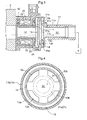
- Fig. 2 is a section view of the fluid control valve 1 according to the present invention.
- the housing of this fluid control valve 1 is formed by securing a first housing 11 to a second housing 12.
- the second housing 12 houses therein a solenoid 20.
- the solenoid 20 includes a core 21, a bobbin 22, a coil 23 and a yoke 24.
- the core 21 is comprised of a ferromagnetic body of iron, magnetic steel or the like and has a hollow tubular shape, i.e. a cylindrical shape as shown in Fig. 2 .
- This hollow portion of the core 21 constitutes an inflow channel 31 for introducing cooling water to the inside of the fluid control valve 1, to which inflow channel 31 there is connected the flow channel from the engine 2. Further, this core 21 is configured to function as a "valve seat" as will be described later.
- the bobbin 22 is provided with a length of coil 23 wound around it with the core 21 being inserted therein.
- the yoke 24 is provided radially outwardly of the bobbin 22.
- the fluid control valve 1 of the present invention remains under the closed state in the absence of development of hydraulic pressure in the cooling water (initial state) and the solenoid 20 is maintained under the closed state even after development of hydraulic pressure of the cooling water.
- the components constituting the solenoid 20 such as the coil 23 can be formed small.
- the electric resistance becomes higher. Therefore, in order to equate the magnetic force of the coil 23 under a high temperature condition with the magnetic force of the coil 23 under a low temperature condition, it is necessary either to increase the current to be applied to the coil 23 under the high temperature condition or to increase the number of turns of the coil 23 having a high resistance.
- these arrangements are not desirable as they invite increase of power consumption or physical enlargement of the solenoid 20.
- coating is not provided to at least the inner wall surface (the wall surface of the inflow channel 31) of the core 21 which is coated at the remaining portion thereof with a resin or the like so that the material forming the core 21 body may come into contact with the cooling water.
- the first housing 11 is formed as a first hollow tubular portion 11a and a second tubular portion 11 b having a greater radius than the first tubular portion 11 a are integrated together with the respective axes thereof being aligned.
- the second tubular portion 11 b will be secured to the second housing 12.
- the hollow portion of the first tubular portion 11a constitutes an outflow channel 32 for discharging the cooling water to the outside of the fluid control valve 1 and this outflow channel 32 is connected to the inflow channel to the thermostat valve 5.
- the plunger 13 as a valve body formed of a magnetic material such as iron and an urging spring 14 for urging the plunger 13 toward the core 21.
- the face of the plunger 13 on the side of the core 21 (this face will be referred to as "the bottom face” hereinafter) is polished in order to obtain higher degree of firm contact with the core 21.
- the plunger 13 as a valve body comes into contact with the plunger 13 side end face of the core 21 as a valve seat 21 a, so that the fluid control valve 1 is set under a closed state (see Fig. 2 ).
- the plunger 13 in this embodiment includes four flow channels 13b radially outward of the radius of the core 21. Therefore, when the plunger 13 is moved in the direction away from the core 21 due to the hydraulic pressure of cooling water, the plunger 13 will be located at the position spaced by a predetermined distance from the inner wall face of the second tubular portion 11 b as described above, so that communication is established between the inflow channel 31 and the outflow channel 32 via the flow channels 13b (establishment of a valve opened state). Namely, in association with the movement of the plunger 13 in the direction away from the core 21, the fluid control valve 1 is rendered into the valve opened state.
- the fluid control valve 1 can be formed compact.
- the four flow channels 13b are formed equidistantly on a same circle located more radially outward than the core 21, as seen in the plan view. Therefore, the hydraulic pressure of cooling water can be applied uniformly to the bottom face (the core 21 side face) of the plunger 13, whereby the posture of the plunger 13 can be stable even in the presence if any of pulsatory variations in the hydraulic pressure of cooling water. As a result, it is possible to restrict occurrence of frictional wear of a guide portion 13a of the plunger 13 and generation of noise due to contact between the plunger 13 and the core 21.
- the flow channels 13b are formed of holes. Instead, these channels may be formed of cutouts. Further, the size of the cross sectional area of the flow channel 13b may vary appropriately, depending on e.g. the amount of cooling water, the intensity of the magnetic force applied to the plunger 13. Moreover, the number of flow channels 13b and the cross sectional shape thereof may too vary as needed.
- the magnetism generated by the solenoid 20 passes from the core 21 to the yoke 24 via the plunger 13. Taking this into consideration, it is desired that the cross sectional area through which the magnetism (magnetic flux) passes be substantially constant or progressively increase in the order from the core 21, the plunger 13 and the yoke 24.
- the size of the flow channel 13b be determined in such a manner as follows. Namely, the cross sectional area of the portion of the plunger 13 except for the portions of the flow channels 13b at a circumferential position on a circle having the smallest radius of the circles centered about the axis of the plunger 13 and extending on the flow channels 13b should preferably be greater than the cross sectional area (the area of contact between the core 21 and the plunger 13) as seen in the axial direction of the core 21.
- the cross sectional area of the portion of the plunger 13 except for the portions of the flow channels 13b at a circumferential position refers to the cross sectional area having the value obtained by multiplying the circumferential length of the circle excluding the lengths of the portions that pass inside the flow channels 13b with the thickness of the plunger 13.
- the yoke 24 is disposed to face the plunger 13 in the axial direction of the plunger 13, but no contact occurs between the plunger 13 and the yoke 24. Therefore, in view of the passage of magnetism, it is preferred that the portion of the plunger 13 which portion faces the yoke 24 be formed larger. For this reason, in the instant embodiment, the aperture shape of the flow channel 13b is determined such that the area of the portion of the plunger 13 facing the yoke 24 is greater than the area of the portion of the plunger 13 facing the core 21.
- Fig. 5 is an enlarged section view of the fluid control valve 1 according to the instant embodiment.
- the guide portion 13a disposed erect in the direction opposite to the solenoid 20 (the upper direction in the illustration).
- This guide portion 13a is in contact with the inner wall of the first housing 11 or the second housing 12. Therefore, when the plunger 13 moves, the guide portion 13 is placed in contact with the inner wall of the first housing 11 or the second housing 12. With this, the posture of the plunger 13 during its movement is stabilized, thereby to avoid malfunction of a valve stick or the like.
- the outer circumferential face of the plunger 13a may be configured to function as the guide portion 13a.
- the plunger 13 side end face of the core 21 is caused to project more toward the plunger 13 than the plunger 13 side end face of the yoke 24.
- the plunger 13 comes into contact with the core 21 only. That is, in this arrangement, only the plunger 13 side end face of the core 21 constitutes the valve seat 21a.
- the smaller pressure receiving face means reduction in the force received from cooling water and the possibility of decreasing the magnetic force to resist it. That is, since the reduction in the pressure receiving area from cooling water allows reduction in the number of turns of the coil 23, the above arrangement can contribute to compactization of the fluid control valve 1.
- the plunger 13 side end face of the core 21 may be located at a substantially same position as the plunger 13 side end face of the yoke 24 and a convex portion 13c projecting toward the core 21 may be formed in the bottom face of the plunger 13.
- a convex portion 13c projecting toward the core 21 may be formed in the bottom face of the plunger 13.
- This convex portion 13c has a cross sectional area greater at least than the cross sectional area of the inflow channel 31.
- the convex portion 13c is formed like a disk centering about the axis of the core 21 and having a radius substantially equal to the radius of the core 21, it becomes possible to reduce the pressure receiving area from cooling water, so that a greater degree of firm contact can be obtained with a smaller amount of magnetic force.
- the solenoid 20 can be formed compact, advantageously.
- the convex portion 13c may be formed in the bottom face of the plunger 13.
- the plunger 13 side end face of the core 21 is configured to constitute the valve seat 21 a.
- a valve seat may be provided separately in the plunger 13 side end face of the core 21. In such case, in this valve seat too, there will be formed a flow channel communicated with the inflow channel formed in the core 21.
- the present invention is applicable to a fluid control valve for controlling the flow of fluid such as cooling water or oil in a vehicle.
Landscapes
- Engineering & Computer Science (AREA)
- General Engineering & Computer Science (AREA)
- Mechanical Engineering (AREA)
- Chemical & Material Sciences (AREA)
- Combustion & Propulsion (AREA)
- Magnetically Actuated Valves (AREA)
Abstract
Description
- The present invention relates to a fluid control valve, more particularly to a fluid control valve for controlling the flow of cooling water in a vehicle.
- Conventionally, a vehicle mounts a cooling device that circulates a cooling water for cooling an internal combustion engine such as an engine, between the engine or the like and a radiator. And, such cooling device is sometimes provided with a fluid control valve for controlling the flow of the cooling water for the sake of controlling the temperature of cooling water.
- For instance,
Patent Document 1 discloses an electronically controlled thermostat as an example of such fluid control valve. This electronically controlled thermostat disclosed inPatent Document 1 is provided with a thermo element having a piston for opening/closing a valve body, so that with transfer of the temperature of the cooling water at the exit of the radiator to an element temperature-sensitive portion of the thermo element, opening/closing of the valve body is realized. Thus, the arrangement can realize opening/closing of the valve body without provision of a sensor or the like for detecting the temperature of cooling water. - However, with the electronically controlled thermostat disclosed in
Patent Document 1, the heat of cooling water heated by the engine is discharged from a heat-sensing chamber, so that there is the possibility of sufficient heat being not transferred to the element temperature-sensitive portion. In such case, delay will occur in the opening of the valve body, disadvantageously. - In order to solve the above problem, it is conceivable to employ an electromagnetic valve disclosed in
Patent Document 2 as the fluid control valve. With the electromagnetic valve ofPatent Document 2, a movable core is mounted inside a coil. As the movable core is moved in response to electric power supply to the coil, opening/closing of the valve is controlled. Therefore, with an arrangement for controlling the power supply to the coil according to the temperature of the fluid, there can be provided a fluid control valve having good temperature followability or sensitivity for a change in the temperature of the fluid. - Patent Document 1: Japanese Unexamined Patent Application Publication No.
2003-328753
Patent Document 2: Japanese Unexamined Patent Application Publication No.2002-340219 - As described above, with use of the electromagnetic valve disclosed in
Patent Document 2, it is possible to provide a fluid control valve having good followability. However, when an electric current is applied to the coil for magnetic force generation, heat will be generated from the coil, thus causing a problem of discharging this heat. If a cooling device is provided separately in order to discharge the heat from the coil, this will invite physical enlargement and weight increase of the fluid control valve, disadvantageously. - Further, in the case of using the electromagnetic value of
Patent Document 2 as a fluid control valve for a large amount of fluid such as cooling water for cooling an engine or the like, the valve opening/closing operation needs to be effected against a significant hydraulic pressure of the fluid. And, high sealing performance will be required also. This could be realized by way of increase of the magnetic force. In such case; however, there arises the need of enlarging the other components such as the coil. Hence, this will again invite physical enlargement and weight increase of the fluid control valve, disadvantageously. - The present invention has been made in view of the above-described problem and its object is to provide a fluid control valve that can be used for a large amount of fluid without needing enlargement of the valve.
- For solving the above-noted problem, a fluid control valve incorporated in a circulatory flow passageway for circulating fluid between an engine and a heat exchanger, the fluid control valve comprising:
- an inflow channel for introducing the fluid;
- an outflow channel for discharging the fluid;
- a valve seat;
- a valve body for blocking/allowing communication between the inflow channel and the outflow channel in association with a movement thereof into contact with or away from the valve seat; and
- a solenoid configured to apply a magnetic force to the valve body, the magnetic force being generated in response to supply of electric power to the solenoid;
- wherein the inflow channel is formed through a core of the solenoid so that the core and the fluid come into contact with each other in the inflow channel.
- In general, as the temperature of the coil of the solenoid rises, the electric resistance becomes higher. Therefore, in order for a solenoid under a high temperature condition to generate a same intensity of magnetic force as that of the solenoid under a low temperature condition, it will be needed either to increase the current to be applied thereto or to increase the number of turns of the coil. However, these arrangements are not desirable as they invite increase of power consumption or enlargement of the fluid control valve. For this reason, according to the inventive arrangement described above, an inflow channel for introducing fluid to the interior of the fluid control valve is formed through a core of the solenoid so that the core comes into contact with the fluid within the inflow channel. This facilitates escape of heat generated from the coil into the fluid, so that temperature rise of the coil can be effectively restricted. Therefore, it is possible to generate the magnetic force needed for controlling the valve body without inviting increase of power consumption or enlargement of the fluid control valve.
- According to one preferred embodiment of the fluid control valve of the present invention, the valve seat is comprised of the core.
- With this arrangement, the inflow channel is formed through the core of the solenoid, which core constitutes a valve seat. Accordingly, when the valve body blocks communication between the inflow channel and the outflow channel, the valve body comes into contact with the core alone. Thus, the sealing performance can be improved. Moreover, as the pressure receiving area of the fluid is formed smaller, it is possible to decrease the magnetic force to be applied to the valve body. Since the amount of magnetic force depends on the number of turns of the coil of the solenoid and the amount of current, the possibility of decrease of magnetic force can contribute to power consumption saving and compactization of the fluid control valve.
- According to one preferred embodiment of the fluid control valve of the present invention, the solenoid includes a yoke disposed radially outward as seen in an axial direction of the core; and an end face of the core on the side of the valve body protrudes more toward the valve body than an end face of the yoke on the side of the valve body. According to another preferred embodiment of the present invention of the fluid control valve of the present invention, the core side end face of the valve body includes a convex portion which comes into contact with the core.
- With these arrangements, the valve body contact only the core, and the core can function as a valve seat.
- According to another preferred embodiment of the fluid control valve of the present invention, the valve body includes a flow channel more radially outwards than the valve seat as seen in the axial direction of the core.
- According to another preferred embodiment of the fluid control valve of the present invention, in response to electric power supply to the solenoid, the solenoid generates a magnetic flux which affects the core and the valve body; and the core and the valve body are cooled as coming into direct contact with the fluid.
- With the fluid control valve according to the present invention, there is no need for enlarging the device even when it is applied to a large amount of fluid.
-
- [
Fig. 1 ] is a diagram showing an engine cooling system using a fluid control valve according to the present invention, - [
Fig. 2 ] is a section view showing the fluid control valve of the present invention under a closed state thereof, - [
Fig. 3 ] is a section view showing the fluid control valve of the present invention under an opened state thereof, - [
Fig. 4 ] is a plan view of a plunger of the fluid control valve of the present invention, - [
Fig. 5 ] is an enlarged section view of the fluid control valve according to the present invention, and - [
Fig. 6 ] is an enlarged section view of an alternative arrangement of the fluid control valve according to the present invention. - Next, with reference to the accompanying drawings, the fluid control valve according to the present invention will be described.
Fig. 1 is a diagram showing an engine cooling system using the fluid control valve according to the present invention. Anengine 2 has two routes of outflow passageway for cooling water (fluid), one being connected to aradiator 3, the other being connected to a heater core 6 (an example of a "heat exchanger" in the invention). - The outflow channel from the
radiator 3 is connected to athermostat valve 5. The outflow channel from thethermostat valve 5 is connected to awater pump 4. Further, the outflow channel from thewater pump 4 is connected to an inflow channel to theengine 2. With these flow channels, cooling water heated by theengine 2 is introduced to theradiator 3 and cooled therein, and this cooled water is caused to flow through thethermostat valve 5 and thewater pump 4 back to theengine 2. - On the other hand, the flow channel from the
engine 2 to theheater core 6 incorporates afluid control valve 1. The outflow channel from thecore heater 6 is connected to another inflow channel to thethermostat valve 5. With these flow channels, the water heated by theengine 2 is introduced to theheater core 6 via thefluid control valve 1, so that theheater core 6 heats air present inside the vehicle, and the resultant cooled water is then caused to flow back to theengine 2 via thethermostat valve 5 and thewater pump 4. - The
fluid control valve 1 according to the present invention is incorporated in the flow channel from theengine 2 to theheater core 6 as described above and used for controlling outflow of the cooling water to theheater core 6. The inventivefluid control valve 1 is closed in the absence of hydraulic pressure developed in the cooling water and is opened in response to hydraulic pressure developed in the cooling water. Thefluid control valve 1 is kept under the closed state with electric power supply to thefluid control valve 1. More particularly, the fluid control valve functions as follows. - Before the engine is started in response to a driver's operation of an ignition key or the like, namely, before the
water pump 4 is activated, electric power is supplied to thefluid control valve 1. As described hereinbefore, thefluid control valve 1 is kept under the closed state in the absence of hydraulic pressure developed in the cooling water. But, with electric power supply to thevalve 1 under the closed state, this closed state can be maintained even if there develops a hydraulic pressure thereafter. With this, no cooling water will flow to theheater core 6, so that the cooling water can be heated more speedily. Further, when the temperature of the cooling water is low, thethermostat valve 5 too is closed, so that no cooling water will flow to theradiator 3 either, so that the temperature of the cooling water can be raised even more speedily. As the temperature of the cooling water is raised speedily as described above, the temperature rise of engine oil or the like too can be sped up, thus contributing to improvement in fuel consumption efficiency. - Thereafter, when the temperature of the cooling water reaches a predetermined temperature (completion of warming-up operation), the electric power supply to the
fluid control valve 1 is stopped. With this, the hydraulic pressure of the cooling water renders thefluid control valve 1 into the opened state, so that cooling water flows out toward theheater core 6. -
Fig. 2 is a section view of thefluid control valve 1 according to the present invention. The housing of thisfluid control valve 1 is formed by securing afirst housing 11 to asecond housing 12. Thesecond housing 12 houses therein asolenoid 20. - The
solenoid 20 includes a core 21, abobbin 22, acoil 23 and ayoke 24. Thecore 21 is comprised of a ferromagnetic body of iron, magnetic steel or the like and has a hollow tubular shape, i.e. a cylindrical shape as shown inFig. 2 . This hollow portion of thecore 21 constitutes aninflow channel 31 for introducing cooling water to the inside of thefluid control valve 1, to whichinflow channel 31 there is connected the flow channel from theengine 2. Further, thiscore 21 is configured to function as a "valve seat" as will be described later. - Further, the
bobbin 22 is provided with a length ofcoil 23 wound around it with the core 21 being inserted therein. Theyoke 24 is provided radially outwardly of thebobbin 22. As the material for forming theyoke 24, iron, magnetic steel or the like is employed. - In response to electric power supply to this
coil 23 from a power source (not shown), magnetism (magnetic flux) is developed in thesolenoid 20. The generated magnetism passes from the core 21 to theyoke 24 via aplunger 13. Therefore, as the plunger 13 (to be described later) acting as a "valve body" is attracted to the core 21 constituting a "valve seat", thefluid control valve 1 can be maintained under the closed state (the state of blocked communication between aninflow channel 31 and an outflow channel 32) even if a hydraulic pressure is developed in the cooling water. Incidentally, thefluid control valve 1 of the present invention remains under the closed state in the absence of development of hydraulic pressure in the cooling water (initial state) and thesolenoid 20 is maintained under the closed state even after development of hydraulic pressure of the cooling water. Hence, as compared with a fluid control valve which is shifted from an opened state to a closed state by the magnetic force of thesolenoid 20, the components constituting thesolenoid 20 such as thecoil 23 can be formed small. - In general, in accordance as the temperature of the
coil 23 rises, the electric resistance becomes higher. Therefore, in order to equate the magnetic force of thecoil 23 under a high temperature condition with the magnetic force of thecoil 23 under a low temperature condition, it is necessary either to increase the current to be applied to thecoil 23 under the high temperature condition or to increase the number of turns of thecoil 23 having a high resistance. However, these arrangements are not desirable as they invite increase of power consumption or physical enlargement of thesolenoid 20. As a solution to these problems, it is conceivable to cool thecoil 23. Then, in the instant embodiment, theinflow channel 31 is formed inside thecore 21. Moreover, coating is not provided to at least the inner wall surface (the wall surface of the inflow channel 31) of the core 21 which is coated at the remaining portion thereof with a resin or the like so that the material forming the core 21 body may come into contact with the cooling water. With this arrangement, heat generated at the time of power supply to thecoil 23 may be readily transferred via thecore 21 to the cooling water flowing in theinflow channel 31, whereby rise of the temperature of thecoil 23 can be effectively prevented. - The
first housing 11 is formed as a firsthollow tubular portion 11a and a secondtubular portion 11 b having a greater radius than the firsttubular portion 11 a are integrated together with the respective axes thereof being aligned. When thefirst housing 11 and thesecond housing 12 are to be secured to each other, the secondtubular portion 11 b will be secured to thesecond housing 12. Incidentally, the hollow portion of the firsttubular portion 11a constitutes anoutflow channel 32 for discharging the cooling water to the outside of thefluid control valve 1 and thisoutflow channel 32 is connected to the inflow channel to thethermostat valve 5. - Further, inside (within the hollow portion) of the second
tubular portion 11 b, there are mounted theplunger 13 as a valve body formed of a magnetic material such as iron and an urgingspring 14 for urging theplunger 13 toward thecore 21. As theplunger 13 functions as a valve body, the face of theplunger 13 on the side of the core 21 (this face will be referred to as "the bottom face" hereinafter) is polished in order to obtain higher degree of firm contact with thecore 21. When the hydraulic pressure of the cooling water is low, theplunger 13 as a valve body comes into contact with theplunger 13 side end face of the core 21 as avalve seat 21 a, so that thefluid control valve 1 is set under a closed state (seeFig. 2 ). Incidentally, when thefluid control valve 1 is used under a posture with itscore 21 being positioned on the upper side, theplunger 13 and the core 21 will contact each other due to the weight of theplunger 13. Hence, the urgingspring 14 can be omitted in that case. - On the other hand, when the hydraulic pressure of cooling water overwhelms the urging force of the urging
spring 14, this hydraulic pressure causes theplunger 13 to move in the direction away from thecore 21, thus releasing the contact between thisplunger 13 and thecore 21. In the course of this, thefirst housing 11 side face of theplunger 13 comes into contact with amovement restricting portion 11c projecting toward theplunger 13 whichportion 11c is provided in the inner wall face of the secondtubular portion 11b facing theplunger 13. With this, the upper face of theplunger 13 is brought into a position at which the face does not contact the inner wall face of the secondtubular portion 11 b, but keeps a predetermined distance relative thereto. - The
plunger 13 in this embodiment, as shown inFig. 4 , includes fourflow channels 13b radially outward of the radius of thecore 21. Therefore, when theplunger 13 is moved in the direction away from thecore 21 due to the hydraulic pressure of cooling water, theplunger 13 will be located at the position spaced by a predetermined distance from the inner wall face of the secondtubular portion 11 b as described above, so that communication is established between theinflow channel 31 and theoutflow channel 32 via theflow channels 13b (establishment of a valve opened state). Namely, in association with the movement of theplunger 13 in the direction away from thecore 21, thefluid control valve 1 is rendered into the valve opened state. - As described above, by forming the
flow channels 13b in theplunger 13 as the valve body, it becomes unnecessary to provide any flow channels radially outwardly of theplunger 13. As a result, thefluid control valve 1 can be formed compact. - Further, as shown in
Fig. 4 , the fourflow channels 13b are formed equidistantly on a same circle located more radially outward than the core 21, as seen in the plan view. Therefore, the hydraulic pressure of cooling water can be applied uniformly to the bottom face (the core 21 side face) of theplunger 13, whereby the posture of theplunger 13 can be stable even in the presence if any of pulsatory variations in the hydraulic pressure of cooling water. As a result, it is possible to restrict occurrence of frictional wear of aguide portion 13a of theplunger 13 and generation of noise due to contact between theplunger 13 and thecore 21. - Incidentally, in the instant embodiment, the
flow channels 13b are formed of holes. Instead, these channels may be formed of cutouts. Further, the size of the cross sectional area of theflow channel 13b may vary appropriately, depending on e.g. the amount of cooling water, the intensity of the magnetic force applied to theplunger 13. Moreover, the number offlow channels 13b and the cross sectional shape thereof may too vary as needed. Incidentally, as described above, the magnetism generated by thesolenoid 20 passes from the core 21 to theyoke 24 via theplunger 13. Taking this into consideration, it is desired that the cross sectional area through which the magnetism (magnetic flux) passes be substantially constant or progressively increase in the order from thecore 21, theplunger 13 and theyoke 24. - Therefore, in view of the fact that the magnetism passes through the
core 21 along the axial direction of thecore 21 and flows through theplunger 13 along the outer radial direction of theplunger 13, it is preferred that the size of theflow channel 13b be determined in such a manner as follows. Namely, the cross sectional area of the portion of theplunger 13 except for the portions of theflow channels 13b at a circumferential position on a circle having the smallest radius of the circles centered about the axis of theplunger 13 and extending on theflow channels 13b should preferably be greater than the cross sectional area (the area of contact between the core 21 and the plunger 13) as seen in the axial direction of thecore 21. In the above, "the cross sectional area of the portion of theplunger 13 except for the portions of theflow channels 13b at a circumferential position" refers to the cross sectional area having the value obtained by multiplying the circumferential length of the circle excluding the lengths of the portions that pass inside theflow channels 13b with the thickness of theplunger 13. - Further, in the instant embodiment, the
yoke 24 is disposed to face theplunger 13 in the axial direction of theplunger 13, but no contact occurs between theplunger 13 and theyoke 24. Therefore, in view of the passage of magnetism, it is preferred that the portion of theplunger 13 which portion faces theyoke 24 be formed larger. For this reason, in the instant embodiment, the aperture shape of theflow channel 13b is determined such that the area of the portion of theplunger 13 facing theyoke 24 is greater than the area of the portion of theplunger 13 facing thecore 21. - With the above-described arrangement for improving the efficiency of passage of magnetism, it is possible to reduce the magnetic force generated by the
solenoid 20, thus contributing to the reduction in the current applied to thesolenoid 20 and to compactization through reduction in the number of turns of the coil. -
Fig. 5 is an enlarged section view of thefluid control valve 1 according to the instant embodiment. As shown, in the outer circumference of theplunger 13, there is formed theguide portion 13a disposed erect in the direction opposite to the solenoid 20 (the upper direction in the illustration). Thisguide portion 13a is in contact with the inner wall of thefirst housing 11 or thesecond housing 12. Therefore, when theplunger 13 moves, theguide portion 13 is placed in contact with the inner wall of thefirst housing 11 or thesecond housing 12. With this, the posture of theplunger 13 during its movement is stabilized, thereby to avoid malfunction of a valve stick or the like. Incidentally, it is not essentially required to dispose theguide portion 13a erect in the outer circumference of theplunger 13. Instead, the outer circumferential face of theplunger 13a may be configured to function as theguide portion 13a. - Further, as shown in
Fig. 5 , in the instant embodiment, theplunger 13 side end face of thecore 21 is caused to project more toward theplunger 13 than theplunger 13 side end face of theyoke 24. With this arrangement, when theplunger 13 is urged or attracted to the core 21 side due to the urging force of the urgingspring 14 or the magnetic force of thesolenoid 20, theplunger 13 comes into contact with the core 21 only. That is, in this arrangement, only theplunger 13 side end face of thecore 21 constitutes thevalve seat 21a. With this, the sealing performance can be improved and the pressure receiving area from cooling water can be formed small. The smaller pressure receiving face means reduction in the force received from cooling water and the possibility of decreasing the magnetic force to resist it. That is, since the reduction in the pressure receiving area from cooling water allows reduction in the number of turns of thecoil 23, the above arrangement can contribute to compactization of thefluid control valve 1. - Further, as shown in
Fig. 6 , theplunger 13 side end face of the core 21 may be located at a substantially same position as theplunger 13 side end face of theyoke 24 and aconvex portion 13c projecting toward the core 21 may be formed in the bottom face of theplunger 13. With such arrangement as above too, like the arrangement shown inFig. 5 , only theplunger 13 side end face of the core 21 will constitute thevalve seat 21a, so that the arrangement can contribute to improvement in the sealing performance and compactization of the fluid control valve. - This
convex portion 13c has a cross sectional area greater at least than the cross sectional area of theinflow channel 31. In particular, if theconvex portion 13c is formed like a disk centering about the axis of thecore 21 and having a radius substantially equal to the radius of the core 21, it becomes possible to reduce the pressure receiving area from cooling water, so that a greater degree of firm contact can be obtained with a smaller amount of magnetic force. As a result, thesolenoid 20 can be formed compact, advantageously. - Further, with the positional relationship between the core 21 and the
yoke 24 may be set as shown inFig. 5 , theconvex portion 13c may be formed in the bottom face of theplunger 13. - In the foregoing embodiment, the
plunger 13 side end face of thecore 21 is configured to constitute thevalve seat 21 a. Instead, a valve seat may be provided separately in theplunger 13 side end face of thecore 21. In such case, in this valve seat too, there will be formed a flow channel communicated with the inflow channel formed in thecore 21. - The present invention is applicable to a fluid control valve for controlling the flow of fluid such as cooling water or oil in a vehicle.
-
- 1: fluid control valve
- 2: engine
- 6: heater core (heat exchanger)
- 13: plunger (valve body)
- 13c: convex portion
- 20: solenoid
- 21: core
- 21 a: valve seat
- 24: yoke
- 31: inflow channel
- 32: outflow channel
Claims (6)
- A fluid control valve incorporated in a circulatory flow passageway for circulating fluid between an engine and a heat exchanger, the fluid control valve comprising:an inflow channel for introducing the fluid;an outflow channel for discharging the fluid;a valve seat;a valve body for blocking/allowing communication between the inflow channel and the outflow channel in association with a movement thereof into contact with or away from the valve seat; anda solenoid configured to apply a magnetic force to the valve body, the magnetic force being generated in response to supply of electric power to the solenoid;wherein the inflow channel is formed through a core of the solenoid so that the core and the fluid come into contact with each other in the inflow channel.
- A fluid control valve according to claim 1, wherein the valve seat is comprised of the core.
- A fluid control valve according to claim 1 or 2, wherein
the solenoid includes a yoke disposed radially outward as seen in an axial direction of the core; and
an end face of the core on the side of the valve body protrudes more toward the valve body than an end face of the yoke on the side of the valve body. - A fluid control valve according to claim 1 or 2, wherein the core side end face of the valve body includes a convex portion which comes into contact with the core.
- A fluid control valve according to any one of claims 1-4, wherein the valve body includes a flow channel more radially outwards than the valve seat as seen in the axial direction of the core.
- A fluid control valve according to any one of claims 1-5, wherein in response to electric power supply to the solenoid, the solenoid generates a magnetic flux which affects the core and the valve body; and
the core and the valve body are cooled as coming into direct contact with the fluid.
Applications Claiming Priority (3)
| Application Number | Priority Date | Filing Date | Title |
|---|---|---|---|
| JP2010246377A JP5574180B2 (en) | 2010-11-02 | 2010-11-02 | Fluid control valve |
| JP2010246378A JP5614585B2 (en) | 2010-11-02 | 2010-11-02 | Fluid control valve |
| PCT/JP2011/073413 WO2012060188A1 (en) | 2010-11-02 | 2011-10-12 | Fluid control valve |
Publications (3)
| Publication Number | Publication Date |
|---|---|
| EP2613072A1 true EP2613072A1 (en) | 2013-07-10 |
| EP2613072A4 EP2613072A4 (en) | 2014-01-08 |
| EP2613072B1 EP2613072B1 (en) | 2018-06-27 |
Family
ID=46024307
Family Applications (1)
| Application Number | Title | Priority Date | Filing Date |
|---|---|---|---|
| EP11837839.7A Active EP2613072B1 (en) | 2010-11-02 | 2011-10-12 | Fluid control valve |
Country Status (5)
| Country | Link |
|---|---|
| US (1) | US9027905B2 (en) |
| EP (1) | EP2613072B1 (en) |
| CN (1) | CN103097790B (en) |
| BR (1) | BR112013005526B1 (en) |
| WO (1) | WO2012060188A1 (en) |
Families Citing this family (11)
| Publication number | Priority date | Publication date | Assignee | Title |
|---|---|---|---|---|
| WO2011132530A2 (en) | 2010-04-19 | 2011-10-27 | Aisin Seiki Kabushiki Kaisha | Vehicle coolant control valve |
| JP5257713B2 (en) * | 2011-02-10 | 2013-08-07 | アイシン精機株式会社 | Vehicle cooling system |
| JP6086201B2 (en) * | 2012-11-20 | 2017-03-01 | アイシン精機株式会社 | Fluid control valve |
| DE102016112235A1 (en) * | 2016-07-05 | 2018-01-11 | Dr. Ing. H.C. F. Porsche Aktiengesellschaft | Device for controlling the coolant flow in internal combustion engines |
| CN108343758B (en) * | 2017-01-24 | 2019-06-14 | 黄国洪 | Fluid Control Valve |
| CN207394082U (en) * | 2017-02-14 | 2018-05-22 | 爱信精机株式会社 | Control valve for fluids |
| JP7358038B2 (en) * | 2018-07-18 | 2023-10-10 | 株式会社ミクニ | solenoid valve |
| CN209164045U (en) * | 2018-11-19 | 2019-07-26 | 浙江锐韦机电科技有限公司 | Integrated pump valve mechanism |
| JP7107260B2 (en) * | 2019-03-14 | 2022-07-27 | 浜名湖電装株式会社 | fluid control valve |
| JP7107261B2 (en) * | 2019-03-14 | 2022-07-27 | 浜名湖電装株式会社 | fluid control valve |
| GB2604371B (en) | 2021-03-03 | 2023-12-06 | Equinor Energy As | Improved inflow control device |
Family Cites Families (12)
| Publication number | Priority date | Publication date | Assignee | Title |
|---|---|---|---|---|
| DE1273945B (en) * | 1965-03-11 | 1968-07-25 | Buehler Ag Geb | Hydraulic pressure regulator with electromagnetic actuator |
| JPS5347026A (en) * | 1976-10-08 | 1978-04-27 | Hattori Zenichi | Highhspeed electroomagnetic valve |
| JPS5610563U (en) * | 1979-07-04 | 1981-01-29 | ||
| JPS57168017A (en) * | 1981-04-08 | 1982-10-16 | Nissan Motor Co Ltd | Control device of cooling in water-cooled internal combustion engine |
| DE3610122A1 (en) * | 1986-03-26 | 1987-10-08 | Bosch Gmbh Robert | MAGNETIC VALVE |
| DE3920893A1 (en) * | 1989-06-26 | 1991-01-10 | Bayerische Motoren Werke Ag | Magnetic valve for heating medium flow of vehicle - provides linear flow with valve and seat supported at housing across pressure spring |
| JP2002340219A (en) | 2001-05-16 | 2002-11-27 | Aisin Seiki Co Ltd | solenoid valve |
| JP2003328753A (en) | 2002-05-10 | 2003-11-19 | Nippon Thermostat Co Ltd | Electronic thermostat |
| JP3706363B2 (en) | 2002-11-12 | 2005-10-12 | 三菱電機株式会社 | solenoid valve |
| US8991124B2 (en) | 2008-10-17 | 2015-03-31 | Schöck Bauteile GmbH | Concrete material, construction element for a thermal insulation, and brick-shaped thermally insulating element, each using the concrete material |
| CN201521701U (en) * | 2009-06-09 | 2010-07-07 | 奚勇 | Magnetic valve for fluid control |
| WO2011132530A2 (en) | 2010-04-19 | 2011-10-27 | Aisin Seiki Kabushiki Kaisha | Vehicle coolant control valve |
-
2011
- 2011-10-12 WO PCT/JP2011/073413 patent/WO2012060188A1/en not_active Ceased
- 2011-10-12 CN CN201180043102.6A patent/CN103097790B/en active Active
- 2011-10-12 BR BR112013005526-0A patent/BR112013005526B1/en active IP Right Grant
- 2011-10-12 US US13/821,358 patent/US9027905B2/en active Active
- 2011-10-12 EP EP11837839.7A patent/EP2613072B1/en active Active
Also Published As
| Publication number | Publication date |
|---|---|
| EP2613072A4 (en) | 2014-01-08 |
| US20130161548A1 (en) | 2013-06-27 |
| CN103097790A (en) | 2013-05-08 |
| CN103097790B (en) | 2015-02-25 |
| BR112013005526B1 (en) | 2021-06-22 |
| US9027905B2 (en) | 2015-05-12 |
| EP2613072B1 (en) | 2018-06-27 |
| WO2012060188A1 (en) | 2012-05-10 |
| BR112013005526A2 (en) | 2020-09-01 |
Similar Documents
| Publication | Publication Date | Title |
|---|---|---|
| EP2613072B1 (en) | Fluid control valve | |
| CN102812220B (en) | Vehicle coolant control valve | |
| US9133952B2 (en) | Thermostatic bypass valve with a unique valve seat | |
| JP6086201B2 (en) | Fluid control valve | |
| US10273868B2 (en) | Fluid control valve | |
| CN110630729B (en) | Temperature regulating valve | |
| CN106415096B (en) | Solenoid valve and internal combustion engine cooling system with solenoid valve | |
| CN108350890B (en) | Control device for a mechanically controllable coolant pump of an internal combustion engine | |
| JP2004263587A (en) | Vehicle cooling system | |
| KR20170044200A (en) | Electromagnetically actuatable expansion valve | |
| EP2314902A2 (en) | Fluid control valve | |
| CN115066543B (en) | Cooling water temperature control device | |
| JP5574180B2 (en) | Fluid control valve | |
| US9359933B2 (en) | Thermostatic valve assembly | |
| RU2723652C2 (en) | Electromagnetic switching valve | |
| JP5614585B2 (en) | Fluid control valve | |
| JP6442880B2 (en) | Control valve | |
| JP5618141B2 (en) | Fluid control valve | |
| JP6972776B2 (en) | Fluid control valve | |
| JP2005233044A (en) | Coolant pump | |
| US6129287A (en) | Viscous fluid type heat generating apparatus | |
| JP2004132242A (en) | Engine cooling water control valve | |
| CN116917603A (en) | Constant temperature device | |
| KR20060089041A (en) | Thermostat of vehicle | |
| JP2011153700A (en) | Fluid control valve |
Legal Events
| Date | Code | Title | Description |
|---|---|---|---|
| PUAI | Public reference made under article 153(3) epc to a published international application that has entered the european phase |
Free format text: ORIGINAL CODE: 0009012 |
|
| 17P | Request for examination filed |
Effective date: 20130307 |
|
| AK | Designated contracting states |
Kind code of ref document: A1 Designated state(s): AL AT BE BG CH CY CZ DE DK EE ES FI FR GB GR HR HU IE IS IT LI LT LU LV MC MK MT NL NO PL PT RO RS SE SI SK SM TR |
|
| A4 | Supplementary search report drawn up and despatched |
Effective date: 20131211 |
|
| RIC1 | Information provided on ipc code assigned before grant |
Ipc: F01P 7/16 20060101ALI20131205BHEP Ipc: F16K 31/06 20060101AFI20131205BHEP |
|
| DAX | Request for extension of the european patent (deleted) | ||
| 17Q | First examination report despatched |
Effective date: 20170725 |
|
| GRAP | Despatch of communication of intention to grant a patent |
Free format text: ORIGINAL CODE: EPIDOSNIGR1 |
|
| INTG | Intention to grant announced |
Effective date: 20180307 |
|
| GRAS | Grant fee paid |
Free format text: ORIGINAL CODE: EPIDOSNIGR3 |
|
| GRAA | (expected) grant |
Free format text: ORIGINAL CODE: 0009210 |
|
| AK | Designated contracting states |
Kind code of ref document: B1 Designated state(s): AL AT BE BG CH CY CZ DE DK EE ES FI FR GB GR HR HU IE IS IT LI LT LU LV MC MK MT NL NO PL PT RO RS SE SI SK SM TR |
|
| REG | Reference to a national code |
Ref country code: GB Ref legal event code: FG4D |
|
| REG | Reference to a national code |
Ref country code: AT Ref legal event code: REF Ref document number: 1012643 Country of ref document: AT Kind code of ref document: T Effective date: 20180715 |
|
| REG | Reference to a national code |
Ref country code: IE Ref legal event code: FG4D |
|
| REG | Reference to a national code |
Ref country code: DE Ref legal event code: R096 Ref document number: 602011049638 Country of ref document: DE |
|
| REG | Reference to a national code |
Ref country code: FR Ref legal event code: PLFP Year of fee payment: 8 |
|
| PG25 | Lapsed in a contracting state [announced via postgrant information from national office to epo] |
Ref country code: SE Free format text: LAPSE BECAUSE OF FAILURE TO SUBMIT A TRANSLATION OF THE DESCRIPTION OR TO PAY THE FEE WITHIN THE PRESCRIBED TIME-LIMIT Effective date: 20180627 Ref country code: LT Free format text: LAPSE BECAUSE OF FAILURE TO SUBMIT A TRANSLATION OF THE DESCRIPTION OR TO PAY THE FEE WITHIN THE PRESCRIBED TIME-LIMIT Effective date: 20180627 Ref country code: NO Free format text: LAPSE BECAUSE OF FAILURE TO SUBMIT A TRANSLATION OF THE DESCRIPTION OR TO PAY THE FEE WITHIN THE PRESCRIBED TIME-LIMIT Effective date: 20180927 Ref country code: BG Free format text: LAPSE BECAUSE OF FAILURE TO SUBMIT A TRANSLATION OF THE DESCRIPTION OR TO PAY THE FEE WITHIN THE PRESCRIBED TIME-LIMIT Effective date: 20180927 Ref country code: FI Free format text: LAPSE BECAUSE OF FAILURE TO SUBMIT A TRANSLATION OF THE DESCRIPTION OR TO PAY THE FEE WITHIN THE PRESCRIBED TIME-LIMIT Effective date: 20180627 |
|
| REG | Reference to a national code |
Ref country code: NL Ref legal event code: MP Effective date: 20180627 |
|
| REG | Reference to a national code |
Ref country code: LT Ref legal event code: MG4D |
|
| PG25 | Lapsed in a contracting state [announced via postgrant information from national office to epo] |
Ref country code: LV Free format text: LAPSE BECAUSE OF FAILURE TO SUBMIT A TRANSLATION OF THE DESCRIPTION OR TO PAY THE FEE WITHIN THE PRESCRIBED TIME-LIMIT Effective date: 20180627 Ref country code: RS Free format text: LAPSE BECAUSE OF FAILURE TO SUBMIT A TRANSLATION OF THE DESCRIPTION OR TO PAY THE FEE WITHIN THE PRESCRIBED TIME-LIMIT Effective date: 20180627 Ref country code: HR Free format text: LAPSE BECAUSE OF FAILURE TO SUBMIT A TRANSLATION OF THE DESCRIPTION OR TO PAY THE FEE WITHIN THE PRESCRIBED TIME-LIMIT Effective date: 20180627 Ref country code: GR Free format text: LAPSE BECAUSE OF FAILURE TO SUBMIT A TRANSLATION OF THE DESCRIPTION OR TO PAY THE FEE WITHIN THE PRESCRIBED TIME-LIMIT Effective date: 20180928 |
|
| REG | Reference to a national code |
Ref country code: AT Ref legal event code: MK05 Ref document number: 1012643 Country of ref document: AT Kind code of ref document: T Effective date: 20180627 |
|
| PG25 | Lapsed in a contracting state [announced via postgrant information from national office to epo] |
Ref country code: NL Free format text: LAPSE BECAUSE OF FAILURE TO SUBMIT A TRANSLATION OF THE DESCRIPTION OR TO PAY THE FEE WITHIN THE PRESCRIBED TIME-LIMIT Effective date: 20180627 |
|
| PG25 | Lapsed in a contracting state [announced via postgrant information from national office to epo] |
Ref country code: AT Free format text: LAPSE BECAUSE OF FAILURE TO SUBMIT A TRANSLATION OF THE DESCRIPTION OR TO PAY THE FEE WITHIN THE PRESCRIBED TIME-LIMIT Effective date: 20180627 Ref country code: IS Free format text: LAPSE BECAUSE OF FAILURE TO SUBMIT A TRANSLATION OF THE DESCRIPTION OR TO PAY THE FEE WITHIN THE PRESCRIBED TIME-LIMIT Effective date: 20181027 Ref country code: PL Free format text: LAPSE BECAUSE OF FAILURE TO SUBMIT A TRANSLATION OF THE DESCRIPTION OR TO PAY THE FEE WITHIN THE PRESCRIBED TIME-LIMIT Effective date: 20180627 Ref country code: EE Free format text: LAPSE BECAUSE OF FAILURE TO SUBMIT A TRANSLATION OF THE DESCRIPTION OR TO PAY THE FEE WITHIN THE PRESCRIBED TIME-LIMIT Effective date: 20180627 Ref country code: SK Free format text: LAPSE BECAUSE OF FAILURE TO SUBMIT A TRANSLATION OF THE DESCRIPTION OR TO PAY THE FEE WITHIN THE PRESCRIBED TIME-LIMIT Effective date: 20180627 Ref country code: RO Free format text: LAPSE BECAUSE OF FAILURE TO SUBMIT A TRANSLATION OF THE DESCRIPTION OR TO PAY THE FEE WITHIN THE PRESCRIBED TIME-LIMIT Effective date: 20180627 Ref country code: CZ Free format text: LAPSE BECAUSE OF FAILURE TO SUBMIT A TRANSLATION OF THE DESCRIPTION OR TO PAY THE FEE WITHIN THE PRESCRIBED TIME-LIMIT Effective date: 20180627 |
|
| PG25 | Lapsed in a contracting state [announced via postgrant information from national office to epo] |
Ref country code: IT Free format text: LAPSE BECAUSE OF FAILURE TO SUBMIT A TRANSLATION OF THE DESCRIPTION OR TO PAY THE FEE WITHIN THE PRESCRIBED TIME-LIMIT Effective date: 20180627 Ref country code: SM Free format text: LAPSE BECAUSE OF FAILURE TO SUBMIT A TRANSLATION OF THE DESCRIPTION OR TO PAY THE FEE WITHIN THE PRESCRIBED TIME-LIMIT Effective date: 20180627 Ref country code: ES Free format text: LAPSE BECAUSE OF FAILURE TO SUBMIT A TRANSLATION OF THE DESCRIPTION OR TO PAY THE FEE WITHIN THE PRESCRIBED TIME-LIMIT Effective date: 20180627 |
|
| REG | Reference to a national code |
Ref country code: DE Ref legal event code: R097 Ref document number: 602011049638 Country of ref document: DE |
|
| PLBE | No opposition filed within time limit |
Free format text: ORIGINAL CODE: 0009261 |
|
| STAA | Information on the status of an ep patent application or granted ep patent |
Free format text: STATUS: NO OPPOSITION FILED WITHIN TIME LIMIT |
|
| PG25 | Lapsed in a contracting state [announced via postgrant information from national office to epo] |
Ref country code: DK Free format text: LAPSE BECAUSE OF FAILURE TO SUBMIT A TRANSLATION OF THE DESCRIPTION OR TO PAY THE FEE WITHIN THE PRESCRIBED TIME-LIMIT Effective date: 20180627 |
|
| REG | Reference to a national code |
Ref country code: CH Ref legal event code: PL |
|
| 26N | No opposition filed |
Effective date: 20190328 |
|
| GBPC | Gb: european patent ceased through non-payment of renewal fee |
Effective date: 20181012 |
|
| REG | Reference to a national code |
Ref country code: BE Ref legal event code: MM Effective date: 20181031 |
|
| PG25 | Lapsed in a contracting state [announced via postgrant information from national office to epo] |
Ref country code: LU Free format text: LAPSE BECAUSE OF NON-PAYMENT OF DUE FEES Effective date: 20181012 Ref country code: MC Free format text: LAPSE BECAUSE OF FAILURE TO SUBMIT A TRANSLATION OF THE DESCRIPTION OR TO PAY THE FEE WITHIN THE PRESCRIBED TIME-LIMIT Effective date: 20180627 |
|
| REG | Reference to a national code |
Ref country code: IE Ref legal event code: MM4A |
|
| PG25 | Lapsed in a contracting state [announced via postgrant information from national office to epo] |
Ref country code: LI Free format text: LAPSE BECAUSE OF NON-PAYMENT OF DUE FEES Effective date: 20181031 Ref country code: SI Free format text: LAPSE BECAUSE OF FAILURE TO SUBMIT A TRANSLATION OF THE DESCRIPTION OR TO PAY THE FEE WITHIN THE PRESCRIBED TIME-LIMIT Effective date: 20180627 Ref country code: BE Free format text: LAPSE BECAUSE OF NON-PAYMENT OF DUE FEES Effective date: 20181031 Ref country code: CH Free format text: LAPSE BECAUSE OF NON-PAYMENT OF DUE FEES Effective date: 20181031 |
|
| PG25 | Lapsed in a contracting state [announced via postgrant information from national office to epo] |
Ref country code: GB Free format text: LAPSE BECAUSE OF NON-PAYMENT OF DUE FEES Effective date: 20181012 Ref country code: IE Free format text: LAPSE BECAUSE OF NON-PAYMENT OF DUE FEES Effective date: 20181012 |
|
| PG25 | Lapsed in a contracting state [announced via postgrant information from national office to epo] |
Ref country code: AL Free format text: LAPSE BECAUSE OF FAILURE TO SUBMIT A TRANSLATION OF THE DESCRIPTION OR TO PAY THE FEE WITHIN THE PRESCRIBED TIME-LIMIT Effective date: 20180627 |
|
| PG25 | Lapsed in a contracting state [announced via postgrant information from national office to epo] |
Ref country code: MT Free format text: LAPSE BECAUSE OF NON-PAYMENT OF DUE FEES Effective date: 20181012 |
|
| PG25 | Lapsed in a contracting state [announced via postgrant information from national office to epo] |
Ref country code: TR Free format text: LAPSE BECAUSE OF FAILURE TO SUBMIT A TRANSLATION OF THE DESCRIPTION OR TO PAY THE FEE WITHIN THE PRESCRIBED TIME-LIMIT Effective date: 20180627 |
|
| PG25 | Lapsed in a contracting state [announced via postgrant information from national office to epo] |
Ref country code: PT Free format text: LAPSE BECAUSE OF FAILURE TO SUBMIT A TRANSLATION OF THE DESCRIPTION OR TO PAY THE FEE WITHIN THE PRESCRIBED TIME-LIMIT Effective date: 20180627 |
|
| PG25 | Lapsed in a contracting state [announced via postgrant information from national office to epo] |
Ref country code: HU Free format text: LAPSE BECAUSE OF FAILURE TO SUBMIT A TRANSLATION OF THE DESCRIPTION OR TO PAY THE FEE WITHIN THE PRESCRIBED TIME-LIMIT; INVALID AB INITIO Effective date: 20111012 Ref country code: CY Free format text: LAPSE BECAUSE OF FAILURE TO SUBMIT A TRANSLATION OF THE DESCRIPTION OR TO PAY THE FEE WITHIN THE PRESCRIBED TIME-LIMIT Effective date: 20180627 Ref country code: MK Free format text: LAPSE BECAUSE OF NON-PAYMENT OF DUE FEES Effective date: 20180627 |
|
| PGFP | Annual fee paid to national office [announced via postgrant information from national office to epo] |
Ref country code: FR Payment date: 20250908 Year of fee payment: 15 |
|
| PGFP | Annual fee paid to national office [announced via postgrant information from national office to epo] |
Ref country code: DE Payment date: 20250902 Year of fee payment: 15 |