EP2613026A2 - Non-azeotropic working fluid mixtures for rankine cycle systems - Google Patents
Non-azeotropic working fluid mixtures for rankine cycle systems Download PDFInfo
- Publication number
- EP2613026A2 EP2613026A2 EP12191261.2A EP12191261A EP2613026A2 EP 2613026 A2 EP2613026 A2 EP 2613026A2 EP 12191261 A EP12191261 A EP 12191261A EP 2613026 A2 EP2613026 A2 EP 2613026A2
- Authority
- EP
- European Patent Office
- Prior art keywords
- working fluid
- condenser
- fluid mixture
- chemical component
- approximately
- Prior art date
- Legal status (The legal status is an assumption and is not a legal conclusion. Google has not performed a legal analysis and makes no representation as to the accuracy of the status listed.)
- Withdrawn
Links
- 239000012530 fluid Substances 0.000 title claims abstract description 127
- 239000000203 mixture Substances 0.000 title claims abstract description 89
- 239000002826 coolant Substances 0.000 claims abstract description 21
- 238000010248 power generation Methods 0.000 claims abstract description 20
- 239000000126 substance Substances 0.000 claims description 36
- OFBQJSOFQDEBGM-UHFFFAOYSA-N Pentane Chemical compound CCCCC OFBQJSOFQDEBGM-UHFFFAOYSA-N 0.000 claims description 22
- VLKZOEOYAKHREP-UHFFFAOYSA-N n-Hexane Chemical compound CCCCCC VLKZOEOYAKHREP-UHFFFAOYSA-N 0.000 claims description 22
- AFABGHUZZDYHJO-UHFFFAOYSA-N 2-Methylpentane Chemical compound CCCC(C)C AFABGHUZZDYHJO-UHFFFAOYSA-N 0.000 claims description 19
- MSSNHSVIGIHOJA-UHFFFAOYSA-N pentafluoropropane Chemical compound FC(F)CC(F)(F)F MSSNHSVIGIHOJA-UHFFFAOYSA-N 0.000 claims description 18
- RTZKZFJDLAIYFH-UHFFFAOYSA-N Diethyl ether Chemical compound CCOCC RTZKZFJDLAIYFH-UHFFFAOYSA-N 0.000 claims description 16
- 239000007788 liquid Substances 0.000 claims description 16
- JRZJOMJEPLMPRA-UHFFFAOYSA-N olefin Natural products CCCCCCCC=C JRZJOMJEPLMPRA-UHFFFAOYSA-N 0.000 claims description 16
- RGSFGYAAUTVSQA-UHFFFAOYSA-N Cyclopentane Chemical compound C1CCCC1 RGSFGYAAUTVSQA-UHFFFAOYSA-N 0.000 claims description 15
- VQTUBCCKSQIDNK-UHFFFAOYSA-N Isobutene Chemical compound CC(C)=C VQTUBCCKSQIDNK-UHFFFAOYSA-N 0.000 claims description 13
- 150000001336 alkenes Chemical class 0.000 claims description 13
- QWTDNUCVQCZILF-UHFFFAOYSA-N isopentane Chemical compound CCC(C)C QWTDNUCVQCZILF-UHFFFAOYSA-N 0.000 claims description 13
- NOPJRYAFUXTDLX-UHFFFAOYSA-N 1,1,1,2,2,3,3-heptafluoro-3-methoxypropane Chemical compound COC(F)(F)C(F)(F)C(F)(F)F NOPJRYAFUXTDLX-UHFFFAOYSA-N 0.000 claims description 12
- FYIRUPZTYPILDH-UHFFFAOYSA-N 1,1,1,2,3,3-hexafluoropropane Chemical compound FC(F)C(F)C(F)(F)F FYIRUPZTYPILDH-UHFFFAOYSA-N 0.000 claims description 12
- -1 fluoro olefin Chemical class 0.000 claims description 10
- XDTMQSROBMDMFD-UHFFFAOYSA-N Cyclohexane Chemical compound C1CCCCC1 XDTMQSROBMDMFD-UHFFFAOYSA-N 0.000 claims description 8
- RMLFHPWPTXWZNJ-UHFFFAOYSA-N novec 1230 Chemical compound FC(F)(F)C(F)(F)C(=O)C(F)(C(F)(F)F)C(F)(F)F RMLFHPWPTXWZNJ-UHFFFAOYSA-N 0.000 claims description 8
- DMEGYFMYUHOHGS-UHFFFAOYSA-N heptamethylene Natural products C1CCCCCC1 DMEGYFMYUHOHGS-UHFFFAOYSA-N 0.000 claims description 7
- 238000010792 warming Methods 0.000 claims description 6
- OHMHBGPWCHTMQE-UHFFFAOYSA-N 2,2-dichloro-1,1,1-trifluoroethane Chemical compound FC(F)(F)C(Cl)Cl OHMHBGPWCHTMQE-UHFFFAOYSA-N 0.000 claims description 5
- NBVXSUQYWXRMNV-UHFFFAOYSA-N fluoromethane Chemical compound FC NBVXSUQYWXRMNV-UHFFFAOYSA-N 0.000 claims description 5
- 239000004215 Carbon black (E152) Substances 0.000 claims description 4
- KPUWHANPEXNPJT-UHFFFAOYSA-N disiloxane Chemical class [SiH3]O[SiH3] KPUWHANPEXNPJT-UHFFFAOYSA-N 0.000 claims description 4
- 229930195733 hydrocarbon Natural products 0.000 claims description 4
- 150000002430 hydrocarbons Chemical class 0.000 claims description 4
- 150000002576 ketones Chemical class 0.000 claims description 4
- 238000002485 combustion reaction Methods 0.000 claims description 3
- 238000010587 phase diagram Methods 0.000 description 9
- IMNFDUFMRHMDMM-UHFFFAOYSA-N N-Heptane Chemical class CCCCCCC IMNFDUFMRHMDMM-UHFFFAOYSA-N 0.000 description 7
- NPNPZTNLOVBDOC-UHFFFAOYSA-N 1,1-difluoroethane Chemical compound CC(F)F NPNPZTNLOVBDOC-UHFFFAOYSA-N 0.000 description 6
- VXNZUUAINFGPBY-UHFFFAOYSA-N 1-Butene Chemical compound CCC=C VXNZUUAINFGPBY-UHFFFAOYSA-N 0.000 description 5
- 238000009833 condensation Methods 0.000 description 5
- 230000005494 condensation Effects 0.000 description 5
- NNPPMTNAJDCUHE-UHFFFAOYSA-N isobutane Chemical compound CC(C)C NNPPMTNAJDCUHE-UHFFFAOYSA-N 0.000 description 5
- CURLTUGMZLYLDI-UHFFFAOYSA-N Carbon dioxide Chemical compound O=C=O CURLTUGMZLYLDI-UHFFFAOYSA-N 0.000 description 4
- 238000001704 evaporation Methods 0.000 description 4
- TVMXDCGIABBOFY-UHFFFAOYSA-N octane Chemical compound CCCCCCCC TVMXDCGIABBOFY-UHFFFAOYSA-N 0.000 description 4
- LCGLNKUTAGEVQW-UHFFFAOYSA-N Dimethyl ether Chemical compound COC LCGLNKUTAGEVQW-UHFFFAOYSA-N 0.000 description 3
- ATUOYWHBWRKTHZ-UHFFFAOYSA-N Propane Chemical compound CCC ATUOYWHBWRKTHZ-UHFFFAOYSA-N 0.000 description 3
- DIOQZVSQGTUSAI-UHFFFAOYSA-N decane Chemical compound CCCCCCCCCC DIOQZVSQGTUSAI-UHFFFAOYSA-N 0.000 description 3
- 230000008020 evaporation Effects 0.000 description 3
- 239000007789 gas Substances 0.000 description 3
- 238000002156 mixing Methods 0.000 description 3
- CRSOQBOWXPBRES-UHFFFAOYSA-N neopentane Chemical compound CC(C)(C)C CRSOQBOWXPBRES-UHFFFAOYSA-N 0.000 description 3
- BKIMMITUMNQMOS-UHFFFAOYSA-N nonane Chemical compound CCCCCCCCC BKIMMITUMNQMOS-UHFFFAOYSA-N 0.000 description 3
- 239000012071 phase Substances 0.000 description 3
- MWWATHDPGQKSAR-UHFFFAOYSA-N propyne Chemical compound CC#C MWWATHDPGQKSAR-UHFFFAOYSA-N 0.000 description 3
- 239000003507 refrigerant Substances 0.000 description 3
- XLYOFNOQVPJJNP-UHFFFAOYSA-N water Substances O XLYOFNOQVPJJNP-UHFFFAOYSA-N 0.000 description 3
- DFUYAWQUODQGFF-UHFFFAOYSA-N 1-ethoxy-1,1,2,2,3,3,4,4,4-nonafluorobutane Chemical compound CCOC(F)(F)C(F)(F)C(F)(F)C(F)(F)F DFUYAWQUODQGFF-UHFFFAOYSA-N 0.000 description 2
- VOPWNXZWBYDODV-UHFFFAOYSA-N Chlorodifluoromethane Chemical compound FC(F)Cl VOPWNXZWBYDODV-UHFFFAOYSA-N 0.000 description 2
- VGGSQFUCUMXWEO-UHFFFAOYSA-N Ethene Chemical compound C=C VGGSQFUCUMXWEO-UHFFFAOYSA-N 0.000 description 2
- 229910002092 carbon dioxide Inorganic materials 0.000 description 2
- 239000001569 carbon dioxide Substances 0.000 description 2
- 125000003636 chemical group Chemical group 0.000 description 2
- 239000001282 iso-butane Substances 0.000 description 2
- 238000000034 method Methods 0.000 description 2
- IJDNQMDRQITEOD-UHFFFAOYSA-N n-butane Chemical compound CCCC IJDNQMDRQITEOD-UHFFFAOYSA-N 0.000 description 2
- QQONPFPTGQHPMA-UHFFFAOYSA-N propylene Natural products CC=C QQONPFPTGQHPMA-UHFFFAOYSA-N 0.000 description 2
- 229920006395 saturated elastomer Polymers 0.000 description 2
- 239000011555 saturated liquid Substances 0.000 description 2
- OKIYQFLILPKULA-UHFFFAOYSA-N 1,1,1,2,2,3,3,4,4-nonafluoro-4-methoxybutane Chemical compound COC(F)(F)C(F)(F)C(F)(F)C(F)(F)F OKIYQFLILPKULA-UHFFFAOYSA-N 0.000 description 1
- OQISUJXQFPPARX-UHFFFAOYSA-N 2-chloro-3,3,3-trifluoroprop-1-ene Chemical compound FC(F)(F)C(Cl)=C OQISUJXQFPPARX-UHFFFAOYSA-N 0.000 description 1
- 239000005977 Ethylene Substances 0.000 description 1
- CBENFWSGALASAD-UHFFFAOYSA-N Ozone Chemical compound [O-][O+]=O CBENFWSGALASAD-UHFFFAOYSA-N 0.000 description 1
- 239000003570 air Substances 0.000 description 1
- 238000009835 boiling Methods 0.000 description 1
- IAQRGUVFOMOMEM-UHFFFAOYSA-N but-2-ene Chemical compound CC=CC IAQRGUVFOMOMEM-UHFFFAOYSA-N 0.000 description 1
- 239000001273 butane Substances 0.000 description 1
- 239000003795 chemical substances by application Substances 0.000 description 1
- 150000001875 compounds Chemical class 0.000 description 1
- 230000007797 corrosion Effects 0.000 description 1
- 238000005260 corrosion Methods 0.000 description 1
- 230000005611 electricity Effects 0.000 description 1
- 238000005516 engineering process Methods 0.000 description 1
- 125000001153 fluoro group Chemical group F* 0.000 description 1
- IYRWEQXVUNLMAY-UHFFFAOYSA-N fluoroketone group Chemical group FC(=O)F IYRWEQXVUNLMAY-UHFFFAOYSA-N 0.000 description 1
- 239000005431 greenhouse gas Substances 0.000 description 1
- 238000010438 heat treatment Methods 0.000 description 1
- 239000003112 inhibitor Substances 0.000 description 1
- 239000007791 liquid phase Substances 0.000 description 1
- 231100000053 low toxicity Toxicity 0.000 description 1
- 239000000314 lubricant Substances 0.000 description 1
- 238000005461 lubrication Methods 0.000 description 1
- 239000003921 oil Substances 0.000 description 1
- 239000001294 propane Substances 0.000 description 1
- 125000004805 propylene group Chemical group [H]C([H])([H])C([H])([*:1])C([H])([H])[*:2] 0.000 description 1
- 239000013535 sea water Substances 0.000 description 1
- 230000006641 stabilisation Effects 0.000 description 1
- 238000011105 stabilization Methods 0.000 description 1
- 230000001629 suppression Effects 0.000 description 1
- 239000012808 vapor phase Substances 0.000 description 1
- 239000002699 waste material Substances 0.000 description 1
Images


Classifications
-
- F—MECHANICAL ENGINEERING; LIGHTING; HEATING; WEAPONS; BLASTING
- F01—MACHINES OR ENGINES IN GENERAL; ENGINE PLANTS IN GENERAL; STEAM ENGINES
- F01K—STEAM ENGINE PLANTS; STEAM ACCUMULATORS; ENGINE PLANTS NOT OTHERWISE PROVIDED FOR; ENGINES USING SPECIAL WORKING FLUIDS OR CYCLES
- F01K23/00—Plants characterised by more than one engine delivering power external to the plant, the engines being driven by different fluids
- F01K23/02—Plants characterised by more than one engine delivering power external to the plant, the engines being driven by different fluids the engine cycles being thermally coupled
-
- F—MECHANICAL ENGINEERING; LIGHTING; HEATING; WEAPONS; BLASTING
- F01—MACHINES OR ENGINES IN GENERAL; ENGINE PLANTS IN GENERAL; STEAM ENGINES
- F01K—STEAM ENGINE PLANTS; STEAM ACCUMULATORS; ENGINE PLANTS NOT OTHERWISE PROVIDED FOR; ENGINES USING SPECIAL WORKING FLUIDS OR CYCLES
- F01K25/00—Plants or engines characterised by use of special working fluids, not otherwise provided for; Plants operating in closed cycles and not otherwise provided for
- F01K25/08—Plants or engines characterised by use of special working fluids, not otherwise provided for; Plants operating in closed cycles and not otherwise provided for using special vapours
Definitions
- the present invention relates to Rankine cycle systems and, in particular, to a non-azeotropic working fluid mixture that may circulate through an organic Rankine cycle system to generate power.
- An organic Rankine cycle (ORC) system may be used for generating electrical power within, for example, a geothermal power generation system.
- a typical organic Rankine cycle system may include an organic working fluid that is circulated through a pump, an evaporator, a turbine generator and a condenser.
- a recuperator may be also used if the technical and economical merits warrant.
- the evaporator transfers thermal energy from a relatively warm thermal source fluid into the working fluid in order to form working fluid vapor, which drives the turbine generator as the vapor expands.
- the condenser transfers thermal (e.g., heat) energy from the expanded working fluid vapor into a relatively cool thermal sink fluid in order to condense the working fluid vapor before it is resupplied to the evaporator through the pump.
- a typical organic working fluid may include a single (pure) chemical component, or an azeotropic mixture of different chemical components.
- Pinch points associated with single component organic working fluids in heat exchangers typically reduce overall efficiencies of the organic Rankine cycle systems in which they are implemented.
- the term "pinch point” may describe a point in a working fluid temperature profile where a minimum (smallest) temperature difference exists between the temperature of the working fluid and that of the thermal source or sink fluid.
- a power generation system includes a non-azeotropic working fluid mixture and a Rankine cycle system.
- the Rankine cycle system includes a turbine generator that is driven by vapor of the working fluid mixture, and a condenser that exchanges thermal energy between the vapor received from the turbine generator and a cooling medium.
- the working fluid mixture exhibits a condenser temperature glide between approximately five degrees and thirty degrees Kelvin, a condensing pressure between approximately one tenth of one percent and eleven percent of a critical pressure of the working fluid mixture, and a condenser bubble point temperature between approximately one degree and nine degrees Kelvin greater than a temperature at which the cooling medium is received by the condenser.
- a power generation system includes an intermediate heat exchanger, a first Rankine cycle system and a second Rankine cycle system.
- the heat exchanger includes a condenser passage that receives a first working fluid, and an evaporator passage that receives an organic, non-azeotropic second working fluid mixture.
- the heat exchanger transfers thermal energy from the first working fluid to the second working fluid mixture.
- the first Rankine cycle system includes a first pump that directs the first working fluid through an evaporator and the condenser passage.
- the second Rankine cycle system includes a second pump that directs the second working fluid mixture through the evaporator passage, a turbine generator that is driven by vapor of the second working fluid mixture, and a condenser that exchanges thermal energy between the vapor received from the turbine generator and a cooling medium.
- the second working fluid mixture is characterized by a condenser temperature glide between approximately five degrees and thirty degrees Kelvin, a condensing pressure between approximately one tenth of one percent and eleven percent of a critical pressure of the second working fluid mixture, and a condenser bubble point temperature between approximately one degree and nine degrees Kelvin greater than a temperature at which the cooling medium is received by the condenser.
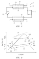
- FIG. 1 is a schematic illustration of a power generation system 10 that includes a working fluid mixture (e.g., an organic, non-azeotropic working fluid mixture) that circulates through a Rankine cycle system 12 (e.g., an organic Rankine cycle system).
- the Rankine cycle system 12 may include a turbine generator 14, a condenser 16 (e.g., a counterflow heat exchanger), a pump 18 and an evaporator 20 (e.g., a counterflow heat exchanger).
- the condenser 16 may include a first heat exchange passage 22 and a second heat exchange passage 24.
- the evaporator 20 may include a first heat exchange passage 26 and a second heat exchange passage 28.
- the working fluid mixture may circulate sequentially through the turbine generator 14, the first heat exchange passage 22 of the condenser, the pump 18 and the second heat exchange passage 28 of the evaporator, which may be connected together in a closed loop circuit.
- the power generation system 10 may also include a liquid receiver/accumulator connected, for example, between the first heat exchange passage 22 and the pump 18.
- a cooling medium e.g. water, seawater, air
- a thermal source fluid may be directed through the first heat exchange passage 26 of the evaporator.
- FIG. 2 is a temperature-entropy phase diagram of the working fluid mixture during operation of the Rankine cycle system 12.
- the phase diagram illustrates a first curve 30 for the organic non-azeotropic working fluid mixture, a second curve 32 for the cooling medium, and a third curve 34 for the thermal source fluid.
- superheated vapor of the working fluid mixture is directed into the turbine generator 14 at point 200.
- the vapor expands and mechanically drives the turbine generator 14 between the point 200 and point 204, which may thereby generate power (e.g., electricity).
- the vapor is directed from the turbine generator 14 into the first heat exchange passage 22 at point 204.
- Thermal energy is transferred from the working fluid mixture into the cooling medium through the condenser 16 between the point 204 and point 206, which may cause the working fluid mixture to undergo a phase change from vapor to liquid.
- the vapor may be, for example, de-superheated within the first heat exchange passage 22 between the point 204 and point 208, and condensed into liquid between the point 208 and point 210.
- the liquid may also be sub-cooled within the first heat exchange passage 22 between the points 210 and 206.
- the liquid is directed from the first heat exchange passage 22 into the pump 18 between the point 206 and point 212.
- the liquid is pressurized within the pump 18 between the point 212 and point 214, and is directed into the second heat transfer passage 28 at point 216.
- Thermal energy is transferred from the thermal source fluid into the working fluid mixture through the evaporator 20 between the point 216 and point 200, which may cause the working fluid mixture to undergo another phase change from the liquid to the vapor.
- the liquid may be, for example, preheated within the second heat exchange passage 28 between the point 216 and point 220, and evaporated into vapor between the points 220 and 218.
- the vapor may also be, for example, superheated beyond point 218 to point 200 to minimize risk of condensation of the mixture vapor in the turbine generator 14. The vapor is then directed from the second heat exchange passage 28 into the turbine generator 14 at point 200.
- the working fluid mixture may exhibit certain properties such as temperature glide during phase change, pressure, bubble point temperature in both the condenser passage 22 and the evaporator passage 28, and a mixture critical pressure that increases (e.g., maximizes) the power generation potential and cycle thermal efficiency during the afore-described Rankine cycle.
- temperature glide describes the temperature difference between the saturated vapor temperature and the saturated liquid temperature of a working fluid mixture.
- saturated vapor temperature describes a dew point temperature of the working fluid mixture; e.g., the temperature at the point 208 during condensation, and the temperature at the point 218 during evaporation.
- saturated liquid temperature describes a bubble point temperature of the working fluid mixture; e.g., the temperature at the point 210 during condensation, and the temperature at the point 220 during evaporation.
- the condenser temperature glide may be, for example, between about five and thirty degrees Kelvin (e.g., between about 6-8°K and 20-25°K).
- the condenser pressure may be, for example, between about one tenth of one percent (0.1 %) and eleven percent of the critical pressure (e.g., between about 1-2.5% and 7.5-8% of the critical pressure) of the working fluid mixture.
- the condenser bubble point temperature at the point 210 may be, for example, between about one and nine degrees Kelvin (e.g., between about 1°K and 5°K) greater than temperature T 5 (e.g., T 5 is between about 280 °K and 308°K) at which the cooling medium is received by the second heat exchange passage 24.
- the critical pressure may be, for example, between about 2 MPa and 6.5 MPa.
- the working fluid mixture may also exhibit other characteristics during the Rankine cycle such as, for example, low global warming potential (GWP), low flammability, low ozone depletion potential, low toxicity, etc.
- GWP global warming potential
- the term "global warming potential” is a relative measure of how much heat a greenhouse gas traps in the atmosphere relative to carbon dioxide for the atmospheric lifetime of the species.
- the global warming potential of carbon dioxide is standardized to 1.
- the global warming potential of the working fluid mixture may be, for example, less than about 675 (e.g., less than about 150-250), and the working fluid mixture may be, for example, non-flammable.
- Some non-azeotropic mixtures may exhibit a lower condensation heat transfer coefficient due to a reduced interfacial temperature between the liquid and vapor phases. This reduced interfacial temperature gives rise to heat and mass transfer resistances.
- the working fluid mixture may be selected such that the condensing heat transfer coefficient of the mixture is greater than the (e.g., smallest) condensing heat transfer coefficient of the components.
- the least volatile component refers to the component with the lowest boiling point at a given temperature.
- the working fluid mixture may be manufactured by mixing together a plurality of different chemical components (e.g., organic chemical components).
- the working fluid mixture may include, for example, a plurality of the chemical components listed in Table 1 below.
- Table 1 Chemical Group Representative Chemical Components (CAS Registry Number) Hydrocarbon Propane (74-98-6), butane (106-97-8), pentane (109-66-0), hexane (110-54-3), heptanes (142-82-5), octane (111-65-9), nonane (111-84-2), decane (124-18-5), ethylene (74-85-1), propylene (115-07-1), propyne (74-99-7), isobutene (75-28-5), isobutene (115-11-7), 1 butene (106-98-9), c2butene (590-18-1), cyclepentane (287-92-3), isopentane (78-78-4), neopentane (463-82-1), iso
- the aforesaid chemical components may be selected, for example, in order to tailor the heat exchanger temperature glide, the heat exchange pressure, the bubble point temperature and/or other characteristics (e.g., the GWP, the flammability, etc.) of the working fluid mixture to a particular Rankine cycle system design and application.
- the chemical components may also be selected, for example, to shift the pinch point in order to reduce a temperature T 6 at which the thermal source fluid exits the heat exchange passage 26 of the evaporator, which may thereby increase Rankine cycle efficiency by increasing the amount of power generated per unit of resource flow.
- the working fluid mixture included in the power generation system 10 in FIG. 1 may include a first chemical component and a second chemical component.
- thermodynamic and transport properties for the refrigerant mixtures provided in Table 2 were generated using the National Institute of Standards and Technology's REFPROP 8.0 database.
- the equations of state for these refrigerant mixtures are generated using empirical estimation schemes (e.g. mixing rules) contained within the database.
- the present invention is not limited to the aforesaid mixing rules.
- the working fluid mixture may also include one or more additional chemical components and/or compounds selected to, for example, enhance system performance, enhance heat transfer between the Rankine cycle fluids, enhance diagnostics, provide fire suppression, provide lubrication, provide fluid stabilization, provide corrosion resistance, etc.
- the working fluid mixture may include, for example, flammability inhibitors, oils, lubricants, heat transfer enhancement agents, tracers, etc.
- the cooling medium may be water, air or a combination thereof.
- the water may be received from an underground reservoir, a lake, a stream or the sea.
- the cooling medium may also be a process stream that may condense the working fluid mixture.
- the cooling medium may be received from a heat sink having a sink temperature between, for example, about 280°K and 308°K.
- the cooling medium may be a working fluid mixture received from another Rankine cycle system, which will be discussed below in further detail.
- the thermal source fluid may be, for example, liquid and/or gas received from a geothermal reservoir, a combustion engine (e.g., a gas turbine engine, an internal combustion engine, etc.), a solar-thermal system, an incinerator or other waste to energy devices, or an industrial system or process.
- the thermal source fluid may be received from a heat source having a source temperature between, for example, about 360°K and 623°K.
- the thermal source fluid may be a working fluid mixture received from another Rankine cycle system, which will be discussed below in further detail.
- the thermal source fluid may be omitted from the power generation system 10 where, for example, the evaporator 20 is configured as a solar-thermal heating system (e.g., a system that heats the working fluid mixture directly via solar energy).
- the turbine generator 14 may be one of a plurality of turbine generators that are, for example, connected in series or parallel together in the Rankine cycle system.
- the evaporator 20 may be one of a plurality of evaporators that are, for example, connected in series or parallel together in the Rankine cycle system.
- the condenser 16 may be one of a plurality of condensers that are, for example, connected in series or parallel together in the Rankine cycle system.
- a power generation system may include an intermediate heat exchanger, a topping cycle (e.g., a first Rankine cycle system that operates at a relatively high temperature), and a bottoming cycle (e.g., a second Rankine cycle system that operates at a relatively low temperature).
- the intermediate heat exchanger may include a condenser passage that receives a first organic working fluid mixture from the topping cycle, and an evaporator passage that receives a second working fluid from the bottoming cycle. The intermediate heat exchanger transfers thermal energy from the first working fluid to the second working fluid.
- the topping cycle e.g., the high temperature ORC system
- the topping cycle may extract heat, either sensible such as from a hot gas or hot liquid, or latent such as from a condensing fluid such as steam in a refrigerant boiler/evaporator, and create a high temperature and a high pressure vapor.
- the bottoming cycle e.g., the low cost/ low temperature ORC system
- FIG. 3 is a schematic illustration of a power generation system 36.
- the power generation system 36 includes an intermediate heat exchanger 38 (e.g., a counterflow heat exchanger), a first working fluid (e.g., an organic, non-azeotropic working fluid mixture) that circulates through a topping cycle 40 (e.g., an organic Rankine cycle system), and a second working fluid (e.g., an organic, non-azeotropic working fluid mixture) that circulates through a bottoming cycle 42 (e.g., an organic Rankine cycle system).
- the intermediate heat exchanger 38 includes a first heat exchange passage 44 and a second heat exchange passage 46.
- the first heat exchange passage 44 forms a condenser passage 48 where the first working fluid is condensed.
- the second heat exchange passage 46 forms an evaporator passage 50 where the second working fluid is evaporated.
- the topping cycle 40 may include a first turbine generator 52, the condenser passage 48, a first pump 56, an evaporator 58 (e.g., a counterflow evaporator), and a liquid receiver/accumulator 54.
- the evaporator 58 may include a first heat exchange passage 60 and a second heat exchange passage 62.
- the bottoming cycle 42 may include a second turbine generator 64 a condenser 68 (e.g., a counterflow condenser), a second liquid receiver/accumulator 66, a second pump 70 and the evaporator passage 50.
- the condenser 68 may include a first heat exchange passage 72 and a second heat exchange passage 74.
- the first working fluid may circulate sequentially through the first turbine generator 52, the first heat exchange passage 44 (i.e., the condenser passage 84 of heat exchanger 38), the first liquid receiver/accumulator 54, the first pump 56 and the second heat exchange passage 62, which may be connected together in a closed loop circuit.
- the second working fluid may circulate sequentially through the second turbine generator 64, the first heat exchange passage 72 (i.e. the condenser 68), the second liquid receiver/accumulator 66, the second pump 70 and the second heat exchange passage 46 (i.e., the evaporator passage 50 of heat exchanger 38), which may be connected together in a closed loop circuit.
- a heat source fluid may be received from a heat source 76, and directed through the first heat exchange passage 60 (i.e., the evaporator 58).
- a cooling medium may be received from a heat sink 78, and directed through the second heat exchange passage 74 (i.e., the condenser 68).
- the working fluids e.g., the non-azeotropic working fluid mixtures
- the working fluids may be selected such that the condensation temperature of the first, higher temperature, cycle is useable for evaporation of the second, lower temperature, cycle.
- the thermal efficiencies of the organic Rankine cycle may be increased through increased utilization of the available thermal energy.
- a relatively high temperature non-azeotropic mixture may be directed through the topping cycle and a relatively low temperature non-azeotropic mixture may be directed through the bottoming cycle.
- the use of the non-azeotropic mixture in the topping cycle may enable increased utilization of the thermal source fluid through glide matching.
- the use of a non-azeotropic mixture in the bottoming cycle may reduce (e.g., minimize) irreversibilities realized in the intermediate heat exchanger where the fluid's evaporating glide is equal to the condensing glide of the topping cycle's working fluid mixture.
- FIG. 4 illustrates a temperature-entropy (T-s) phase diagram of the aforesaid working fluid mixtures during operation of such a power generation system.
- the phase diagram illustrates a first curve 400 for the non-azeotropic mixture directed through the topping cycle, and a second curve 402 for the non-azeotropic mixture directed through the bottoming cycle.
- one or more of the heat exchangers may be configured as a plate-frame counter-flow heat exchanger, a one pass direct expansion shell and tube counter-flow heat exchanger, or a plate-shell counter-flow heat exchanger.
- a non-azeotropic first working fluid mixture may be directed through the topping cycle and a second working fluid that exhibits relatively no temperature glide may be directed through the bottoming cycle.
- the working fluid in the bottoming cycle may include a pure substance or an azeotropic mixture of one or more known substances (i.e., chemical components).
- the non-azeotropic mixture in the topping cycle may enable increased utilization of the thermal source fluid through glide matching.
- an azeotropic fluid or pure substance in the bottoming cycle may increase the irreversibilities in the intermediate heat exchanger, the negative impact associated with glide in the bottoming cycle's condenser are reduced (e.g., minimized).
- T-s temperature-entropy phase diagram of the aforesaid working fluids during operation of such a power generation system.
- the phase diagram illustrates a first curve 500 for the non-azeotropic first working fluid mixture directed through the topping cycle, and a second curve 502 for the second working fluid directed through the bottoming cycle.
- a first working fluid that exhibits relatively no temperature glide may be directed through the topping cycle, and a non-azeotropic second working fluid mixture may be directed through the bottoming cycle.
Landscapes
- Engineering & Computer Science (AREA)
- Chemical & Material Sciences (AREA)
- Combustion & Propulsion (AREA)
- Mechanical Engineering (AREA)
- General Engineering & Computer Science (AREA)
- Engine Equipment That Uses Special Cycles (AREA)
Abstract
Description
- The present invention relates to Rankine cycle systems and, in particular, to a non-azeotropic working fluid mixture that may circulate through an organic Rankine cycle system to generate power.
- An organic Rankine cycle (ORC) system may be used for generating electrical power within, for example, a geothermal power generation system. A typical organic Rankine cycle system may include an organic working fluid that is circulated through a pump, an evaporator, a turbine generator and a condenser. A recuperator may be also used if the technical and economical merits warrant. During operation, the evaporator transfers thermal energy from a relatively warm thermal source fluid into the working fluid in order to form working fluid vapor, which drives the turbine generator as the vapor expands. The condenser transfers thermal (e.g., heat) energy from the expanded working fluid vapor into a relatively cool thermal sink fluid in order to condense the working fluid vapor before it is resupplied to the evaporator through the pump.
- A typical organic working fluid may include a single (pure) chemical component, or an azeotropic mixture of different chemical components. Pinch points associated with single component organic working fluids in heat exchangers, however, typically reduce overall efficiencies of the organic Rankine cycle systems in which they are implemented. The term "pinch point" may describe a point in a working fluid temperature profile where a minimum (smallest) temperature difference exists between the temperature of the working fluid and that of the thermal source or sink fluid.
- According to a first aspect of the invention, a power generation system includes a non-azeotropic working fluid mixture and a Rankine cycle system. The Rankine cycle system includes a turbine generator that is driven by vapor of the working fluid mixture, and a condenser that exchanges thermal energy between the vapor received from the turbine generator and a cooling medium. The working fluid mixture exhibits a condenser temperature glide between approximately five degrees and thirty degrees Kelvin, a condensing pressure between approximately one tenth of one percent and eleven percent of a critical pressure of the working fluid mixture, and a condenser bubble point temperature between approximately one degree and nine degrees Kelvin greater than a temperature at which the cooling medium is received by the condenser.
- According to a second aspect of the invention, a power generation system includes an intermediate heat exchanger, a first Rankine cycle system and a second Rankine cycle system. The heat exchanger includes a condenser passage that receives a first working fluid, and an evaporator passage that receives an organic, non-azeotropic second working fluid mixture. The heat exchanger transfers thermal energy from the first working fluid to the second working fluid mixture. The first Rankine cycle system includes a first pump that directs the first working fluid through an evaporator and the condenser passage. The second Rankine cycle system includes a second pump that directs the second working fluid mixture through the evaporator passage, a turbine generator that is driven by vapor of the second working fluid mixture, and a condenser that exchanges thermal energy between the vapor received from the turbine generator and a cooling medium. The second working fluid mixture is characterized by a condenser temperature glide between approximately five degrees and thirty degrees Kelvin, a condensing pressure between approximately one tenth of one percent and eleven percent of a critical pressure of the second working fluid mixture, and a condenser bubble point temperature between approximately one degree and nine degrees Kelvin greater than a temperature at which the cooling medium is received by the condenser.
- The foregoing features and the operation of the invention will become more apparent in light of the following description and the accompanying drawings.
-
-
FIG. 1 is a schematic illustration of a power generation system that includes a Rankine cycle system; -
FIG. 2 is a temperature-entropy phase diagram for an organic, non-azeotropic working fluid mixture circulating through the Rankine cycle system illustrated inFIG. 1 ; and -
FIG. 3 is a schematic illustration of an alternate embodiment power generation system that includes a plurality of Rankine cycle systems. -
FIG. 4 is a temperature-entropy phase diagram of working fluid mixtures during operation of a power generation system. -
FIG. 5 is another temperature-entropy phase diagram of working fluids during operation of a power generation system. -
FIG. 1 is a schematic illustration of apower generation system 10 that includes a working fluid mixture (e.g., an organic, non-azeotropic working fluid mixture) that circulates through a Rankine cycle system 12 (e.g., an organic Rankine cycle system). The Rankinecycle system 12 may include a turbine generator 14, a condenser 16 (e.g., a counterflow heat exchanger), apump 18 and an evaporator 20 (e.g., a counterflow heat exchanger). Thecondenser 16 may include a firstheat exchange passage 22 and a secondheat exchange passage 24. Theevaporator 20 may include a firstheat exchange passage 26 and a secondheat exchange passage 28. - During operation, the working fluid mixture may circulate sequentially through the turbine generator 14, the first
heat exchange passage 22 of the condenser, thepump 18 and the secondheat exchange passage 28 of the evaporator, which may be connected together in a closed loop circuit. In some embodiments, thepower generation system 10 may also include a liquid receiver/accumulator connected, for example, between the firstheat exchange passage 22 and thepump 18. A cooling medium (e.g. water, seawater, air), may be directed through the secondheat exchange passage 24 of the condenser. A thermal source fluid may be directed through the firstheat exchange passage 26 of the evaporator. -
FIG. 2 is a temperature-entropy phase diagram of the working fluid mixture during operation of the Rankinecycle system 12. The phase diagram illustrates afirst curve 30 for the organic non-azeotropic working fluid mixture, asecond curve 32 for the cooling medium, and athird curve 34 for the thermal source fluid. Referring toFIGS. 1 and 2 , superheated vapor of the working fluid mixture is directed into the turbine generator 14 atpoint 200. The vapor expands and mechanically drives the turbine generator 14 between thepoint 200 andpoint 204, which may thereby generate power (e.g., electricity). The vapor is directed from the turbine generator 14 into the firstheat exchange passage 22 atpoint 204. Thermal energy is transferred from the working fluid mixture into the cooling medium through thecondenser 16 between thepoint 204 andpoint 206, which may cause the working fluid mixture to undergo a phase change from vapor to liquid. The vapor may be, for example, de-superheated within the firstheat exchange passage 22 between thepoint 204 andpoint 208, and condensed into liquid between thepoint 208 andpoint 210. The liquid may also be sub-cooled within the firstheat exchange passage 22 between thepoints heat exchange passage 22 into thepump 18 between thepoint 206 andpoint 212. The liquid is pressurized within thepump 18 between thepoint 212 andpoint 214, and is directed into the secondheat transfer passage 28 atpoint 216. Thermal energy is transferred from the thermal source fluid into the working fluid mixture through theevaporator 20 between thepoint 216 andpoint 200, which may cause the working fluid mixture to undergo another phase change from the liquid to the vapor. The liquid may be, for example, preheated within the secondheat exchange passage 28 between thepoint 216 andpoint 220, and evaporated into vapor between thepoints point 218 topoint 200 to minimize risk of condensation of the mixture vapor in the turbine generator 14. The vapor is then directed from the secondheat exchange passage 28 into the turbine generator 14 atpoint 200. - The working fluid mixture may exhibit certain properties such as temperature glide during phase change, pressure, bubble point temperature in both the
condenser passage 22 and theevaporator passage 28, and a mixture critical pressure that increases (e.g., maximizes) the power generation potential and cycle thermal efficiency during the afore-described Rankine cycle. The term "temperature glide" describes the temperature difference between the saturated vapor temperature and the saturated liquid temperature of a working fluid mixture. The term "saturated vapor temperature" describes a dew point temperature of the working fluid mixture; e.g., the temperature at thepoint 208 during condensation, and the temperature at thepoint 218 during evaporation. The term "saturated liquid temperature" describes a bubble point temperature of the working fluid mixture; e.g., the temperature at thepoint 210 during condensation, and the temperature at thepoint 220 during evaporation. The condenser temperature glide may be, for example, between about five and thirty degrees Kelvin (e.g., between about 6-8°K and 20-25°K). The condenser pressure may be, for example, between about one tenth of one percent (0.1 %) and eleven percent of the critical pressure (e.g., between about 1-2.5% and 7.5-8% of the critical pressure) of the working fluid mixture. The condenser bubble point temperature at thepoint 210 may be, for example, between about one and nine degrees Kelvin (e.g., between about 1°K and 5°K) greater than temperature T5 (e.g., T5 is between about 280 °K and 308°K) at which the cooling medium is received by the secondheat exchange passage 24. The critical pressure may be, for example, between about 2 MPa and 6.5 MPa. - The working fluid mixture may also exhibit other characteristics during the Rankine cycle such as, for example, low global warming potential (GWP), low flammability, low ozone depletion potential, low toxicity, etc. The term "global warming potential" is a relative measure of how much heat a greenhouse gas traps in the atmosphere relative to carbon dioxide for the atmospheric lifetime of the species. The global warming potential of carbon dioxide is standardized to 1. The global warming potential of the working fluid mixture may be, for example, less than about 675 (e.g., less than about 150-250), and the working fluid mixture may be, for example, non-flammable.
- Some non-azeotropic mixtures may exhibit a lower condensation heat transfer coefficient due to a reduced interfacial temperature between the liquid and vapor phases. This reduced interfacial temperature gives rise to heat and mass transfer resistances. In order to avoid such implications, the working fluid mixture may be selected such that the condensing heat transfer coefficient of the mixture is greater than the (e.g., smallest) condensing heat transfer coefficient of the components. The least volatile component refers to the component with the lowest boiling point at a given temperature.
- The working fluid mixture may be manufactured by mixing together a plurality of different chemical components (e.g., organic chemical components). The working fluid mixture may include, for example, a plurality of the chemical components listed in Table 1 below.
TABLE 1 Chemical Group Representative Chemical Components (CAS Registry Number) Hydrocarbon Propane (74-98-6), butane (106-97-8), pentane (109-66-0), hexane (110-54-3), heptanes (142-82-5), octane (111-65-9), nonane (111-84-2), decane (124-18-5), ethylene (74-85-1), propylene (115-07-1), propyne (74-99-7), isobutene (75-28-5), isobutene (115-11-7), 1 butene (106-98-9), c2butene (590-18-1), cyclepentane (287-92-3), isopentane (78-78-4), neopentane (463-82-1), isohexane (107-83-5), cyclohexane (110-82-7) Fluorocarbon R14 (75-73-0), R218 (76-19-7) Ether RE170 (dimethyl ether 115-10-6) Hydrochlorofluorocarbon R21 (75-43-4), R22 (75-45-6), R30 (75-09-2), R32 (75-10-5), R41 (593-53-3), R123 (306-83-2), R124 (2837-89-0) Hydrofluorocarbon R134a (811-97-2), R143a (420-46-2), R152a (75-37-6), R161 (353-36-6), R23 (75-46-7), R227ea (431-89-0), R236ea (431-63-0), R236fa (690-39-1), R245ca (679-86-7), R245fa (460-73-1), R365mfc (406-58-6), R338mccq (662-35-1) Fluorinated Ketone 1,1,1,2,2,4,5,5,5-nonafluoro-4-(trifluoromethyl)-3-pentanone (e.g., Novec®649) (756-13-8), C7FK (C7 fluoroketone) Hydrofluoro ether RE125 (3822-68-2), RE134, RE143a (421-14-7) RE236fa, RE245cb2 (22410-44-2), RE245fa2 (1885-48-9), HFE-7000 (C3F7OCH3), HFE-7100 (C4F9OCH3), HFE-7200 (C4F9OC2H5) Hydrochlorofluoro olefin R1233zd (102687-65-0), 2-chloro-3,3,3-trifluoropropene Bromofluoro olefin C5F9Cl Fluoro olefin R1216 (116-15-4) Hydrofluoro olefin R1234yf (754-12-1), R1234ze (1645-83-6), R1243zf (677-21-4), R1225ye (5595-10-8) Cyclic siloxane D2 (7782-39-0), D4 (556-76-2), D5 (541-02-6), D6 (540-97-6) Linear siloxane MM (107-46-0), MDM (107-51-7), MD2M (141-62-8), MD3M (141-63-9), MD4M (00107-52-8) - The aforesaid chemical components may be selected, for example, in order to tailor the heat exchanger temperature glide, the heat exchange pressure, the bubble point temperature and/or other characteristics (e.g., the GWP, the flammability, etc.) of the working fluid mixture to a particular Rankine cycle system design and application. The chemical components may also be selected, for example, to shift the pinch point in order to reduce a temperature T6 at which the thermal source fluid exits the
heat exchange passage 26 of the evaporator, which may thereby increase Rankine cycle efficiency by increasing the amount of power generated per unit of resource flow. The working fluid mixture included in thepower generation system 10 inFIG. 1 , for example, may include a first chemical component and a second chemical component. Examples of first and second chemical component combinations are listed below in Table 2.TABLE 2 Representative Chemical Components (A + B) Concentration (% by mass) Temp. Glide Range (°K) Crit. Pressure (MPa) Bubble Point Temp. (°K) A B Min. Max. C2butene + hexane 5-90 95-10 10-17 25-31.2 3.1-4.1 289-291 Cyclopentane + Octane 55-95 45-5 9-15.4 27.6-36.2 3.6-4.4 289-291 Isohexane + t2butene 15-95 85-5 10.5 23.8-27.2 3.1-3.9 289-291 Cyclohexane + isopentane 10-95 90-5 7.5 21.5 3.4-4.1 289-291 Pentane + propyne 10-95 90-5 5.9 22.2-31.7 3.5-5.6 289-291 Pentane + R245fa 30-95 70-5 4.8 8.2 3.4-4.1 289-291 Octane + R30 5-25 95-75 13.8 27.6-35.4 4.8-5.8 289-291 Heptane + R30 5-95 95-5 5.6-9.7 13.2-24.6 2.8-5.8 289-291 Isobutane + Pentane 5-90 95-10 5.3 17.7 3.4-3.8 289-291 Cyclohexane + R245ca 10-95 90-5 8.9-9.3 19.1-28.9 4.1-4.7 289-291 Hexane + R245fa 30-95 70-5 8.2 17.8-27 3.1-3.85 289-291 Isohexane + R245fa 30-95 70-5 6.5 18.2-21.9 3.1-3.9 289-291 Cyclopentane + R236ea 45-90 55-10 6.5-9 19.2 4.5-4.65 289-291 Cyclopentane + R152a 10-30 90-70 14.7 21.2-34.4 4.6-4.8 289-291 Heptane + R365mfc 25-80 75-20 13.7 17.7-23.1 2.7-3.1 289-291 Pentane + 1 butene 15-95 85-5 5.2-7.4 14.8 3.5-4.0 289-291 Hexane + R1233zd 5-90 95-10 5.5-7.8 18.4 3.0-3.6 289-291 R245fa + R1234ze 25-70 75-30 5.2 11 3.7-3.9 289-291 Isopentane + R1234ze 5-85 95-15 6.2 16.4-18 3.3-3.6 289-291 Pentane + R1234ze 5-90 95-10 6.6 16.4-23.9 3.3-3.6 289-291 Cyclopentane + R245fa 30-90 70-10 5.1 14.1 4.5-4.75 289-291 Cyclohexane + HFE-7000 5-80 95-20 5.7-8.5 16.1 2.7-4.0 289-291 R152a + R245fa 35-75 65-25 6.7 12.8 4.1-4.5 289-291 R30 + R152a 5-95 95-5 5.6-10.9 22.6-33.8 4.6-6.0 289-291 R236ea + R161 25-55 75-45 5.5-9.9 11.9 4.4-4.9 289-291 R30 + R1234ze 5-90 95-10 8.9 22.5-27.2 3.7-5.85 289-291 Pentane + MM 5-90 95-10 7.2 20.9-31 2.0-3.3 289-291 C7FK + R245fa 30-90 70-10 10.2 19.1-29.8 2.8-3.4 289-291 R30 + MM 5-90 95-10 6.4-9.1 22.3-28 2.1-5.6 289-291 Novec®649 + isobutene 25-95 75-5 8.8 15.4-26.1 2.9-4.0 289-291 Novec®649 + R245fa 45-95 55-5 5.2 12.6 2.0-3.2 289-291 Novec®649 + R236ea 45-65 55-35 10.6 16.1 2.7-3.1 289-291 R245ca + MM 65-90 35-10 11.2 23.3-34.4 3.4-3.9 289-291 R365mfc + MM 10-75 90-25 13.3 23.1-25.1 2.0-3.0 289-291 HFE-7000 + R1234ze 10-95 90-5 6.5 16-23.8 2.6-3.6 289-291 R30 + R245fa 30-45 70-55 5.1 5.8 4.4-4.9 289-291 Isobutane + r365mfc 25-85 75-15 5.8-9.5 17-20.7 3.3-3.6 289-291 R152a + R365mfc 30-90 70-10 6.7-9.8 20.0-32.8 3.9-4.5 289-291 R245fa + CF3l 25-65 75-35 5.6-10.3 16.4-17.8 4.3-4.55 289-291 HFE-7000 + R1243zf 10-40 90-60 6.2-11.7 20.8 3.2-3.5 289-291 R236ea + HFE-7000 15-35 85-65 5 7.4 2.6-2.85 289-291 - The thermodynamic and transport properties for the refrigerant mixtures provided in Table 2 were generated using the National Institute of Standards and Technology's REFPROP 8.0 database. The equations of state for these refrigerant mixtures are generated using empirical estimation schemes (e.g. mixing rules) contained within the database. The present invention, however, is not limited to the aforesaid mixing rules.
- The working fluid mixture may also include one or more additional chemical components and/or compounds selected to, for example, enhance system performance, enhance heat transfer between the Rankine cycle fluids, enhance diagnostics, provide fire suppression, provide lubrication, provide fluid stabilization, provide corrosion resistance, etc. The working fluid mixture may include, for example, flammability inhibitors, oils, lubricants, heat transfer enhancement agents, tracers, etc.
- The cooling medium may be water, air or a combination thereof. The water may be received from an underground reservoir, a lake, a stream or the sea. The cooling medium may also be a process stream that may condense the working fluid mixture. The cooling medium may be received from a heat sink having a sink temperature between, for example, about 280°K and 308°K. In other embodiments, the cooling medium may be a working fluid mixture received from another Rankine cycle system, which will be discussed below in further detail.
- The thermal source fluid may be, for example, liquid and/or gas received from a geothermal reservoir, a combustion engine (e.g., a gas turbine engine, an internal combustion engine, etc.), a solar-thermal system, an incinerator or other waste to energy devices, or an industrial system or process. The thermal source fluid may be received from a heat source having a source temperature between, for example, about 360°K and 623°K. In other embodiments, the thermal source fluid may be a working fluid mixture received from another Rankine cycle system, which will be discussed below in further detail. Alternatively, the thermal source fluid may be omitted from the
power generation system 10 where, for example, theevaporator 20 is configured as a solar-thermal heating system (e.g., a system that heats the working fluid mixture directly via solar energy). - In some embodiments, the turbine generator 14 may be one of a plurality of turbine generators that are, for example, connected in series or parallel together in the Rankine cycle system. In other embodiments, the
evaporator 20 may be one of a plurality of evaporators that are, for example, connected in series or parallel together in the Rankine cycle system. In still other embodiments, thecondenser 16 may be one of a plurality of condensers that are, for example, connected in series or parallel together in the Rankine cycle system. - According to another aspect of the invention, a power generation system may include an intermediate heat exchanger, a topping cycle (e.g., a first Rankine cycle system that operates at a relatively high temperature), and a bottoming cycle (e.g., a second Rankine cycle system that operates at a relatively low temperature). The intermediate heat exchanger may include a condenser passage that receives a first organic working fluid mixture from the topping cycle, and an evaporator passage that receives a second working fluid from the bottoming cycle. The intermediate heat exchanger transfers thermal energy from the first working fluid to the second working fluid. In this cascaded ORC arrangement, the topping cycle (e.g., the high temperature ORC system) may extract heat, either sensible such as from a hot gas or hot liquid, or latent such as from a condensing fluid such as steam in a refrigerant boiler/evaporator, and create a high temperature and a high pressure vapor. The bottoming cycle (e.g., the low cost/ low temperature ORC system) may be used efficiently and cost effectively to convert the lower temperature thermal energy to power.
-
FIG. 3 is a schematic illustration of apower generation system 36. Thepower generation system 36 includes an intermediate heat exchanger 38 (e.g., a counterflow heat exchanger), a first working fluid (e.g., an organic, non-azeotropic working fluid mixture) that circulates through a topping cycle 40 (e.g., an organic Rankine cycle system), and a second working fluid (e.g., an organic, non-azeotropic working fluid mixture) that circulates through a bottoming cycle 42 (e.g., an organic Rankine cycle system). Theintermediate heat exchanger 38 includes a firstheat exchange passage 44 and a secondheat exchange passage 46. The firstheat exchange passage 44 forms acondenser passage 48 where the first working fluid is condensed. The secondheat exchange passage 46 forms anevaporator passage 50 where the second working fluid is evaporated. The toppingcycle 40 may include afirst turbine generator 52, thecondenser passage 48, afirst pump 56, an evaporator 58 (e.g., a counterflow evaporator), and a liquid receiver/accumulator 54. Theevaporator 58 may include a firstheat exchange passage 60 and a secondheat exchange passage 62. The bottomingcycle 42 may include a second turbine generator 64 a condenser 68 (e.g., a counterflow condenser), a second liquid receiver/accumulator 66, asecond pump 70 and theevaporator passage 50. Thecondenser 68 may include a firstheat exchange passage 72 and a secondheat exchange passage 74. - During operation, the first working fluid may circulate sequentially through the
first turbine generator 52, the first heat exchange passage 44 (i.e., the condenser passage 84 of heat exchanger 38), the first liquid receiver/accumulator 54, thefirst pump 56 and the secondheat exchange passage 62, which may be connected together in a closed loop circuit. The second working fluid may circulate sequentially through thesecond turbine generator 64, the first heat exchange passage 72 (i.e. the condenser 68), the second liquid receiver/accumulator 66, thesecond pump 70 and the second heat exchange passage 46 (i.e., theevaporator passage 50 of heat exchanger 38), which may be connected together in a closed loop circuit. A heat source fluid may be received from aheat source 76, and directed through the first heat exchange passage 60 (i.e., the evaporator 58). A cooling medium may be received from aheat sink 78, and directed through the second heat exchange passage 74 (i.e., the condenser 68). - In some embodiments, the working fluids (e.g., the non-azeotropic working fluid mixtures) for the topping and bottoming cycles may be selected such that the condensation temperature of the first, higher temperature, cycle is useable for evaporation of the second, lower temperature, cycle. In this way, the thermal efficiencies of the organic Rankine cycle may be increased through increased utilization of the available thermal energy.
- In some embodiments, a relatively high temperature non-azeotropic mixture may be directed through the topping cycle and a relatively low temperature non-azeotropic mixture may be directed through the bottoming cycle. The use of the non-azeotropic mixture in the topping cycle may enable increased utilization of the thermal source fluid through glide matching. The use of a non-azeotropic mixture in the bottoming cycle may reduce (e.g., minimize) irreversibilities realized in the intermediate heat exchanger where the fluid's evaporating glide is equal to the condensing glide of the topping cycle's working fluid mixture.
FIG. 4 illustrates a temperature-entropy (T-s) phase diagram of the aforesaid working fluid mixtures during operation of such a power generation system. The phase diagram illustrates afirst curve 400 for the non-azeotropic mixture directed through the topping cycle, and asecond curve 402 for the non-azeotropic mixture directed through the bottoming cycle. - The difference of working temperature between the components of the working fluid mixture may become greater as the temperature glide increases. This difference may increase the thermal cycle efficiency of the system. However, high temperature glide working fluid mixtures may require condensers that include a relatively large surface area to provide the desired heat transfer necessary to condense the vapor into liquid. In some embodiments, therefore, one or more of the heat exchangers (e.g., the condenser and the evaporator) may be configured as a plate-frame counter-flow heat exchanger, a one pass direct expansion shell and tube counter-flow heat exchanger, or a plate-shell counter-flow heat exchanger.
- In some embodiments, a non-azeotropic first working fluid mixture may be directed through the topping cycle and a second working fluid that exhibits relatively no temperature glide may be directed through the bottoming cycle. The working fluid in the bottoming cycle may include a pure substance or an azeotropic mixture of one or more known substances (i.e., chemical components). The non-azeotropic mixture in the topping cycle may enable increased utilization of the thermal source fluid through glide matching. Although the use of an azeotropic fluid or pure substance in the bottoming cycle may increase the irreversibilities in the intermediate heat exchanger, the negative impact associated with glide in the bottoming cycle's condenser are reduced (e.g., minimized).
FIG. 5 illustrates a temperature-entropy (T-s) phase diagram of the aforesaid working fluids during operation of such a power generation system. The phase diagram illustrates afirst curve 500 for the non-azeotropic first working fluid mixture directed through the topping cycle, and asecond curve 502 for the second working fluid directed through the bottoming cycle. Alternatively, in other embodiments, a first working fluid that exhibits relatively no temperature glide may be directed through the topping cycle, and a non-azeotropic second working fluid mixture may be directed through the bottoming cycle. - While various embodiments of the present invention have been disclosed, it will be apparent to those of ordinary skill in the art that many more embodiments and implementations are possible within the scope of the invention. The chemical components included in the organic, non-azeotropic working fluid mixture, for example, are not intended to be limited to the chemical groups and components listed in Tables 1 and 2. Accordingly, the present invention is not to be restricted except in light of the attached claims.
Claims (15)
- A power generation system (10), comprising:a non-azeotropic working fluid mixture; anda Rankine cycle system (12) comprising a turbine generator (14) that is driven by vapor of the working fluid mixture, and a condenser (16) that exchanges thermal energy between the vapor received from the turbine generator (14) and a cooling medium, wherein the working fluid mixture exhibits a condenser temperature glide during phase change between approximately five degrees and thirty degrees Kelvin, a condensing pressure between approximately one tenth of one percent and eleven percent of a critical pressure of the working fluid mixture, and a condenser bubble point temperature between approximately one degree and nine degrees Kelvin greater than a temperature at which the cooling medium is received by the condenser (16).
- The system (10) of claim 1, wherein the working fluid mixture comprises a first chemical component and a second chemical component, and the first chemical component and the second chemical component each comprise at least one of a hydrocarbon, a fluorocarbon, an ether, a hydrochlorofluorocarbon, a hydrofluorocarbon, a fluorinated ketone, a hydrofluoro ether, a hydrochlorofluoro olefin, a bromofluoro olefin, a fluoro olefin, a hydrofluoro olefin, a cyclic siloxane and a linear siloxane.
- The system (10) of claim 2, wherein the first chemical component comprises at least one of R134a, R245fa, R236ea, 1,1,1,2,2,4,5,5,5-nonafluoro-4-(trifluoromethyl)-3-pentanone, HFE-7000, R1234ze, R1234yf, R1233zd and R1243zf,
- The system (10) of claim 2 or 3, wherein the second chemical component comprises at least one of pentane, hexane, isohexane, cyclopentane, cyclohexane, R245fa, R1234ze, isopentane, R161, R30, R134a, R1233zd, C7FK, isobutene, 1,1,1,2,2,4,5,5,5-nonafluoro-4-(trifluoromethyl)-3-pentanone, R236ea, HFE-7000, CF3l and R1243zf.
- The system (10) of any preceding claim, wherein the condenser temperature glide is between approximately six degrees and twenty-five degrees Kelvin, and optionally the condenser temperature glide is between approximately eight degrees and twenty degrees Kelvin.
- The system (10) of any preceding claim, wherein the condensing pressure is between approximately one percent and eight percent of the critical pressure of the working fluid mixture, and optionally the condensing pressure is between approximately two and one half percent and seven and one half percent of the critical pressure of the working fluid mixture.
- The system (10) of any preceding claim, wherein the condenser bubble point temperature is between approximately one degree and five degrees Kelvin greater than the temperature at which the cooling medium is received by the condenser (16).
- The system of any preceding claim, wherein the working fluid mixture exhibits a global warming potential less than approximately 675, and optionally the global warming potential is less than approximately 150.
- The system of any preceding claim, wherein the condenser (16) comprises one of a plate-frame counter-flow heat exchanger, a one pass direct expansion shell and tube counter-flow heat exchanger, and a plate-shell counter-flow heat exchanger.
- A power generation system (36), comprising:an intermediate heat exchanger (38) comprising a condenser passage (48) that receives a first working fluid, and an evaporator passage (50) that receives an organic, non-azeotropic second working fluid mixture, wherein the intermediate heat exchanger (38) transfers thermal energy from the first working fluid to the second working fluid mixture;a first Rankine cycle system (40) comprising a first pump (56) that directs the first working fluid through an evaporator (58) and the condenser passage (48); anda second Rankine cycle system (42) comprising a second pump (70) that directs the second working fluid mixture through the evaporator passage (50), a second turbine generator (64) that is driven by vapor of the second working fluid mixture, and a condenser (68) that exchanges thermal energy between the vapor received from the second turbine generator (64) and a cooling medium, wherein the second working fluid mixture is characterized by a condenser temperature glide between approximately five degrees and thirty degrees Kelvin, a condensing pressure between approximately one tenth of one percent and eleven percent of a critical pressure of the second working fluid mixture, and a condenser bubble point temperature between approximately one degree and nine degrees Kelvin greater than a temperature at which the cooling medium is received by the condenser (68).
- The system (36) of claim 10, wherein the second working fluid mixture comprises a first chemical component and a second chemical component, and the first chemical component and the second chemical component each comprise at least one of a hydrocarbon, a fluorocarbon, an ether, a hydrochlorofluorocarbon, a hydrofluorocarbon, a fluorinated ketone, a hydrofluoro ether, a hydrochlorofluoro olefin, a bromofluoro olefin, a fluoro olefin, a hydrofluoro olefin, a cyclic siloxane and a linear siloxane.
- The system (36) of claim 11, wherein the first chemical component comprises at least one of R134a, R245fa, R236ea, 1,1,1,2,2,4,5,5,5-nonafluoro-4-(trifluoromethyl)-3-pentanone, HFE-7000, R1234ze, R1234yf, R1233zd and R1243zf.
- The system (36) of claim 11 or 12, wherein the second chemical component comprises at least one of pentane, hexane, isohexane, cyclopentane, cyclohexane, R245fa, R1234ze, isopentane, R161, R30, R134a, R1233zd, C7FK, isobutene, 1,1,1,2,2,4,5,5,5-nonafluoro-4-(trifluoromethyl)-3-pentanone, R236ea, HFE-7000, CF3l and R1243zf.
- The system (36) of any of claims 10 to 13, wherein the evaporator (58):transfers thermal energy into the first working fluid from a thermal source fluid received from one of a geothermal reservoir, a combustion engine, a solar-thermal system, an incinerator and an industrial system, and the cooling medium comprises at least one of a liquid and a gas; and/orthe evaporator (58) comprises a solar-thermal system.
- The system (36) of any of claims 10 to 14, wherein the first working fluid comprises a first chemical component and a second chemical component, and the first chemical component and the second chemical component each comprise at least one of a hydrocarbon, a fluorocarbon, an ether, a hydrochlorofluorocarbon, a hydrofluorocarbon, a fluorinated ketone, a hydrofluoro ether, a hydrochlorofluoro olefin, a bromofluoro olefin, a fluoro olefin, a hydrofluoro olefin, a cyclic siloxane and a linear siloxane, and optionally wherein:the first chemical component comprises at least one of R134a, R245fa, R236ea, 1,1,1,2,2,4,5,5,5-nonafluoro-4-(trifluoromethyl)-3-pentanone, HFE-7000, R1234ze, R1234yf, R1233zd and R1243zf; and/orthe second chemical component comprises at least one of pentane, hexane, isohexane, cyclopentane, cyclohexane, R245fa, R1234ze, isopentane, R161, R30, R134a, R1233zd, C7FK, isobutene, 1,1,1,2,2,4,5,5,5-nonafluoro-4-(trifluoromethyl)-3-pentanone, R236ea, HFE-7000, CF3l and R1243zf.
Applications Claiming Priority (1)
| Application Number | Priority Date | Filing Date | Title |
|---|---|---|---|
| US13/345,330 US20130174552A1 (en) | 2012-01-06 | 2012-01-06 | Non-azeotropic working fluid mixtures for rankine cycle systems |
Publications (2)
| Publication Number | Publication Date |
|---|---|
| EP2613026A2 true EP2613026A2 (en) | 2013-07-10 |
| EP2613026A3 EP2613026A3 (en) | 2017-04-19 |
Family
ID=47115596
Family Applications (1)
| Application Number | Title | Priority Date | Filing Date |
|---|---|---|---|
| EP12191261.2A Withdrawn EP2613026A3 (en) | 2012-01-06 | 2012-11-05 | Non-azeotropic working fluid mixtures for rankine cycle systems |
Country Status (6)
| Country | Link |
|---|---|
| US (1) | US20130174552A1 (en) |
| EP (1) | EP2613026A3 (en) |
| CN (1) | CN103195524A (en) |
| CA (1) | CA2794061C (en) |
| PH (1) | PH12012000341A1 (en) |
| SG (1) | SG192327A1 (en) |
Cited By (4)
| Publication number | Priority date | Publication date | Assignee | Title |
|---|---|---|---|---|
| WO2013123116A1 (en) | 2012-02-14 | 2013-08-22 | United Technologies Corporation | Composition of zeotropic mixtures having predefined temperature glide |
| FR3027154A1 (en) * | 2014-10-14 | 2016-04-15 | Arkema France | GAS ISOLATION OR EXTINGUISHING ELECTRIC ARCS |
| US10662583B2 (en) * | 2014-07-29 | 2020-05-26 | Siemens Aktiengesellschaft | Industrial plant, paper mill, control device, apparatus and method for drying drying-stock |
| US11133139B2 (en) | 2018-03-22 | 2021-09-28 | Arkema France | Use of 1-chloro-2,3,3,3-tetrafluoropropene for isolating or extinguishing electric arcs |
Families Citing this family (31)
| Publication number | Priority date | Publication date | Assignee | Title |
|---|---|---|---|---|
| WO2011103560A2 (en) * | 2010-02-22 | 2011-08-25 | University Of South Florida | Method and system for generating power from low- and mid- temperature heat sources |
| WO2012122631A1 (en) * | 2011-03-14 | 2012-09-20 | Pyrogenesis Canada Inc. | Method to maximize energy recovery in waste-to-energy processes |
| JP5800295B2 (en) * | 2011-08-19 | 2015-10-28 | 国立大学法人佐賀大学 | Steam power cycle system |
| US9284857B2 (en) * | 2012-06-26 | 2016-03-15 | The Regents Of The University Of California | Organic flash cycles for efficient power production |
| US9453433B2 (en) | 2013-06-21 | 2016-09-27 | Sankar K. Mohan | Systems and methods for reducing parasitic losses in closed loop systems |
| CN103374332A (en) * | 2013-07-04 | 2013-10-30 | 天津大学 | Organic rankine cycle mixing working medium with cyclopentane |
| JP6487163B2 (en) * | 2014-07-31 | 2019-03-20 | 三菱重工サーマルシステムズ株式会社 | Turbo refrigerator |
| US10436075B2 (en) * | 2015-01-05 | 2019-10-08 | General Electric Company | Multi-pressure organic Rankine cycle |
| ES2908787T3 (en) * | 2017-01-13 | 2022-05-03 | Honeywell Int Inc | Coolant, heat transfer compositions, methods and systems |
| US10371422B2 (en) * | 2017-02-13 | 2019-08-06 | Daikin Applied Americas Inc. | Condenser with tube support structure |
| CN108437744A (en) * | 2018-04-18 | 2018-08-24 | 上海理工大学 | Secondary circuit automotive air-conditioning system based on R1234yf refrigerants |
| JP6941076B2 (en) * | 2018-06-05 | 2021-09-29 | 株式会社神戸製鋼所 | Power generation method |
| CA3097538C (en) * | 2018-11-13 | 2021-04-27 | Lochterra Inc. | Systems and methods for the capture of heat energy, long-distance conveyance, storage, and distribution of the captured-heat energy and power generated therefrom |
| CN109812309B (en) * | 2019-01-17 | 2024-06-07 | 江苏大学 | Supercritical double-expansion two-stage backheating organic Rankine cycle system |
| CN110953030A (en) * | 2019-11-19 | 2020-04-03 | 深圳市凯盛科技工程有限公司 | Method and device for generating electricity by using waste heat of glass kiln |
| US11592009B2 (en) | 2021-04-02 | 2023-02-28 | Ice Thermal Harvesting, Llc | Systems and methods for generation of electrical power at a drilling rig |
| US11480074B1 (en) | 2021-04-02 | 2022-10-25 | Ice Thermal Harvesting, Llc | Systems and methods utilizing gas temperature as a power source |
| US11486370B2 (en) | 2021-04-02 | 2022-11-01 | Ice Thermal Harvesting, Llc | Modular mobile heat generation unit for generation of geothermal power in organic Rankine cycle operations |
| US12312981B2 (en) | 2021-04-02 | 2025-05-27 | Ice Thermal Harvesting, Llc | Systems and methods utilizing gas temperature as a power source |
| US11421663B1 (en) | 2021-04-02 | 2022-08-23 | Ice Thermal Harvesting, Llc | Systems and methods for generation of electrical power in an organic Rankine cycle operation |
| US11644015B2 (en) | 2021-04-02 | 2023-05-09 | Ice Thermal Harvesting, Llc | Systems and methods for generation of electrical power at a drilling rig |
| US11293414B1 (en) | 2021-04-02 | 2022-04-05 | Ice Thermal Harvesting, Llc | Systems and methods for generation of electrical power in an organic rankine cycle operation |
| US11493029B2 (en) | 2021-04-02 | 2022-11-08 | Ice Thermal Harvesting, Llc | Systems and methods for generation of electrical power at a drilling rig |
| US11359576B1 (en) | 2021-04-02 | 2022-06-14 | Ice Thermal Harvesting, Llc | Systems and methods utilizing gas temperature as a power source |
| US11255315B1 (en) | 2021-04-02 | 2022-02-22 | Ice Thermal Harvesting, Llc | Controller for controlling generation of geothermal power in an organic Rankine cycle operation during hydrocarbon production |
| KR102620257B1 (en) * | 2021-07-20 | 2024-01-03 | 주식회사 씨지아이 | Vapor chamber and working fluid used therefor |
| CN113563847B (en) * | 2021-07-27 | 2022-04-15 | 珠海格力电器股份有限公司 | Quaternary environment-friendly mixed refrigerant, preparation method thereof and refrigeration system |
| CN114350321B (en) * | 2021-12-03 | 2024-02-09 | 湖北瑞能华辉能源管理有限公司 | An energy-saving and environmentally friendly heat pump working fluid and its application |
| US12534990B2 (en) | 2022-12-29 | 2026-01-27 | Ice Thermal Harvesting, Llc | Power generation assemblies for hydraulic fracturing systems and methods |
| US12180861B1 (en) | 2022-12-30 | 2024-12-31 | Ice Thermal Harvesting, Llc | Systems and methods to utilize heat carriers in conversion of thermal energy |
| CN116669399A (en) * | 2023-07-19 | 2023-08-29 | 中国石油大学(华东) | Novel mode for self-adaptive cooling of microelectronic device hot spot |
Family Cites Families (27)
| Publication number | Priority date | Publication date | Assignee | Title |
|---|---|---|---|---|
| US4242870A (en) * | 1974-08-29 | 1981-01-06 | Searingen Judson S | Power systems using heat from hot liquid |
| JPS5674599A (en) * | 1979-11-26 | 1981-06-20 | Toshiba Corp | Heat energy exchanging system |
| FR2483009A1 (en) * | 1980-05-23 | 1981-11-27 | Inst Francais Du Petrole | PROCESS FOR PRODUCING MECHANICAL ENERGY FROM HEAT USING A MIXTURE OF FLUIDS AS A WORKING AGENT |
| US4827877A (en) * | 1987-01-13 | 1989-05-09 | Hisaka Works, Limited | Heat recovery system utilizing non-azeotropic medium |
| US4779424A (en) * | 1987-01-13 | 1988-10-25 | Hisaka Works, Limited | Heat recovery system utilizing non-azeotropic medium |
| US4785876A (en) * | 1987-01-13 | 1988-11-22 | Hisaka Works, Limited | Heat recovery system utilizing non-azetotropic medium |
| CN1083474C (en) * | 1995-10-24 | 2002-04-24 | 顾雏军 | Improved Zeotropic Working Medium Used in Thermodynamic Cycles |
| WO1998006791A1 (en) * | 1996-08-14 | 1998-02-19 | Alliedsignal Inc. | Pentafluoropropanes and hexafluoropropanes as working fluids for power generation |
| US5842345A (en) * | 1997-09-29 | 1998-12-01 | Air Products And Chemicals, Inc. | Heat recovery and power generation from industrial process streams |
| JP2000105024A (en) * | 1998-09-29 | 2000-04-11 | Hisaka Works Ltd | Plate condenser |
| DE19907512A1 (en) * | 1999-02-22 | 2000-08-31 | Frank Eckert | Apparatus for Organic Rankine Cycle (ORC) process has a fluid regenerator in each stage to achieve a greater temperature differential between the cascade inlet and outlet |
| US20040211184A1 (en) * | 2003-04-04 | 2004-10-28 | Desikan Bharathan | Convection towers for air cooled heat exchangers |
| ES2293384T3 (en) * | 2003-12-22 | 2008-03-16 | Ecoenergy Patent Gmbh | PROCEDURE FOR ENERGY CONVERSION ENDS IN MECHANIZED ENERGY WITH A LOW PRESSURE EXPANSION DEVICE. |
| US7428816B2 (en) * | 2004-07-16 | 2008-09-30 | Honeywell International Inc. | Working fluids for thermal energy conversion of waste heat from fuel cells using Rankine cycle systems |
| CN101248253B (en) * | 2005-03-29 | 2010-12-29 | Utc电力公司 | Cascade Organic Rankine Cycle Using Waste Heat |
| GB0614080D0 (en) * | 2006-07-17 | 2006-08-23 | Ineos Fluor Holdings Ltd | Heat transfer compositions |
| WO2009047542A1 (en) * | 2007-10-12 | 2009-04-16 | Ineos Fluor Holdings Limited | Heat transfer compositions |
| US8333901B2 (en) * | 2007-10-12 | 2012-12-18 | Mexichem Amanco Holding S.A. De C.V. | Heat transfer compositions |
| US8512591B2 (en) * | 2007-10-12 | 2013-08-20 | Mexichem Amanco Holding S.A. De C.V. | Heat transfer compositions |
| CN101216020B (en) * | 2007-12-28 | 2011-11-09 | 天津大学 | Multilevel solar energy middle and low temperature Rankine cycle system |
| CN101235273A (en) * | 2007-12-28 | 2008-08-06 | 天津大学 | Binary mixed working fluid for solar low temperature Rankine cycle system |
| GB0906547D0 (en) * | 2009-04-16 | 2009-05-20 | Ineos Fluor Holdings Ltd | Heat transfer compositions |
| US8381508B2 (en) * | 2009-05-28 | 2013-02-26 | Alliant Techsystems Inc. | Closed-cycle rocket engine assemblies and methods of operating such rocket engine assemblies |
| GB0922288D0 (en) * | 2009-12-21 | 2010-02-03 | Rpl Holdings Ltd | Non ozone depleting and low global warming potential refrigerants for refrigeration |
| GB201002618D0 (en) * | 2010-02-16 | 2010-03-31 | Ineos Fluor Ltd | Heat transfet compositions |
| WO2011103560A2 (en) * | 2010-02-22 | 2011-08-25 | University Of South Florida | Method and system for generating power from low- and mid- temperature heat sources |
| US20120067049A1 (en) * | 2010-09-17 | 2012-03-22 | United Technologies Corporation | Systems and methods for power generation from multiple heat sources using customized working fluids |
-
2012
- 2012-01-06 US US13/345,330 patent/US20130174552A1/en not_active Abandoned
- 2012-11-01 CA CA2794061A patent/CA2794061C/en active Active
- 2012-11-05 SG SG2012081618A patent/SG192327A1/en unknown
- 2012-11-05 EP EP12191261.2A patent/EP2613026A3/en not_active Withdrawn
- 2012-11-06 PH PH12012000341A patent/PH12012000341A1/en unknown
- 2012-11-06 CN CN2012105586621A patent/CN103195524A/en active Pending
Non-Patent Citations (1)
| Title |
|---|
| None |
Cited By (6)
| Publication number | Priority date | Publication date | Assignee | Title |
|---|---|---|---|---|
| WO2013123116A1 (en) | 2012-02-14 | 2013-08-22 | United Technologies Corporation | Composition of zeotropic mixtures having predefined temperature glide |
| EP2814898A4 (en) * | 2012-02-14 | 2016-03-02 | United Technologies Corp | COMPOSITION OF ZEOTROPIC MIXTURES HAVING A PREDEFINED TEMPERATURE SLIP |
| US10662583B2 (en) * | 2014-07-29 | 2020-05-26 | Siemens Aktiengesellschaft | Industrial plant, paper mill, control device, apparatus and method for drying drying-stock |
| FR3027154A1 (en) * | 2014-10-14 | 2016-04-15 | Arkema France | GAS ISOLATION OR EXTINGUISHING ELECTRIC ARCS |
| WO2016059075A1 (en) * | 2014-10-14 | 2016-04-21 | Arkema France | Electrical insulation or electric arc extinguishing gas |
| US11133139B2 (en) | 2018-03-22 | 2021-09-28 | Arkema France | Use of 1-chloro-2,3,3,3-tetrafluoropropene for isolating or extinguishing electric arcs |
Also Published As
| Publication number | Publication date |
|---|---|
| US20130174552A1 (en) | 2013-07-11 |
| CA2794061C (en) | 2015-05-12 |
| CA2794061A1 (en) | 2013-07-06 |
| CN103195524A (en) | 2013-07-10 |
| PH12012000341A1 (en) | 2016-01-18 |
| SG192327A1 (en) | 2013-08-30 |
| EP2613026A3 (en) | 2017-04-19 |
Similar Documents
| Publication | Publication Date | Title |
|---|---|---|
| CA2794061C (en) | Non-azeotropic working fluid mixtures for rankine cycle systems | |
| RU2567480C2 (en) | Method of generation of electric energy and also working medium application | |
| Chen et al. | A supercritical Rankine cycle using zeotropic mixture working fluids for the conversion of low-grade heat into power | |
| CN104185717B (en) | System and method for recovering waste heat from dual heat sources | |
| JP5567961B2 (en) | Double reheat Rankine cycle system and method | |
| CN103038457B (en) | Direct evaporator plant and energy recovery system | |
| JP2018204015A5 (en) | ||
| JP2010540837A (en) | Cascade type organic Rankine cycle (ORC) system using waste heat from reciprocating engine | |
| KR20060134049A (en) | Organic Rankine Cycle Fluid | |
| KR20060054394A (en) | Method and apparatus for performing a thermodynamic cycle | |
| EP3008299B1 (en) | Falling film evaporator for mixed refrigerants | |
| Brasz et al. | Ranking of working fluids for organic Rankine cycle applications | |
| US20120067049A1 (en) | Systems and methods for power generation from multiple heat sources using customized working fluids | |
| WO1998006791A1 (en) | Pentafluoropropanes and hexafluoropropanes as working fluids for power generation | |
| CN101929361B (en) | A low temperature power cycle system with absorber | |
| Li et al. | Working fluid selection based on critical temperature and water temperature in organic Rankine cycle | |
| WO2009045117A2 (en) | A method of utilising low- and medium-temperature heat sources and media and a system for utilising low- and medium-temperature heat sources and media | |
| WO2005085398A2 (en) | Fluorinated ketone and fluorinated ethers as working fluids for thermal energy conversion | |
| Caresana et al. | Micro combined plant with gas turbine and organic cycle | |
| JP6868022B2 (en) | How to generate electricity using a combined cycle | |
| Zhu et al. | A thermodynamics comparison of subcritical and transcritical organic Rankine cycle system for power generation | |
| Ali et al. | A computer program for working fluid selection of low temperature organic rankine cycle | |
| RU2569993C2 (en) | Operation of thermal electric power station | |
| RU2569994C2 (en) | Operation of thermal electric power station | |
| JP2012247102A (en) | Heat pump |
Legal Events
| Date | Code | Title | Description |
|---|---|---|---|
| PUAI | Public reference made under article 153(3) epc to a published international application that has entered the european phase |
Free format text: ORIGINAL CODE: 0009012 |
|
| AK | Designated contracting states |
Kind code of ref document: A2 Designated state(s): AL AT BE BG CH CY CZ DE DK EE ES FI FR GB GR HR HU IE IS IT LI LT LU LV MC MK MT NL NO PL PT RO RS SE SI SK SM TR |
|
| AX | Request for extension of the european patent |
Extension state: BA ME |
|
| RAP1 | Party data changed (applicant data changed or rights of an application transferred) |
Owner name: UNITED TECHNOLOGIES CORPORATION |
|
| RAP1 | Party data changed (applicant data changed or rights of an application transferred) |
Owner name: NANJING TICA AIR-CONDITIONING CO., LTD. |
|
| PUAL | Search report despatched |
Free format text: ORIGINAL CODE: 0009013 |
|
| AK | Designated contracting states |
Kind code of ref document: A3 Designated state(s): AL AT BE BG CH CY CZ DE DK EE ES FI FR GB GR HR HU IE IS IT LI LT LU LV MC MK MT NL NO PL PT RO RS SE SI SK SM TR |
|
| AX | Request for extension of the european patent |
Extension state: BA ME |
|
| RIC1 | Information provided on ipc code assigned before grant |
Ipc: F01K 23/02 20060101AFI20170311BHEP Ipc: F01K 25/08 20060101ALI20170311BHEP |
|
| RAP1 | Party data changed (applicant data changed or rights of an application transferred) |
Owner name: NANJING TICA CLIMATE SOLUTIONS CO., LTD. |
|
| 17P | Request for examination filed |
Effective date: 20171018 |
|
| RBV | Designated contracting states (corrected) |
Designated state(s): AL AT BE BG CH CY CZ DE DK EE ES FI FR GB GR HR HU IE IS IT LI LT LU LV MC MK MT NL NO PL PT RO RS SE SI SK SM TR |
|
| 17Q | First examination report despatched |
Effective date: 20200323 |
|
| STAA | Information on the status of an ep patent application or granted ep patent |
Free format text: STATUS: THE APPLICATION HAS BEEN WITHDRAWN |
|
| 18W | Application withdrawn |
Effective date: 20200721 |