EP2613009A2 - Turbine assembly and method for reducing fluid flow between turbine components - Google Patents
Turbine assembly and method for reducing fluid flow between turbine components Download PDFInfo
- Publication number
- EP2613009A2 EP2613009A2 EP12198421.5A EP12198421A EP2613009A2 EP 2613009 A2 EP2613009 A2 EP 2613009A2 EP 12198421 A EP12198421 A EP 12198421A EP 2613009 A2 EP2613009 A2 EP 2613009A2
- Authority
- EP
- European Patent Office
- Prior art keywords
- slashface
- pin
- bucket
- turbine
- turbine assembly
- Prior art date
- Legal status (The legal status is an assumption and is not a legal conclusion. Google has not performed a legal analysis and makes no representation as to the accuracy of the status listed.)
- Withdrawn
Links
- 239000012530 fluid Substances 0.000 title claims abstract description 31
- 238000000034 method Methods 0.000 title claims description 13
- 238000001816 cooling Methods 0.000 claims description 9
- 239000007789 gas Substances 0.000 description 27
- 239000000446 fuel Substances 0.000 description 12
- 239000000843 powder Substances 0.000 description 6
- 229910000828 alnico Inorganic materials 0.000 description 5
- 239000000203 mixture Substances 0.000 description 5
- 239000007921 spray Substances 0.000 description 5
- 239000000463 material Substances 0.000 description 4
- KPLQYGBQNPPQGA-UHFFFAOYSA-N cobalt samarium Chemical compound [Co].[Sm] KPLQYGBQNPPQGA-UHFFFAOYSA-N 0.000 description 3
- 229910000938 samarium–cobalt magnet Inorganic materials 0.000 description 3
- UFHFLCQGNIYNRP-UHFFFAOYSA-N Hydrogen Chemical compound [H][H] UFHFLCQGNIYNRP-UHFFFAOYSA-N 0.000 description 2
- 229910045601 alloy Inorganic materials 0.000 description 2
- 239000000956 alloy Substances 0.000 description 2
- 239000011248 coating agent Substances 0.000 description 2
- 238000000576 coating method Methods 0.000 description 2
- 239000012809 cooling fluid Substances 0.000 description 2
- 239000001257 hydrogen Substances 0.000 description 2
- 229910052739 hydrogen Inorganic materials 0.000 description 2
- 239000000696 magnetic material Substances 0.000 description 2
- VNWKTOKETHGBQD-UHFFFAOYSA-N methane Chemical compound C VNWKTOKETHGBQD-UHFFFAOYSA-N 0.000 description 2
- 238000007789 sealing Methods 0.000 description 2
- 238000011144 upstream manufacturing Methods 0.000 description 2
- 239000000853 adhesive Substances 0.000 description 1
- 230000001070 adhesive effect Effects 0.000 description 1
- 230000004075 alteration Effects 0.000 description 1
- QVGXLLKOCUKJST-UHFFFAOYSA-N atomic oxygen Chemical compound [O] QVGXLLKOCUKJST-UHFFFAOYSA-N 0.000 description 1
- 238000005253 cladding Methods 0.000 description 1
- NDYCBWZIOSTTHS-UHFFFAOYSA-N cobalt samarium Chemical compound [Co].[Co].[Co].[Co].[Co].[Sm] NDYCBWZIOSTTHS-UHFFFAOYSA-N 0.000 description 1
- 238000010288 cold spraying Methods 0.000 description 1
- 238000002485 combustion reaction Methods 0.000 description 1
- 238000004891 communication Methods 0.000 description 1
- 238000010586 diagram Methods 0.000 description 1
- 238000010438 heat treatment Methods 0.000 description 1
- 239000007788 liquid Substances 0.000 description 1
- 239000000314 lubricant Substances 0.000 description 1
- 229910001004 magnetic alloy Inorganic materials 0.000 description 1
- 239000003345 natural gas Substances 0.000 description 1
- 239000001301 oxygen Substances 0.000 description 1
- 229910052760 oxygen Inorganic materials 0.000 description 1
- 230000008569 process Effects 0.000 description 1
- 230000001681 protective effect Effects 0.000 description 1
- 230000008439 repair process Effects 0.000 description 1
- 230000000717 retained effect Effects 0.000 description 1
- 238000005245 sintering Methods 0.000 description 1
- 239000000126 substance Substances 0.000 description 1
- 238000006467 substitution reaction Methods 0.000 description 1
- 230000007704 transition Effects 0.000 description 1
Images

Classifications
-
- F—MECHANICAL ENGINEERING; LIGHTING; HEATING; WEAPONS; BLASTING
- F01—MACHINES OR ENGINES IN GENERAL; ENGINE PLANTS IN GENERAL; STEAM ENGINES
- F01D—NON-POSITIVE DISPLACEMENT MACHINES OR ENGINES, e.g. STEAM TURBINES
- F01D11/00—Preventing or minimising internal leakage of working-fluid, e.g. between stages
- F01D11/005—Sealing means between non relatively rotating elements
- F01D11/006—Sealing the gap between rotor blades or blades and rotor
-
- F—MECHANICAL ENGINEERING; LIGHTING; HEATING; WEAPONS; BLASTING
- F05—INDEXING SCHEMES RELATING TO ENGINES OR PUMPS IN VARIOUS SUBCLASSES OF CLASSES F01-F04
- F05D—INDEXING SCHEME FOR ASPECTS RELATING TO NON-POSITIVE-DISPLACEMENT MACHINES OR ENGINES, GAS-TURBINES OR JET-PROPULSION PLANTS
- F05D2240/00—Components
- F05D2240/55—Seals
-
- F—MECHANICAL ENGINEERING; LIGHTING; HEATING; WEAPONS; BLASTING
- F05—INDEXING SCHEMES RELATING TO ENGINES OR PUMPS IN VARIOUS SUBCLASSES OF CLASSES F01-F04
- F05D—INDEXING SCHEME FOR ASPECTS RELATING TO NON-POSITIVE-DISPLACEMENT MACHINES OR ENGINES, GAS-TURBINES OR JET-PROPULSION PLANTS
- F05D2260/00—Function
- F05D2260/30—Retaining components in desired mutual position
- F05D2260/32—Retaining components in desired mutual position by means of magnetic or electromagnetic forces
-
- F—MECHANICAL ENGINEERING; LIGHTING; HEATING; WEAPONS; BLASTING
- F05—INDEXING SCHEMES RELATING TO ENGINES OR PUMPS IN VARIOUS SUBCLASSES OF CLASSES F01-F04
- F05D—INDEXING SCHEME FOR ASPECTS RELATING TO NON-POSITIVE-DISPLACEMENT MACHINES OR ENGINES, GAS-TURBINES OR JET-PROPULSION PLANTS
- F05D2300/00—Materials; Properties thereof
- F05D2300/50—Intrinsic material properties or characteristics
- F05D2300/507—Magnetic properties
Definitions
- the subject matter disclosed herein relates to gas turbines. More particularly, the subject matter relates to reducing fluid flow between components or regions of gas turbines.
- a combustor converts chemical energy of a fuel or an air-fuel mixture into thermal energy.
- the thermal energy is conveyed by a fluid, often compressed hot air from a compressor, to a turbine where the thermal energy is converted to mechanical energy.
- leakage of fluid between components into the compressed hot air causes a reduced power output and lower efficiency for the turbine.
- leakage of compressed hot air into regions that are typically cooled by cooling fluid can cause component wear, which can lead to downtime for component repair or replacement. Leaks of fluid may be caused by thermal expansion of certain components and relative movement between components during operation of the gas turbine. Accordingly, reducing fluid leaks between components can improve efficiency and durability of the gas turbine.
- a turbine assembly includes a first bucket with a first slashface and a second bucket including a recess formed in a second slashface of the second bucket, wherein the second slashface is adjacent to the first slashface when the first bucket is positioned adjacent to the second bucket.
- the turbine assembly also includes a pin configured to be placed in the recess, wherein the pin is magnetically urged toward the first slashface to reduce fluid flow between the first and second buckets.
- a method for reducing fluid flow between turbine components includes flowing a hot gas across a first bucket and second bucket, wherein the first and second buckets are adjacent. The method also includes flowing a cooling air flow through a radially inner portion of the first and second buckets and positioning a pin between the first and second buckets, wherein a magnetic property urges the pin toward a first slashface of the first bucket, wherein the pin reduces fluid flow between the first and second buckets.
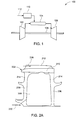
- FIG. 1 is a schematic diagram of an embodiment of a gas turbine system 100.
- the system 100 includes a compressor 102, a combustor 104, a turbine 106, a shaft 108 and a fuel nozzle 110.
- the system 100 may include a plurality of compressors 102, combustors 104, turbines 106, shafts 108 and fuel nozzles 110.
- the compressor 102 and turbine 106 are coupled by the shaft 108.
- the shaft 108 may be a single shaft or a plurality of shaft segments coupled together to form shaft 108.
- the combustor 104 uses liquid and/or gas fuel, such as natural gas or a hydrogen rich synthetic gas, to run the engine.
- fuel nozzles 110 are in fluid communication with an air supply and a fuel supply 112.
- the fuel nozzles 110 create an air-fuel mixture, and discharge the air-fuel mixture into the combustor 104, thereby causing a combustion that heats a pressurized gas.
- the combustor 104 directs the hot pressurized exhaust gas through a transition piece into a turbine nozzle (or "stage one nozzle") and then a turbine bucket, causing turbine 106 rotation.
- the rotation of turbine 106 causes the shaft 108 to rotate, thereby compressing the air as it flows into the compressor 102.
- the turbine components or parts are configured to be assembled with tolerances or gaps to allow for thermal expansion and relative movement of the parts while hot gas flows through the turbine 106.
- turbine efficiency is improved. Specifically, reducing leakage of fluid into the hot gas path or compressed gas flow increases the volume of hot gas flow along the desired path, enabling more work to be extracted from the hot gas. Further, restricting or reducing flow of hot gas into cooling air enables a pressure difference betweent he fluids to be maintained and allows the cooling air to be directed to various parts of the turbine for cooling.
- downstream and upstream are terms that indicate a direction relative to the flow of working fluid through the turbine.
- downstream refers to a direction that generally corresponds to the direction of the flow of working fluid
- upstream generally refers to the direction that is opposite of the direction of flow of working fluid.
- radial refers to movement or position perpendicular to an axis or center line. It may be useful to describe parts that are at differing radial positions with regard to an axis. In this case, if a first component resides closer to the axis than a second component, it may be stated herein that the first component is "radially inward" of the second component.
- first component resides further from the axis than the second component, it may be stated herein that the first component is “radially outward” or “outboard” of the second component.
- axial refers to movement or position parallel to an axis.
- circumferential refers to movement or position around an axis.
- FIG. 2A is a front view of a first bucket 202 while FIG. 2B is a rear view of a second bucket 204 and members, such as pins 206, to be placed between the first bucket 202 and second bucket 204.
- the first bucket 202 includes a shank 208, a platform 210 and an airfoil 212 or blade.
- a slashface 214 of the first bucket 202 is configured to be adjacent to a slashface 216 of the second bucket 204 when the buckets are installed on a wheel or disk with the slashface surfaces facing each other.
- the second bucket 204 includes a shank 218, a platform 220 and an airfoil 222 or blade.
- Recesses 224 and 226 are located in the slashface 216 to receive pins 206, wherein the pins 206 reduce or restrict fluid flow between the first and second buckets 202, 204 when adjoining each other in the turbine.
- the pins 206 are placed in the recesses 224, 226 to reduce flow of a hot gas 228 radially inward into a cooling air 230 and reduce flow of the cooling air 230 radially outward into the hot gas 228.
- the pins 206 reduce axial flow 232 (i.e. along a turbine axis 250) of fluid between the adjacent buckets 202, 204.
- Reducing fluid flow across the shanks 208 and 218 can help maintain a pressure (referred to as “positive pressure” or “pressure difference”) in the cooling air 230 relative to the hot gas 228, thereby enabling distribution of the cooling air 230 throughout the turbine to reduce thermal fatigue and wear. Moreover, preventing cooling fluid 230 from entering the hot gas 228 flow enables more work to be extracted from the hot gas 228 to improve turbine efficiency.
- the pins 206 have a magnetic property, such as a magnetic layer 234, that urges the pins toward the slashfaces 214 to improve the seal or flow restriction.
- the slashface 214 has a magnetic property, such as a magnetic layer 236, that urges the pins toward the slashface 214 to improve the seal or flow restriction.
- a magnetic property in the slashface 216, such as magnetic layer 238, may also urge the pins 206 toward slashface 214.
- the magnetic property in slashface 216 and recesses 224, 226 repel the pins from the slashface surface.
- the magnetic properties and corresponding layers may be on a portion or substantially the entire surface of the pins 206, slashface 214 and slashface 216.
- the pins 206 are urged toward the slashface 214 via at least one of the magnetic properties of the pins 206, slashface 214 and slashface 216.
- the slashfaces 214 and 216, pins 206 and/or their magnetic layers include magnetic material that provides the desired magnetic properties, including, but not limited to, Alnico and Samarium Cobalt (SmCo 5 ).
- Alnico or Samarium Cobalt may be applied as a layer or added to the part materials as powders, wherein the powders are capable of retaining magnetic properties at about 1000 degrees Fahrenheit.
- the magnetic properties of the buckets 202, 204 and/or pins 206 are retained at about 1200 degrees Fahrenheit.
- the magnetic field strength of the magnetized Alnico buckets 202, 204 and/or pins 206 is a BHmax (the magnetic field strength at the point of maximum energy product of a magnetic material) of about 5 Mega Gauss Oersteds (MGOe).
- the magnetic field strength of the magnetized SmCo 5 buckets 202, 204 and/or pins 206 has a BHmax of about 32 MGOe.
- the magnetic properties of the buckets 202, 204 and/or pins 206 may be provided by any suitable method.
- the magnetic property is a characteristic of the material used to form the buckets or pins.
- the magnetic property is applied to the member as a layer (e.g., layers 234, 236, 238) or coating, wherein the layer is applied to at least part of the surface of the member.
- the magnetic layer may be an alloy (e.g., Alnico) powder, applied by sintering, cladding, adhesives and/or a spray, such as a cold spray.
- the alloy powder is blended with a wax lubricant before the blend or mixture is compacted to the desired shape of the strip.
- One or more strips are compacted to a thickness of 30 mils and sintered at a protective hydrogen atmosphere.
- the sintered strips may be tested to ensure the desired magnetic properties are provided.
- the strip may also be treated to achieve the desired strength properties. Further, the strips may be machined down to achieve a desired thickness to account for part expansion during heat treatment.
- the magnetic layer is clad to the bucket shank or pin using a laser.
- a spray technique such as cold spraying, may be used to apply the layer or coating of magnetic alloy powder to the slashface and/or pins.
- Alnico and/or SmCo 5 powders are sprayed directly on to the shank of the buckets or pins and are then heat treated.
- the application process may use a High Velocity Oxygen Fuel (HVOF) spray or cold spray depending on the application.
- HVOF High Velocity Oxygen Fuel
- FIG. 3 is a detailed side section view of an embodiment of a turbine assembly 300.
- the turbine assembly 300 includes a first bucket 302 and second bucket 304.
- a member, such as a pin 310, is positioned in a recess 312 of the first bucket to reduce fluid flow between the buckets.
- the assembled parts include the first bucket 302 with a slashface 306 adjacent to a slashface 308 of the second bucket 304.
- the slashfaces 306 and 308 may be oriented at a variety of angles with respect to a radius 314 of the turbine and, therefore, the pin 310 may be subjected to a variety of forces that may affect the pin's sealing properties.
- a force such as a normal force, occurs at a contact point 322, wherein the force acts to move the pin 310 away from the slashface 308, thereby leading to an increased fluid flow between the buckets.
- a centrifugal force caused by rotation of the buckets 302, 304 may also urge the pin 310 away from the slashface 308.
- the slashface 308 has a magnetic property such as a magnetic layer 318 that urges the pin 310 in a tangential direction 316 toward the slashface 308.
- the recess 312 has a magnetic property, such as a magnetic layer 320 to repel or urge the pin 310 toward the slashface 308.
- the pin 310 may also have a magnetic property, such as magnetic layer 324, which urges the pin 310 in the direction 316 toward the slashface 308.
- magnetic properties of the recess 312 (in slashface 306), slashface 308, pin 310 or any combination thereof provide urging of the pin 310 toward slashface 308.
- the magnetic properties may include any suitable material or treatment of material, including layers and/or strips, applied by any suitable method to one or more parts of the turbine bucket assembly.
Landscapes
- Engineering & Computer Science (AREA)
- Mechanical Engineering (AREA)
- General Engineering & Computer Science (AREA)
- Turbine Rotor Nozzle Sealing (AREA)
- Coating By Spraying Or Casting (AREA)
Abstract
According to one aspect of the invention, a turbine assembly includes a first bucket with a first slashface and a second bucket (204) including a recess (224) formed in a second slashface (216) of the second bucket, wherein the second slashface is adjacent to the first slashface when the first bucket is positioned adjacent to the second bucket. The turbine assembly also includes a pin (206) configured to be placed in the recess, wherein the pin is magnetically urged toward the first slashface to reduce fluid flow between the first and second buckets.
Description
- The subject matter disclosed herein relates to gas turbines. More particularly, the subject matter relates to reducing fluid flow between components or regions of gas turbines.
- In a gas turbine, a combustor converts chemical energy of a fuel or an air-fuel mixture into thermal energy. The thermal energy is conveyed by a fluid, often compressed hot air from a compressor, to a turbine where the thermal energy is converted to mechanical energy. In some turbine embodiments, leakage of fluid between components into the compressed hot air causes a reduced power output and lower efficiency for the turbine. Further, leakage of compressed hot air into regions that are typically cooled by cooling fluid can cause component wear, which can lead to downtime for component repair or replacement. Leaks of fluid may be caused by thermal expansion of certain components and relative movement between components during operation of the gas turbine. Accordingly, reducing fluid leaks between components can improve efficiency and durability of the gas turbine.
- According to one aspect of the invention, a turbine assembly includes a first bucket with a first slashface and a second bucket including a recess formed in a second slashface of the second bucket, wherein the second slashface is adjacent to the first slashface when the first bucket is positioned adjacent to the second bucket. The turbine assembly also includes a pin configured to be placed in the recess, wherein the pin is magnetically urged toward the first slashface to reduce fluid flow between the first and second buckets.
- According to another aspect of the invention, a method for reducing fluid flow between turbine components includes flowing a hot gas across a first bucket and second bucket, wherein the first and second buckets are adjacent. The method also includes flowing a cooling air flow through a radially inner portion of the first and second buckets and positioning a pin between the first and second buckets, wherein a magnetic property urges the pin toward a first slashface of the first bucket, wherein the pin reduces fluid flow between the first and second buckets.
- These and other advantages and features will become more apparent from the following description taken in conjunction with the drawings.
- The subject matter, which is regarded as the invention, is particularly pointed out and distinctly claimed in the claims at the conclusion of the specification. The foregoing and other features, and advantages of the invention are apparent from the following detailed description taken in conjunction with the accompanying drawings in which:
-
FIG. 1 is a schematic drawing of an embodiment of a gas turbine engine, including a combustor, fuel nozzle, compressor and turbine; -
FIGS. 2A and2B are front and rear views, respectively, of a portion of an exemplary turbine assembly; and -
FIG. 3 is detailed end side view of an exemplary turbine assembly. - The detailed description explains embodiments of the invention, together with advantages and features, by way of example with reference to the drawings.
-
FIG. 1 is a schematic diagram of an embodiment of agas turbine system 100. Thesystem 100 includes acompressor 102, acombustor 104, aturbine 106, ashaft 108 and afuel nozzle 110. In an embodiment, thesystem 100 may include a plurality ofcompressors 102,combustors 104,turbines 106,shafts 108 andfuel nozzles 110. Thecompressor 102 andturbine 106 are coupled by theshaft 108. Theshaft 108 may be a single shaft or a plurality of shaft segments coupled together to formshaft 108. - In an aspect, the
combustor 104 uses liquid and/or gas fuel, such as natural gas or a hydrogen rich synthetic gas, to run the engine. For example,fuel nozzles 110 are in fluid communication with an air supply and afuel supply 112. Thefuel nozzles 110 create an air-fuel mixture, and discharge the air-fuel mixture into thecombustor 104, thereby causing a combustion that heats a pressurized gas. Thecombustor 104 directs the hot pressurized exhaust gas through a transition piece into a turbine nozzle (or "stage one nozzle") and then a turbine bucket, causingturbine 106 rotation. The rotation ofturbine 106 causes theshaft 108 to rotate, thereby compressing the air as it flows into thecompressor 102. The turbine components or parts are configured to be assembled with tolerances or gaps to allow for thermal expansion and relative movement of the parts while hot gas flows through theturbine 106. By reducing flow of a fluid that is cooler than the hot gas into the hot gas path, turbine efficiency is improved. Specifically, reducing leakage of fluid into the hot gas path or compressed gas flow increases the volume of hot gas flow along the desired path, enabling more work to be extracted from the hot gas. Further, restricting or reducing flow of hot gas into cooling air enables a pressure difference betweent he fluids to be maintained and allows the cooling air to be directed to various parts of the turbine for cooling. Methods, systems and arrangements to reduce fluid leakage between turbine parts, such as stators and rotors, are discussed in detail below with reference toFIGS. 2A ,2B and 3 . The depicted arrangements provide improved sealing or restriction of fluid flow between turbine components. - As used herein, "downstream" and "upstream" are terms that indicate a direction relative to the flow of working fluid through the turbine. As such, the term "downstream" refers to a direction that generally corresponds to the direction of the flow of working fluid, and the term "upstream" generally refers to the direction that is opposite of the direction of flow of working fluid. The term "radial" refers to movement or position perpendicular to an axis or center line. It may be useful to describe parts that are at differing radial positions with regard to an axis. In this case, if a first component resides closer to the axis than a second component, it may be stated herein that the first component is "radially inward" of the second component. If, on the other hand, the first component resides further from the axis than the second component, it may be stated herein that the first component is "radially outward" or "outboard" of the second component. The term "axial" refers to movement or position parallel to an axis. Finally, the term "circumferential" refers to movement or position around an axis. Although the following discussion primarily focuses on gas turbines, the concepts discussed are not limited to gas turbines.
- A portion of an exemplary turbine assembly is shown in
FIGS 2A and2B .FIG. 2A is a front view of afirst bucket 202 whileFIG. 2B is a rear view of asecond bucket 204 and members, such aspins 206, to be placed between thefirst bucket 202 andsecond bucket 204. Thefirst bucket 202 includes ashank 208, aplatform 210 and anairfoil 212 or blade. Aslashface 214 of thefirst bucket 202 is configured to be adjacent to aslashface 216 of thesecond bucket 204 when the buckets are installed on a wheel or disk with the slashface surfaces facing each other. Thesecond bucket 204 includes ashank 218, aplatform 220 and anairfoil 222 or blade.Recesses 224 and 226 (also referred to as "pockets" or "seal slots") are located in theslashface 216 to receivepins 206, wherein thepins 206 reduce or restrict fluid flow between the first andsecond buckets pins 206 are placed in therecesses hot gas 228 radially inward into acooling air 230 and reduce flow of thecooling air 230 radially outward into thehot gas 228. Further, thepins 206 reduce axial flow 232 (i.e. along a turbine axis 250) of fluid between theadjacent buckets shanks cooling air 230 relative to thehot gas 228, thereby enabling distribution of thecooling air 230 throughout the turbine to reduce thermal fatigue and wear. Moreover, preventing coolingfluid 230 from entering thehot gas 228 flow enables more work to be extracted from thehot gas 228 to improve turbine efficiency. - In an embodiment, the
pins 206 have a magnetic property, such as amagnetic layer 234, that urges the pins toward theslashfaces 214 to improve the seal or flow restriction. In embodiments, theslashface 214 has a magnetic property, such as amagnetic layer 236, that urges the pins toward theslashface 214 to improve the seal or flow restriction. A magnetic property in theslashface 216, such asmagnetic layer 238, may also urge thepins 206 towardslashface 214. In an example, the magnetic property inslashface 216 and recesses 224, 226 repel the pins from the slashface surface. The magnetic properties and corresponding layers may be on a portion or substantially the entire surface of thepins 206,slashface 214 andslashface 216. Thepins 206 are urged toward theslashface 214 via at least one of the magnetic properties of thepins 206,slashface 214 andslashface 216. - In an embodiment, the
slashfaces buckets Alnico buckets - The magnetic properties of the
buckets - In another example, a spray technique, such as cold spraying, may be used to apply the layer or coating of magnetic alloy powder to the slashface and/or pins. In an embodiment, Alnico and/or SmCo5 powders are sprayed directly on to the shank of the buckets or pins and are then heat treated. The application process may use a High Velocity Oxygen Fuel (HVOF) spray or cold spray depending on the application. After application of the magnetic layer to the selected part or parts, the magnetic properties may be tested and/or enhanced by other suitable techniques.
-
FIG. 3 is a detailed side section view of an embodiment of aturbine assembly 300. Theturbine assembly 300 includes afirst bucket 302 andsecond bucket 304. A member, such as apin 310, is positioned in arecess 312 of the first bucket to reduce fluid flow between the buckets. As depicted, the assembled parts include thefirst bucket 302 with aslashface 306 adjacent to aslashface 308 of thesecond bucket 304. Theslashfaces radius 314 of the turbine and, therefore, thepin 310 may be subjected to a variety of forces that may affect the pin's sealing properties. In an embodiment, a force, such as a normal force, occurs at acontact point 322, wherein the force acts to move thepin 310 away from theslashface 308, thereby leading to an increased fluid flow between the buckets. Further, a centrifugal force caused by rotation of thebuckets pin 310 away from theslashface 308. Accordingly, in an embodiment, theslashface 308 has a magnetic property such as amagnetic layer 318 that urges thepin 310 in atangential direction 316 toward theslashface 308. When thepin 310 is urged towardslashface 308, the contact between the pin and slashface provides a seal or fluid restriction to prevent flow of fluid between the first andsecond buckets recess 312 has a magnetic property, such as amagnetic layer 320 to repel or urge thepin 310 toward theslashface 308. Further, thepin 310 may also have a magnetic property, such asmagnetic layer 324, which urges thepin 310 in thedirection 316 toward theslashface 308. In embodiments, magnetic properties of the recess 312 (in slashface 306),slashface 308, pin 310 or any combination thereof provide urging of thepin 310 towardslashface 308. The magnetic properties may include any suitable material or treatment of material, including layers and/or strips, applied by any suitable method to one or more parts of the turbine bucket assembly. - While the invention has been described in detail in connection with only a limited number of embodiments, it should be readily understood that the invention is not limited to such disclosed embodiments. Rather, the invention can be modified to incorporate any number of variations, alterations, substitutions or equivalent arrangements not heretofore described, but which are commensurate with the spirit and scope of the invention. Additionally, while various embodiments of the invention have been described, it is to be understood that aspects of the invention may include only some of the described embodiments. Accordingly, the invention is not to be seen as limited by the foregoing description, but is only limited by the scope of the appended claims.
Claims (15)
- A turbine assembly comprising:a first bucket (202) with a first slashface (214),a second bucket (204) including a recess (224,226) formed in a second slashface (216) of the second bucket, wherein the second slashface is adjacent to the first slashface when the first bucket is positioned adjacent to the second bucket; anda pin (206) configured to be placed in the recess, wherein the pin is magnetically urged toward the first slashface to reduce fluid flow between the first and second buckets.
- The turbine assembly of claim 1, wherein the recess is in a shank of the second bucket.
- The turbine assembly of claim 1 or claim 2, wherein the pin is magnetically urged by a magnetic layer on the pin.
- The turbine assembly of any preceding claim, wherein first slashface has a magnetic property to urge the pin toward the first slashface.
- The turbine assembly of claim 5, wherein the magnetic property of the first slashface is caused by a magnetic layer in the first slashface.
- The turbine assembly of any preceding claim, wherein the pin is oriented in a substantially radial direction and urged in a substantially tangential direction.
- The turbine assembly of any preceding claim, comprising two pins placed in two recesses in the second slashface to reduce fluid flow between the first and second buckets.
- A method for reducing fluid flow between turbine components comprising:flowing a hot gas across a first bucket and second bucket, wherein the first and second buckets are adjacent;flowing a cooling air flow through a radially inner portion of the first and second buckets; andpositioning a pin between the first and second buckets, wherein a magnetic property urges the pin toward a first slashface of the first bucket, wherein the pin reduces fluid flow between the first and second buckets.
- The method of claim 8, wherein positioning the pin comprises positioning the pin in a recess formed in a second slashface.
- The method of claim 8 or claim 9, wherein the magnetic property is caused by a magnetic layer on the pin.
- The method of any one of claims 8 to 10, wherein positioning the pin comprises having a magnetic property of the first slashface urge the pin toward the first slashface.
- A turbine assembly comprising:a first component with a first surface,a second component with a second surface configured to be adjacent to the first surface when the first and second components are adjacent; anda member configured to be placed between the first and second components, wherein the member is magnetically urged toward the first surface to reduce fluid flow between the first and second components.
- The turbine assembly of claim 12, comprising a recess formed in the second surface to receive the member.
- The turbine assembly of claim 12 or claim 13, wherein the member is magnetically urged by a magnetic layer on the member.
- The turbine assembly of any one of claims 12 to 14, wherein first surface has a magnetic property to urge the member toward the first surface.
Applications Claiming Priority (1)
| Application Number | Priority Date | Filing Date | Title |
|---|---|---|---|
| US13/343,301 US20130170944A1 (en) | 2012-01-04 | 2012-01-04 | Turbine assembly and method for reducing fluid flow between turbine components |
Publications (1)
| Publication Number | Publication Date |
|---|---|
| EP2613009A2 true EP2613009A2 (en) | 2013-07-10 |
Family
ID=47665822
Family Applications (1)
| Application Number | Title | Priority Date | Filing Date |
|---|---|---|---|
| EP12198421.5A Withdrawn EP2613009A2 (en) | 2012-01-04 | 2012-12-20 | Turbine assembly and method for reducing fluid flow between turbine components |
Country Status (5)
| Country | Link |
|---|---|
| US (1) | US20130170944A1 (en) |
| EP (1) | EP2613009A2 (en) |
| JP (1) | JP2013139792A (en) |
| CN (1) | CN103195488A (en) |
| RU (1) | RU2012158304A (en) |
Cited By (1)
| Publication number | Priority date | Publication date | Assignee | Title |
|---|---|---|---|---|
| US10851661B2 (en) | 2017-08-01 | 2020-12-01 | General Electric Company | Sealing system for a rotary machine and method of assembling same |
Families Citing this family (3)
| Publication number | Priority date | Publication date | Assignee | Title |
|---|---|---|---|---|
| JP6256836B2 (en) * | 2014-01-24 | 2018-01-10 | 三菱重工業株式会社 | Rotating machine blade and rotating machine |
| JP6270531B2 (en) * | 2014-02-21 | 2018-01-31 | 三菱日立パワーシステムズ株式会社 | Rotor body and rotating machine |
| JP6185031B2 (en) * | 2015-09-28 | 2017-08-23 | 京セラ株式会社 | Portable device, control method and control program |
Family Cites Families (8)
| Publication number | Priority date | Publication date | Assignee | Title |
|---|---|---|---|---|
| US2912223A (en) * | 1955-03-17 | 1959-11-10 | Gen Electric | Turbine bucket vibration dampener and sealing assembly |
| US5675874A (en) * | 1996-02-16 | 1997-10-14 | Chen; Chi-Yueh | Magnetic fastener |
| US7575416B2 (en) * | 2006-05-18 | 2009-08-18 | United Technologies Corporation | Rotor assembly for a rotary machine |
| CN101174494B (en) * | 2006-10-31 | 2010-05-12 | 富士康(昆山)电脑接插件有限公司 | Cable and its manufacturing method |
| US7819666B2 (en) * | 2008-11-26 | 2010-10-26 | Schlumberger Technology Corporation | Rotating electrical connections and methods of using the same |
| US8657574B2 (en) * | 2010-11-04 | 2014-02-25 | General Electric Company | System and method for cooling a turbine bucket |
| US8790086B2 (en) * | 2010-11-11 | 2014-07-29 | General Electric Company | Turbine blade assembly for retaining sealing and dampening elements |
| US8684695B2 (en) * | 2011-01-04 | 2014-04-01 | General Electric Company | Damper coverplate and sealing arrangement for turbine bucket shank |
-
2012
- 2012-01-04 US US13/343,301 patent/US20130170944A1/en not_active Abandoned
- 2012-12-20 EP EP12198421.5A patent/EP2613009A2/en not_active Withdrawn
- 2012-12-25 JP JP2012280448A patent/JP2013139792A/en active Pending
- 2012-12-27 RU RU2012158304/06A patent/RU2012158304A/en not_active Application Discontinuation
-
2013
- 2013-01-04 CN CN2013100016240A patent/CN103195488A/en active Pending
Non-Patent Citations (1)
| Title |
|---|
| None |
Cited By (1)
| Publication number | Priority date | Publication date | Assignee | Title |
|---|---|---|---|---|
| US10851661B2 (en) | 2017-08-01 | 2020-12-01 | General Electric Company | Sealing system for a rotary machine and method of assembling same |
Also Published As
| Publication number | Publication date |
|---|---|
| US20130170944A1 (en) | 2013-07-04 |
| RU2012158304A (en) | 2014-07-10 |
| CN103195488A (en) | 2013-07-10 |
| JP2013139792A (en) | 2013-07-18 |
Similar Documents
| Publication | Publication Date | Title |
|---|---|---|
| US8678754B2 (en) | Assembly for preventing fluid flow | |
| EP3121382B1 (en) | Gas turbine engines including channel-cooled hooks for retaining a part relative to an engine casing structure | |
| EP2628904A2 (en) | Turbine assembly and method for reducing fluid flow between turbine components | |
| US10233775B2 (en) | Engine component for a gas turbine engine | |
| US10781709B2 (en) | Turbine engine with a seal | |
| EP3118418B1 (en) | Seal runner with controlled oil lubrication | |
| CN112523820B (en) | Turbine engine assembly | |
| US20160341051A1 (en) | Gas turbine engine component with an abrasive coating | |
| US20180142567A1 (en) | Sealing system for an axial turbomachine and axial turbomachine | |
| US10267171B2 (en) | Seal assembly for a turbomachine | |
| EP2613009A2 (en) | Turbine assembly and method for reducing fluid flow between turbine components | |
| JP2017082772A (en) | Rotor blades and parts by additive manufacturing | |
| US20150198048A1 (en) | Method for producing a stator blade and stator blade | |
| US8210821B2 (en) | Labyrinth seal for turbine dovetail | |
| US9464536B2 (en) | Sealing arrangement for a turbine system and method of sealing between two turbine components | |
| US20150132107A1 (en) | Rotor cooling | |
| US10138746B2 (en) | Gas turbine engine flow control device | |
| US20160281521A1 (en) | Flowing mateface seal | |
| US20130094969A1 (en) | System for sealing a shaft | |
| EP2613006A1 (en) | Turbine assembly and method for reducing fluid flow between turbine components | |
| US10702964B2 (en) | Blade outer air seal surface | |
| US20160123169A1 (en) | Methods and system for fluidic sealing in gas turbine engines | |
| US9771817B2 (en) | Methods and system for fluidic sealing in gas turbine engines | |
| EP2672122B1 (en) | Method for controlling temperature of a turbine engine compressor and compressor of a turbine engine | |
| US10451082B2 (en) | Anti-rotation feature for wear liners |
Legal Events
| Date | Code | Title | Description |
|---|---|---|---|
| PUAI | Public reference made under article 153(3) epc to a published international application that has entered the european phase |
Free format text: ORIGINAL CODE: 0009012 |
|
| AK | Designated contracting states |
Kind code of ref document: A2 Designated state(s): AL AT BE BG CH CY CZ DE DK EE ES FI FR GB GR HR HU IE IS IT LI LT LU LV MC MK MT NL NO PL PT RO RS SE SI SK SM TR |
|
| AX | Request for extension of the european patent |
Extension state: BA ME |
|
| STAA | Information on the status of an ep patent application or granted ep patent |
Free format text: STATUS: THE APPLICATION IS DEEMED TO BE WITHDRAWN |
|
| 18D | Application deemed to be withdrawn |
Effective date: 20150701 |