EP2612815A2 - Speed card-controlled override fuel pump assist field - Google Patents
Speed card-controlled override fuel pump assist field Download PDFInfo
- Publication number
- EP2612815A2 EP2612815A2 EP13151085.1A EP13151085A EP2612815A2 EP 2612815 A2 EP2612815 A2 EP 2612815A2 EP 13151085 A EP13151085 A EP 13151085A EP 2612815 A2 EP2612815 A2 EP 2612815A2
- Authority
- EP
- European Patent Office
- Prior art keywords
- fuel
- jettison
- fuel pump
- aircraft
- rotor
- Prior art date
- Legal status (The legal status is an assumption and is not a legal conclusion. Google has not performed a legal analysis and makes no representation as to the accuracy of the status listed.)
- Granted
Links
- 239000000446 fuel Substances 0.000 title claims abstract description 319
- 239000002828 fuel tank Substances 0.000 claims abstract description 34
- 238000000034 method Methods 0.000 claims abstract description 30
- 238000012544 monitoring process Methods 0.000 claims abstract description 10
- 239000012530 fluid Substances 0.000 claims abstract description 8
- 230000001502 supplementing effect Effects 0.000 claims abstract description 7
- 238000012546 transfer Methods 0.000 claims description 17
- 230000003247 decreasing effect Effects 0.000 claims description 12
- 230000009849 deactivation Effects 0.000 claims description 9
- 230000003111 delayed effect Effects 0.000 claims description 6
- 238000010586 diagram Methods 0.000 description 7
- 238000013461 design Methods 0.000 description 6
- 238000012986 modification Methods 0.000 description 6
- 230000004048 modification Effects 0.000 description 6
- 238000009826 distribution Methods 0.000 description 3
- 238000004891 communication Methods 0.000 description 2
- 238000009434 installation Methods 0.000 description 2
- 238000005304 joining Methods 0.000 description 2
- 238000004519 manufacturing process Methods 0.000 description 2
- 230000002411 adverse Effects 0.000 description 1
- 238000013459 approach Methods 0.000 description 1
- 230000001934 delay Effects 0.000 description 1
- 230000000694 effects Effects 0.000 description 1
- 238000012423 maintenance Methods 0.000 description 1
- 238000005086 pumping Methods 0.000 description 1
Images


Classifications
-
- F—MECHANICAL ENGINEERING; LIGHTING; HEATING; WEAPONS; BLASTING
- F02—COMBUSTION ENGINES; HOT-GAS OR COMBUSTION-PRODUCT ENGINE PLANTS
- F02C—GAS-TURBINE PLANTS; AIR INTAKES FOR JET-PROPULSION PLANTS; CONTROLLING FUEL SUPPLY IN AIR-BREATHING JET-PROPULSION PLANTS
- F02C9/00—Controlling gas-turbine plants; Controlling fuel supply in air- breathing jet-propulsion plants
- F02C9/26—Control of fuel supply
- F02C9/30—Control of fuel supply characterised by variable fuel pump output
-
- F—MECHANICAL ENGINEERING; LIGHTING; HEATING; WEAPONS; BLASTING
- F02—COMBUSTION ENGINES; HOT-GAS OR COMBUSTION-PRODUCT ENGINE PLANTS
- F02C—GAS-TURBINE PLANTS; AIR INTAKES FOR JET-PROPULSION PLANTS; CONTROLLING FUEL SUPPLY IN AIR-BREATHING JET-PROPULSION PLANTS
- F02C7/00—Features, components parts, details or accessories, not provided for in, or of interest apart form groups F02C1/00 - F02C6/00; Air intakes for jet-propulsion plants
- F02C7/22—Fuel supply systems
- F02C7/236—Fuel delivery systems comprising two or more pumps
-
- B—PERFORMING OPERATIONS; TRANSPORTING
- B64—AIRCRAFT; AVIATION; COSMONAUTICS
- B64D—EQUIPMENT FOR FITTING IN OR TO AIRCRAFT; FLIGHT SUITS; PARACHUTES; ARRANGEMENT OR MOUNTING OF POWER PLANTS OR PROPULSION TRANSMISSIONS IN AIRCRAFT
- B64D37/00—Arrangements in connection with fuel supply for power plant
- B64D37/02—Tanks
- B64D37/14—Filling or emptying
- B64D37/20—Emptying systems
- B64D37/28—Control thereof
-
- F—MECHANICAL ENGINEERING; LIGHTING; HEATING; WEAPONS; BLASTING
- F02—COMBUSTION ENGINES; HOT-GAS OR COMBUSTION-PRODUCT ENGINE PLANTS
- F02C—GAS-TURBINE PLANTS; AIR INTAKES FOR JET-PROPULSION PLANTS; CONTROLLING FUEL SUPPLY IN AIR-BREATHING JET-PROPULSION PLANTS
- F02C7/00—Features, components parts, details or accessories, not provided for in, or of interest apart form groups F02C1/00 - F02C6/00; Air intakes for jet-propulsion plants
- F02C7/22—Fuel supply systems
- F02C7/222—Fuel flow conduits, e.g. manifolds
-
- F—MECHANICAL ENGINEERING; LIGHTING; HEATING; WEAPONS; BLASTING
- F02—COMBUSTION ENGINES; HOT-GAS OR COMBUSTION-PRODUCT ENGINE PLANTS
- F02C—GAS-TURBINE PLANTS; AIR INTAKES FOR JET-PROPULSION PLANTS; CONTROLLING FUEL SUPPLY IN AIR-BREATHING JET-PROPULSION PLANTS
- F02C9/00—Controlling gas-turbine plants; Controlling fuel supply in air- breathing jet-propulsion plants
- F02C9/26—Control of fuel supply
- F02C9/28—Regulating systems responsive to plant or ambient parameters, e.g. temperature, pressure, rotor speed
-
- F—MECHANICAL ENGINEERING; LIGHTING; HEATING; WEAPONS; BLASTING
- F05—INDEXING SCHEMES RELATING TO ENGINES OR PUMPS IN VARIOUS SUBCLASSES OF CLASSES F01-F04
- F05D—INDEXING SCHEME FOR ASPECTS RELATING TO NON-POSITIVE-DISPLACEMENT MACHINES OR ENGINES, GAS-TURBINES OR JET-PROPULSION PLANTS
- F05D2260/00—Function
- F05D2260/80—Diagnostics
-
- F—MECHANICAL ENGINEERING; LIGHTING; HEATING; WEAPONS; BLASTING
- F05—INDEXING SCHEMES RELATING TO ENGINES OR PUMPS IN VARIOUS SUBCLASSES OF CLASSES F01-F04
- F05D—INDEXING SCHEME FOR ASPECTS RELATING TO NON-POSITIVE-DISPLACEMENT MACHINES OR ENGINES, GAS-TURBINES OR JET-PROPULSION PLANTS
- F05D2270/00—Control
- F05D2270/30—Control parameters, e.g. input parameters
- F05D2270/304—Spool rotational speed
Definitions
- the present disclosure is directed to systems and methods for the distribution of fuel within a jet aircraft and, in particular, to systems and methods for supplementing fuel feed pressure and flow within a jet aircraft having multiple fuel tanks.
- a fuel system which includes multiple fuel tanks in order to provide long-haul capability while maintaining a proper distribution of weight.
- the aircraft has a primary fuel tank or "wing tank” holding up to 18,500 kgs of fuel in each of the aircraft's wings, and a single auxiliary fuel tank or “center wing tank” holding up to 36,500 kgs of fuel in the aircraft's center wing box.
- the fuel tanks are fluidly connected to the aircraft's twin engines by a fuel manifold, with the wing tanks and the center wing tank being fluidly connected to the fuel manifold through a cross-feed manifold portion running through the center wing box.
- This cross-feed manifold portion is divided into two halves by at least one cross-feed valve, with the center wing tank being fluidly connected to both halves of the cross-feed manifold portion in order to create two operationally separate, yet selectively interconnectable, multiple tank subsystems for distributing fuel to the engines.
- Fuel is pumped from the primary and auxiliary fuel tanks into the fuel manifold by a plurality of fuel pumps.
- each wing tank includes two low pressure boost fuel pumps, both of which are fluidly connected to the same half of the cross-feed manifold portion for sake of redundancy, while the center wing tank includes two high pressure fuel pumps, each of which is fluidly connected to a different half of the cross-feed manifold portion in order to permit independent auxiliary fueling of the aircraft engines.
- the auxiliary tank is operated in an override mode, meaning that the low pressure boost fuel pumps in a primary tank remain active regardless of whether fuel is to be drawn from the primary tank or the auxiliary tank.
- a high pressure fuel pump or “override fuel pump” is activated to deliver fuel to the fuel manifold at a greater pressure than the low pressure boost fuel pumps can generate, overriding the flow of fuel from the boost fuel pumps into the fuel manifold and, in effect, de-selecting the primary tank.
- the override fuel pump is deactivated, and the flow of fuel from the boost fuel pumps into the fuel manifold resumes.
- the system will include both low pressure boost fuel pumps and high pressure override fuel pumps, with the boost fuel pumps remaining active in order to prevent an interruption in fuel flow which could result in an engine flameout, and fuel manifold pressure controlling whether fuel will be drawn from a particular fuel tank.
- factors such as the specific performance capabilities of the installed boost and override fuel pumps, the backpressure profile of the fuel manifold, and the suction pressure generated by an aircraft engine's own fuel pumps can diminish the fuel pressure proximate the boost fuel pumps and cause an "incomplete override" of one or more of the pumps, allowing fuel to be unintentionally drawn from a primary fuel tank, e.g ., a wing tank, rather than an auxiliary fuel tank, e.g ., a center wing tank.
- a primary fuel tank e.g ., a wing tank
- auxiliary fuel tank e.g ., a center wing tank.
- fuel may be drawn unevenly from the aircraft's fuel tanks, adversely affecting the aircraft's distribution of weight, in addition to contravening flight practices which require that auxiliary fuel supplies be essentially exhausted before switching over to primary fuel supplies.
- This unplanned and, likely, uneven fuel draw may require frequent adjustments to aircraft trim and repeated rebalancing of the aircraft's fuel load, increasing both pilot workload and opportunities for the risks associated with in-flight fuel transfers to become manifest.
- the applicant has developed a system and method for supplementing fuel feed pressure and flow without requiring the replacement of existing fuel pumps in existing aircraft, the replacement of existing fuel pump designs in existing aircraft designs, and the like.
- the disclosed system and method enable the automatic control of a multi-tank, multi-pump, override-based aircraft fuel system using pre-existing fuel pumps or fuel pump designs, in combination with novel modifications to the aircraft's engine monitoring circuity and fuel system control circuitry, in order to assist the override fuel pump.
- the system and method thus mitigate a risk of incomplete override with substantially reduced engineering cost and, potentially, substantially reduced maintenance costs and out-of-service delays.
- a method for supplementing fuel feed pressure and flow within an aircraft fuel system fueling an aircraft engine.
- the aircraft fuel system includes a primary fuel tank, a first boost fuel pump delivering fuel from the primary tank to a fuel manifold, an auxiliary fuel tank, an override fuel pump delivering fuel from the auxiliary tank to the fuel manifold, and a jettison fuel pump operable to draw fuel from the auxiliary fuel tank.
- the method includes the steps of: (a) sensing whether the aircraft engine is operating near maximum power; (b) upon sensing that the aircraft engine is operating near maximum power, operating the jettison fuel pump in fluid interconnection with the override fuel pump to deliver fuel to the fuel manifold; and (c) upon sensing that the aircraft engine has ceased to operate near maximum power, deactivating the jettison fuel pump.
- the jettison fuel pump may be a component of a fully-installed jettison system, with the operating step omitting any jettisoning operation of a jettisoning valve, or may be a component of a partially-installed jettison system, with the jettison fuel pump functioning only as an override fuel pump assist.
- an override-based aircraft fuel system in another form, includes a fuel manifold, a primary fuel tank having a first boost fuel pump fluidly connected to the fuel manifold, and an auxiliary fuel tank having both an override fuel pump, fluidly connected to the fuel manifold, and a jettison fuel pump, fluidly connectable to the fuel manifold.
- the fuel system further includes an engine monitoring circuit including (a) an aircraft engine speed sensor operatively connected to a comparator and (b) a control relay selectively providing a signal output, with the comparator and control relay providing the signal output when the aircraft engine speed sensor detects an aircraft engine speed greater than a predetermined threshold.
- the signal output is communicated to a fuel system control circuit including a first operating relay operatively connected to a jettison fuel pump enable circuit portion, where the signal output operates the first operating relay and the jettison fuel pump enable circuit portion to operatively control the jettison fuel pump and deliver fuel to the fuel manifold.
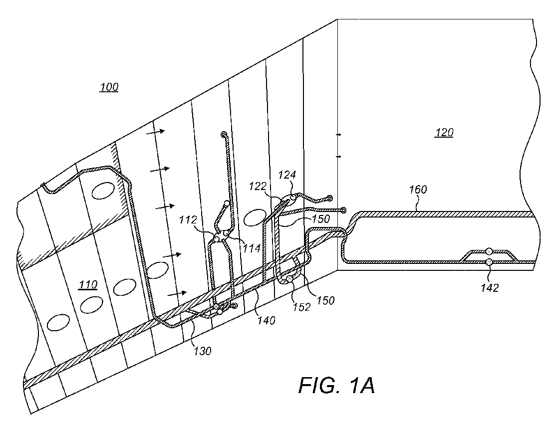
- a first aspect of the disclosed system and method comprises an improvement to an existing aircraft fuel system 100.
- the aircraft fuel system 100 includes a first main fuel tank or primary tank 110, which may be disposed within a wing as a so-called "wing tank,” and a second main fuel tank or auxiliary tank 120, which may be at least partially disposed within the aircraft's central fuselage as a so-called “center wing tank” or the like.
- the primary tank 110 includes at least a first boost fuel pump 112, and in typical variations may include a second boost fuel pump 114.
- the auxiliary tank 120 includes an override fuel pump 122 and, in a first embodiment, also includes a jettison fuel pump 124.
- a fuel manifold 130 interconnects the primary and auxiliary tanks 110, 120 with an aircraft engine (not shown), with the first and second boost fuel pumps 112, 114 being fluidly connected to the fuel manifold 130 to deliver primary fuel to the aircraft engine, and the override fuel pump 122 being fluidly connected through a check valve to the fuel manifold 130 to deliver auxiliary fuel to the aircraft engine.
- the boost fuel pump 112 (and 114, if present) and the override fuel pump 122 may be connected to a cross-feed manifold portion 140, with the cross-feed manifold portion 140 including at least one cross-feed valve 142 to divide the fuel system 100 into interconnectable subsystems, such as left and right subsystems.
- Jettison fuel pump 124 may be a component of a pre-existing, fully-installed jettison system 150, shown in Figures 1A and 1B , which typically includes a jettison transfer valve 152 fluidly connected to the jettison fuel pump 124, a jettison nozzle valve 154 fluidly connected to the jettison transfer valve 152, and a jettison nozzle 156 fluidly connected to the jettison nozzle valve 154.
- the jettison nozzle 156 is typically disposed near the trailing edge of the aircraft wing, with the jettison system 150 being manually activated in order to bring the aircraft below its maximum safe landing weight in the event that a flight must land soon after a heavily-laden takeoff.
- jettison fuel pump 124 functions as an override fuel pump assist, lowering the risk of incomplete override by decreasing pressure losses at high fuel flow rates and, in particular, increasing fuel pressure proximate the boost fuel pumps.
- the aircraft fuel system 100 is operated according to the following steps:
- the sensing step 210 may be automated using an engine monitoring circuit 300 such as an "engine speed card.”
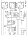
- Figure 3A shows a schematic diagram of an exemplary engine monitoring circuit 300 from a Boeing 767 series aircraft.
- An engine speed sensor 310 detects the rotor speed of an N2 rotor in the aircraft engine.
- the engine speed sensor 310 is operatively connected to a comparator 320 having a hysteresis filter which triggers at 83% of the maximum rated rotor speed of the N2 rotor of the aircraft engine for generally increasing speeds, and untriggers at 72% of the maximum rated rotor speed of the N2 rotor of the aircraft engine for generally decreasing speeds.
- the comparator drives a control relay 330, which provides an on/off signal output 340 to a fuel system control circuit 400 as further described below.
- the control relay 330 obtains signal power from the jettison system control circuitry and, more specifically, from a power supply lead within the jettison system control panel 402 (as shown in Fig. 3B ).
- signal power may be obtained from a variety of sources within the aircraft.
- second step 220 the method upon sensing that the aircraft engine is operating near maximum power, operating a jettison fuel pump 124 in fluid interconnection with the override fuel pump 122 to fuel the aircraft engine.
- the condition is of course based upon whether the aircraft engine speed is above the predetermined threshold, while in the aforementioned second variation, the condition is based upon whether the aircraft engine throttle setting is above the predetermined threshold.
- the operating step 230 omits any jettisoning operation of the jettison transfer valve 152 and the jettison nozzle valve 154 so that operation of the jettison fuel pump 124 delivers fuel to the fuel manifold 130.
- the operating step may require the opening of one or more other transfer valves to place the jettison fuel pump 124 in fluid communication with the override fuel pump 122, either directly or indirectly through the fuel manifold 130, . e.g ., through the cross-feed manifold portion 140, in order to configure the fuel system for override assist.
- the operating step 220 may be automated using a fuel system control circuit 400 which otherwise operates the jettison system 150.
- Figure 3B shows a schematic diagram of an exemplary jettison fuel pump control circuit 400 from a Boeing 767 series aircraft.
- the signal output 340 from control relay 330 (shown Fig. 3A ) operates a first operating relay 410 operatively connected to a jettison fuel pump enable circuit portion 420, which operatively controls the jettison fuel pump 124 (shown as a functional block for reference purposes).
- the first operating relay 410 is operatively connected to an input of an electrical load shedding portion 422 of the jettison fuel pump enable circuit portion 420 and to an input of a GFI portion 424 of the jettison fuel pump enable circuit portion 420, with the latter operatively controlling the jettison fuel pump 124.
- the first operating relay 410 passes the signal output 340 to the inputs of the portions 422 and 424 when operated by the signal output 340.
- the first operating relay 410 and the jettison fuel pump enable circuit portion 420 may be configured in various manners, so long as the combined first operating relay 410 and jettison fuel pump enable circuit portion 420 operatively controls the jettison fuel pump 124.
- the signal output 340 from control relay 330 may also operate a second operating relay 430 operatively connected to the jettison fuel pump enable circuit portion 420.
- the second operating relay 430 is operatively connected to the input of the GFI interrupter portion 424 of the jettison fuel pump enable circuit portion 420, providing a path to ground for the signal output 340 passed to this input, but only when the second operating relay 430 is operated by the signal output 340.
- third step 230 upon sensing that the aircraft engine has ceased operating near maximum power, deactivating the jettison fuel pump 124.
- the condition is based upon whether the aircraft engine speed drops below the predetermined threshold
- the condition is based upon whether the aircraft engine throttle setting drops below the predetermined threshold.
- the deactivation step occurs after the engine speed drops below the 83% threshold.
- the deactivation step may be delayed by a predetermined period of time after sensing that the aircraft engine speed has dropped below the first predetermined threshold.
- a predetermined period of time may be used in place of a hysteresis filter to prevent transitory changes in aircraft engine speed from causing the deactivation of the jettison fuel pump 124.
- the deactivating step occurs after the aircraft engine speed drops below the second rotor speed of the hysteresis filter.
- the deactivating step occurs after the aircraft engine speed has dropped below the 72% level of the hysteresis filter.
- the deactivating step occurs after the aircraft engine throttle setting drops below the predetermined threshold (in the corresponding specific example, below about 83% of maximum throttle of the aircraft engine) or the lower level of the hysteresis filter of the predetermined threshold (in the corresponding specific example, below the about 72% level of the hysteresis filter), as the case may be.
- the deactivation step may again be delayed by a predetermined period of time after sensing that the aircraft engine throttle setting has dropped below the first predetermined threshold in place of the use of a hysteresis filter.
- the deactivating step 230 omits any operation of the jettison transfer valve 152 and the jettison nozzle valve 154; however, in variations of the third step as applied to other aircraft, the deactivating step may require the closing of one or more transfer valves to remove the jettison fuel pump 124 from fluid interconnection with the override fuel pump 122 and/or the fuel manifold 130 in order to return to a standby configuration or to reconfigure the jettison system 150 for potential fuel jettisoning.
- the deactivating step 230 may be automated using the engine monitoring circuit 300 and fuel system control circuit 400 previously described in the context of the sensing step 210 and the operating step 220.
- the engine speed sensor 310 is operatively connected to the comparator 320 and, in the exemplary circuit illustrated in Fig. 3A , a hysteresis filter which untriggers at about 72% of the maximum rated rotor speed of the N2 rotor of the aircraft engine for generally decreasing speeds.
- the comparator drives the control relay 330 to switch off the signal output 340 to the fuel system control circuit 400. This deactivates the first operating relay 410 and jettison fuel pump enable circuit portion 420.
- the first operating relay 410 deactivates both the electrical load shedding portion 422 of the jettison fuel pump enable circuit portion 420 and the GFI interrupter portion 424 of the jettison fuel pump enable circuit portion 420, with the latter causing the deactivation of the jettison fuel pump 124.
- the switching off of the signal output 340 also deactivates the second operating relay 430, which disconnects the GFI interrupter portion 424 of the jettison fuel pump enable circuit portion 420 from ground.
- the aircraft fuel system 100 may lack a pre-existing jettison system 150.
- jettison systems are a customer option, and include many twin-engine "regional jets" capable of meeting FAA Landing Climb and Approach Climb regulations in lower capacity configurations.
- the second main tank 120 will include an override fuel pump 122 and, in a second embodiment, design provision for an optional jettison fuel pump 124.
- the aircraft fuel system control circuit may also, in the second embodiment, include pre-existing jettison system valve control circuitry 400 or design provision for optional jettison system valve control circuitry 400 through a daughterboard, external signal and power bus, or the like.
- the aircraft fuel system control circuit may be upgradable to an optional aircraft fuel system control circuit including a partially or fully populated jettison control circuit.
- the aircraft fuel system 100 may subsequently be retrofitted to partially install a jettison system 150 including at least a jettison fuel pump 124 in fluid communication with the override fuel pump 122.
- a jettison system 150 including at least a jettison fuel pump 124 in fluid communication with the override fuel pump 122.
- the jettison transfer valve 152, jettison nozzle valve 154, and jettison nozzle 156 may be omitted, along with other portions of the jettison system which are unique to that system such as jettisoning extensions to the aircraft refueling manifold 160 (which serves to distribute fuel to the main tanks during ground refueling operations as well as to deliver fuel to the jettison nozzle valve 154 and jettison nozzle 156 during jettisoning operations).
- the optional jettison fuel pump 124 would be fluidly connected to the fuel manifold 130 but not fluidly connected to the aircraft refueling manifold 160, serving only as an override fuel pump assist.
- the equipment which can be omitted from a retrofit installation of the override fuel pump assist will vary depending upon the design of the jettison system 150 in each particular type of aircraft, and that additional manifold structure such as a fuel manifold extension and check valve may be required to connect the optional jettison fuel pump 124 to the fuel manifold 130 depending upon the configuration of the optional jettison system in that type of aircraft.
- the fuel system control circuit 400 is also subsequently be retrofitted to add at least the first operating relay 410 as described above.
- the retrofitted fuel system control circuit 400 also includes the jettison fuel pump enable circuit portion 420 and second operating relay 430 described above. This may require a modification of pre-existing jettison system valve control circuitry or a modification of a pre-designed jettison system valve control circuit provided as daughterboard or bus-connected accessory board, etc.
- the fuel system control circuit 400 may be upgraded to a circuit including an at least partially populated jettison control circuit that includes at least the jettison fuel pump enable circuit portion 420 and the first operating relay 410.
- the retrofitted aircraft may subsequently be operated in accordance with the method described in the context of the first aspect.
- Automation of the method is substantially the same as that described in the context of the first aspect, although particulars such as the omission of any operation of a jettison transfer valve and jettison nozzle valve may be superfluous due to the potential absence of these structures in a retrofitted installation.
- a method for supplementing fuel feed pressure and flow within an aircraft fuel system fueling an aircraft engine includes a primary fuel tank, a first boost fuel pump delivering fuel from the primary tank to a fuel manifold, an auxiliary fuel tank, an override fuel pump delivering fuel from the auxiliary fuel tank to the fuel manifold, and a jettison fuel pump operable to draw fuel from the auxiliary fuel tank, and the method comprises the steps of:
- the jettison fuel pump is a component of a fully-installed jettison system including a jettison transfer valve and a jettison nozzle valve, and the operating step omits any jettisoning operation of the jettison transfer valve and the jettison nozzle valve.
- the jettison fuel pump is a component of a partially-installed jettison system, and the jettison fuel pump functions only as an override fuel pump assist.
- the sensing step senses whether the aircraft engine speed is above a first predetermined threshold.
- the predetermined threshold is a rotor speed of an N2 rotor of the aircraft engine.
- the predetermined threshold includes a hysteresis filter having a first rotor speed of an N2 rotor for generally increasing rotor speeds and a second rotor speed of the N2 rotor for generally decreasing rotor speeds, where the first rotor speed is greater than the second rotor speed.
- the deactivation step is delayed by a predetermined period of time upon sensing that the aircraft engine speed has dropped below the first predetermined threshold.
- the sensing step senses whether the aircraft engine throttle setting is above a first predetermined threshold.
- the predetermined threshold includes a hysteresis filter having a first aircraft engine throttle setting for generally increasing throttle settings and a second aircraft engine throttle setting for generally decreasing throttle settings, where the first aircraft engine throttle setting is greater than the second aircraft engine throttle setting.
- the deactivation step is delayed by a predetermined period of time upon sensing that the aircraft engine throttle setting has dropped below the first predetermined threshold.
- an override-based aircraft fuel system for fueling an aircraft engine
- the aircraft fuel system comprises a fuel manifold; a primary fuel tank including a first boost fuel pump fluidly connected to the fuel manifold; an auxiliary fuel tank including an override fuel pump fluidly connected to the fuel manifold and a jettison fuel pump fluidly connectable to the fuel manifold; an engine monitoring circuit including (a) an aircraft engine speed sensor operatively connected to a comparator and (b) a control relay selectively providing a signal output, wherein the comparator is configured to drive the control relay to provide the signal output when the aircraft engine speed sensor detects an aircraft engine speed greater than a predetermined threshold; and a fuel system control circuit including a first operating relay operatively connected to a jettison fuel pump enable circuit portion, wherein the signal output operates the first operating relay and the jettison fuel pump enable circuit portion, and wherein the jettison fuel pump enable circuit portion operatively controls the jettison fuel pump to deliver fuel to the fuel
- system disclosed above further comprises a jettison transfer valve fluidly connected the jettison fuel pump, wherein the fuel system control circuit is configured to operate the jettison fuel pump enable circuit portion and jettison fuel pump without operating the jettison transfer valve so as to permit the jettisoning of fuel.
- the engine speed sensor senses a rotor speed of an N2 rotor of the aircraft engine.
- the predetermined threshold of the comparator includes a hysteresis filter having a first rotor speed of an N2 rotor for generally increasing rotor speeds and a second rotor speed of the N2 rotor for generally decreasing rotor speeds, where the first rotor speed is greater than the second rotor speed.
- the first rotor speed is about 83% of the maximum rated rotor speed of the N2 rotor of the aircraft engine and the second rotor speed is about 72% of the maximum rated rotor speed of the N2 rotor of the aircraft engine.
- the fuel system control circuit includes a second operating relay operatively connected to the jettison fuel pump enable circuit portion, and wherein the signal output operates the second operating relay to provide a path to ground for the signal output operating the jettison fuel pump enable circuit portion
Landscapes
- Engineering & Computer Science (AREA)
- Chemical & Material Sciences (AREA)
- Combustion & Propulsion (AREA)
- Mechanical Engineering (AREA)
- General Engineering & Computer Science (AREA)
- Aviation & Aerospace Engineering (AREA)
- Cooling, Air Intake And Gas Exhaust, And Fuel Tank Arrangements In Propulsion Units (AREA)
Abstract
Description
- The present disclosure is directed to systems and methods for the distribution of fuel within a jet aircraft and, in particular, to systems and methods for supplementing fuel feed pressure and flow within a jet aircraft having multiple fuel tanks.
- Large, multiple engine jet aircraft typically have a fuel system which includes multiple fuel tanks in order to provide long-haul capability while maintaining a proper distribution of weight. In the case of a Boeing 767-300, the aircraft has a primary fuel tank or "wing tank" holding up to 18,500 kgs of fuel in each of the aircraft's wings, and a single auxiliary fuel tank or "center wing tank" holding up to 36,500 kgs of fuel in the aircraft's center wing box. The fuel tanks are fluidly connected to the aircraft's twin engines by a fuel manifold, with the wing tanks and the center wing tank being fluidly connected to the fuel manifold through a cross-feed manifold portion running through the center wing box. This cross-feed manifold portion is divided into two halves by at least one cross-feed valve, with the center wing tank being fluidly connected to both halves of the cross-feed manifold portion in order to create two operationally separate, yet selectively interconnectable, multiple tank subsystems for distributing fuel to the engines.
- Fuel is pumped from the primary and auxiliary fuel tanks into the fuel manifold by a plurality of fuel pumps. In the case of a Boeing 767-300, each wing tank includes two low pressure boost fuel pumps, both of which are fluidly connected to the same half of the cross-feed manifold portion for sake of redundancy, while the center wing tank includes two high pressure fuel pumps, each of which is fluidly connected to a different half of the cross-feed manifold portion in order to permit independent auxiliary fueling of the aircraft engines. In most aircraft fuel systems, and under ordinary conditions, the auxiliary tank is operated in an override mode, meaning that the low pressure boost fuel pumps in a primary tank remain active regardless of whether fuel is to be drawn from the primary tank or the auxiliary tank. When fuel is to be drawn from the auxiliary tank, a high pressure fuel pump or "override fuel pump" is activated to deliver fuel to the fuel manifold at a greater pressure than the low pressure boost fuel pumps can generate, overriding the flow of fuel from the boost fuel pumps into the fuel manifold and, in effect, de-selecting the primary tank. On the other hand, when fuel is to be drawn from the primary tank, then the override fuel pump is deactivated, and the flow of fuel from the boost fuel pumps into the fuel manifold resumes. In short, in an override-based aircraft fuel system, the system will include both low pressure boost fuel pumps and high pressure override fuel pumps, with the boost fuel pumps remaining active in order to prevent an interruption in fuel flow which could result in an engine flameout, and fuel manifold pressure controlling whether fuel will be drawn from a particular fuel tank.
- In some aircraft, factors such as the specific performance capabilities of the installed boost and override fuel pumps, the backpressure profile of the fuel manifold, and the suction pressure generated by an aircraft engine's own fuel pumps can diminish the fuel pressure proximate the boost fuel pumps and cause an "incomplete override" of one or more of the pumps, allowing fuel to be unintentionally drawn from a primary fuel tank, e.g., a wing tank, rather than an auxiliary fuel tank, e.g., a center wing tank. Such a situation may occur, for example, if an engine is operating near maximum power during the aircraft's initial climb and one of the installed boost fuel pumps is capable of pumping at greater-than-average pressures due to pump-to-pump manufacturing variations. Because the amount of fuel drawn from various fuel tanks will vary in an incomplete override scenario depending upon the individual performance capabilities of the fuel pumps, fuel may be drawn unevenly from the aircraft's fuel tanks, adversely affecting the aircraft's distribution of weight, in addition to contravening flight practices which require that auxiliary fuel supplies be essentially exhausted before switching over to primary fuel supplies. This unplanned and, likely, uneven fuel draw may require frequent adjustments to aircraft trim and repeated rebalancing of the aircraft's fuel load, increasing both pilot workload and opportunities for the risks associated with in-flight fuel transfers to become manifest.
- The applicant has developed a system and method for supplementing fuel feed pressure and flow without requiring the replacement of existing fuel pumps in existing aircraft, the replacement of existing fuel pump designs in existing aircraft designs, and the like. The disclosed system and method enable the automatic control of a multi-tank, multi-pump, override-based aircraft fuel system using pre-existing fuel pumps or fuel pump designs, in combination with novel modifications to the aircraft's engine monitoring circuity and fuel system control circuitry, in order to assist the override fuel pump. The system and method thus mitigate a risk of incomplete override with substantially reduced engineering cost and, potentially, substantially reduced maintenance costs and out-of-service delays.
- In one form, a method is disclosed for supplementing fuel feed pressure and flow within an aircraft fuel system fueling an aircraft engine. The aircraft fuel system includes a primary fuel tank, a first boost fuel pump delivering fuel from the primary tank to a fuel manifold, an auxiliary fuel tank, an override fuel pump delivering fuel from the auxiliary tank to the fuel manifold, and a jettison fuel pump operable to draw fuel from the auxiliary fuel tank. The method includes the steps of: (a) sensing whether the aircraft engine is operating near maximum power; (b) upon sensing that the aircraft engine is operating near maximum power, operating the jettison fuel pump in fluid interconnection with the override fuel pump to deliver fuel to the fuel manifold; and (c) upon sensing that the aircraft engine has ceased to operate near maximum power, deactivating the jettison fuel pump. The jettison fuel pump may be a component of a fully-installed jettison system, with the operating step omitting any jettisoning operation of a jettisoning valve, or may be a component of a partially-installed jettison system, with the jettison fuel pump functioning only as an override fuel pump assist.
- In another form, an override-based aircraft fuel system includes a fuel manifold, a primary fuel tank having a first boost fuel pump fluidly connected to the fuel manifold, and an auxiliary fuel tank having both an override fuel pump, fluidly connected to the fuel manifold, and a jettison fuel pump, fluidly connectable to the fuel manifold. The fuel system further includes an engine monitoring circuit including (a) an aircraft engine speed sensor operatively connected to a comparator and (b) a control relay selectively providing a signal output, with the comparator and control relay providing the signal output when the aircraft engine speed sensor detects an aircraft engine speed greater than a predetermined threshold. The signal output is communicated to a fuel system control circuit including a first operating relay operatively connected to a jettison fuel pump enable circuit portion, where the signal output operates the first operating relay and the jettison fuel pump enable circuit portion to operatively control the jettison fuel pump and deliver fuel to the fuel manifold.
-
-
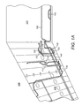
Fig. 1A is a first partial schematic diagram of an exemplary aircraft fuel system, joining toFig. 1B along the former figure's left edge. -
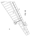
Fig. 1B is a second partial schematic diagram of an exemplary aircraft fuel system, joining toFig. 1A along the former figure's right edge. -
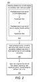
Fig. 2 is a block diagram of an aspect of the disclosed method. -
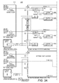
Fig. 3A is a partial schematic diagram of an exemplary aircraft engine monitoring circuit, also commonly known as an "engine speed card." -
Fig. 3B is a partial schematic diagram of an exemplary aircraft fuel system control circuit including jettison system valve control circuitry. - With initial reference to
Figure 1A , a first aspect of the disclosed system and method comprises an improvement to an existingaircraft fuel system 100. Theaircraft fuel system 100 includes a first main fuel tank orprimary tank 110, which may be disposed within a wing as a so-called "wing tank," and a second main fuel tank orauxiliary tank 120, which may be at least partially disposed within the aircraft's central fuselage as a so-called "center wing tank" or the like. Theprimary tank 110 includes at least a firstboost fuel pump 112, and in typical variations may include a secondboost fuel pump 114. Theauxiliary tank 120 includes anoverride fuel pump 122 and, in a first embodiment, also includes ajettison fuel pump 124. Afuel manifold 130 interconnects the primary andauxiliary tanks boost fuel pumps fuel manifold 130 to deliver primary fuel to the aircraft engine, and theoverride fuel pump 122 being fluidly connected through a check valve to thefuel manifold 130 to deliver auxiliary fuel to the aircraft engine. In multiple engine aircraft, the boost fuel pump 112 (and 114, if present) and theoverride fuel pump 122 may be connected to across-feed manifold portion 140, with thecross-feed manifold portion 140 including at least onecross-feed valve 142 to divide thefuel system 100 into interconnectable subsystems, such as left and right subsystems. As indicated in the brief description of the drawings, the right subsystem of thefuel system 100 shown inFigure 1 has been omitted, but it will be understood that the exemplary system being discussed herein is essentially bilaterally symmetric, with duplicate components and connections being provided for the two halves of the exemplary system. - Jettison
fuel pump 124 may be a component of a pre-existing, fully-installedjettison system 150, shown inFigures 1A and1B , which typically includes ajettison transfer valve 152 fluidly connected to thejettison fuel pump 124, ajettison nozzle valve 154 fluidly connected to thejettison transfer valve 152, and ajettison nozzle 156 fluidly connected to thejettison nozzle valve 154. Thejettison nozzle 156 is typically disposed near the trailing edge of the aircraft wing, with thejettison system 150 being manually activated in order to bring the aircraft below its maximum safe landing weight in the event that a flight must land soon after a heavily-laden takeoff. As shownFigure 1A , it is known to configure both theoverride fuel pump 122 and thejettison fuel pump 124 to deliver fuel to a common manifold for release through thejettison system 150, so that thejettison fuel pump 124 and theoverride fuel pump 122 may be used to jettison fuel at roughly twice the rate at which fuel would be jettisoned by thejettison fuel pump 124 alone. However, the applicant has determined that the combination of thejettison fuel pump 124 and theoverride fuel pump 122, with appropriate modifications to the aircraft's engine monitoring and fuel system control circuity, is also capable of delivering fuel through the check valve connection to thefuel manifold 130 at an increased rate sufficient to compensate for manufacturing variability in the capabilities of the boost fuel pump 112 (and 114, if present), the backpressure of thefuel manifold 130, the suction forces generated by the aircraft engine pumps, etc., and improve upon the pumphead capacity curve of theoverride fuel pump 122. In such an alternate mode,jettison fuel pump 124 functions as an override fuel pump assist, lowering the risk of incomplete override by decreasing pressure losses at high fuel flow rates and, in particular, increasing fuel pressure proximate the boost fuel pumps. - Referring now to
Figure 2 , in a method of supplementing fuel feed pressure and flow relating to the first aspect, theaircraft fuel system 100 is operated according to the following steps: - First, as shown in
step 210, the method may begin by sensing whether the aircraft engine is operating near maximum power. For the purposes of this application, the phrase "near maximum power" should be interpreted to mean 70% percent or more of maximum rated power. In a first variation ofstep 210, the sensing step senses whether the aircraft engine speed is above a predetermined threshold. In a first example of this first variation, the predetermined threshold is a rotor speed of an N2 or "intermediate pressure compressor" rotor of the aircraft engine. In a first specific example of this first variation, the predetermined threshold is about 83% of the maximum rated rotor speed of the N2 rotor of the aircraft engine. In a second example of this first variation, the predetermined threshold may include a hysteresis filter having a first rotor speed of an N2 rotor for generally increasing rotor speeds and a second rotor speed of the N2 rotor for generally decreasing rotor speeds, where the first rotor speed is greater than the second rotor speed. In a second specific example of this first variation, the first rotor speed is about 83% of the maximum rated rotor speed of the N2 rotor of the aircraft engine and the second rotor speed is about 72% of the maximum rated rotor speed of the N2 rotor of the aircraft engine. In a second variation ofstep 210, the sensing step senses whether the aircraft engine throttle setting is above a predetermined threshold. A similar simple value threshold or a similar threshold including a hysteresis filter may be implemented as examples of this second variation. A similar threshold of about 83% of maximum throttle of the aircraft engine or a similar hysteresis filter of 83% (increasing)/72% (decreasing) of maximum throttle of the aircraft engine may be implemented as specific examples of this second variation. - The sensing
step 210 may be automated using anengine monitoring circuit 300 such as an "engine speed card." For example,Figure 3A shows a schematic diagram of an exemplaryengine monitoring circuit 300 from a Boeing 767 series aircraft. Anengine speed sensor 310 detects the rotor speed of an N2 rotor in the aircraft engine. Theengine speed sensor 310 is operatively connected to acomparator 320 having a hysteresis filter which triggers at 83% of the maximum rated rotor speed of the N2 rotor of the aircraft engine for generally increasing speeds, and untriggers at 72% of the maximum rated rotor speed of the N2 rotor of the aircraft engine for generally decreasing speeds. The comparator drives acontrol relay 330, which provides an on/offsignal output 340 to a fuelsystem control circuit 400 as further described below. In one particular implementation, thecontrol relay 330 obtains signal power from the jettison system control circuitry and, more specifically, from a power supply lead within the jettison system control panel 402 (as shown inFig. 3B ). Those of skill in the art will of course recognize that signal power may be obtained from a variety of sources within the aircraft. - Returning to
Figure 2 , insecond step 220, the method upon sensing that the aircraft engine is operating near maximum power, operating ajettison fuel pump 124 in fluid interconnection with theoverride fuel pump 122 to fuel the aircraft engine. In the aforementioned first variation, the condition is of course based upon whether the aircraft engine speed is above the predetermined threshold, while in the aforementioned second variation, the condition is based upon whether the aircraft engine throttle setting is above the predetermined threshold. In general, the operatingstep 230 omits any jettisoning operation of thejettison transfer valve 152 and thejettison nozzle valve 154 so that operation of thejettison fuel pump 124 delivers fuel to thefuel manifold 130. However, in variations of the second step as applied to other aircraft, the operating step may require the opening of one or more other transfer valves to place thejettison fuel pump 124 in fluid communication with theoverride fuel pump 122, either directly or indirectly through thefuel manifold 130, .e.g., through the cross-feedmanifold portion 140, in order to configure the fuel system for override assist. - The operating
step 220 may be automated using a fuelsystem control circuit 400 which otherwise operates thejettison system 150. For example,Figure 3B shows a schematic diagram of an exemplary jettison fuelpump control circuit 400 from a Boeing 767 series aircraft. Thesignal output 340 from control relay 330 (shownFig. 3A ) operates afirst operating relay 410 operatively connected to a jettison fuel pump enablecircuit portion 420, which operatively controls the jettison fuel pump 124 (shown as a functional block for reference purposes). In one particular implementation, thefirst operating relay 410 is operatively connected to an input of an electricalload shedding portion 422 of the jettison fuel pump enablecircuit portion 420 and to an input of a GFI portion 424 of the jettison fuel pump enablecircuit portion 420, with the latter operatively controlling thejettison fuel pump 124. Thefirst operating relay 410 passes thesignal output 340 to the inputs of theportions 422 and 424 when operated by thesignal output 340. Those of skill in the art will of course recognize that thefirst operating relay 410 and the jettison fuel pump enablecircuit portion 420 may be configured in various manners, so long as the combinedfirst operating relay 410 and jettison fuel pump enablecircuit portion 420 operatively controls thejettison fuel pump 124. Thesignal output 340 fromcontrol relay 330 may also operate asecond operating relay 430 operatively connected to the jettison fuel pump enablecircuit portion 420. In the aforementioned particular implementation, thesecond operating relay 430 is operatively connected to the input of the GFI interrupter portion 424 of the jettison fuel pump enablecircuit portion 420, providing a path to ground for thesignal output 340 passed to this input, but only when thesecond operating relay 430 is operated by thesignal output 340. - Returning to
Figure 2 , inthird step 230, upon sensing that the aircraft engine has ceased operating near maximum power, deactivating thejettison fuel pump 124. Again, in the aforementioned first variation, the condition is based upon whether the aircraft engine speed drops below the predetermined threshold, while in the aforementioned second variation, the condition is based upon whether the aircraft engine throttle setting drops below the predetermined threshold. In a corresponding first specific example of the first variation, where the predetermined threshold is about 83% of the maximum rated rotor speed of the N2 rotor of the aircraft engine, the deactivation step occurs after the engine speed drops below the 83% threshold. In a modification of a corresponding first variation and/or the corresponding first specific example, the deactivation step may be delayed by a predetermined period of time after sensing that the aircraft engine speed has dropped below the first predetermined threshold. Such a predetermined period of time may be used in place of a hysteresis filter to prevent transitory changes in aircraft engine speed from causing the deactivation of thejettison fuel pump 124. - In a corresponding second example of the first variation, where the first predetermined threshold includes a hysteresis filter having a first rotor speed of an N2 rotor for generally increasing rotor speeds and a second rotor speed of the N2 rotor for generally decreasing rotor speeds, the deactivating step occurs after the aircraft engine speed drops below the second rotor speed of the hysteresis filter. In a corresponding second specific example of the first variation, where the first rotor speed is about 83% of the maximum rated rotor speed of the N2 rotor of the aircraft engine and the second rotor speed is about 72% of the maximum rated rotor speed of the N2 rotor of the aircraft engine, the deactivating step occurs after the aircraft engine speed has dropped below the 72% level of the hysteresis filter. In corresponding examples and specific examples of the second variation, the deactivating step occurs after the aircraft engine throttle setting drops below the predetermined threshold (in the corresponding specific example, below about 83% of maximum throttle of the aircraft engine) or the lower level of the hysteresis filter of the predetermined threshold (in the corresponding specific example, below the about 72% level of the hysteresis filter), as the case may be. In a modification of the second variation, the deactivation step may again be delayed by a predetermined period of time after sensing that the aircraft engine throttle setting has dropped below the first predetermined threshold in place of the use of a hysteresis filter.
- Again, in general, the deactivating
step 230 omits any operation of thejettison transfer valve 152 and thejettison nozzle valve 154; however, in variations of the third step as applied to other aircraft, the deactivating step may require the closing of one or more transfer valves to remove thejettison fuel pump 124 from fluid interconnection with theoverride fuel pump 122 and/or thefuel manifold 130 in order to return to a standby configuration or to reconfigure thejettison system 150 for potential fuel jettisoning. - The deactivating
step 230 may be automated using theengine monitoring circuit 300 and fuelsystem control circuit 400 previously described in the context of thesensing step 210 and the operatingstep 220. Theengine speed sensor 310 is operatively connected to thecomparator 320 and, in the exemplary circuit illustrated inFig. 3A , a hysteresis filter which untriggers at about 72% of the maximum rated rotor speed of the N2 rotor of the aircraft engine for generally decreasing speeds. The comparator drives thecontrol relay 330 to switch off thesignal output 340 to the fuelsystem control circuit 400. This deactivates thefirst operating relay 410 and jettison fuel pump enablecircuit portion 420. In the particular implementation previously described, thefirst operating relay 410 deactivates both the electricalload shedding portion 422 of the jettison fuel pump enablecircuit portion 420 and the GFI interrupter portion 424 of the jettison fuel pump enablecircuit portion 420, with the latter causing the deactivation of thejettison fuel pump 124. In that particular implementation, the switching off of thesignal output 340 also deactivates thesecond operating relay 430, which disconnects the GFI interrupter portion 424 of the jettison fuel pump enablecircuit portion 420 from ground. - In a second aspect of the disclosed system and method, the
aircraft fuel system 100 may lack apre-existing jettison system 150. Such configurations may exist where jettison systems are a customer option, and include many twin-engine "regional jets" capable of meeting FAA Landing Climb and Approach Climb regulations in lower capacity configurations. The secondmain tank 120 will include anoverride fuel pump 122 and, in a second embodiment, design provision for an optionaljettison fuel pump 124. The aircraft fuel system control circuit may also, in the second embodiment, include pre-existing jettison systemvalve control circuitry 400 or design provision for optional jettison systemvalve control circuitry 400 through a daughterboard, external signal and power bus, or the like. Alternately, the aircraft fuel system control circuit may be upgradable to an optional aircraft fuel system control circuit including a partially or fully populated jettison control circuit. - The
aircraft fuel system 100 may subsequently be retrofitted to partially install ajettison system 150 including at least ajettison fuel pump 124 in fluid communication with theoverride fuel pump 122. In aircraft such as the Boeing 767-300, where theoverride fuel pump 122 and jettisonfuel pump 124 are designed to discharge into a common manifold, thejettison transfer valve 152,jettison nozzle valve 154, andjettison nozzle 156 may be omitted, along with other portions of the jettison system which are unique to that system such as jettisoning extensions to the aircraft refueling manifold 160 (which serves to distribute fuel to the main tanks during ground refueling operations as well as to deliver fuel to thejettison nozzle valve 154 andjettison nozzle 156 during jettisoning operations). Thus, the optionaljettison fuel pump 124 would be fluidly connected to thefuel manifold 130 but not fluidly connected to theaircraft refueling manifold 160, serving only as an override fuel pump assist. Those of skill in the art will of course recognize that the equipment which can be omitted from a retrofit installation of the override fuel pump assist will vary depending upon the design of thejettison system 150 in each particular type of aircraft, and that additional manifold structure such as a fuel manifold extension and check valve may be required to connect the optionaljettison fuel pump 124 to thefuel manifold 130 depending upon the configuration of the optional jettison system in that type of aircraft. - The fuel
system control circuit 400 is also subsequently be retrofitted to add at least thefirst operating relay 410 as described above. In a variation, the retrofitted fuelsystem control circuit 400 also includes the jettison fuel pump enablecircuit portion 420 andsecond operating relay 430 described above. This may require a modification of pre-existing jettison system valve control circuitry or a modification of a pre-designed jettison system valve control circuit provided as daughterboard or bus-connected accessory board, etc. Alternately, the fuelsystem control circuit 400 may be upgraded to a circuit including an at least partially populated jettison control circuit that includes at least the jettison fuel pump enablecircuit portion 420 and thefirst operating relay 410. - The retrofitted aircraft may subsequently be operated in accordance with the method described in the context of the first aspect. Automation of the method is substantially the same as that described in the context of the first aspect, although particulars such as the omission of any operation of a jettison transfer valve and jettison nozzle valve may be superfluous due to the potential absence of these structures in a retrofitted installation.
- The various aspects, embodiments, implementations, and variations described above are intended to be illustrative in nature, and are not intended to limit the scope of the invention. In particular, the disclosed specific examples and figures, illustrating the systems used in a twin engine Boeing 767 aircraft, are intended to demonstrate a broader applicability to single or multiple engine jet aircraft in general. Any limitations to the invention will appear in the claims as allowed in view of the terms explicitly defined herein.
- According to one aspect disclosed herein, a method for supplementing fuel feed pressure and flow within an aircraft fuel system fueling an aircraft engine, the aircraft fuel system includes a primary fuel tank, a first boost fuel pump delivering fuel from the primary tank to a fuel manifold, an auxiliary fuel tank, an override fuel pump delivering fuel from the auxiliary fuel tank to the fuel manifold, and a jettison fuel pump operable to draw fuel from the auxiliary fuel tank, and the method comprises the steps of:
- (a) sensing whether the aircraft engine is operating near maximum power;
- (b) upon sensing that the aircraft engine is operating near maximum power, operating the jettison fuel pump in fluid interconnection with the override fuel pump to deliver fuel to the fuel manifold; and
- (c) upon sensing that the aircraft engine has ceased to operate near maximum power, deactivating the jettison fuel pump;
- Optionally, the jettison fuel pump is a component of a fully-installed jettison system including a jettison transfer valve and a jettison nozzle valve, and the operating step omits any jettisoning operation of the jettison transfer valve and the jettison nozzle valve.
- Optionally, the jettison fuel pump is a component of a partially-installed jettison system, and the jettison fuel pump functions only as an override fuel pump assist.
- Optionally, the sensing step senses whether the aircraft engine speed is above a first predetermined threshold.
- Optionally, the predetermined threshold is a rotor speed of an N2 rotor of the aircraft engine.
- Optionally, the predetermined threshold includes a hysteresis filter having a first rotor speed of an N2 rotor for generally increasing rotor speeds and a second rotor speed of the N2 rotor for generally decreasing rotor speeds, where the first rotor speed is greater than the second rotor speed.
- Optionally, the deactivation step is delayed by a predetermined period of time upon sensing that the aircraft engine speed has dropped below the first predetermined threshold.
- Optionally, the sensing step senses whether the aircraft engine throttle setting is above a first predetermined threshold.
- Optionally, the predetermined threshold includes a hysteresis filter having a first aircraft engine throttle setting for generally increasing throttle settings and a second aircraft engine throttle setting for generally decreasing throttle settings, where the first aircraft engine throttle setting is greater than the second aircraft engine throttle setting.
- Optionally, the deactivation step is delayed by a predetermined period of time upon sensing that the aircraft engine throttle setting has dropped below the first predetermined threshold.
- In another aspect disclosed herein, an override-based aircraft fuel system for fueling an aircraft engine, the aircraft fuel system comprises a fuel manifold; a primary fuel tank including a first boost fuel pump fluidly connected to the fuel manifold; an auxiliary fuel tank including an override fuel pump fluidly connected to the fuel manifold and a jettison fuel pump fluidly connectable to the fuel manifold; an engine monitoring circuit including (a) an aircraft engine speed sensor operatively connected to a comparator and (b) a control relay selectively providing a signal output, wherein the comparator is configured to drive the control relay to provide the signal output when the aircraft engine speed sensor detects an aircraft engine speed greater than a predetermined threshold; and a fuel system control circuit including a first operating relay operatively connected to a jettison fuel pump enable circuit portion, wherein the signal output operates the first operating relay and the jettison fuel pump enable circuit portion, and wherein the jettison fuel pump enable circuit portion operatively controls the jettison fuel pump to deliver fuel to the fuel manifold.
- Optionally, the system disclosed above further comprises a jettison transfer valve fluidly connected the jettison fuel pump, wherein the fuel system control circuit is configured to operate the jettison fuel pump enable circuit portion and jettison fuel pump without operating the jettison transfer valve so as to permit the jettisoning of fuel.
- Optionally, the engine speed sensor senses a rotor speed of an N2 rotor of the aircraft engine.
- Optionally, the predetermined threshold of the comparator includes a hysteresis filter having a first rotor speed of an N2 rotor for generally increasing rotor speeds and a second rotor speed of the N2 rotor for generally decreasing rotor speeds, where the first rotor speed is greater than the second rotor speed.
- Optionally, the first rotor speed is about 83% of the maximum rated rotor speed of the N2 rotor of the aircraft engine and the second rotor speed is about 72% of the maximum rated rotor speed of the N2 rotor of the aircraft engine.
- Optionally, the fuel system control circuit includes a second operating relay operatively connected to the jettison fuel pump enable circuit portion, and wherein the signal output operates the second operating relay to provide a path to ground for the signal output operating the jettison fuel pump enable circuit portion
Claims (15)
- A method for supplementing fuel feed pressure and flow within an aircraft fuel system (100) fueling an aircraft engine, the aircraft fuel system (100) including a primary fuel tank (110), a first boost fuel pump (112) delivering fuel from the primary tank (110) to a fuel manifold (130), an auxiliary fuel tank (120), an override fuel pump (112) delivering fuel from the auxiliary fuel tank (120) to the fuel manifold (130), and a jettison fuel pump (124) operable to draw fuel from the auxiliary fuel tank (120), and the method comprising the steps of:(a) sensing (210) whether the aircraft engine is operating near maximum power;(b) upon sensing (220) that the aircraft engine is operating near maximum power, operating the jettison fuel pump (124) in fluid interconnection with the override fuel pump (112) to deliver fuel to the fuel manifold (130); and(c) upon sensing(230) that the aircraft engine has ceased to operate near maximum power, deactivating (230) the jettison fuel pump (124);whereby operation of the jettison fuel pump (124) in combination with the override fuel pump (112) completely overrides fuel delivery by the first boost fuel pump (112) from the primary fuel tank (110) to the fuel manifold (130).
- The method of claim 1, wherein the jettison fuel pump (124) is a component of a fully-installed jettison system (150) including a jettison transfer valve (152) and a jettison nozzle valve (154), and the operating step omits any jettisoning operation of the jettison transfer valve (152) and the jettison nozzle valve (154).
- The method of claim 1, wherein the jettison fuel pump (124) is a component of a partially-installed jettison system, and the jettison fuel pump (124) functions only as an override fuel pump (122) assist.
- The method of claim 1, wherein the sensing step (210) senses whether the aircraft engine speed is above a first predetermined threshold.
- The method of claim 4, wherein the predetermined threshold is a rotor speed of an N2 rotor of the aircraft engine.
- The method of claim 5, wherein the predetermined threshold includes a hysteresis filter having a first rotor speed of an N2 rotor for generally increasing rotor speeds and a second rotor speed of the N2 rotor for generally decreasing rotor speeds, where the first rotor speed is greater than the second rotor speed.
- The method of claim 4, wherein the deactivation step (230) is delayed by a predetermined period of time upon sensing that the aircraft engine speed has dropped below the first predetermined threshold.
- The method of claim 1, wherein the sensing step (210) senses whether the aircraft engine throttle setting is above a first predetermined threshold.
- The method of claim 8, wherein the predetermined threshold includes a hysteresis filter having a first aircraft engine throttle setting for generally increasing throttle settings and a second aircraft engine throttle setting for generally decreasing throttle settings, where the first aircraft engine throttle setting is greater than the second aircraft engine throttle setting.
- The method of claim 8, wherein the deactivation step is delayed by a predetermined period of time upon sensing that the aircraft engine throttle setting has dropped below the first predetermined threshold.
- An override-based aircraft fuel system for fueling an aircraft engine, the aircraft fuel system comprising:a fuel manifold (130);a primary fuel tank (110) including a first boost fuel pump (112) fluidly connected to the fuel manifold (130);an auxiliary fuel tank (120) including an override fuel pump (122) fluidly connected to the fuel manifold (130) and a jettison fuel pump (124) fluidly connectable to the fuel manifold (124);an engine monitoring circuit (300) including (a) an aircraft engine speed sensor (310) operatively connected to a comparator (320) and (b) a control relay (330) selectively providing a signal output, wherein the comparator (300) is configured to drive the control relay (330) to provide the signal output when the aircraft engine speed sensor (310) detects an aircraft engine speed greater than a predetermined threshold; anda fuel system control circuit (400) including a first operating relay (410) operatively connected to a jettison fuel pump enable circuit portion (420), wherein the signal output operates the first operating relay (410) and the jettison fuel pump enable circuit portion (420), and wherein the jettison fuel pump enable circuit portion (420) operatively controls the jettison fuel pump (124) to deliver fuel to the fuel manifold (130).
- The override-based aircraft fuel system of claim 11, further comprising a jettison transfer valve (152) fluidly connected the jettison fuel pump (124), wherein the fuel system control circuit (400) is configured to operate the jettison fuel pump enable circuit portion (420) and jettison fuel pump (124) without operating the jettison transfer valve (152) so as to permit the jettisoning of fuel.
- The override-based aircraft fuel system of any of claims 11-12, wherein the engine speed sensor (310) senses a rotor speed of an N2 rotor of the aircraft engine.
- The override-based aircraft fuel system of claim 13, wherein the predetermined threshold of the comparator (320) includes a hysteresis filter having a first rotor speed of an N2 rotor for generally increasing rotor speeds and a second rotor speed of the N2 rotor for generally decreasing rotor speeds, where the first rotor speed is greater than the second rotor speed.
- The override-based aircraft fuel system of claim 14 , wherein the first rotor speed is about 83% of the maximum rated rotor speed of the N2 rotor of the aircraft engine and the second rotor speed is about 72% of the maximum rated rotor speed of the N2 rotor of the aircraft engine.
Applications Claiming Priority (2)
| Application Number | Priority Date | Filing Date | Title |
|---|---|---|---|
| US13/229,751 US8950186B2 (en) | 2011-09-11 | 2011-09-11 | Speed card-controlled override fuel pump assist |
| EP12183889 | 2012-09-11 |
Related Parent Applications (2)
| Application Number | Title | Priority Date | Filing Date |
|---|---|---|---|
| EP12183889 Division | 2011-09-11 | 2012-09-11 | |
| EP12183889.0 Division | 2012-09-11 |
Publications (3)
| Publication Number | Publication Date |
|---|---|
| EP2612815A2 true EP2612815A2 (en) | 2013-07-10 |
| EP2612815A3 EP2612815A3 (en) | 2014-07-30 |
| EP2612815B1 EP2612815B1 (en) | 2017-04-19 |
Family
ID=46826343
Family Applications (1)
| Application Number | Title | Priority Date | Filing Date |
|---|---|---|---|
| EP13151085.1A Not-in-force EP2612815B1 (en) | 2011-09-11 | 2012-09-11 | Speed card-controlled override fuel pump assist |
Country Status (2)
| Country | Link |
|---|---|
| US (2) | US8950186B2 (en) |
| EP (1) | EP2612815B1 (en) |
Families Citing this family (5)
| Publication number | Priority date | Publication date | Assignee | Title |
|---|---|---|---|---|
| CN104960670B (en) * | 2015-06-23 | 2017-04-19 | 中国航空工业集团公司西安飞机设计研究所 | Residual-oil discharging method for ventilation cabinet of fuel system of negative dihedral wing of large aircraft |
| US10647196B2 (en) * | 2017-08-11 | 2020-05-12 | Z4 Manufacturing, Inc. | Auxiliary fuel tank control systems and methods of use |
| US11485513B2 (en) * | 2018-10-05 | 2022-11-01 | Parker-Hannifin Corporation | Fuel pump override control method |
| CN114183253B (en) * | 2021-12-29 | 2024-09-17 | 石家庄飞机工业有限责任公司 | Control device of automatic fuel oil supply system of small general aircraft |
| US12270344B2 (en) | 2023-08-28 | 2025-04-08 | Hamilton Sundstrand Corporation | Controllable fuel nozzle valves with redundancy |
Family Cites Families (5)
| Publication number | Priority date | Publication date | Assignee | Title |
|---|---|---|---|---|
| US3275061A (en) | 1964-01-02 | 1966-09-27 | Boeing Co | Fuel feeding systems |
| US4038817A (en) | 1975-06-02 | 1977-08-02 | General Electric Company | Fuel jettison system |
| US7458543B2 (en) * | 2005-06-10 | 2008-12-02 | The Boeing Company | Aerial refueling system |
| US7337795B2 (en) | 2005-10-17 | 2008-03-04 | The Boeing Company | Fuel balancing system |
| US7857260B2 (en) * | 2007-01-19 | 2010-12-28 | Sikorsky Aircraft Corporation | Fuel jettison system |
-
2011
- 2011-09-11 US US13/229,751 patent/US8950186B2/en not_active Expired - Fee Related
-
2012
- 2012-09-11 EP EP13151085.1A patent/EP2612815B1/en not_active Not-in-force
-
2015
- 2015-01-22 US US14/602,412 patent/US9732678B2/en not_active Expired - Fee Related
Non-Patent Citations (1)
| Title |
|---|
| None |
Also Published As
| Publication number | Publication date |
|---|---|
| US9732678B2 (en) | 2017-08-15 |
| US8950186B2 (en) | 2015-02-10 |
| US20130061595A1 (en) | 2013-03-14 |
| EP2612815B1 (en) | 2017-04-19 |
| EP2612815A3 (en) | 2014-07-30 |
| US20160169121A1 (en) | 2016-06-16 |
Similar Documents
| Publication | Publication Date | Title |
|---|---|---|
| US9732678B2 (en) | Speed card-controlled override fuel pump assist | |
| EP3232036B1 (en) | Dual pump fuel system with pump sharing connection | |
| US10669943B2 (en) | Fuel pumping arrangement for an aircraft engine | |
| US8256222B2 (en) | Direct metering fuel control with integral electrical metering pump and actuator servo pump | |
| US7337795B2 (en) | Fuel balancing system | |
| US8127548B2 (en) | Hybrid electrical/mechanical turbine engine fuel supply system | |
| EP2796688B1 (en) | System for controlling two positive displacement pumps | |
| EP2485109B1 (en) | Direct metering fuel system with constant servo flow | |
| CN111806706B (en) | Oil storage system suitable for airplane and emergency oil discharge method of system | |
| CA2922020A1 (en) | Fuel supply apparatus for aircraft engine | |
| US20080309261A1 (en) | Electric drive fuel control system and method | |
| CN101291847B (en) | Fuel system of mobile platform and method for balancing fuel level between fuel storage devices | |
| CN114954966B (en) | Aircraft fuel supply and fuel transfer system and method | |
| CN110712756B (en) | Aircraft and method for applying heat to a flight surface of an aircraft | |
| US8733398B2 (en) | Shut-down arrangement | |
| US11485513B2 (en) | Fuel pump override control method | |
| CN113799972A (en) | System and method for correcting fuel mass imbalance between left and right wings of an aircraft | |
| CN119102890A (en) | A fuel system for auxiliary power unit and control method thereof, and aircraft | |
| CN117703727A (en) | Control system and method for hydraulic direct-current electric pump of airplane | |
| US20130309091A1 (en) | Oil supply system for a propeller turbine engine | |
| CN120793183A (en) | Aerial oil supply and drain system and method for aircraft | |
| CN118124810A (en) | Unmanned aerial vehicle supplies oil transportation system |
Legal Events
| Date | Code | Title | Description |
|---|---|---|---|
| PUAI | Public reference made under article 153(3) epc to a published international application that has entered the european phase |
Free format text: ORIGINAL CODE: 0009012 |
|
| AK | Designated contracting states |
Kind code of ref document: A2 Designated state(s): AL AT BE BG CH CY CZ DE DK EE ES FI FR GB GR HR HU IE IS IT LI LT LU LV MC MK MT NL NO PL PT RO RS SE SI SK SM TR |
|
| AX | Request for extension of the european patent |
Extension state: BA ME |
|
| RIN1 | Information on inventor provided before grant (corrected) |
Inventor name: MCCABE, MR. WILLIAM H. |
|
| PUAL | Search report despatched |
Free format text: ORIGINAL CODE: 0009013 |
|
| AK | Designated contracting states |
Kind code of ref document: A3 Designated state(s): AL AT BE BG CH CY CZ DE DK EE ES FI FR GB GR HR HU IE IS IT LI LT LU LV MC MK MT NL NO PL PT RO RS SE SI SK SM TR |
|
| AX | Request for extension of the european patent |
Extension state: BA ME |
|
| RIC1 | Information provided on ipc code assigned before grant |
Ipc: F02C 7/236 20060101ALI20140626BHEP Ipc: F02C 9/28 20060101ALI20140626BHEP Ipc: B64D 37/28 20060101AFI20140626BHEP |
|
| 17P | Request for examination filed |
Effective date: 20141224 |
|
| RBV | Designated contracting states (corrected) |
Designated state(s): AL AT BE BG CH CY CZ DE DK EE ES FI FR GB GR HR HU IE IS IT LI LT LU LV MC MK MT NL NO PL PT RO RS SE SI SK SM TR |
|
| GRAP | Despatch of communication of intention to grant a patent |
Free format text: ORIGINAL CODE: EPIDOSNIGR1 |
|
| RIC1 | Information provided on ipc code assigned before grant |
Ipc: F02C 9/28 20060101ALI20161010BHEP Ipc: B64D 37/28 20060101AFI20161010BHEP Ipc: F02C 7/236 20060101ALI20161010BHEP |
|
| INTG | Intention to grant announced |
Effective date: 20161110 |
|
| GRAS | Grant fee paid |
Free format text: ORIGINAL CODE: EPIDOSNIGR3 |
|
| GRAA | (expected) grant |
Free format text: ORIGINAL CODE: 0009210 |
|
| AK | Designated contracting states |
Kind code of ref document: B1 Designated state(s): AL AT BE BG CH CY CZ DE DK EE ES FI FR GB GR HR HU IE IS IT LI LT LU LV MC MK MT NL NO PL PT RO RS SE SI SK SM TR |
|
| REG | Reference to a national code |
Ref country code: GB Ref legal event code: FG4D |
|
| REG | Reference to a national code |
Ref country code: CH Ref legal event code: EP |
|
| REG | Reference to a national code |
Ref country code: AT Ref legal event code: REF Ref document number: 885677 Country of ref document: AT Kind code of ref document: T Effective date: 20170515 |
|
| REG | Reference to a national code |
Ref country code: IE Ref legal event code: FG4D |
|
| REG | Reference to a national code |
Ref country code: DE Ref legal event code: R096 Ref document number: 602012031517 Country of ref document: DE |
|
| REG | Reference to a national code |
Ref country code: NL Ref legal event code: MP Effective date: 20170419 |
|
| REG | Reference to a national code |
Ref country code: LT Ref legal event code: MG4D |
|
| REG | Reference to a national code |
Ref country code: AT Ref legal event code: MK05 Ref document number: 885677 Country of ref document: AT Kind code of ref document: T Effective date: 20170419 |
|
| REG | Reference to a national code |
Ref country code: FR Ref legal event code: PLFP Year of fee payment: 6 |
|
| PG25 | Lapsed in a contracting state [announced via postgrant information from national office to epo] |
Ref country code: NL Free format text: LAPSE BECAUSE OF FAILURE TO SUBMIT A TRANSLATION OF THE DESCRIPTION OR TO PAY THE FEE WITHIN THE PRESCRIBED TIME-LIMIT Effective date: 20170419 |
|
| PG25 | Lapsed in a contracting state [announced via postgrant information from national office to epo] |
Ref country code: NO Free format text: LAPSE BECAUSE OF FAILURE TO SUBMIT A TRANSLATION OF THE DESCRIPTION OR TO PAY THE FEE WITHIN THE PRESCRIBED TIME-LIMIT Effective date: 20170719 Ref country code: AT Free format text: LAPSE BECAUSE OF FAILURE TO SUBMIT A TRANSLATION OF THE DESCRIPTION OR TO PAY THE FEE WITHIN THE PRESCRIBED TIME-LIMIT Effective date: 20170419 Ref country code: GR Free format text: LAPSE BECAUSE OF FAILURE TO SUBMIT A TRANSLATION OF THE DESCRIPTION OR TO PAY THE FEE WITHIN THE PRESCRIBED TIME-LIMIT Effective date: 20170720 Ref country code: LT Free format text: LAPSE BECAUSE OF FAILURE TO SUBMIT A TRANSLATION OF THE DESCRIPTION OR TO PAY THE FEE WITHIN THE PRESCRIBED TIME-LIMIT Effective date: 20170419 Ref country code: FI Free format text: LAPSE BECAUSE OF FAILURE TO SUBMIT A TRANSLATION OF THE DESCRIPTION OR TO PAY THE FEE WITHIN THE PRESCRIBED TIME-LIMIT Effective date: 20170419 Ref country code: HR Free format text: LAPSE BECAUSE OF FAILURE TO SUBMIT A TRANSLATION OF THE DESCRIPTION OR TO PAY THE FEE WITHIN THE PRESCRIBED TIME-LIMIT Effective date: 20170419 Ref country code: ES Free format text: LAPSE BECAUSE OF FAILURE TO SUBMIT A TRANSLATION OF THE DESCRIPTION OR TO PAY THE FEE WITHIN THE PRESCRIBED TIME-LIMIT Effective date: 20170419 |
|
| PG25 | Lapsed in a contracting state [announced via postgrant information from national office to epo] |
Ref country code: IS Free format text: LAPSE BECAUSE OF FAILURE TO SUBMIT A TRANSLATION OF THE DESCRIPTION OR TO PAY THE FEE WITHIN THE PRESCRIBED TIME-LIMIT Effective date: 20170819 Ref country code: SE Free format text: LAPSE BECAUSE OF FAILURE TO SUBMIT A TRANSLATION OF THE DESCRIPTION OR TO PAY THE FEE WITHIN THE PRESCRIBED TIME-LIMIT Effective date: 20170419 Ref country code: LV Free format text: LAPSE BECAUSE OF FAILURE TO SUBMIT A TRANSLATION OF THE DESCRIPTION OR TO PAY THE FEE WITHIN THE PRESCRIBED TIME-LIMIT Effective date: 20170419 Ref country code: PL Free format text: LAPSE BECAUSE OF FAILURE TO SUBMIT A TRANSLATION OF THE DESCRIPTION OR TO PAY THE FEE WITHIN THE PRESCRIBED TIME-LIMIT Effective date: 20170419 Ref country code: RS Free format text: LAPSE BECAUSE OF FAILURE TO SUBMIT A TRANSLATION OF THE DESCRIPTION OR TO PAY THE FEE WITHIN THE PRESCRIBED TIME-LIMIT Effective date: 20170419 |
|
| REG | Reference to a national code |
Ref country code: DE Ref legal event code: R097 Ref document number: 602012031517 Country of ref document: DE |
|
| PG25 | Lapsed in a contracting state [announced via postgrant information from national office to epo] |
Ref country code: DK Free format text: LAPSE BECAUSE OF FAILURE TO SUBMIT A TRANSLATION OF THE DESCRIPTION OR TO PAY THE FEE WITHIN THE PRESCRIBED TIME-LIMIT Effective date: 20170419 Ref country code: CZ Free format text: LAPSE BECAUSE OF FAILURE TO SUBMIT A TRANSLATION OF THE DESCRIPTION OR TO PAY THE FEE WITHIN THE PRESCRIBED TIME-LIMIT Effective date: 20170419 Ref country code: SK Free format text: LAPSE BECAUSE OF FAILURE TO SUBMIT A TRANSLATION OF THE DESCRIPTION OR TO PAY THE FEE WITHIN THE PRESCRIBED TIME-LIMIT Effective date: 20170419 Ref country code: EE Free format text: LAPSE BECAUSE OF FAILURE TO SUBMIT A TRANSLATION OF THE DESCRIPTION OR TO PAY THE FEE WITHIN THE PRESCRIBED TIME-LIMIT Effective date: 20170419 |
|
| PLBE | No opposition filed within time limit |
Free format text: ORIGINAL CODE: 0009261 |
|
| STAA | Information on the status of an ep patent application or granted ep patent |
Free format text: STATUS: NO OPPOSITION FILED WITHIN TIME LIMIT |
|
| PG25 | Lapsed in a contracting state [announced via postgrant information from national office to epo] |
Ref country code: IT Free format text: LAPSE BECAUSE OF FAILURE TO SUBMIT A TRANSLATION OF THE DESCRIPTION OR TO PAY THE FEE WITHIN THE PRESCRIBED TIME-LIMIT Effective date: 20170419 Ref country code: SM Free format text: LAPSE BECAUSE OF FAILURE TO SUBMIT A TRANSLATION OF THE DESCRIPTION OR TO PAY THE FEE WITHIN THE PRESCRIBED TIME-LIMIT Effective date: 20170419 |
|
| 26N | No opposition filed |
Effective date: 20180122 |
|
| REG | Reference to a national code |
Ref country code: CH Ref legal event code: PL |
|
| PG25 | Lapsed in a contracting state [announced via postgrant information from national office to epo] |
Ref country code: SI Free format text: LAPSE BECAUSE OF FAILURE TO SUBMIT A TRANSLATION OF THE DESCRIPTION OR TO PAY THE FEE WITHIN THE PRESCRIBED TIME-LIMIT Effective date: 20170419 Ref country code: MC Free format text: LAPSE BECAUSE OF FAILURE TO SUBMIT A TRANSLATION OF THE DESCRIPTION OR TO PAY THE FEE WITHIN THE PRESCRIBED TIME-LIMIT Effective date: 20170419 |
|
| REG | Reference to a national code |
Ref country code: IE Ref legal event code: MM4A |
|
| REG | Reference to a national code |
Ref country code: BE Ref legal event code: MM Effective date: 20170930 |
|
| PG25 | Lapsed in a contracting state [announced via postgrant information from national office to epo] |
Ref country code: LU Free format text: LAPSE BECAUSE OF NON-PAYMENT OF DUE FEES Effective date: 20170911 |
|
| PG25 | Lapsed in a contracting state [announced via postgrant information from national office to epo] |
Ref country code: IE Free format text: LAPSE BECAUSE OF NON-PAYMENT OF DUE FEES Effective date: 20170911 Ref country code: CH Free format text: LAPSE BECAUSE OF NON-PAYMENT OF DUE FEES Effective date: 20170930 Ref country code: LI Free format text: LAPSE BECAUSE OF NON-PAYMENT OF DUE FEES Effective date: 20170930 |
|
| PG25 | Lapsed in a contracting state [announced via postgrant information from national office to epo] |
Ref country code: BE Free format text: LAPSE BECAUSE OF NON-PAYMENT OF DUE FEES Effective date: 20170930 |
|
| REG | Reference to a national code |
Ref country code: FR Ref legal event code: PLFP Year of fee payment: 7 |
|
| PG25 | Lapsed in a contracting state [announced via postgrant information from national office to epo] |
Ref country code: MT Free format text: LAPSE BECAUSE OF NON-PAYMENT OF DUE FEES Effective date: 20170911 |
|
| PG25 | Lapsed in a contracting state [announced via postgrant information from national office to epo] |
Ref country code: HU Free format text: LAPSE BECAUSE OF FAILURE TO SUBMIT A TRANSLATION OF THE DESCRIPTION OR TO PAY THE FEE WITHIN THE PRESCRIBED TIME-LIMIT; INVALID AB INITIO Effective date: 20120911 |
|
| PG25 | Lapsed in a contracting state [announced via postgrant information from national office to epo] |
Ref country code: BG Free format text: LAPSE BECAUSE OF FAILURE TO SUBMIT A TRANSLATION OF THE DESCRIPTION OR TO PAY THE FEE WITHIN THE PRESCRIBED TIME-LIMIT Effective date: 20170419 Ref country code: RO Free format text: LAPSE BECAUSE OF FAILURE TO SUBMIT A TRANSLATION OF THE DESCRIPTION OR TO PAY THE FEE WITHIN THE PRESCRIBED TIME-LIMIT Effective date: 20170419 |
|
| PG25 | Lapsed in a contracting state [announced via postgrant information from national office to epo] |
Ref country code: CY Free format text: LAPSE BECAUSE OF NON-PAYMENT OF DUE FEES Effective date: 20170419 |
|
| PG25 | Lapsed in a contracting state [announced via postgrant information from national office to epo] |
Ref country code: MK Free format text: LAPSE BECAUSE OF FAILURE TO SUBMIT A TRANSLATION OF THE DESCRIPTION OR TO PAY THE FEE WITHIN THE PRESCRIBED TIME-LIMIT Effective date: 20170419 |
|
| PG25 | Lapsed in a contracting state [announced via postgrant information from national office to epo] |
Ref country code: TR Free format text: LAPSE BECAUSE OF FAILURE TO SUBMIT A TRANSLATION OF THE DESCRIPTION OR TO PAY THE FEE WITHIN THE PRESCRIBED TIME-LIMIT Effective date: 20170419 |
|
| PG25 | Lapsed in a contracting state [announced via postgrant information from national office to epo] |
Ref country code: PT Free format text: LAPSE BECAUSE OF FAILURE TO SUBMIT A TRANSLATION OF THE DESCRIPTION OR TO PAY THE FEE WITHIN THE PRESCRIBED TIME-LIMIT Effective date: 20170419 |
|
| PG25 | Lapsed in a contracting state [announced via postgrant information from national office to epo] |
Ref country code: AL Free format text: LAPSE BECAUSE OF FAILURE TO SUBMIT A TRANSLATION OF THE DESCRIPTION OR TO PAY THE FEE WITHIN THE PRESCRIBED TIME-LIMIT Effective date: 20170419 |
|
| REG | Reference to a national code |
Ref country code: DE Ref legal event code: R082 Ref document number: 602012031517 Country of ref document: DE Representative=s name: KILBURN & STRODE LLP, NL |
|
| PGFP | Annual fee paid to national office [announced via postgrant information from national office to epo] |
Ref country code: FR Payment date: 20210927 Year of fee payment: 10 |
|
| PGFP | Annual fee paid to national office [announced via postgrant information from national office to epo] |
Ref country code: GB Payment date: 20210927 Year of fee payment: 10 Ref country code: DE Payment date: 20210929 Year of fee payment: 10 |
|
| REG | Reference to a national code |
Ref country code: DE Ref legal event code: R119 Ref document number: 602012031517 Country of ref document: DE |
|
| GBPC | Gb: european patent ceased through non-payment of renewal fee |
Effective date: 20220911 |
|
| PG25 | Lapsed in a contracting state [announced via postgrant information from national office to epo] |
Ref country code: FR Free format text: LAPSE BECAUSE OF NON-PAYMENT OF DUE FEES Effective date: 20220930 Ref country code: DE Free format text: LAPSE BECAUSE OF NON-PAYMENT OF DUE FEES Effective date: 20230401 |
|
| PG25 | Lapsed in a contracting state [announced via postgrant information from national office to epo] |
Ref country code: GB Free format text: LAPSE BECAUSE OF NON-PAYMENT OF DUE FEES Effective date: 20220911 |