EP2612740A1 - Method for regulating viscosity of polypropylene using kneading extruder, and kneading extruder - Google Patents
Method for regulating viscosity of polypropylene using kneading extruder, and kneading extruder Download PDFInfo
- Publication number
- EP2612740A1 EP2612740A1 EP11821294.3A EP11821294A EP2612740A1 EP 2612740 A1 EP2612740 A1 EP 2612740A1 EP 11821294 A EP11821294 A EP 11821294A EP 2612740 A1 EP2612740 A1 EP 2612740A1
- Authority
- EP
- European Patent Office
- Prior art keywords
- mixing
- polypropylene
- flow path
- wing
- peroxide
- Prior art date
- Legal status (The legal status is an assumption and is not a legal conclusion. Google has not performed a legal analysis and makes no representation as to the accuracy of the status listed.)
- Granted
Links
Images


Classifications
-
- B—PERFORMING OPERATIONS; TRANSPORTING
- B29—WORKING OF PLASTICS; WORKING OF SUBSTANCES IN A PLASTIC STATE IN GENERAL
- B29B—PREPARATION OR PRETREATMENT OF THE MATERIAL TO BE SHAPED; MAKING GRANULES OR PREFORMS; RECOVERY OF PLASTICS OR OTHER CONSTITUENTS OF WASTE MATERIAL CONTAINING PLASTICS
- B29B7/00—Mixing; Kneading
- B29B7/30—Mixing; Kneading continuous, with mechanical mixing or kneading devices
- B29B7/34—Mixing; Kneading continuous, with mechanical mixing or kneading devices with movable mixing or kneading devices
- B29B7/38—Mixing; Kneading continuous, with mechanical mixing or kneading devices with movable mixing or kneading devices rotary
- B29B7/46—Mixing; Kneading continuous, with mechanical mixing or kneading devices with movable mixing or kneading devices rotary with more than one shaft
- B29B7/48—Mixing; Kneading continuous, with mechanical mixing or kneading devices with movable mixing or kneading devices rotary with more than one shaft with intermeshing devices, e.g. screws
- B29B7/482—Mixing; Kneading continuous, with mechanical mixing or kneading devices with movable mixing or kneading devices rotary with more than one shaft with intermeshing devices, e.g. screws provided with screw parts in addition to other mixing parts, e.g. paddles, gears, discs
-
- B—PERFORMING OPERATIONS; TRANSPORTING
- B29—WORKING OF PLASTICS; WORKING OF SUBSTANCES IN A PLASTIC STATE IN GENERAL
- B29B—PREPARATION OR PRETREATMENT OF THE MATERIAL TO BE SHAPED; MAKING GRANULES OR PREFORMS; RECOVERY OF PLASTICS OR OTHER CONSTITUENTS OF WASTE MATERIAL CONTAINING PLASTICS
- B29B7/00—Mixing; Kneading
- B29B7/30—Mixing; Kneading continuous, with mechanical mixing or kneading devices
- B29B7/58—Component parts, details or accessories; Auxiliary operations
- B29B7/72—Measuring, controlling or regulating
-
- B—PERFORMING OPERATIONS; TRANSPORTING
- B29—WORKING OF PLASTICS; WORKING OF SUBSTANCES IN A PLASTIC STATE IN GENERAL
- B29B—PREPARATION OR PRETREATMENT OF THE MATERIAL TO BE SHAPED; MAKING GRANULES OR PREFORMS; RECOVERY OF PLASTICS OR OTHER CONSTITUENTS OF WASTE MATERIAL CONTAINING PLASTICS
- B29B7/00—Mixing; Kneading
- B29B7/30—Mixing; Kneading continuous, with mechanical mixing or kneading devices
- B29B7/34—Mixing; Kneading continuous, with mechanical mixing or kneading devices with movable mixing or kneading devices
- B29B7/38—Mixing; Kneading continuous, with mechanical mixing or kneading devices with movable mixing or kneading devices rotary
- B29B7/46—Mixing; Kneading continuous, with mechanical mixing or kneading devices with movable mixing or kneading devices rotary with more than one shaft
-
- B—PERFORMING OPERATIONS; TRANSPORTING
- B29—WORKING OF PLASTICS; WORKING OF SUBSTANCES IN A PLASTIC STATE IN GENERAL
- B29B—PREPARATION OR PRETREATMENT OF THE MATERIAL TO BE SHAPED; MAKING GRANULES OR PREFORMS; RECOVERY OF PLASTICS OR OTHER CONSTITUENTS OF WASTE MATERIAL CONTAINING PLASTICS
- B29B7/00—Mixing; Kneading
- B29B7/30—Mixing; Kneading continuous, with mechanical mixing or kneading devices
- B29B7/34—Mixing; Kneading continuous, with mechanical mixing or kneading devices with movable mixing or kneading devices
- B29B7/38—Mixing; Kneading continuous, with mechanical mixing or kneading devices with movable mixing or kneading devices rotary
- B29B7/46—Mixing; Kneading continuous, with mechanical mixing or kneading devices with movable mixing or kneading devices rotary with more than one shaft
- B29B7/465—Mixing; Kneading continuous, with mechanical mixing or kneading devices with movable mixing or kneading devices rotary with more than one shaft each shaft comprising rotor parts of the Banbury type in addition to screw parts
-
- B—PERFORMING OPERATIONS; TRANSPORTING
- B29—WORKING OF PLASTICS; WORKING OF SUBSTANCES IN A PLASTIC STATE IN GENERAL
- B29B—PREPARATION OR PRETREATMENT OF THE MATERIAL TO BE SHAPED; MAKING GRANULES OR PREFORMS; RECOVERY OF PLASTICS OR OTHER CONSTITUENTS OF WASTE MATERIAL CONTAINING PLASTICS
- B29B7/00—Mixing; Kneading
- B29B7/30—Mixing; Kneading continuous, with mechanical mixing or kneading devices
- B29B7/34—Mixing; Kneading continuous, with mechanical mixing or kneading devices with movable mixing or kneading devices
- B29B7/38—Mixing; Kneading continuous, with mechanical mixing or kneading devices with movable mixing or kneading devices rotary
- B29B7/46—Mixing; Kneading continuous, with mechanical mixing or kneading devices with movable mixing or kneading devices rotary with more than one shaft
- B29B7/48—Mixing; Kneading continuous, with mechanical mixing or kneading devices with movable mixing or kneading devices rotary with more than one shaft with intermeshing devices, e.g. screws
- B29B7/488—Parts, e.g. casings, sealings; Accessories, e.g. flow controlling or throttling devices
-
- B—PERFORMING OPERATIONS; TRANSPORTING
- B29—WORKING OF PLASTICS; WORKING OF SUBSTANCES IN A PLASTIC STATE IN GENERAL
- B29B—PREPARATION OR PRETREATMENT OF THE MATERIAL TO BE SHAPED; MAKING GRANULES OR PREFORMS; RECOVERY OF PLASTICS OR OTHER CONSTITUENTS OF WASTE MATERIAL CONTAINING PLASTICS
- B29B7/00—Mixing; Kneading
- B29B7/30—Mixing; Kneading continuous, with mechanical mixing or kneading devices
- B29B7/58—Component parts, details or accessories; Auxiliary operations
- B29B7/72—Measuring, controlling or regulating
- B29B7/726—Measuring properties of mixture, e.g. temperature or density
-
- B—PERFORMING OPERATIONS; TRANSPORTING
- B29—WORKING OF PLASTICS; WORKING OF SUBSTANCES IN A PLASTIC STATE IN GENERAL
- B29C—SHAPING OR JOINING OF PLASTICS; SHAPING OF MATERIAL IN A PLASTIC STATE, NOT OTHERWISE PROVIDED FOR; AFTER-TREATMENT OF THE SHAPED PRODUCTS, e.g. REPAIRING
- B29C48/00—Extrusion moulding, i.e. expressing the moulding material through a die or nozzle which imparts the desired form; Apparatus therefor
- B29C48/25—Component parts, details or accessories; Auxiliary operations
- B29C48/285—Feeding the extrusion material to the extruder
- B29C48/286—Raw material dosing
-
- B—PERFORMING OPERATIONS; TRANSPORTING
- B29—WORKING OF PLASTICS; WORKING OF SUBSTANCES IN A PLASTIC STATE IN GENERAL
- B29C—SHAPING OR JOINING OF PLASTICS; SHAPING OF MATERIAL IN A PLASTIC STATE, NOT OTHERWISE PROVIDED FOR; AFTER-TREATMENT OF THE SHAPED PRODUCTS, e.g. REPAIRING
- B29C48/00—Extrusion moulding, i.e. expressing the moulding material through a die or nozzle which imparts the desired form; Apparatus therefor
- B29C48/25—Component parts, details or accessories; Auxiliary operations
- B29C48/285—Feeding the extrusion material to the extruder
- B29C48/29—Feeding the extrusion material to the extruder in liquid form
-
- B—PERFORMING OPERATIONS; TRANSPORTING
- B29—WORKING OF PLASTICS; WORKING OF SUBSTANCES IN A PLASTIC STATE IN GENERAL
- B29C—SHAPING OR JOINING OF PLASTICS; SHAPING OF MATERIAL IN A PLASTIC STATE, NOT OTHERWISE PROVIDED FOR; AFTER-TREATMENT OF THE SHAPED PRODUCTS, e.g. REPAIRING
- B29C48/00—Extrusion moulding, i.e. expressing the moulding material through a die or nozzle which imparts the desired form; Apparatus therefor
- B29C48/25—Component parts, details or accessories; Auxiliary operations
- B29C48/36—Means for plasticising or homogenising the moulding material or forcing it through the nozzle or die
- B29C48/50—Details of extruders
- B29C48/505—Screws
- B29C48/67—Screws having incorporated mixing devices not provided for in groups B29C48/52 - B29C48/66
-
- B—PERFORMING OPERATIONS; TRANSPORTING
- B29—WORKING OF PLASTICS; WORKING OF SUBSTANCES IN A PLASTIC STATE IN GENERAL
- B29C—SHAPING OR JOINING OF PLASTICS; SHAPING OF MATERIAL IN A PLASTIC STATE, NOT OTHERWISE PROVIDED FOR; AFTER-TREATMENT OF THE SHAPED PRODUCTS, e.g. REPAIRING
- B29C48/00—Extrusion moulding, i.e. expressing the moulding material through a die or nozzle which imparts the desired form; Apparatus therefor
- B29C48/25—Component parts, details or accessories; Auxiliary operations
- B29C48/92—Measuring, controlling or regulating
-
- B—PERFORMING OPERATIONS; TRANSPORTING
- B29—WORKING OF PLASTICS; WORKING OF SUBSTANCES IN A PLASTIC STATE IN GENERAL
- B29C—SHAPING OR JOINING OF PLASTICS; SHAPING OF MATERIAL IN A PLASTIC STATE, NOT OTHERWISE PROVIDED FOR; AFTER-TREATMENT OF THE SHAPED PRODUCTS, e.g. REPAIRING
- B29C2948/00—Indexing scheme relating to extrusion moulding
- B29C2948/92—Measuring, controlling or regulating
- B29C2948/92009—Measured parameter
- B29C2948/92066—Time, e.g. start, termination, duration or interruption
-
- B—PERFORMING OPERATIONS; TRANSPORTING
- B29—WORKING OF PLASTICS; WORKING OF SUBSTANCES IN A PLASTIC STATE IN GENERAL
- B29C—SHAPING OR JOINING OF PLASTICS; SHAPING OF MATERIAL IN A PLASTIC STATE, NOT OTHERWISE PROVIDED FOR; AFTER-TREATMENT OF THE SHAPED PRODUCTS, e.g. REPAIRING
- B29C2948/00—Indexing scheme relating to extrusion moulding
- B29C2948/92—Measuring, controlling or regulating
- B29C2948/92009—Measured parameter
- B29C2948/922—Viscosity; Melt flow index [MFI]; Molecular weight
-
- B—PERFORMING OPERATIONS; TRANSPORTING
- B29—WORKING OF PLASTICS; WORKING OF SUBSTANCES IN A PLASTIC STATE IN GENERAL
- B29C—SHAPING OR JOINING OF PLASTICS; SHAPING OF MATERIAL IN A PLASTIC STATE, NOT OTHERWISE PROVIDED FOR; AFTER-TREATMENT OF THE SHAPED PRODUCTS, e.g. REPAIRING
- B29C2948/00—Indexing scheme relating to extrusion moulding
- B29C2948/92—Measuring, controlling or regulating
- B29C2948/92323—Location or phase of measurement
- B29C2948/92361—Extrusion unit
-
- B—PERFORMING OPERATIONS; TRANSPORTING
- B29—WORKING OF PLASTICS; WORKING OF SUBSTANCES IN A PLASTIC STATE IN GENERAL
- B29C—SHAPING OR JOINING OF PLASTICS; SHAPING OF MATERIAL IN A PLASTIC STATE, NOT OTHERWISE PROVIDED FOR; AFTER-TREATMENT OF THE SHAPED PRODUCTS, e.g. REPAIRING
- B29C2948/00—Indexing scheme relating to extrusion moulding
- B29C2948/92—Measuring, controlling or regulating
- B29C2948/92504—Controlled parameter
- B29C2948/92609—Dimensions
- B29C2948/92657—Volume or quantity
-
- B—PERFORMING OPERATIONS; TRANSPORTING
- B29—WORKING OF PLASTICS; WORKING OF SUBSTANCES IN A PLASTIC STATE IN GENERAL
- B29C—SHAPING OR JOINING OF PLASTICS; SHAPING OF MATERIAL IN A PLASTIC STATE, NOT OTHERWISE PROVIDED FOR; AFTER-TREATMENT OF THE SHAPED PRODUCTS, e.g. REPAIRING
- B29C2948/00—Indexing scheme relating to extrusion moulding
- B29C2948/92—Measuring, controlling or regulating
- B29C2948/92504—Controlled parameter
- B29C2948/92695—Viscosity; Melt flow index [MFI]; Molecular weight
-
- B—PERFORMING OPERATIONS; TRANSPORTING
- B29—WORKING OF PLASTICS; WORKING OF SUBSTANCES IN A PLASTIC STATE IN GENERAL
- B29C—SHAPING OR JOINING OF PLASTICS; SHAPING OF MATERIAL IN A PLASTIC STATE, NOT OTHERWISE PROVIDED FOR; AFTER-TREATMENT OF THE SHAPED PRODUCTS, e.g. REPAIRING
- B29C2948/00—Indexing scheme relating to extrusion moulding
- B29C2948/92—Measuring, controlling or regulating
- B29C2948/92819—Location or phase of control
- B29C2948/92828—Raw material handling or dosing, e.g. active hopper or feeding device
-
- B—PERFORMING OPERATIONS; TRANSPORTING
- B29—WORKING OF PLASTICS; WORKING OF SUBSTANCES IN A PLASTIC STATE IN GENERAL
- B29C—SHAPING OR JOINING OF PLASTICS; SHAPING OF MATERIAL IN A PLASTIC STATE, NOT OTHERWISE PROVIDED FOR; AFTER-TREATMENT OF THE SHAPED PRODUCTS, e.g. REPAIRING
- B29C2948/00—Indexing scheme relating to extrusion moulding
- B29C2948/92—Measuring, controlling or regulating
- B29C2948/92819—Location or phase of control
- B29C2948/92857—Extrusion unit
-
- B—PERFORMING OPERATIONS; TRANSPORTING
- B29—WORKING OF PLASTICS; WORKING OF SUBSTANCES IN A PLASTIC STATE IN GENERAL
- B29C—SHAPING OR JOINING OF PLASTICS; SHAPING OF MATERIAL IN A PLASTIC STATE, NOT OTHERWISE PROVIDED FOR; AFTER-TREATMENT OF THE SHAPED PRODUCTS, e.g. REPAIRING
- B29C48/00—Extrusion moulding, i.e. expressing the moulding material through a die or nozzle which imparts the desired form; Apparatus therefor
- B29C48/022—Extrusion moulding, i.e. expressing the moulding material through a die or nozzle which imparts the desired form; Apparatus therefor characterised by the choice of material
-
- B—PERFORMING OPERATIONS; TRANSPORTING
- B29—WORKING OF PLASTICS; WORKING OF SUBSTANCES IN A PLASTIC STATE IN GENERAL
- B29C—SHAPING OR JOINING OF PLASTICS; SHAPING OF MATERIAL IN A PLASTIC STATE, NOT OTHERWISE PROVIDED FOR; AFTER-TREATMENT OF THE SHAPED PRODUCTS, e.g. REPAIRING
- B29C48/00—Extrusion moulding, i.e. expressing the moulding material through a die or nozzle which imparts the desired form; Apparatus therefor
- B29C48/03—Extrusion moulding, i.e. expressing the moulding material through a die or nozzle which imparts the desired form; Apparatus therefor characterised by the shape of the extruded material at extrusion
-
- B—PERFORMING OPERATIONS; TRANSPORTING
- B29—WORKING OF PLASTICS; WORKING OF SUBSTANCES IN A PLASTIC STATE IN GENERAL
- B29C—SHAPING OR JOINING OF PLASTICS; SHAPING OF MATERIAL IN A PLASTIC STATE, NOT OTHERWISE PROVIDED FOR; AFTER-TREATMENT OF THE SHAPED PRODUCTS, e.g. REPAIRING
- B29C48/00—Extrusion moulding, i.e. expressing the moulding material through a die or nozzle which imparts the desired form; Apparatus therefor
- B29C48/25—Component parts, details or accessories; Auxiliary operations
- B29C48/285—Feeding the extrusion material to the extruder
- B29C48/288—Feeding the extrusion material to the extruder in solid form, e.g. powder or granules
Definitions
- the present invention relates to a method for adjusting the viscosity of a polypropylene using a mixing extruder for resin, and a mixing extruder for resin.
- a mixing extruder for melting raw resin (resin powder) such as polypropylene and mixing it with various additives.
- This mixing extruder is used for a production method called vis-braking or cracking. Specifically, raw resin is fed from a raw material feeder (raw material feed hopper) to the mixing extruder and peroxide is also fed to the mixing extruder simultaneously with the feed of the raw resin. The fed raw resin and peroxide are mixed in the mixing extruder to react with each other at a high temperature. This reaction cuts intermolecular main chains of the raw resin to reduce the molecular weight of the raw resin. The viscosity and melt flow rate of resin pellets as a product are thereby adjusted.
- a mixing extruder is disclosed, for example, in patent literature 1.
- the residence time means a residence time of a mixture of the peroxide and the raw resin in the mixing extruder, i.e. a mixing time.
- the mixed resin temperature means the temperature of the raw resin and the peroxide in the mixing extruder, i.e. an ambient temperature or an operating resin temperature.
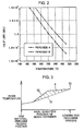
- a graph of FIG. 2 shows a relationship between the half-life of peroxide (i.e. reaction time of peroxide) and temperature.
- Peroxide A though having a half-life shorter than 10 seconds at 200°C, can react with a raw resin without any problem at a residence time and a mixed resin temperature in the conventional mixing extruder.
- product resin pellets can be adjusted to a required viscosity by use of the peroxide A in the conventional mixing extruder.
- peroxide being tested for new use in recent years has a long half-life, e.g. a half-life equal to or longer than 10 seconds at 200°C as shown in FIG. 2 .
- this is called peroxide B.
- Sufficient reaction of this peroxide B and the raw resin requires longer residence time and higher mixed resin temperature are required for as compared to the peroxide A.
- the use of peroxide B in the conventional mixing extruder as disclosed in patent literature 1 makes the residence time and the mixed resin temperature insufficient and makes the peroxide B and the raw resin not sufficiently react, thus causing the possibility of failing to adjust product resin pellets to a required viscosity.
- a residual volume of the peroxide in the product resin pellets is preferably equal to or less than 10 ppm from the standpoint of environment, the peroxide exceeding 10 ppm may remain.
- the residual volume of the peroxide in the product resin pellets discharged from the mixing extruder is merely referred to as a "residual volume of the peroxide".
- increasing the mixed resin temperature and the residence time enables more peroxide to react. Specifically, the greater the product of the mixed resin temperature and the residence time, the more peroxide reacts. Accordingly, as a method for increasing the mixed resin temperature, it can be considered to form the shape of mixing wings of a screw of the mixing extruder into shapes of strongly kneading or to increase the rotational speed of the screw.
- the "shapes of strongly kneading" include, for example, a shape having a small twist angle of the mixing wings and a large axial length, a shape in which the mixing wings are reversely twisted and a shape including kneading discs or mixing rotor segments.
- As a method for increasing the residence time it can be considered to make a barrel of the mixing extruder longer or increase the inner diameter of the barrel.
- the mixing wings of the screw having the shape of strongly kneading can produce a high mixed resin temperature.
- the mixed resin temperature is preferably lower from the standpoint of saving energy and granulation performance at a downstream side.
- just forming the mixing wings of the screw into shapes of strongly kneading is not enough to make it possible to adjust the mixed resin temperature according to the viscosity of the resin to be produced.
- An object of the present invention is to provide a method for adjusting the viscosity of a polypropylene, the method being capable of treating polypropylenes having various melt flow rates by use of peroxide and suppressing a residual volume of the peroxide, even if the peroxide has a half-life equal to or longer than 10 seconds at 200°C, while not involving considerable enlargement of a mixing extruder, and an mixing extruder suitable for this method.
- a first viscosity adjustment method provided by the present invention comprises: preparing of a mixing extruder including a barrel, a screw rotatably arranged in the barrel and having a plurality of mixing wings including a first mixing wing located at a most upstream side and a second mixing wing located downstream of the first mixing wing, peroxide feeder for feeding peroxide at a position upstream of the first mixing wing, a first flow path throttling mechanism capable of changing an area of a flow path for the polypropylene at a side downstream of the first mixing wing and upstream of the second mixing wing to thereby change a filling ratio of a polypropylene mixed by the first mixing wing, and a second flow path throttling mechanism capable of changing the area of a flow path for the polypropylene at the downstream side of the second mixing wing to thereby change a filling ratio of the polypropylene mixed by the second mixing wing; and mixing of the polypropylene and peroxide having a half-life equal to or
- a second viscosity adjustment method provided by the present invention comprises: preparing of a mixing extruder including a barrel, a screw rotatably arranged in the barrel and having a plurality of mixing wings including a first mixing wing located at a most upstream side and a second mixing wing located downstream of the first mixing wing, peroxide feeder for feeding peroxide at a position upstream of the first mixing wing, a first flow path throttling mechanism capable of changing an area of a flow path for the polypropylene at a side downstream of the first mixing wing and upstream of the second mixing wing to thereby change a filling ratio of a polypropylene mixed by the first mixing wing, a second flow path throttling mechanism capable of changing the area of the flow path for the polypropylene at the downstream side of the second mixing wing to thereby change a filling ratio of the polypropylene mixed by the second mixing wing; and mixing of the polypropylene and peroxide having a half-life equal to or longer than
- a mixing extruder comprises: a barrel; a screw rotatably arranged in the barrel and having a plurality of mixing wings including a first mixing wing located at a most upstream side and a second mixing wing located downstream of the first mixing wing, the first mixing wing being located upstream of a longitudinal central part of the screw in the barrel; peroxide feeder for feeding the peroxide at a position upstream of the first mixing wing; a first flow path throttling mechanism located downstream of the first mixing wing and upstream of the second mixing wing and adapted to throttle a flow path for the polypropylene to thereby change a filling ratio of the polypropylene mixed by the first mixing wing; and a second flow path throttling mechanism located downstream of the second mixing wing and adapted to throttle the flow path for the polypropylene to thereby change a filling ratio of the polypropylene mixed by the second mixing wing.
- a mixing extruder 1 is, as shown in FIG. 1 , a machine for mixing resin (polypropylene) and peroxide to adjusting the viscosity of the resin, that is, melting powder resin poured from a raw material feed hopper 11 and, at the same time, kneading the peroxide into the resin to bring them into a chemical reaction.
- This mixing extruder 1 can also constitute a mixing/granulating apparatus for manufacturing product resin pellets together with an unillustrated granulator.
- the mixing extruder 1 includes a barrel 10, the raw material feed hopper 11 attached to the barrel 10, peroxide feeder 12 attached to the barrel 10 or the raw material feed hopper 11, a pair of screws 20 arranged in the barrel 10, a gate device 31 (first flow path throttling mechanism) and a butterfly valve 36 (second flow path throttling mechanism) provided in the barrel 10.
- the barrel 10 is a tubular member inside which the screws 20 is arranged and has an upstream end portion and a downstream end portion.
- the barrel 10 is formed with a raw material feed opening 10a near the upstream end portion, through which opening a raw material is fed into the barrel 10.
- the barrel 10 is formed with a leading-end discharge opening 10b at the downstream end portion, through which opening the material, i.e. the mixed resin is discharged.
- the raw material feed hopper 11 is a device for introducing resin powder as a powder raw material, specifically, powder polypropylene, into the barrel 10.
- the raw material feed hopper 11 is connected to the raw material feed opening 10a of the barrel 10.
- the peroxide feeder 12 is a section for feeding peroxide B to the raw material.
- the peroxide feeder 12 is provided upstream of first mixing wings 21 to be described later.
- This peroxide feeder 12 may be attached to the raw material feed hopper 11 to feed the peroxide B into the raw material feed hopper 11 or may be attached to an upstream region of the barrel 10 to directly feed the peroxide B into the barrel 10.
- the peroxide feeder 12 only have to be capable of feeding a liquid peroxide or a powder peroxide to the raw material, constituted by, for example, a not shown nozzle or hopper.
- the peroxide B fed from the peroxide feeder 12 has a half-life equal to or longer than 10 seconds at 200°C. This half-life may be substantially just 10 seconds.
- FIG. 2 shows a relationship between the half-life of this peroxide B and temperature.
- the peroxide B has a shorter half-life at a higher temperature. That is, the higher the temperature, the higher a reaction rate.
- the screws 20 are arranged parallel to each other inside the barrel 10, while only a front screw 20 of them is shown in FIG. 1 .
- the mixing extruder according to the present invention may include a single screw or three or more screws.
- the respective screws 20 are arranged inside the barrel 10 and rotating about their respective center axes to thereby convey the resin, more specifically the material to be mixed including the polypropylene and the peroxide, from the raw material feed opening 10a at the upstream side to the leading-end discharge opening 10b at the downstream side by.
- a length L of the respective screws 20 in the barrel 10 is so set as to make L/D be equal to or larger than 30 (that is, L/D ⁇ 30) when D denotes the inner diameter of the barrel 10, i.e. the inner diameter of a circular hole housing the respective screws 20.
- the upper limit of the L/D is generally about 40 from the standpoint of torsionaln rigidity of screw shafts and manufacturing.
- the resin conveyed by the screws 20 is specifically the material to be mixed including the polypropylene and the peroxide.
- Each of the screws 20 includes the first mixing wing 21, a second mixing wing 22 and a feeding wing 23.
- a ratio Vm/V is called a filling ratio, which is a ratio of a volume Vm of the polypropylene to a volume V between the barrel 10 and the screw 20 in the mixing wings 21, 22 and the feeding wing 23.
- the respective mixing wings 21, 22 are sections for mixing and heating the polypropylene, provided at an upstream region and a downstream region of each screw 20, respectively.
- the mixing wings 21, 22 are specifically, for example, kneading discs or mixing rotor segments. If being too short, the mixing wings 21, 22 generate no mixing effect for the polypropylene.
- respective lengths M1, M2 of the mixing wings 21, 22 are so set as to satisfy M1/D ⁇ 1 and M2/D ⁇ 1 with respect to the inner diameter D of the barrel 10.
- the first mixing wing 21 is one that are arranged at a most upstream side of all the mixing wings, that is, the mixing wings 21, 22 in this embodiment, in each of the screws 20 to perform mixing at first.
- the first mixing wing 21 is located upstream of longitudinal central part 20c of each of the screws 20 in the barrel 10. In other words, the first mixing wing 21 is arranged in a length range of L/2 of each of the screws 20 at the upstream side.
- the first mixing wings 21 are preferably located at positions close to the upstream end portions of the screws 20, i.e. at positions close to the raw material feed opening 10a of the barrel 10. This enables the temperature of the polypropylene to be raised at a more upstream side, that is, enables a product of the temperature and a moving distance of the polypropylene (area S in FIG. 3 ) to be larger.
- the second mixing wings 22 is one provided downstream of each of the first mixing wing 21 and arranged at a most downstream side to perform mixing at last out of the mixing wings 21, 22, which are all the mixing wings in this embodiment.
- Each of the second mixing wing 22 is located downstream of the gate device 31 equivalent to the first flow path throttling mechanism and, in this embodiment, located downstream of the longitudinal central part 20c of each of the screws 20 in the barrel 10.
- the gate device 31 and the butterfly valve 36 are equivalent to the first and second flow path throttling mechanisms respectively and changes in their respective openings allow a passage area for the polypropylene in the barrel 10, i.e. an area of a material flow path when the gate device 31 and the butterfly valve 36 are viewed in a longitudinal direction of the screws 20 to be adjusted.
- a passage area for the polypropylene in the barrel 10 i.e. an area of a material flow path when the gate device 31 and the butterfly valve 36 are viewed in a longitudinal direction of the screws 20 to be adjusted.
- the filling ratios of the polypropylene mixed by the mixing wings located at the upstream sides of the gate device 31 and the butterfly valve 36 are increased, the temperature of the polypropylene rises and a residence time is extended.
- This mixing extruder further includes temperature sensors 32, 37 for detecting the temperature of the polypropylene.
- the temperature sensor 32 is disposed upstream of the gate device 31 and the temperature sensor 37 is disposed upstream of the butterfly valve 36.
- the respective openings of the gate device 31 and the butterfly valve 36 are adjusted according to the respective temperature of the polypropylene detected by the respective temperature sensors 32, 37.
- the gate device 31 as the first flow path throttling mechanism is able to increase and change the filling ratio of the polypropylene mixed by the first mixing wing 21 at the most upstream side. In other words, it is able to increase the filling ratio of the polypropylene at the upstream side of the longitudinal central part 20c of the screw 20 in the barrel 10.
- the opening of the gate device 31 can be narrowed so as to reduce the area of the polypropylene flow path to a lower limit area equal to or below 20 %, e.g. an area of 15 %, if the area when the gate device 31 is fully open is let 100 %.
- the opening of the gate device 31 is adjustable in a range from a specified lower limit opening equal to or below 20 % to 100 %.
- the gate device 31 is provided at a position downstream of the first mixing wings 21 as the mixing wings at the most upstream side and upstream of the second mixing wings 22, e.g. at a position downstream of and adjacent to the first mixing wings 21.
- the gate device 31 is provided near a longitudinal central part 10c of the barrel 10.
- the gate device 31 is formed of a pair of upper and lower plate-like members. These plate-like members are so arranged as to surround intermediate parts of the screws 20 having a circular cross section, i.e. parts provided with no mixing wings, from upper and lower sides, and as to simultaneously vertically move in opposite directions. Movements of these plate-like members change the opening of the gate device 31, i.e. changes the flow path area for the polypropylene at the gate device 31 in the mixing extruder 1.
- the butterfly valve 36 as the second flow path throttling mechanism is a valve adapted to operate so as to change the filling ratio of the polypropylene mixed by the second mixing wings located downstream of the gate device 31 and provided downstream of the second mixing wings 22.
- the butterfly valve 36 is arranged so as to make the second mixing wings 22 located between the gate device 31 and the butterfly valve 36 and, in this embodiment, arranged at a position downstream of the longitudinal central part 10c of the barrel 10, e.g. at a position near the leading-end discharge opening 10b and downstream of the screws 20.
- the butterfly valve 36 specifically includes a baffle rotatable about an axis perpendicular to a conveying direction of the polypropylene, and the rotation of this baffle changes the area of the polypropylene flow path in the mixing extruder 1. In short, the opening of the butterfly valve 36 is adjusted by the rotation of the baffle.
- the opening of the butterfly valve 36 is changed in the following cases.
- the opening of the butterfly valve 36 is changed when the temperature of the polypropylene mixed by the mixing wings at the most downstream, i.e. the second mixing wings 22 in this embodiment, is below a predetermined temperature (this is called "condition 1" below). Specifically, in the case of using peroxide having a half-life equal to or longer than 10 seconds at 200°C, the opening is changed so as to be narrowed when the temperature measured by the temperature sensor 37 is below 240°C.
- the position where the temperature is measured only has to be at the downstream side of the most downstream mixing wings, i.e. at the downstream side of the second mixing wings 22 in this embodiment; the position may be, for example, outside the leading-end discharge opening 10b.
- Throttling the butterfly valve 36 allows the temperature of the polypropylene mixed by the mixing wings 22 to reach a predetermined temperature (240°C). More specifically, the filling ratio of the polypropylene mixed by the mixing wings 22 located downstream of the gate device 31 (upstream of the butterfly valve 36) is increased, and the temperature of the polypropylene mixed by the second mixing wings 22 as the most downstream mixing wings in this embodiment becomes the predetermined temperature (240°C) or higher.
- the opening of the butterfly valve 36 is changed so as to be narrowed also when a melt flow rate of the raw material polypropylene (polypropylene fed to the raw material feed hopper 11 before mixing) is a predetermined value or higher (this is called “condition 2" below), specifically when the melt flow rate is 7 (g/10 minutes) or higher.
- condition 2 a melt flow rate of the raw material polypropylene
- the filling rate and temperature of the polypropylene mixed by the second mixing wings 22 located downstream of the gate device 31 and upstream of the butterfly valve 36 is thereby increased.
- the opening of the butterfly valve 36 may be narrowed when either one of the above “condition 1" and “condition 2" is satisfied or may be narrowed only when both “condition 1" and “condition 2" are satisfied.
- the length L of the screws 20, an adjustment range of the opening of the gate device 31 and that of the opening of the butterfly valve 36 are set so as to enable the total residence time of the polypropylene in the mixing extruder 1 to be adjusted to 15 seconds or longer.
- the total residence time of the polypropylene in the mixing extruder 1 can be extended by increasing the length L of the screws 20 or narrowing the opening of the gate device 31 or the butterfly valve 36.
- this mixing extruder 1 is an apparatus for adjusting the viscosity of the polypropylene by mixing the polypropylene and the peroxide, it can be also assumed that the mixing extruder 1 operates with no supply of peroxide.
- the mixed resin temperature i.e. the temperature of the polypropylene to be mixed is low from the standpoint of saving energy and granulation performance at the downstream side. Therefore, it is desirable that the mixing extruder 1 is able to not only adjust the mixed resin temperature according to the viscosity of the polypropylene as the raw material resin, but also adjust the mixed resin temperature responsively to the supply or no supply of the peroxide.
- the mixing extruder 1 increasing the openings of the gate device 31 and the butterfly valve 36 enables the mixing extruder 1 to prevent the mixed resin temperature from an excessive increase and be responsive to the case of no supply of peroxide. Furthermore, as described later, the mixing extruder 1 is not required to be longer and the inner diameter D of the barrel 10 is not required to be enlarged.
- Table 1 shows a residual volume of the peroxide B in product resin pellets after the experiment.
- “throttle 1 (intermediate)” indicates the gate device 31 as the first throttling mechanism and "throttle 2 (leading end)” indicates the butterfly valve 36 as the second throttling mechanism.
- the melt flow rate of the raw material resin can be measured based on a measurement method specified by JIS K7210 by use of a tester equivalent to the one specified by JIS K6760; however, in this Example, a value published by a material manufacturer is used as the melt flow rate of the raw material resin.
- the peroxide residual volume is preferably 10 ppm or less
- the peroxide residual volume in Example 1 was suppressed to an amount sufficiently less than 10 ppm (0.3 ppm or less).
- a discharged resin temperature i.e. the temperature of the polypropylene mixed by the second mixing wings 22 as the most downstream mixing wings and located near the leading-end discharge opening 10b was 247°C higher than 240°C.
- Table 2 shows the residual volumes of the peroxide B in product resin pellets after the experiments. As shown in this Table 2, the peroxide residual volume was 10 ppm or more and the discharged resin temperature was 229°C lower than 240°C according to Examples 2 and 3.
- the mixing extruder including only the gate device 31 is capable of making the mixed resin temperature be an appropriate temperature when the raw material resin has a high viscosity as in Example 1, but is not capable of raising the mixed resin temperature to an appropriate temperature, i.e. a high temperature enough to allow the peroxide B to sufficiently react so as to reduce the residual volume of the peroxide B to below 10 ppm, when the raw material resin has a low viscosity as in Examples 2 and 3.
- the mixing extruder including only the butterfly valve 36 is not capable of increase the mixed resin temperature enough to allow the peroxide B to sufficiently react, because a product of the moving distance and temperature of the polypropylene (area S in FIG. 3 to be described later) therein is small as compared with the case where only the gate device 31 is included.
- the peroxide residual volume was suppressed to amounts (0.69 ppm and 0.3 ppm) sufficiently less than 10 ppm by narrowing the opening of the butterfly valve 36 in addition to that of the gate device 31, and the discharged resin temperature was 240°C or higher, specifically 240°C in Example 4 and 246°C in Example 5.
- the mixing extruder 1 and the method for adjusting the viscosity of a polypropylene by use of the mixing extruder 1 according to this embodiment have the following features.
- the filling ratio of the polypropylene mixed by the first mixing wings 21 at the most upstream side is increased by the gate device 31, whereby the temperature of the polypropylene mixed by the first mixing wings 21 at the most upstream side is increased as compared with the case where this filling ratio is not increased.
- the butterfly valve 36 is capable of changing the filling ratio of the polypropylene mixed by the second mixing wings 22 downstream of the gate device 31, thereby increasing the temperature of the polypropylene mixed by the second mixing wings 22 located downstream of the gate device 31 as compared with the case where this filling ratio is not increased.
- This largely contributes to the effects of the present invention. Specifically, in the case where the peroxide B (see FIG.2 ) having a half-life equal to or longer than 10 seconds at 200°C is used and the temperature of the polypropylene mixed by the mixing wings at the most downstream side, i.e.
- the second mixing wings 22 in this embodiment is below the predetermined temperature (240°C), just increasing the filling ratio of the polypropylene only by the gate device 31 is not enough to prevent the residual volume of the peroxide B in the polypropylene discharged from the mixing extruder from becoming larger than the predetermined value (10 ppm); however, in such a case, increasing the filling ratio of the polypropylene by the butterfly valve 36 enables the temperature of the polypropylene mixed by the second mixing wings 22 as the mixing wings at the most downstream side to be increased to or above the predetermined temperature (240°C). This allows the polypropylene and the peroxide B to react more and the residual volume of the peroxide B having a half-life equal to or longer than 10 seconds at 200°C to be suppressed to or below the predetermined value (10 ppm).
- the viscosity adjustment method in this mixing extruder 1 in the case that the temperature of the polypropylene mixed by the second mixing wings 22 at the most downstream side is equal to or above the predetermined temperature (240°C), what is required is only to increase the filling ratio and the temperature of the polypropylene by the gate device 31 and it is not required to increase the filling ratio and temperature by the butterfly valve 36; therefore this case allows the butterfly valve 36 to be, for example, fully opened.
- the viscosity adjustment method in this mixing extruder 1 can deal with treatments of polypropylenes having various melt flow rates.
- the viscosity adjustment method in this mixing extruder not requiring an increase in the length of the mixing extruder 1 (lengths of the barrel 10 and the screws 20) and the inner diameter D of the barrel 10, enables the residual volume of the peroxide B to be suppressed as described involving no considerable enlargement of the mixing extruder 1.
- the viscosity adjustment method in this mixing extruder 1 in the case that the melt flow rate of the polypropylene as the raw material is below 7 (g/10 minutes), what is required is only to increase the filling ratio and the temperature of the polypropylene by the gate device 31 and it is not required to increase the filling ratio and temperature by the butterfly valve 36; therefore this case allows the butterfly valve 36 to be, for example, fully opened.
- the viscosity adjustment method in this mixing extruder 1 can deal with treatments of polypropylenes having various melt flow rates.
- FIG. 3 shows a relationship between axial-direction position of the mixing extruder 1 shown in FIG. 1 and the temperature of the resin, i.e. the polypropylene.
- FIG. 3 has a broken line T1 which indicates a resin temperature distribution when the gate device 31 and the butterfly valve 36 are not present or the flow path is not throttled and a solid line T2 which indicates a resin temperature distribution when the flow path is throttled by the gate device 31 and the butterfly valve 36.
- the product of the moving distance and temperature of the polypropylene is larger by an area S than that in the case of no throttling the flow path; therefore, if the moving speed of the polypropylene is constant, the residence time becomes longer as the moving distance becomes longer. Accordingly, the larger the area S, the more the reaction of the peroxide B.
- the area S is increased as the position where the temperature of the polypropylene is more upstream, i.e. closer to the raw material feed opening 10a.
- the first mixing wings 21 at the most upstream side of the mixing extruder 1, being provided upstream of the longitudinal central parts 20c of the screws 20 in the barrel 10, increases the temperature of the polypropylene by the first mixing wings 21 earlier to extend the residence time of the polypropylene in the mixing extruder 1 in this state, as described in (Feature 3), thereby further suppressing the residual volume of the peroxide B.
- the butterfly valve 36 can increase the filling ratio and temperature of the polypropylene mixed by the second mixing wings 22 located downstream of the gate device 31, even in the case of treating a polypropylene having a melt flow rate at which the residual volume of the peroxide B cannot be suppressed to or below the predetermined value (10 ppm) only by the gate device 31, the residual volume of the peroxide B can be more suppressed by increasing the filling ratio and temperature of the polypropylene by the butterfly valve 36.
- the butterfly valve 36 may be, for example, fully opened.
- treatments of polypropylenes having various melt flow rates can be performed by only the single mixing extruder 1.
- the gate device 31 of this mixing extruder 1 is able to narrow the opening of the flow path for the polypropylene to 20 % or below of the opening when the gate device 31 is fully open. This expands adjustable ranges of the filling ratio and temperature of the polypropylene mixed by the first mixing wings 21 at the most upstream side, thus expanding a range of the melt flow rate of mixable polypropylenes.
- setting the length L of the screws 20 arranged in the barrel 10 having the inner diameter D so as to satisfy L/D ⁇ 30 makes it possible to obtain an sufficiently long total residence time of the polypropylene in the mixing extruder 1 as compared with the case where L/D is below 30. This allows even peroxide B having a long half-life to react with the polypropylene. Accordingly, combination of setting L/D as described above and the flow path throttling mechanisms (gate device 31, butterfly valve 36) makes it possible to provide a mixing extruder capable of effectively suppressing a residual volume of even peroxide having a long half-life.
- the length L of the screws 20, the adjustment range for the opening of the gate device 31 and that for the opening of the butterfly valve 36 are so set that the total residence time of the polypropylene in the mixing extruder 1 is adjustable to 15 seconds or longer. This enables a sufficiently long total residence time to be set, thus making it possible to effectively suppress the residual volume of even the peroxide B having a long half-life.
- FIG. 4 shows a mixing extruder 101 according to a second embodiment of the present invention.
- This mixing extruder 101 includes a gate device 136 shown in FIG. 4 as a second throttling mechanism instead of the butterfly valve 36 shown in FIG. 1 .
- the gate device 136 is opened and closed on the same conditions as the above butterfly valve 36.
- the gate device 136 includes a pair of upper and lower plate-like members similar to the gate device 31, these plate-like members being arranged so as to surround intermediate parts of screws 20 having a circular cross section from upper and lower sides, for example, near a leading-end discharge opening 10b of a barrel 10.
- the gate device 136 only has to be located at a downstream side of second mixing wings 22 located downstream of the gate device 31 and is arranged, for example, adjacent to the mixing wings 22.
- each screw may include three or more mixing wings. While, in the first and second embodiments, the second mixing wings in relation to which the filling ratio of the polypropylene can be changed by the second flow path throttling mechanism, i.e. by the butterfly valve 36 shown in FIG. 1 or the gate device 136 shown in FIG. 4 and which are located downstream of the gate device 31 as the first flow path throttling mechanism corresponds to the mixing wings at the most downstream side, in the case of the screws 20 each including three or more mixing wings, the "mixing wings located immediately downstream of the first flow path throttling mechanism" and the "mixing wings at the most downstream side” may differ. For example, there may be provided additional mixing wings other than the second mixing wings between the gate device 31 shown in FIGS. 1 and 4 and the second mixing wings 22. Besides, there may be provided "mixing wings at the most downstream side" other than the second mixing wings 22, for example, downstream of the gate device 136 shown in FIG. 4 .
- the conditions for operating the second flow path throttling mechanism according to the present invention e.g. the butterfly valve 36 shown in FIG. 1 or the gate device 136 shown in FIG. 4 can be arbitrarily set.
- a specific value of the temperature or melt flow rate as a basis for judgment as to whether or not the flow path should be throttled can be arbitrarily changed according to a targeted residual volume (e.g. 10 ppm or less) of the peroxide.
- the present invention provides: a method for adjusting the viscosity of a polypropylene which method is capable of treating polypropylenes having various melt flow rate by use of peroxide without considerably enlarging the mixing extruder and suppressing the residual volume of the peroxide even if the peroxide has a half-life equal to or longer than 10 seconds at 200°C; and a mixing extruder suitable for the method.
- the present invention provides a first viscosity adjustment method, which includes: preparing a mixing extruder including a barrel, a screw rotatably arranged in the barrel and having a plurality of mixing wings including a first mixing wing located at a most upstream side and a second mixing wing located downstream of the first mixing wing, peroxide feeder for feeding peroxide at a position upstream of the first mixing wing, a first flow path throttling mechanism capable of changing an area of a flow path for the polypropylene at a side downstream of the first mixing wing and upstream of the second mixing wing to thereby change a filling ratio of a polypropylene mixed by the first mixing wing, and a second flow path throttling mechanism capable of changing the area of the flow path for the polypropylene at the downstream side of the second mixing wing to thereby change a filling ratio of the polypropylene mixed by the second mixing wing; and mixing of the polypropylene and peroxide having a half-life equal to or
- the viscosity adjustment method in the mixing extruder includes increasing the filling ratio of the polypropylene mixed by the first mixing wing at the most upstream side by the first flow path throttling mechanism, for mixing the polypropylene and the peroxide, thereby enabling the temperature of the polypropylene mixed by the first mixing wing to be higher than the case where this filling ratio is not increased.
- the second flow path throttling mechanism is able to change the filling ratio of the polypropylene mixed by the second mixing wing located downstream of the first flow path throttling mechanism, thereby enabling the temperature of the polypropylene mixed by the mixing wing located downstream of the first flow path throttling mechanism to be higher than the case where this filling ratio is not increased. This largely contributes to the accomplishment of the object of the present invention.
- this first viscosity adjustment method when the temperature of the polypropylene mixed by the mixing wing at the most downstream side is equal to or above the predetermined temperature, only the first flow path throttling mechanism has to increase the filling ratio and temperature of the polypropylene while the second flow path throttling mechanism does not have to.
- the viscosity adjustment method in this mixing extruder can deal with treatments of polypropylenes having various melt flow rates.
- the viscosity adjustment method in this mixing extruder has no requirement of increasing either the length of the mixing extruder or the inner diameter of the barrel, thus making it possible to suppress the residual volume of the peroxide not involving a considerable enlargement of the mixing extruder.
- the present invention provides a second viscosity adjustment method which includes: preparing a mixing extruder including a barrel, a screw rotatably arranged in the barrel and having a plurality of mixing wings including a first mixing wing located at a most upstream side and a second mixing wing located downstream of the first mixing wing, peroxide feeder for feeding peroxide at a position upstream of the first mixing wing, a first flow path throttling mechanism capable of changing an area of a flow path for the polypropylene at a side downstream of the first mixing wing and upstream of the second mixing wing to thereby change a filling ratio of a polypropylene mixed by the first mixing wing, a second flow path throttling mechanism capable of changing the area of the flow path for the polypropylene at the downstream side of the second mixing wing to thereby change a filling ratio of the polypropylene mixed by the second mixing wing by; and mixing of the polypropylene and peroxide having a half-life equal to or longer
- the first flow path throttling mechanism is able to increase the filling ratio and temperature of the polypropylene mixed by the first mixing wing at the most upstream side and the second flow path throttling mechanism is able to increase the filling ratio and temperature of the polypropylene mixed by the second mixing wing located downstream of the first flow path throttling mechanism. This largely contributes to the accomplishment of the object of the present invention.
- this second viscosity adjustment method when the melt flow rate of the polypropylene as the raw material is below 7 (g/10 minutes), only the first flow path throttling mechanism has to increase the filling ratio and temperature of the polypropylene while the second flow path throttling mechanism does not have to.
- the viscosity adjustment method in this mixing extruder can deal with treatments of polypropylenes having various melt flow rates.
- this second viscosity adjustment method does not require considerable enlargement of the mixing extruder similar to the first method.
- the polypropylene having the thus increased filling ratio is mixed by the first mixing wing.
- This enables the temperature of the polypropylene to be earlier increased at a more upstream side than the case where the filling ratio of the polypropylene is increased only at the downstream side of the longitudinal central part of the screw, thus making it possible to extend a residence time of the polypropylene having the thus increased temperature in the mixing extruder, that is, making it possible to increase a product of the temperature and residence time of the polypropylene.
- the polypropylene and the peroxide is therefore allowed to react more, resulting in further suppressing the residual volume of the peroxide.
- the present invention also provides a mixing extruder for adjusting the viscosity of a polypropylene by mixing the polypropylene and peroxide.
- This mixing extruder comprises: a barrel; a screw rotatably arranged in the barrel and having a plurality of screws including a first mixing wing located at a most upstream side and a second mixing wing located downstream of the first mixing wing, the first mixing wing being located upstream of a longitudinal central part of the screw in the barrel; peroxide feeder for feeding the peroxide at a position upstream of the first mixing wing; a first flow path throttling mechanism located downstream of the first mixing wing and upstream of the second mixing wing and adapted to throttle a flow path for the polypropylene to thereby change a filling ratio of the polypropylene mixed by the first mixing wing; and a second flow path throttling mechanism located downstream of the second mixing wing and adapted to throttle the flow path for the polypropylene to thereby change a filling ratio
- the first flow path throttling mechanism of this mixing extruder is able to increase the filling ratio and temperature of the polypropylene mixed by the first mixing wing at the most upstream side.
- the first mixing wing being provided upstream of the longitudinal central part of the screw in the barrel, is able to raise the temperature of the polypropylene earlier to extend a residence time of the polypropylene in the mixing extruder in this state, thereby suppressing the residual volume of the peroxide.
- the second flow path throttling mechanism is able to increase the filling ratio and temperature of the polypropylene mixed by the second mixing wing located downstream of the first flow path throttling mechanism. Accordingly, even in the case of treating a polypropylene having a melt flow rate at which the residual volume of peroxide cannot be suppressed to or below a predetermined value only by the first flow path throttling mechanism, the residual volume of the peroxide can be suppressed by increasing the filling ratio and temperature of the polypropylene by the second flow path throttling mechanism.
- the opening of the second flow path throttling mechanism can be preferably increased to reduce flow path resistance.
- the first flow path throttling mechanism is adapted to narrow an area of the flow path for the polypropylene so as to reduce the area to or below 20 % of the area when the first flow path throttling mechanism is fully opened.
- the first flow path throttling mechanism having such a large area changing range is able to change the filling ratio and temperature of the polypropylene mixed by the first mixing wing at the most upstream side in large ranges, thus allowing a melt flow rate range of polypropylenes which can be dealt with (can be mixed) to be widened.
- the screw arranged in the barrel has a length L satisfying L/D ⁇ 30 when D denotes the inner diameter of the barrel.
- the mixing extruder comprising the screw having such a length L sufficiently extends a total residence time of the polypropylene in the mixing extruder, thus allowing even peroxide having a long half-time to react more with the polypropylene.
- the combination of the first and second flow path throttling mechanisms of the mixing extruder enables a mixing state of the mixing extruder to be adjusted so as to reduce a residual volume of even peroxide having a long half-life.
- the length of the screw, an adjustment range for the opening of the first throttling mechanism and an adjustment range for the opening of the second throttling mechanism are preferably so set that the total residence time of the polypropylene in the mixing extruder is adjustable to 15 seconds or longer.
- This mixing extruder can sufficiently extend the total residence time of the polypropylene in the mixing extruder and effectively suppress the residual volume of even peroxide having a long half-life.
Landscapes
- Engineering & Computer Science (AREA)
- Mechanical Engineering (AREA)
- Processing And Handling Of Plastics And Other Materials For Molding In General (AREA)
- Extrusion Moulding Of Plastics Or The Like (AREA)
Abstract
Description
- The present invention relates to a method for adjusting the viscosity of a polypropylene using a mixing extruder for resin, and a mixing extruder for resin.
- Conventionally, there has been a mixing extruder for melting raw resin (resin powder) such as polypropylene and mixing it with various additives. This mixing extruder is used for a production method called vis-braking or cracking. Specifically, raw resin is fed from a raw material feeder (raw material feed hopper) to the mixing extruder and peroxide is also fed to the mixing extruder simultaneously with the feed of the raw resin. The fed raw resin and peroxide are mixed in the mixing extruder to react with each other at a high temperature. This reaction cuts intermolecular main chains of the raw resin to reduce the molecular weight of the raw resin. The viscosity and melt flow rate of resin pellets as a product are thereby adjusted. Such a mixing extruder is disclosed, for example, in patent literature 1.
- Sufficient reaction between the peroxide and the raw resin require specified residence time and mixed resin temperature. Necessary residence time and mixed resin temperature differ depending on the type of the peroxide. The residence time means a residence time of a mixture of the peroxide and the raw resin in the mixing extruder, i.e. a mixing time. The mixed resin temperature means the temperature of the raw resin and the peroxide in the mixing extruder, i.e. an ambient temperature or an operating resin temperature.
- A graph of
FIG. 2 shows a relationship between the half-life of peroxide (i.e. reaction time of peroxide) and temperature. Peroxide A, though having a half-life shorter than 10 seconds at 200°C, can react with a raw resin without any problem at a residence time and a mixed resin temperature in the conventional mixing extruder. Thus, product resin pellets can be adjusted to a required viscosity by use of the peroxide A in the conventional mixing extruder. - However, peroxide being tested for new use in recent years has a long half-life, e.g. a half-life equal to or longer than 10 seconds at 200°C as shown in
FIG. 2 . Hereinafter, this is called peroxide B. Sufficient reaction of this peroxide B and the raw resin requires longer residence time and higher mixed resin temperature are required for as compared to the peroxide A. Thus, the use of peroxide B in the conventional mixing extruder as disclosed in patent literature 1 makes the residence time and the mixed resin temperature insufficient and makes the peroxide B and the raw resin not sufficiently react, thus causing the possibility of failing to adjust product resin pellets to a required viscosity. Furthermore, although a residual volume of the peroxide in the product resin pellets is preferably equal to or less than 10 ppm from the standpoint of environment, the peroxide exceeding 10 ppm may remain. Hereinafter, the residual volume of the peroxide in the product resin pellets discharged from the mixing extruder is merely referred to as a "residual volume of the peroxide". - According to the graph shown in
FIG. 2 , increasing the mixed resin temperature and the residence time enables more peroxide to react. Specifically, the greater the product of the mixed resin temperature and the residence time, the more peroxide reacts. Accordingly, as a method for increasing the mixed resin temperature, it can be considered to form the shape of mixing wings of a screw of the mixing extruder into shapes of strongly kneading or to increase the rotational speed of the screw. The "shapes of strongly kneading" include, for example, a shape having a small twist angle of the mixing wings and a large axial length, a shape in which the mixing wings are reversely twisted and a shape including kneading discs or mixing rotor segments. As a method for increasing the residence time, it can be considered to make a barrel of the mixing extruder longer or increase the inner diameter of the barrel. - The mixing wings of the screw having the shape of strongly kneading can produce a high mixed resin temperature. On the other hand, in the case of adjusting the viscosity of a high-viscosity resin, the mixed resin temperature is preferably lower from the standpoint of saving energy and granulation performance at a downstream side. However, just forming the mixing wings of the screw into shapes of strongly kneading is not enough to make it possible to adjust the mixed resin temperature according to the viscosity of the resin to be produced.
- Increase in the rotational speed of the screw increases the mixed resin temperature. However, a range of the mixed resin temperature adjustable by the screw rotational speed is not sufficient. Hence, it is impossible to set the mixed resin temperature to a temperature which is a relatively low temperature appropriate at the time of producing a high-viscosity resin and a relatively high temperature necessary for sufficient reaction of the peroxide B when the peroxide B described above is used.
- Making the mixing extruder longer or increasing the inner diameter of the barrel extends he residence time. However, this excessively increases cost in the case of producing a high-viscosity resin. Furthermore, an excessively long residence time may excessively increase the mixed resin temperature.
-
- [Patent literature 1] Japanese Unexamined Patent Publication No.
H08-276422 - An object of the present invention is to provide a method for adjusting the viscosity of a polypropylene, the method being capable of treating polypropylenes having various melt flow rates by use of peroxide and suppressing a residual volume of the peroxide, even if the peroxide has a half-life equal to or longer than 10 seconds at 200°C, while not involving considerable enlargement of a mixing extruder, and an mixing extruder suitable for this method.
- A first viscosity adjustment method provided by the present invention comprises: preparing of a mixing extruder including a barrel, a screw rotatably arranged in the barrel and having a plurality of mixing wings including a first mixing wing located at a most upstream side and a second mixing wing located downstream of the first mixing wing, peroxide feeder for feeding peroxide at a position upstream of the first mixing wing, a first flow path throttling mechanism capable of changing an area of a flow path for the polypropylene at a side downstream of the first mixing wing and upstream of the second mixing wing to thereby change a filling ratio of a polypropylene mixed by the first mixing wing, and a second flow path throttling mechanism capable of changing the area of a flow path for the polypropylene at the downstream side of the second mixing wing to thereby change a filling ratio of the polypropylene mixed by the second mixing wing; and mixing of the polypropylene and peroxide having a half-life equal to or longer than 10 seconds at 200°C using this mixing extruder, wherein, in the mixing, the flow path for the polypropylene located downstream of the first mixing wing is throttled by the first flow path throttling mechanism to thereby increase the filling ratio of the polypropylene at the first mixing wing; and, when the temperature of the polypropylene mixed by the most downstream one of the mixing wings is below a predetermined temperature, the flow path for the polypropylene located downstream of the second mixing wing is throttled by the second flow path throttling mechanism to increase the filling ratio of the polypropylene at the second mixing wing, thereby bringing the polypropylene mixed by the mixing wing at the most downstream side to or above the predetermined temperature.
- A second viscosity adjustment method provided by the present invention comprises: preparing of a mixing extruder including a barrel, a screw rotatably arranged in the barrel and having a plurality of mixing wings including a first mixing wing located at a most upstream side and a second mixing wing located downstream of the first mixing wing, peroxide feeder for feeding peroxide at a position upstream of the first mixing wing, a first flow path throttling mechanism capable of changing an area of a flow path for the polypropylene at a side downstream of the first mixing wing and upstream of the second mixing wing to thereby change a filling ratio of a polypropylene mixed by the first mixing wing, a second flow path throttling mechanism capable of changing the area of the flow path for the polypropylene at the downstream side of the second mixing wing to thereby change a filling ratio of the polypropylene mixed by the second mixing wing; and mixing of the polypropylene and peroxide having a half-life equal to or longer than 10 seconds at 200°C using this mixing extruder, wherein, in the mixing, the flow path for the polypropylene located downstream of the first mixing wing is throttled by the first flow path throttling mechanism to increase the filling ratio of the polypropylene at the first mixing wing; and, when a melt flow rate of the polypropylene as a raw material is 7 (g/10 minutes) or higher, the flow path for the polypropylene located downstream of the second mixing wing is throttled by the second flow path throttling mechanism to increase the filling ratio of the polypropylene at the second mixing wing.
- A mixing extruder provided by the present invention comprises: a barrel; a screw rotatably arranged in the barrel and having a plurality of mixing wings including a first mixing wing located at a most upstream side and a second mixing wing located downstream of the first mixing wing, the first mixing wing being located upstream of a longitudinal central part of the screw in the barrel; peroxide feeder for feeding the peroxide at a position upstream of the first mixing wing; a first flow path throttling mechanism located downstream of the first mixing wing and upstream of the second mixing wing and adapted to throttle a flow path for the polypropylene to thereby change a filling ratio of the polypropylene mixed by the first mixing wing; and a second flow path throttling mechanism located downstream of the second mixing wing and adapted to throttle the flow path for the polypropylene to thereby change a filling ratio of the polypropylene mixed by the second mixing wing.
-
-
FIG. 1 is a front view in section of a mixing extruder according to a first embodiment of the invention, -
FIG. 2 is a graph showing a relationship between half-time of peroxide and temperature, -
FIG. 3 is a graph diagrammatically showing a temperature distribution of a polypropylene in the mixing extruder, and -
FIG. 4 is a front view in section of a mixing extruder according to a second embodiment of the invention. - There will be described a mixing extruder and a viscosity adjustment method in the mixing extruder according to a first embodiment of the present invention below with reference to
FIGS. 1 to 3 . - A mixing extruder 1 according to this embodiment is, as shown in
FIG. 1 , a machine for mixing resin (polypropylene) and peroxide to adjusting the viscosity of the resin, that is, melting powder resin poured from a rawmaterial feed hopper 11 and, at the same time, kneading the peroxide into the resin to bring them into a chemical reaction. This mixing extruder 1 can also constitute a mixing/granulating apparatus for manufacturing product resin pellets together with an unillustrated granulator. - The mixing extruder 1 includes a
barrel 10, the rawmaterial feed hopper 11 attached to thebarrel 10,peroxide feeder 12 attached to thebarrel 10 or the rawmaterial feed hopper 11, a pair ofscrews 20 arranged in thebarrel 10, a gate device 31 (first flow path throttling mechanism) and a butterfly valve 36 (second flow path throttling mechanism) provided in thebarrel 10. - The
barrel 10 is a tubular member inside which thescrews 20 is arranged and has an upstream end portion and a downstream end portion. Thebarrel 10 is formed with a raw material feed opening 10a near the upstream end portion, through which opening a raw material is fed into thebarrel 10. Thebarrel 10 is formed with a leading-end discharge opening 10b at the downstream end portion, through which opening the material, i.e. the mixed resin is discharged. - The raw
material feed hopper 11 is a device for introducing resin powder as a powder raw material, specifically, powder polypropylene, into thebarrel 10. The rawmaterial feed hopper 11 is connected to the raw material feed opening 10a of thebarrel 10. - The
peroxide feeder 12 is a section for feeding peroxide B to the raw material. Theperoxide feeder 12 is provided upstream offirst mixing wings 21 to be described later. Thisperoxide feeder 12 may be attached to the rawmaterial feed hopper 11 to feed the peroxide B into the rawmaterial feed hopper 11 or may be attached to an upstream region of thebarrel 10 to directly feed the peroxide B into thebarrel 10. Theperoxide feeder 12 only have to be capable of feeding a liquid peroxide or a powder peroxide to the raw material, constituted by, for example, a not shown nozzle or hopper. - The peroxide B fed from the
peroxide feeder 12 has a half-life equal to or longer than 10 seconds at 200°C. This half-life may be substantially just 10 seconds.FIG. 2 shows a relationship between the half-life of this peroxide B and temperature. The peroxide B has a shorter half-life at a higher temperature. That is, the higher the temperature, the higher a reaction rate. - The
screws 20 are arranged parallel to each other inside thebarrel 10, while only afront screw 20 of them is shown inFIG. 1 . The mixing extruder according to the present invention may include a single screw or three or more screws. - As shown in
FIG. 1 , therespective screws 20 are arranged inside thebarrel 10 and rotating about their respective center axes to thereby convey the resin, more specifically the material to be mixed including the polypropylene and the peroxide, from the rawmaterial feed opening 10a at the upstream side to the leading-end discharge opening 10b at the downstream side by. A length L of therespective screws 20 in thebarrel 10 is so set as to make L/D be equal to or larger than 30 (that is, L/D ≥ 30) when D denotes the inner diameter of thebarrel 10, i.e. the inner diameter of a circular hole housing the respective screws 20. The upper limit of the L/D is generally about 40 from the standpoint of torsionaln rigidity of screw shafts and manufacturing. - The resin conveyed by the
screws 20 is specifically the material to be mixed including the polypropylene and the peroxide. - Each of the
screws 20 includes the first mixingwing 21, asecond mixing wing 22 and a feedingwing 23. In this specification, a ratio Vm/V is called a filling ratio, which is a ratio of a volume Vm of the polypropylene to a volume V between thebarrel 10 and thescrew 20 in the mixingwings wing 23. - The
respective mixing wings screw 20, respectively. The mixingwings wings wings barrel 10. - The
first mixing wing 21 is one that are arranged at a most upstream side of all the mixing wings, that is, the mixingwings screws 20 to perform mixing at first. Thefirst mixing wing 21 is located upstream of longitudinalcentral part 20c of each of thescrews 20 in thebarrel 10. In other words, the first mixingwing 21 is arranged in a length range of L/2 of each of thescrews 20 at the upstream side. Thefirst mixing wings 21 are preferably located at positions close to the upstream end portions of thescrews 20, i.e. at positions close to the rawmaterial feed opening 10a of thebarrel 10. This enables the temperature of the polypropylene to be raised at a more upstream side, that is, enables a product of the temperature and a moving distance of the polypropylene (area S inFIG. 3 ) to be larger. - The
second mixing wings 22 is one provided downstream of each of the first mixingwing 21 and arranged at a most downstream side to perform mixing at last out of the mixingwings wing 22 is located downstream of thegate device 31 equivalent to the first flow path throttling mechanism and, in this embodiment, located downstream of the longitudinalcentral part 20c of each of thescrews 20 in thebarrel 10. - The
gate device 31 and thebutterfly valve 36 are equivalent to the first and second flow path throttling mechanisms respectively and changes in their respective openings allow a passage area for the polypropylene in thebarrel 10, i.e. an area of a material flow path when thegate device 31 and thebutterfly valve 36 are viewed in a longitudinal direction of thescrews 20 to be adjusted. As the area of the material flow path is reduced by narrowing the openings of thegate device 31 and thebutterfly valve 36, the filling ratios of the polypropylene mixed by the mixing wings located at the upstream sides of thegate device 31 and thebutterfly valve 36 are increased, the temperature of the polypropylene rises and a residence time is extended. - This mixing extruder further includes
temperature sensors temperature sensor 32 is disposed upstream of thegate device 31 and thetemperature sensor 37 is disposed upstream of thebutterfly valve 36. The respective openings of thegate device 31 and thebutterfly valve 36 are adjusted according to the respective temperature of the polypropylene detected by therespective temperature sensors - The
gate device 31 as the first flow path throttling mechanism is able to increase and change the filling ratio of the polypropylene mixed by the first mixingwing 21 at the most upstream side. In other words, it is able to increase the filling ratio of the polypropylene at the upstream side of the longitudinalcentral part 20c of thescrew 20 in thebarrel 10. The opening of thegate device 31 can be narrowed so as to reduce the area of the polypropylene flow path to a lower limit area equal to or below 20 %, e.g. an area of 15 %, if the area when thegate device 31 is fully open is let 100 %. In short, the opening of thegate device 31 is adjustable in a range from a specified lower limit opening equal to or below 20 % to 100 %. - The
gate device 31 is provided at a position downstream of thefirst mixing wings 21 as the mixing wings at the most upstream side and upstream of thesecond mixing wings 22, e.g. at a position downstream of and adjacent to thefirst mixing wings 21. In this embodiment, thegate device 31 is provided near a longitudinalcentral part 10c of thebarrel 10. - Specifically, the
gate device 31 is formed of a pair of upper and lower plate-like members. These plate-like members are so arranged as to surround intermediate parts of thescrews 20 having a circular cross section, i.e. parts provided with no mixing wings, from upper and lower sides, and as to simultaneously vertically move in opposite directions. Movements of these plate-like members change the opening of thegate device 31, i.e. changes the flow path area for the polypropylene at thegate device 31 in the mixing extruder 1. - The
butterfly valve 36 as the second flow path throttling mechanism is a valve adapted to operate so as to change the filling ratio of the polypropylene mixed by the second mixing wings located downstream of thegate device 31 and provided downstream of thesecond mixing wings 22. In other words, thebutterfly valve 36 is arranged so as to make thesecond mixing wings 22 located between thegate device 31 and thebutterfly valve 36 and, in this embodiment, arranged at a position downstream of the longitudinalcentral part 10c of thebarrel 10, e.g. at a position near the leading-end discharge opening 10b and downstream of thescrews 20. Thebutterfly valve 36 specifically includes a baffle rotatable about an axis perpendicular to a conveying direction of the polypropylene, and the rotation of this baffle changes the area of the polypropylene flow path in the mixing extruder 1. In short, the opening of thebutterfly valve 36 is adjusted by the rotation of the baffle. - The opening of the
butterfly valve 36 is changed in the following cases. - The opening of the
butterfly valve 36 is changed when the temperature of the polypropylene mixed by the mixing wings at the most downstream, i.e. thesecond mixing wings 22 in this embodiment, is below a predetermined temperature (this is called "condition 1" below). Specifically, in the case of using peroxide having a half-life equal to or longer than 10 seconds at 200°C, the opening is changed so as to be narrowed when the temperature measured by thetemperature sensor 37 is below 240°C. The position where the temperature is measured only has to be at the downstream side of the most downstream mixing wings, i.e. at the downstream side of thesecond mixing wings 22 in this embodiment; the position may be, for example, outside the leading-end discharge opening 10b. Throttling thebutterfly valve 36 allows the temperature of the polypropylene mixed by the mixingwings 22 to reach a predetermined temperature (240°C). More specifically, the filling ratio of the polypropylene mixed by the mixingwings 22 located downstream of the gate device 31 (upstream of the butterfly valve 36) is increased, and the temperature of the polypropylene mixed by thesecond mixing wings 22 as the most downstream mixing wings in this embodiment becomes the predetermined temperature (240°C) or higher. - The opening of the
butterfly valve 36 is changed so as to be narrowed also when a melt flow rate of the raw material polypropylene (polypropylene fed to the rawmaterial feed hopper 11 before mixing) is a predetermined value or higher (this is called "condition 2" below), specifically when the melt flow rate is 7 (g/10 minutes) or higher. The filling rate and temperature of the polypropylene mixed by thesecond mixing wings 22 located downstream of thegate device 31 and upstream of thebutterfly valve 36 is thereby increased. - The opening of the
butterfly valve 36 may be narrowed when either one of the above "condition 1" and "condition 2" is satisfied or may be narrowed only when both "condition 1" and "condition 2" are satisfied. - In the mixing extruder 1, the length L of the
screws 20, an adjustment range of the opening of thegate device 31 and that of the opening of thebutterfly valve 36 are set so as to enable the total residence time of the polypropylene in the mixing extruder 1 to be adjusted to 15 seconds or longer. The total residence time of the polypropylene in the mixing extruder 1 can be extended by increasing the length L of thescrews 20 or narrowing the opening of thegate device 31 or thebutterfly valve 36. - Although this mixing extruder 1 is an apparatus for adjusting the viscosity of the polypropylene by mixing the polypropylene and the peroxide, it can be also assumed that the mixing extruder 1 operates with no supply of peroxide. For the latter operation, it is preferable that the mixed resin temperature, i.e. the temperature of the polypropylene to be mixed is low from the standpoint of saving energy and granulation performance at the downstream side. Therefore, it is desirable that the mixing extruder 1 is able to not only adjust the mixed resin temperature according to the viscosity of the polypropylene as the raw material resin, but also adjust the mixed resin temperature responsively to the supply or no supply of the peroxide.
- As described above, just forming the
screws 20 into shapes of strongly kneading to suppress a residual volume of the peroxide is not enough to adjust the mixed resin temperature adapted to supply or no supply of the peroxide. Also adjusting the rotational speed of thescrews 20 to suppress the residual volume of the peroxide does not make it possible to adjust the mixed resin temperature responsively to supply or no supply of the peroxide, because the adjustable range of the rotational speed is narrow. Furthermore, making thebarrel 10 and thescrews 20 of the mixing extruder 1 longer or making the inner diameter D of thebarrel 10 larger to suppress the residual volume of the peroxide results in an excessive high cost when the peroxide is not fed to the mixing extruder 1. - On the contrary, in the mixing extruder 1, increasing the openings of the
gate device 31 and thebutterfly valve 36 enables the mixing extruder 1 to prevent the mixed resin temperature from an excessive increase and be responsive to the case of no supply of peroxide. Furthermore, as described later, the mixing extruder 1 is not required to be longer and the inner diameter D of thebarrel 10 is not required to be enlarged. - Next will be described Examples 1 to 5 in which the viscosity of a polypropylene was adjusted by use of the mixing extruder 1.
- There was carried out an experiment for adjusting the viscosity of a polypropylene having a melt flow rate lower than 7 g/10 minutes, specifically a melt flow rate of 1 g/10 minutes by use of peroxide B having a half-life equal to or longer than 10 seconds at 200°C. The
gate device 31 was close to the longitudinalcentral part 10c of thebarrel 10 and the opening thereof was set at a minimum opening of 15 %. On the other hand, thebutterfly valve 36 was fully opened, i.e. the opening thereof was set at 100 %. - Specifically, this embodiment was carried out on the following conditions:
- 1) Raw material resin: Polypropylene
- 2) Melt flow rate of the raw material resin: about 1 (g/10 minutes)
- 3) Peroxide B: about 950 ppm added
- 4) Treated amount: 428 kg/h
- 5) Barrel inner diameter D (bore of the mixing extruder 1): about 70 mm
- 6) L/D (ratio of screw length L to barrel inner diameter D): 30
- 7) Position of the first mixing wings: Upstream of the longitudinal
central parts 20c of thescrews 20 - Table 1 shows a residual volume of the peroxide B in product resin pellets after the experiment. In this Table 1, "throttle 1 (intermediate)" indicates the
gate device 31 as the first throttling mechanism and "throttle 2 (leading end)" indicates thebutterfly valve 36 as the second throttling mechanism. The melt flow rate of the raw material resin can be measured based on a measurement method specified by JIS K7210 by use of a tester equivalent to the one specified by JIS K6760; however, in this Example, a value published by a material manufacturer is used as the melt flow rate of the raw material resin.Table 1 Throttle 1 (Intermediate) Opening Throttle 2 (Leading End) Opening Discharged Resin Temperature (°C) Peroxide Residual volume (ppm) Example 1 Fully Closed Fully Open 247 0.3 or less - While, as described above, the peroxide residual volume is preferably 10 ppm or less, the peroxide residual volume in Example 1 was suppressed to an amount sufficiently less than 10 ppm (0.3 ppm or less). On the other hand, a discharged resin temperature, i.e. the temperature of the polypropylene mixed by the
second mixing wings 22 as the most downstream mixing wings and located near the leading-end discharge opening 10b was 247°C higher than 240°C. - There was carried out experiments for adjusting the viscosity of a polypropylene having a melt flow rate equal to or higher than 7 g/10 minutes, specifically a melt flow rate of 7 g/10 minutes by use of peroxide B having a half-life equal to or longer than 10 seconds at 200°C. In Examples 2 and 3 out of Examples 2 to 5, only the opening of the
gate device 31 out of thegate device 31 and thebutterfly valve 36 was adjusted while thebutterfly valve 36 was kept fully open. In Examples 4 and 5, both the opening of thegate device 31 and that of thebutterfly valve 36 were adjusted. - Specifically, these Examples were carried out on the following conditions:
- Raw material resin: Polypropylene
- Melt flow rate of the raw material resin: about 7 (g/10 minutes)
- Peroxide B: about 450 ppm added
- Treated amount: 428 kg/h
- Barrel inner diameter D (extruder bore): about 70 mm
- L/D (ratio of screw length L to barrel inner diameter D): 30
- Position of the first mixing wings 21: Upstream of the longitudinal
central parts 20c of thescrews 20 - Table 2 shows the residual volumes of the peroxide B in product resin pellets after the experiments. As shown in this Table 2, the peroxide residual volume was 10 ppm or more and the discharged resin temperature was 229°C lower than 240°C according to Examples 2 and 3. This result teaches that, the mixing extruder including only the
gate device 31 is capable of making the mixed resin temperature be an appropriate temperature when the raw material resin has a high viscosity as in Example 1, but is not capable of raising the mixed resin temperature to an appropriate temperature, i.e. a high temperature enough to allow the peroxide B to sufficiently react so as to reduce the residual volume of the peroxide B to below 10 ppm, when the raw material resin has a low viscosity as in Examples 2 and 3. Besides, it is inferred that the mixing extruder including only thebutterfly valve 36 is not capable of increase the mixed resin temperature enough to allow the peroxide B to sufficiently react, because a product of the moving distance and temperature of the polypropylene (area S inFIG. 3 to be described later) therein is small as compared with the case where only thegate device 31 is included. - In Examples 4 and 5, the peroxide residual volume was suppressed to amounts (0.69 ppm and 0.3 ppm) sufficiently less than 10 ppm by narrowing the opening of the
butterfly valve 36 in addition to that of thegate device 31, and the discharged resin temperature was 240°C or higher, specifically 240°C in Example 4 and 246°C in Example 5. - The mixing extruder 1 and the method for adjusting the viscosity of a polypropylene by use of the mixing extruder 1 according to this embodiment have the following features.
- In the above viscosity adjustment method, to mix the polypropylene and the peroxide, the filling ratio of the polypropylene mixed by the
first mixing wings 21 at the most upstream side is increased by thegate device 31, whereby the temperature of the polypropylene mixed by thefirst mixing wings 21 at the most upstream side is increased as compared with the case where this filling ratio is not increased. - Furthermore, the
butterfly valve 36 is capable of changing the filling ratio of the polypropylene mixed by thesecond mixing wings 22 downstream of thegate device 31, thereby increasing the temperature of the polypropylene mixed by thesecond mixing wings 22 located downstream of thegate device 31 as compared with the case where this filling ratio is not increased. This largely contributes to the effects of the present invention. Specifically, in the case where the peroxide B (seeFIG.2 ) having a half-life equal to or longer than 10 seconds at 200°C is used and the temperature of the polypropylene mixed by the mixing wings at the most downstream side, i.e. thesecond mixing wings 22 in this embodiment is below the predetermined temperature (240°C), just increasing the filling ratio of the polypropylene only by thegate device 31 is not enough to prevent the residual volume of the peroxide B in the polypropylene discharged from the mixing extruder from becoming larger than the predetermined value (10 ppm); however, in such a case, increasing the filling ratio of the polypropylene by thebutterfly valve 36 enables the temperature of the polypropylene mixed by thesecond mixing wings 22 as the mixing wings at the most downstream side to be increased to or above the predetermined temperature (240°C). This allows the polypropylene and the peroxide B to react more and the residual volume of the peroxide B having a half-life equal to or longer than 10 seconds at 200°C to be suppressed to or below the predetermined value (10 ppm). - Besides, according to the viscosity adjustment method in this mixing extruder 1, in the case that the temperature of the polypropylene mixed by the
second mixing wings 22 at the most downstream side is equal to or above the predetermined temperature (240°C), what is required is only to increase the filling ratio and the temperature of the polypropylene by thegate device 31 and it is not required to increase the filling ratio and temperature by thebutterfly valve 36; therefore this case allows thebutterfly valve 36 to be, for example, fully opened. Thus, the viscosity adjustment method in this mixing extruder 1 can deal with treatments of polypropylenes having various melt flow rates. - Furthermore, the viscosity adjustment method in this mixing extruder 1, not requiring an increase in the length of the mixing extruder 1 (lengths of the
barrel 10 and the screws 20) and the inner diameter D of thebarrel 10, enables the residual volume of the peroxide B to be suppressed as described involving no considerable enlargement of the mixing extruder 1. - In the case where the peroxide B (see
FIG. 2 ) having a half-life equal to or longer than 10 seconds at 200°C is used and the melt flow rate of the polypropylene as the raw material is 7 (g/10 minutes) or higher, just increasing the filling ratio of the polypropylene only by thegate device 31 is not enough to prevent the residual volume of the peroxide B in the polypropylene discharged from the mixing extruder 1 from becoming larger than the predetermined value (10 ppm); in such a case, according to the viscosity adjustment method in this mixing extruder 1, the filling ratio of the polypropylene is increased by thebutterfly valve 36. This increases the temperature of the polypropylene mixed by the mixingwings 22 located downstream of thegate device 31. This allows the polypropylene and the peroxide B toreact more. Therefore, it is possible to suppress the residual volume of the peroxide B having a half-life equal to or longer than 10 seconds at 200°C to or below the predetermined value (10 ppm). - Besides, according to the viscosity adjustment method in this mixing extruder 1, in the case that the melt flow rate of the polypropylene as the raw material is below 7 (g/10 minutes), what is required is only to increase the filling ratio and the temperature of the polypropylene by the
gate device 31 and it is not required to increase the filling ratio and temperature by thebutterfly valve 36; therefore this case allows thebutterfly valve 36 to be, for example, fully opened. Thus, the viscosity adjustment method in this mixing extruder 1 can deal with treatments of polypropylenes having various melt flow rates. - In the viscosity adjustment method in this mixing extruder 1, under the condition of increasing the filling ratio of the polypropylene upstream of the longitudinal
central parts 20c of thescrews 20 in thebarrel 10, the polypropylene having the thus increased filling ratio is mixed by thefirst mixing wings 21 at the most upstream side. Hence, as compared with the case where the filling ratio of the polypropylene is increased only at the downstream side of the longitudinalcentral parts 20c of thescrews 20, the temperature of the polypropylene can be increased earlier at a more upstream side. This extends the residence time of the polypropylene having the increased temperature in the mixing extruder 1 to increase a product of the temperature and the residence time of the polypropylene, thereby allowing the polypropylene and the peroxide to react more, which results in enabling the residual volume of the peroxide B to be suppressed more. - This feature is further described with reference to
FIG. 3. FIG. 3 shows a relationship between axial-direction position of the mixing extruder 1 shown inFIG. 1 and the temperature of the resin, i.e. the polypropylene.FIG. 3 has a broken line T1 which indicates a resin temperature distribution when thegate device 31 and thebutterfly valve 36 are not present or the flow path is not throttled and a solid line T2 which indicates a resin temperature distribution when the flow path is throttled by thegate device 31 and thebutterfly valve 36. In the case of throttling the flow path, the product of the moving distance and temperature of the polypropylene is larger by an area S than that in the case of no throttling the flow path; therefore, if the moving speed of the polypropylene is constant, the residence time becomes longer as the moving distance becomes longer. Accordingly, the larger the area S, the more the reaction of the peroxide B. Besides, if the temperature of the polypropylene at the leading-end discharge opening 10b of the mixing extruder 1 is constant, i.e. if the discharged resin temperature is fixed at a temperature T3 ofFIG. 3 , the area S is increased as the position where the temperature of the polypropylene is more upstream, i.e. closer to the rawmaterial feed opening 10a. In consideration with this, as to the mixing extruder 1, increase the filling ratio and temperature of the polypropylene upstream of the longitudinalcentral parts 20c of thescrews 20 in thebarrel 10 as shown inFIG. 1 enables the peroxide to react more effectively than merely increasing the discharged resin temperature T3 (seeFIG. 3 ). - The
first mixing wings 21 at the most upstream side of the mixing extruder 1, being provided upstream of the longitudinalcentral parts 20c of thescrews 20 in thebarrel 10, increases the temperature of the polypropylene by thefirst mixing wings 21 earlier to extend the residence time of the polypropylene in the mixing extruder 1 in this state, as described in (Feature 3), thereby further suppressing the residual volume of the peroxide B. - Besides, since the
butterfly valve 36 can increase the filling ratio and temperature of the polypropylene mixed by thesecond mixing wings 22 located downstream of thegate device 31, even in the case of treating a polypropylene having a melt flow rate at which the residual volume of the peroxide B cannot be suppressed to or below the predetermined value (10 ppm) only by thegate device 31, the residual volume of the peroxide B can be more suppressed by increasing the filling ratio and temperature of the polypropylene by thebutterfly valve 36. On the other hand, in the case of treating a polypropylene having a melt flow rate at which the residual volume of the peroxide B can be suppressed to or below the predetermined value (10 ppm) only by thegate device 31, that is, in the case of no requirement of increasing the filling ratio and temperature of the polypropylene by thebutterfly valve 36, thebutterfly valve 36 may be, for example, fully opened. Thus, treatments of polypropylenes having various melt flow rates can be performed by only the single mixing extruder 1. - The
gate device 31 of this mixing extruder 1 is able to narrow the opening of the flow path for the polypropylene to 20 % or below of the opening when thegate device 31 is fully open. This expands adjustable ranges of the filling ratio and temperature of the polypropylene mixed by thefirst mixing wings 21 at the most upstream side, thus expanding a range of the melt flow rate of mixable polypropylenes. - In the mixing extruder 1, setting the length L of the
screws 20 arranged in thebarrel 10 having the inner diameter D so as to satisfy L/D ≥ 30 makes it possible to obtain an sufficiently long total residence time of the polypropylene in the mixing extruder 1 as compared with the case where L/D is below 30. This allows even peroxide B having a long half-life to react with the polypropylene. Accordingly, combination of setting L/D as described above and the flow path throttling mechanisms (gate device 31, butterfly valve 36) makes it possible to provide a mixing extruder capable of effectively suppressing a residual volume of even peroxide having a long half-life. - In the above mixing extruder 1, the length L of the
screws 20, the adjustment range for the opening of thegate device 31 and that for the opening of thebutterfly valve 36 are so set that the total residence time of the polypropylene in the mixing extruder 1 is adjustable to 15 seconds or longer. This enables a sufficiently long total residence time to be set, thus making it possible to effectively suppress the residual volume of even the peroxide B having a long half-life. -
FIG. 4 shows a mixingextruder 101 according to a second embodiment of the present invention. This mixingextruder 101 includes agate device 136 shown inFIG. 4 as a second throttling mechanism instead of thebutterfly valve 36 shown inFIG. 1 . Thegate device 136 is opened and closed on the same conditions as theabove butterfly valve 36. Thegate device 136 includes a pair of upper and lower plate-like members similar to thegate device 31, these plate-like members being arranged so as to surround intermediate parts ofscrews 20 having a circular cross section from upper and lower sides, for example, near a leading-end discharge opening 10b of abarrel 10. Thegate device 136 only has to be located at a downstream side ofsecond mixing wings 22 located downstream of thegate device 31 and is arranged, for example, adjacent to the mixingwings 22. - In the present invention, each screw may include three or more mixing wings. While, in the first and second embodiments, the second mixing wings in relation to which the filling ratio of the polypropylene can be changed by the second flow path throttling mechanism, i.e. by the
butterfly valve 36 shown inFIG. 1 or thegate device 136 shown inFIG. 4 and which are located downstream of thegate device 31 as the first flow path throttling mechanism corresponds to the mixing wings at the most downstream side, in the case of thescrews 20 each including three or more mixing wings, the "mixing wings located immediately downstream of the first flow path throttling mechanism" and the "mixing wings at the most downstream side" may differ. For example, there may be provided additional mixing wings other than the second mixing wings between thegate device 31 shown inFIGS. 1 and4 and thesecond mixing wings 22. Besides, there may be provided "mixing wings at the most downstream side" other than thesecond mixing wings 22, for example, downstream of thegate device 136 shown inFIG. 4 . - The conditions for operating the second flow path throttling mechanism according to the present invention, e.g. the
butterfly valve 36 shown inFIG. 1 or thegate device 136 shown inFIG. 4 can be arbitrarily set. Specifically, while, in the first embodiment, both of the condition 1 that the temperature of the polypropylene mixed by thesecond mixing wings 22 is below 240°C and thecondition 2 that the melt flow rate of the raw material polypropylene is 7 (g/10 minutes) or higher are set as the conditions on which the opening of thebutterfly valve 36 is narrowed, a specific value of the temperature or melt flow rate as a basis for judgment as to whether or not the flow path should be throttled can be arbitrarily changed according to a targeted residual volume (e.g. 10 ppm or less) of the peroxide. - As described above, the present invention provides: a method for adjusting the viscosity of a polypropylene which method is capable of treating polypropylenes having various melt flow rate by use of peroxide without considerably enlarging the mixing extruder and suppressing the residual volume of the peroxide even if the peroxide has a half-life equal to or longer than 10 seconds at 200°C; and a mixing extruder suitable for the method.
- The present invention provides a first viscosity adjustment method, which includes: preparing a mixing extruder including a barrel, a screw rotatably arranged in the barrel and having a plurality of mixing wings including a first mixing wing located at a most upstream side and a second mixing wing located downstream of the first mixing wing, peroxide feeder for feeding peroxide at a position upstream of the first mixing wing, a first flow path throttling mechanism capable of changing an area of a flow path for the polypropylene at a side downstream of the first mixing wing and upstream of the second mixing wing to thereby change a filling ratio of a polypropylene mixed by the first mixing wing, and a second flow path throttling mechanism capable of changing the area of the flow path for the polypropylene at the downstream side of the second mixing wing to thereby change a filling ratio of the polypropylene mixed by the second mixing wing; and mixing of the polypropylene and peroxide having a half-life equal to or longer than 10 seconds at 200°C using this mixing extruder, wherein, in the mixing, the flow path for the polypropylene located downstream of the first mixing wing is throttled by the first flow path throttling mechanism to thereby increase the filling ratio of the polypropylene at the first mixing wing; and, when the temperature of the polypropylene mixed by the most downstream one of the mixing wings is below a predetermined temperature, the flow path for the polypropylene located downstream of the second mixing wing is throttled by the second flow path throttling mechanism to increase the filling ratio of the polypropylene at the second mixing wing, thereby bringing the polypropylene mixed by the mixing wing at the most downstream side to or above the predetermined temperature.
- The viscosity adjustment method in the mixing extruder includes increasing the filling ratio of the polypropylene mixed by the first mixing wing at the most upstream side by the first flow path throttling mechanism, for mixing the polypropylene and the peroxide, thereby enabling the temperature of the polypropylene mixed by the first mixing wing to be higher than the case where this filling ratio is not increased.
- Furthermore, the second flow path throttling mechanism is able to change the filling ratio of the polypropylene mixed by the second mixing wing located downstream of the first flow path throttling mechanism, thereby enabling the temperature of the polypropylene mixed by the mixing wing located downstream of the first flow path throttling mechanism to be higher than the case where this filling ratio is not increased. This largely contributes to the accomplishment of the object of the present invention. Specifically, when peroxide having a half-life equal to or longer than 10 seconds at 200°C is used and the temperature of the polypropylene mixed by the mixing wing at the most downstream side is below the predetermined temperature, just increasing the filling ratio of the polypropylene at the first mixing wing by the first flow path throttling mechanism may be not enough to prevent the residual volume of the peroxide in the polypropylene discharged from the mixing extruder from being larger than a predetermined value; however, in the present invention, increasing the filling ratio of the polypropylene, in this case, by the second flow path throttling mechanism to increase the temperature of the polypropylene mixed by the mixing wing at the most downstream side to or above the predetermined temperature allows the polypropylene and the peroxide to react more. This enables the residual volume of the peroxide having the half-life equal to or longer than 10 seconds at 200°C to be suppressed to or below the predetermined value.
- Moreover, according to this first viscosity adjustment method, when the temperature of the polypropylene mixed by the mixing wing at the most downstream side is equal to or above the predetermined temperature, only the first flow path throttling mechanism has to increase the filling ratio and temperature of the polypropylene while the second flow path throttling mechanism does not have to. Thus, the viscosity adjustment method in this mixing extruder can deal with treatments of polypropylenes having various melt flow rates.
- Besides, the viscosity adjustment method in this mixing extruder has no requirement of increasing either the length of the mixing extruder or the inner diameter of the barrel, thus making it possible to suppress the residual volume of the peroxide not involving a considerable enlargement of the mixing extruder.
- The present invention provides a second viscosity adjustment method which includes: preparing a mixing extruder including a barrel, a screw rotatably arranged in the barrel and having a plurality of mixing wings including a first mixing wing located at a most upstream side and a second mixing wing located downstream of the first mixing wing, peroxide feeder for feeding peroxide at a position upstream of the first mixing wing, a first flow path throttling mechanism capable of changing an area of a flow path for the polypropylene at a side downstream of the first mixing wing and upstream of the second mixing wing to thereby change a filling ratio of a polypropylene mixed by the first mixing wing, a second flow path throttling mechanism capable of changing the area of the flow path for the polypropylene at the downstream side of the second mixing wing to thereby change a filling ratio of the polypropylene mixed by the second mixing wing by; and mixing of the polypropylene and peroxide having a half-life equal to or longer than 10 seconds at 200°C using this mixing extruder, wherein, in the mixing, the flow path for the polypropylene located downstream of the first mixing wing is throttled by the first flow path throttling mechanism to increase the filling ratio of the polypropylene at the first mixing wing; and, when a melt flow rate of the polypropylene as a raw material is 7 (g/10 minutes) or higher, the flow path for the polypropylene located downstream of the second mixing wing is throttled by the second flow path throttling mechanism to increase the filling ratio of the polypropylene at the second mixing wing.
- In this second viscosity adjustment method, similar to the first method, the first flow path throttling mechanism is able to increase the filling ratio and temperature of the polypropylene mixed by the first mixing wing at the most upstream side and the second flow path throttling mechanism is able to increase the filling ratio and temperature of the polypropylene mixed by the second mixing wing located downstream of the first flow path throttling mechanism. This largely contributes to the accomplishment of the object of the present invention. Specifically, when peroxide having a half-life equal to or longer than 10 seconds at 200°C is used and the melt flow rate of the polypropylene as the raw material is 7 (g/10 minutes) or higher, just increasing the filling ratio of the polypropylene at the first mixing wing by the first flow path throttling mechanism may be not enough to prevent the residual volume of the peroxide in the polypropylene discharged from the mixing extruder from being larger than a predetermined value; however, in the present invention, increasing the filling ratio of the polypropylene in this case by the second flow path throttling mechanism to bring the temperature of the polypropylene mixed by the mixing wing at the most downstream side to or above the predetermined temperature allows the polypropylene and the peroxide to react more. This enables the residual volume of the peroxide having the half-life equal to or longer than 10 seconds at 200°C to be suppressed to or below the predetermined value.
- Furthermore, according to this second viscosity adjustment method, when the melt flow rate of the polypropylene as the raw material is below 7 (g/10 minutes), only the first flow path throttling mechanism has to increase the filling ratio and temperature of the polypropylene while the second flow path throttling mechanism does not have to. Thus, the viscosity adjustment method in this mixing extruder can deal with treatments of polypropylenes having various melt flow rates.
- Besides, this second viscosity adjustment method does not require considerable enlargement of the mixing extruder similar to the first method.
- In the first and second viscosity adjustment methods, it is preferable that, under the condition of increasing the filling ratio of the polypropylene upstream of a longitudinal central part of the screw in the barrel of the mixing extruder by the first flow path throttling mechanism, the polypropylene having the thus increased filling ratio is mixed by the first mixing wing. This enables the temperature of the polypropylene to be earlier increased at a more upstream side than the case where the filling ratio of the polypropylene is increased only at the downstream side of the longitudinal central part of the screw, thus making it possible to extend a residence time of the polypropylene having the thus increased temperature in the mixing extruder, that is, making it possible to increase a product of the temperature and residence time of the polypropylene. The polypropylene and the peroxide is therefore allowed to react more, resulting in further suppressing the residual volume of the peroxide.
- The present invention also provides a mixing extruder for adjusting the viscosity of a polypropylene by mixing the polypropylene and peroxide. This mixing extruder comprises: a barrel; a screw rotatably arranged in the barrel and having a plurality of screws including a first mixing wing located at a most upstream side and a second mixing wing located downstream of the first mixing wing, the first mixing wing being located upstream of a longitudinal central part of the screw in the barrel; peroxide feeder for feeding the peroxide at a position upstream of the first mixing wing; a first flow path throttling mechanism located downstream of the first mixing wing and upstream of the second mixing wing and adapted to throttle a flow path for the polypropylene to thereby change a filling ratio of the polypropylene mixed by the first mixing wing; and a second flow path throttling mechanism located downstream of the second mixing wing and adapted to throttle the flow path for the polypropylene to thereby change a filling ratio of the polypropylene mixed by the second mixing wing.
- The first flow path throttling mechanism of this mixing extruder is able to increase the filling ratio and temperature of the polypropylene mixed by the first mixing wing at the most upstream side. The first mixing wing, being provided upstream of the longitudinal central part of the screw in the barrel, is able to raise the temperature of the polypropylene earlier to extend a residence time of the polypropylene in the mixing extruder in this state, thereby suppressing the residual volume of the peroxide.
- Besides, the second flow path throttling mechanism is able to increase the filling ratio and temperature of the polypropylene mixed by the second mixing wing located downstream of the first flow path throttling mechanism. Accordingly, even in the case of treating a polypropylene having a melt flow rate at which the residual volume of peroxide cannot be suppressed to or below a predetermined value only by the first flow path throttling mechanism, the residual volume of the peroxide can be suppressed by increasing the filling ratio and temperature of the polypropylene by the second flow path throttling mechanism. On the contrary, in the case of treating a polypropylene having a melt flow rate at which the residual volume of peroxide can be suppressed to or below a predetermined value only by the first flow path throttling mechanism, i.e. when there is no necessity of increasing the filling ratio and temperature of the polypropylene by the second flow path throttling mechanism, the opening of the second flow path throttling mechanism can be preferably increased to reduce flow path resistance. Thus, treatments of polypropylenes having various melt flow rates can be carried out by only the single mixing extruder. Furthermore, this mixing extruder can obtain the above effects with no considerable enlargement thereof.
- It is preferable that the first flow path throttling mechanism is adapted to narrow an area of the flow path for the polypropylene so as to reduce the area to or below 20 % of the area when the first flow path throttling mechanism is fully opened. The first flow path throttling mechanism having such a large area changing range is able to change the filling ratio and temperature of the polypropylene mixed by the first mixing wing at the most upstream side in large ranges, thus allowing a melt flow rate range of polypropylenes which can be dealt with (can be mixed) to be widened.
- In the above mixing extruder, it is desirable that the screw arranged in the barrel has a length L satisfying L/D ≥ 30 when D denotes the inner diameter of the barrel. The mixing extruder comprising the screw having such a length L sufficiently extends a total residence time of the polypropylene in the mixing extruder, thus allowing even peroxide having a long half-time to react more with the polypropylene. Hence, the combination of the first and second flow path throttling mechanisms of the mixing extruder enables a mixing state of the mixing extruder to be adjusted so as to reduce a residual volume of even peroxide having a long half-life.
- Furthermore, in this mixing extruder, the length of the screw, an adjustment range for the opening of the first throttling mechanism and an adjustment range for the opening of the second throttling mechanism are preferably so set that the total residence time of the polypropylene in the mixing extruder is adjustable to 15 seconds or longer. This mixing extruder can sufficiently extend the total residence time of the polypropylene in the mixing extruder and effectively suppress the residual volume of even peroxide having a long half-life.
| Throttle 1 (Intermediate) | Throttle 2 (Leading End) | Discharged Resin Temp (C°) | Residence Time (sec) | Peroxide Residual volume (ppm) | |||
| Opening | Flow Path Area (%) | Opening | Flow Path Area (%) | ||||
| Exa. 2 | Fully Closed | 15 | Fully Open | 100 | 229 | 10 | 20 |
| Exa. 3 | Fully Closed | 15 | Fully Open | 100 | 229 | 10 | 24 |
| Exa. 4 | Fully Closed | 15 | Intermediate | 50 | 240 | 15 | 0.69 |
| Exa. 5 | Fully Closed | 15 | Fully Closed | 10 | 246 | 18 | 0.3 or less |
Claims (8)
- A method for adjusting the viscosity of a polypropylene by mixing the polypropylene and peroxide, comprising:preparing a mixing extruder including a barrel, a screw rotatably arranged in the barrel and having a plurality of mixing wings including a first mixing wing located at a most upstream side and a second mixing wing located downstream of the first mixing wing, peroxide feeder for feeding peroxide at a position upstream of the first mixing wing, a first flow path throttling mechanism capable of changing an area of a flow path for the polypropylene at a side downstream of the first mixing wing and upstream of the second mixing wing to thereby change a filling ratio of a polypropylene mixed by the first mixing wing, and a second flow path throttling mechanism capable of changing the area of the flow path for the polypropylene at the downstream side of the second mixing wing to thereby change a filling ratio of the polypropylene mixed by the second mixing wing; andmixing of the polypropylene and peroxide having a half-life equal to or longer than 10 seconds at 200°C using this mixing extruder,wherein, in the mixing, the flow path for the polypropylene located downstream of the first mixing wing is throttled by the first flow path throttling mechanism to thereby increase the filling ratio of the polypropylene at the first mixing wing; and, when the temperature of the polypropylene mixed by the most downstream one of the mixing wings is below a predetermined temperature, the flow path for the polypropylene located downstream of the second mixing wing is throttled by the second flow path throttling mechanism to increase the filling ratio of the polypropylene at the second mixing wing, thereby bringing the polypropylene mixed by the mixing wing at the most downstream side to or above the predetermined temperature.
- A method according to claim 1, wherein:a filling ratio of the polypropylene at an upstream side of a longitudinal central part of the screw in the barrel of the mixing extruder is increased by the first flow path throttling mechanism, and the polypropylene having the increased filling ratio is mixed by the first mixing wing.
- A method for adjusting the viscosity of a polypropylene by mixing the polypropylene and peroxide, comprising:preparing a mixing extruder including a barrel, a screw rotatably arranged in the barrel and having a plurality of mixing wings including a first mixing wing located at a most upstream side and a second mixing wing located downstream of the first mixing wing, peroxide feeder for feeding peroxide at a position upstream of the first mixing wing, a first flow path throttling mechanism capable of changing an area of a flow path for the polypropylene at a side downstream of the first mixing wing and upstream of the second mixing wing to thereby change a filling ratio of a polypropylene mixed by the first mixing wing, and a second flow path throttling mechanism capable of changing the area of the flow path for the polypropylene at the downstream side of the second mixing wing to thereby change a filling ratio of the polypropylene mixed by the second mixing wing; andmixing of the polypropylene and peroxide having a half-life equal to or longer than 10 seconds at 200°C using this mixing extruder,wherein, in the mixing, the flow path for the polypropylene located downstream of the first mixing wing is throttled by the first flow path throttling mechanism to increase the filling ratio of the polypropylene at the first mixing wing; and, when a melt flow rate of the polypropylene as a raw material is 7 (g/10 minutes) or higher, the flow path for the polypropylene located downstream of the second mixing wing is throttled by the second flow path throttling mechanism to increase the filling ratio of the polypropylene at the second mixing wing.
- A method according to claim 3, wherein:a filling ratio of the polypropylene at an upstream side of a longitudinal central part of the screw in the barrel of the mixing extruder is increased by the first flow path throttling mechanism, and the polypropylene having the increased filling ratio is mixed by the first mixing wing.
- A mixing extruder for adjusting the viscosity of a polypropylene by mixing the polypropylene and peroxide, comprising:a barrel;a screw rotatably arranged in the barrel and having a plurality of mixing wings including a first mixing wing located at a most upstream side and a second mixing wing located downstream of the first mixing wing, the first mixing wing being located upstream of a longitudinal central part of the screw in the barrel;peroxide feeder for feeding the peroxide at a position upstream of the first mixing wing;a first flow path throttling mechanism located downstream of the first mixing wing and upstream of the second mixing wing and adapted to throttle a flow path for the polypropylene to thereby change a filling ratio of the polypropylene mixed by the first mixing wing; anda second flow path throttling mechanism located downstream of the second mixing wing and adapted to throttle the flow path for the polypropylene to thereby change a filling ratio of the polypropylene mixed by the second mixing wing.
- A mixing extruder according to claim 5, wherein
the first flow path throttling mechanism is adapted to narrow an area of the flow path for the polypropylene so as to reduce the area to or below 20 % of an area when the first flow path throttling mechanism is fully opened. - A mixing extruder according to claim 5, wherein a length L of the screw arranged in the barrel is set to satisfy L/D ≥ 30 when D denotes the inner diameter of the barrel.
- A mixing extruder according to claim 5, wherein the length of the screw, an adjustment range for the opening of the first throttling mechanism and an adjustment for the opening of the second throttling mechanism are so set that a total residence time of the polypropylene in the mixing extruder is adjustable to 15 seconds or longer.
Applications Claiming Priority (2)
| Application Number | Priority Date | Filing Date | Title |
|---|---|---|---|
| JP2010195322A JP5560450B2 (en) | 2010-09-01 | 2010-09-01 | Method of adjusting viscosity in kneading extruder and kneading extruder |
| PCT/JP2011/004767 WO2012029271A1 (en) | 2010-09-01 | 2011-08-26 | Method for regulating viscosity of polypropylene using kneading extruder, and kneading extruder |
Publications (3)
| Publication Number | Publication Date |
|---|---|
| EP2612740A1 true EP2612740A1 (en) | 2013-07-10 |
| EP2612740A4 EP2612740A4 (en) | 2014-07-02 |
| EP2612740B1 EP2612740B1 (en) | 2015-02-25 |
Family
ID=45772397
Family Applications (1)
| Application Number | Title | Priority Date | Filing Date |
|---|---|---|---|
| EP11821294.3A Active EP2612740B1 (en) | 2010-09-01 | 2011-08-26 | Methods for adjusting the viscosity of polypropylene using an extruder, and extruder therefore |
Country Status (5)
| Country | Link |
|---|---|
| EP (1) | EP2612740B1 (en) |
| JP (1) | JP5560450B2 (en) |
| KR (1) | KR101470768B1 (en) |
| CN (1) | CN103068540B (en) |
| WO (1) | WO2012029271A1 (en) |
Families Citing this family (15)
| Publication number | Priority date | Publication date | Assignee | Title |
|---|---|---|---|---|
| JP6527742B2 (en) * | 2014-04-24 | 2019-06-05 | 東芝機械株式会社 | Screw for extruder, extruder and extrusion method |
| JP6550253B2 (en) | 2014-04-24 | 2019-07-24 | 東芝機械株式会社 | Screw for extruder, extruder and extrusion method |
| JP6639798B2 (en) * | 2014-05-08 | 2020-02-05 | 東芝機械株式会社 | Screw for extruder, extruder and extrusion method |
| JP6639800B2 (en) | 2014-05-08 | 2020-02-05 | 東芝機械株式会社 | Screw for extruder, extruder and extrusion method |
| JP6639799B2 (en) * | 2014-05-08 | 2020-02-05 | 東芝機械株式会社 | Kneading device and kneading method |
| FR3032143B1 (en) * | 2015-02-03 | 2017-08-25 | Clextral | CONTROL-CONTROL METHOD OF EXTRUSION MACHINE, AND EXTRUSION MACHINE |
| JP6464025B2 (en) | 2015-04-28 | 2019-02-06 | 東芝機械株式会社 | Screw for extruder, extruder and extrusion method |
| JP6746278B2 (en) | 2015-04-28 | 2020-08-26 | 芝浦機械株式会社 | Extruder screw, extruder and extrusion method |
| US10875938B2 (en) * | 2015-07-01 | 2020-12-29 | The Japan Steel Works, Ltd. | Peroxide reaction method and peroxide reaction device using extruder |
| IT201800002860A1 (en) | 2018-02-20 | 2019-08-20 | Colmec S P A | TWIN-SCREW MIXER-EXTRUDER, INCLUDING CONTROL MEANS OF A MIXING CHAMBER |
| JP7159814B2 (en) * | 2018-11-28 | 2022-10-25 | セイコーエプソン株式会社 | Three-dimensional modeling apparatus and method for manufacturing three-dimensional model |
| KR102096460B1 (en) * | 2018-12-24 | 2020-04-16 | 동민산업 협동조합 | Two-stage extruder |
| KR102260792B1 (en) * | 2019-08-20 | 2021-06-03 | 노창구 | Melt extruder of synthetic resin |
| WO2023038148A1 (en) * | 2021-09-13 | 2023-03-16 | 東洋製罐株式会社 | Polypropylene-based packaging material |
| JP7753741B2 (en) * | 2021-09-13 | 2025-10-15 | 東洋製罐株式会社 | Laminate with polypropylene layer |
Family Cites Families (10)
| Publication number | Priority date | Publication date | Assignee | Title |
|---|---|---|---|---|
| US4181647A (en) * | 1973-01-11 | 1980-01-01 | Phillips Cables Limited | Process for extrusion coating of a wire with a cellular thermoplastic resin material |
| DE4134169A1 (en) * | 1991-10-16 | 1993-04-22 | Hoechst Ag | DEVICE FOR PRODUCING MINERALLY REINFORCED THERMOPLASTIC MOLDS |
| AT403581B (en) * | 1993-06-07 | 1998-03-25 | Danubia Petrochem Polymere | METHOD FOR PRODUCING NEW POLYPROPYLENE BY CHEMICAL DEGRADING |
| JP2905418B2 (en) * | 1994-04-18 | 1999-06-14 | 株式会社神戸製鋼所 | Kneading machine |
| US5594074A (en) * | 1995-02-21 | 1997-01-14 | Shell Oil Company | Process for improving processability of ultra low melt viscosity polymer |
| JP3994462B2 (en) * | 1997-01-22 | 2007-10-17 | 株式会社神戸製鋼所 | Material kneading method with biaxial kneader |
| JP2000309017A (en) * | 1999-04-28 | 2000-11-07 | Japan Steel Works Ltd:The | Different direction rotating twin screw type extruder |
| JP4224894B2 (en) * | 1999-06-04 | 2009-02-18 | チッソ株式会社 | Method for producing composite reinforced polyolefin resin composition and apparatus for producing the same |
| JP4102713B2 (en) * | 2003-06-17 | 2008-06-18 | 株式会社神戸製鋼所 | Continuous kneading apparatus and operation method thereof |
| JP3854298B1 (en) * | 2005-07-11 | 2006-12-06 | 株式会社神戸製鋼所 | Kneading degree adjusting device for meshing type twin screw extruder |
-
2010
- 2010-09-01 JP JP2010195322A patent/JP5560450B2/en active Active
-
2011
- 2011-08-26 EP EP11821294.3A patent/EP2612740B1/en active Active
- 2011-08-26 CN CN201180042055.3A patent/CN103068540B/en active Active
- 2011-08-26 KR KR1020137005261A patent/KR101470768B1/en active Active
- 2011-08-26 WO PCT/JP2011/004767 patent/WO2012029271A1/en not_active Ceased
Also Published As
| Publication number | Publication date |
|---|---|
| JP2012051228A (en) | 2012-03-15 |
| KR20130041285A (en) | 2013-04-24 |
| CN103068540B (en) | 2015-05-13 |
| KR101470768B1 (en) | 2014-12-08 |
| EP2612740B1 (en) | 2015-02-25 |
| JP5560450B2 (en) | 2014-07-30 |
| WO2012029271A1 (en) | 2012-03-08 |
| EP2612740A4 (en) | 2014-07-02 |
| CN103068540A (en) | 2013-04-24 |
Similar Documents
| Publication | Publication Date | Title |
|---|---|---|
| EP2612740B1 (en) | Methods for adjusting the viscosity of polypropylene using an extruder, and extruder therefore | |
| KR101845096B1 (en) | Kneading extrusion device | |
| JP4768018B2 (en) | Reverse rotation twin screw extruder | |
| RU2290303C2 (en) | Method and the device for continuous production of the elastomeric composition | |
| CN101903145B (en) | Process and plant for producing an elastomeric compound | |
| JPH05154835A (en) | Method for continuous mixing of elastomer compound | |
| DE102013008201A1 (en) | Process for producing a foam body by extrusion and extrusion apparatus for producing a foam body | |
| JP2021500258A (en) | Introduction of foaming agents into polymer foam processes | |
| CN101107116B (en) | Extruder with feedback device | |
| KR102245883B1 (en) | Method and device for the production of a polymer melt containing additives and blowing agents | |
| CN107200912A (en) | A kind of foaming master batch of favorable dispersibility and preparation method thereof | |
| DE102013008202B4 (en) | Process for producing a foam body by extrusion and extrusion apparatus for producing a foam body | |
| JP6429261B2 (en) | Peroxide reaction method using an extruder | |
| US11806908B2 (en) | Extruding system and method of extruding | |
| US20220063136A1 (en) | Mixing method and system thereof | |
| US20220324152A1 (en) | Resin extruder, rotor-type screw, and resin manufacturing method | |
| JP4217127B2 (en) | Manufacturing method of kneaded body and apparatus used therefor | |
| KR102139497B1 (en) | Screw extruder | |
| CN214294096U (en) | Mixing system | |
| JPS6246208B2 (en) | ||
| JP2002144396A (en) | Screw-type kneading extruder | |
| TWM611998U (en) | Hybrid system | |
| JP2006198773A (en) | Rubber continuous kneading equipment and rubber continuous kneading method |
Legal Events
| Date | Code | Title | Description |
|---|---|---|---|
| PUAI | Public reference made under article 153(3) epc to a published international application that has entered the european phase |
Free format text: ORIGINAL CODE: 0009012 |
|
| 17P | Request for examination filed |
Effective date: 20130117 |
|
| AK | Designated contracting states |
Kind code of ref document: A1 Designated state(s): AL AT BE BG CH CY CZ DE DK EE ES FI FR GB GR HR HU IE IS IT LI LT LU LV MC MK MT NL NO PL PT RO RS SE SI SK SM TR |
|
| DAX | Request for extension of the european patent (deleted) | ||
| A4 | Supplementary search report drawn up and despatched |
Effective date: 20140604 |
|
| RIC1 | Information provided on ipc code assigned before grant |
Ipc: B29B 7/48 20060101AFI20140528BHEP Ipc: B29C 47/10 20060101ALI20140528BHEP Ipc: B29C 47/00 20060101ALN20140528BHEP Ipc: B29C 47/92 20060101ALI20140528BHEP Ipc: B29B 7/72 20060101ALI20140528BHEP |
|
| REG | Reference to a national code |
Ref country code: DE Ref legal event code: R079 Ref document number: 602011014213 Country of ref document: DE Free format text: PREVIOUS MAIN CLASS: B29B0007720000 Ipc: B29B0007480000 |
|
| GRAP | Despatch of communication of intention to grant a patent |
Free format text: ORIGINAL CODE: EPIDOSNIGR1 |
|
| INTG | Intention to grant announced |
Effective date: 20140910 |
|
| RIC1 | Information provided on ipc code assigned before grant |
Ipc: B29B 7/48 20060101AFI20140901BHEP Ipc: B29C 47/10 20060101ALI20140901BHEP Ipc: B29C 47/92 20060101ALI20140901BHEP Ipc: B29B 7/72 20060101ALI20140901BHEP Ipc: B29C 47/00 20060101ALN20140901BHEP Ipc: B29C 47/64 20060101ALI20140901BHEP |
|
| GRAS | Grant fee paid |
Free format text: ORIGINAL CODE: EPIDOSNIGR3 |
|
| GRAA | (expected) grant |
Free format text: ORIGINAL CODE: 0009210 |
|
| AK | Designated contracting states |
Kind code of ref document: B1 Designated state(s): AL AT BE BG CH CY CZ DE DK EE ES FI FR GB GR HR HU IE IS IT LI LT LU LV MC MK MT NL NO PL PT RO RS SE SI SK SM TR |
|
| REG | Reference to a national code |
Ref country code: GB Ref legal event code: FG4D |
|
| REG | Reference to a national code |
Ref country code: CH Ref legal event code: EP |
|
| REG | Reference to a national code |
Ref country code: IE Ref legal event code: FG4D |
|
| REG | Reference to a national code |
Ref country code: DE Ref legal event code: R096 Ref document number: 602011014213 Country of ref document: DE Effective date: 20150409 |
|
| REG | Reference to a national code |
Ref country code: AT Ref legal event code: REF Ref document number: 711540 Country of ref document: AT Kind code of ref document: T Effective date: 20150415 |
|
| REG | Reference to a national code |
Ref country code: NL Ref legal event code: VDEP Effective date: 20150225 |
|
| REG | Reference to a national code |
Ref country code: AT Ref legal event code: MK05 Ref document number: 711540 Country of ref document: AT Kind code of ref document: T Effective date: 20150225 |
|
| REG | Reference to a national code |
Ref country code: LT Ref legal event code: MG4D |
|
| PG25 | Lapsed in a contracting state [announced via postgrant information from national office to epo] |
Ref country code: LT Free format text: LAPSE BECAUSE OF FAILURE TO SUBMIT A TRANSLATION OF THE DESCRIPTION OR TO PAY THE FEE WITHIN THE PRESCRIBED TIME-LIMIT Effective date: 20150225 Ref country code: FI Free format text: LAPSE BECAUSE OF FAILURE TO SUBMIT A TRANSLATION OF THE DESCRIPTION OR TO PAY THE FEE WITHIN THE PRESCRIBED TIME-LIMIT Effective date: 20150225 Ref country code: HR Free format text: LAPSE BECAUSE OF FAILURE TO SUBMIT A TRANSLATION OF THE DESCRIPTION OR TO PAY THE FEE WITHIN THE PRESCRIBED TIME-LIMIT Effective date: 20150225 Ref country code: ES Free format text: LAPSE BECAUSE OF FAILURE TO SUBMIT A TRANSLATION OF THE DESCRIPTION OR TO PAY THE FEE WITHIN THE PRESCRIBED TIME-LIMIT Effective date: 20150225 Ref country code: SE Free format text: LAPSE BECAUSE OF FAILURE TO SUBMIT A TRANSLATION OF THE DESCRIPTION OR TO PAY THE FEE WITHIN THE PRESCRIBED TIME-LIMIT Effective date: 20150225 Ref country code: NO Free format text: LAPSE BECAUSE OF FAILURE TO SUBMIT A TRANSLATION OF THE DESCRIPTION OR TO PAY THE FEE WITHIN THE PRESCRIBED TIME-LIMIT Effective date: 20150525 |
|
| PG25 | Lapsed in a contracting state [announced via postgrant information from national office to epo] |
Ref country code: AT Free format text: LAPSE BECAUSE OF FAILURE TO SUBMIT A TRANSLATION OF THE DESCRIPTION OR TO PAY THE FEE WITHIN THE PRESCRIBED TIME-LIMIT Effective date: 20150225 Ref country code: LV Free format text: LAPSE BECAUSE OF FAILURE TO SUBMIT A TRANSLATION OF THE DESCRIPTION OR TO PAY THE FEE WITHIN THE PRESCRIBED TIME-LIMIT Effective date: 20150225 Ref country code: RS Free format text: LAPSE BECAUSE OF FAILURE TO SUBMIT A TRANSLATION OF THE DESCRIPTION OR TO PAY THE FEE WITHIN THE PRESCRIBED TIME-LIMIT Effective date: 20150225 Ref country code: GR Free format text: LAPSE BECAUSE OF FAILURE TO SUBMIT A TRANSLATION OF THE DESCRIPTION OR TO PAY THE FEE WITHIN THE PRESCRIBED TIME-LIMIT Effective date: 20150526 Ref country code: IS Free format text: LAPSE BECAUSE OF FAILURE TO SUBMIT A TRANSLATION OF THE DESCRIPTION OR TO PAY THE FEE WITHIN THE PRESCRIBED TIME-LIMIT Effective date: 20150625 |
|
| PG25 | Lapsed in a contracting state [announced via postgrant information from national office to epo] |
Ref country code: NL Free format text: LAPSE BECAUSE OF FAILURE TO SUBMIT A TRANSLATION OF THE DESCRIPTION OR TO PAY THE FEE WITHIN THE PRESCRIBED TIME-LIMIT Effective date: 20150225 |
|
| PG25 | Lapsed in a contracting state [announced via postgrant information from national office to epo] |
Ref country code: SK Free format text: LAPSE BECAUSE OF FAILURE TO SUBMIT A TRANSLATION OF THE DESCRIPTION OR TO PAY THE FEE WITHIN THE PRESCRIBED TIME-LIMIT Effective date: 20150225 Ref country code: CZ Free format text: LAPSE BECAUSE OF FAILURE TO SUBMIT A TRANSLATION OF THE DESCRIPTION OR TO PAY THE FEE WITHIN THE PRESCRIBED TIME-LIMIT Effective date: 20150225 Ref country code: EE Free format text: LAPSE BECAUSE OF FAILURE TO SUBMIT A TRANSLATION OF THE DESCRIPTION OR TO PAY THE FEE WITHIN THE PRESCRIBED TIME-LIMIT Effective date: 20150225 Ref country code: DK Free format text: LAPSE BECAUSE OF FAILURE TO SUBMIT A TRANSLATION OF THE DESCRIPTION OR TO PAY THE FEE WITHIN THE PRESCRIBED TIME-LIMIT Effective date: 20150225 Ref country code: RO Free format text: LAPSE BECAUSE OF FAILURE TO SUBMIT A TRANSLATION OF THE DESCRIPTION OR TO PAY THE FEE WITHIN THE PRESCRIBED TIME-LIMIT Effective date: 20150225 |
|
| REG | Reference to a national code |
Ref country code: DE Ref legal event code: R097 Ref document number: 602011014213 Country of ref document: DE |
|
| PG25 | Lapsed in a contracting state [announced via postgrant information from national office to epo] |
Ref country code: PL Free format text: LAPSE BECAUSE OF FAILURE TO SUBMIT A TRANSLATION OF THE DESCRIPTION OR TO PAY THE FEE WITHIN THE PRESCRIBED TIME-LIMIT Effective date: 20150225 |
|
| PLBE | No opposition filed within time limit |
Free format text: ORIGINAL CODE: 0009261 |
|
| STAA | Information on the status of an ep patent application or granted ep patent |
Free format text: STATUS: NO OPPOSITION FILED WITHIN TIME LIMIT |
|
| 26N | No opposition filed |
Effective date: 20151126 |
|
| PG25 | Lapsed in a contracting state [announced via postgrant information from national office to epo] |
Ref country code: SI Free format text: LAPSE BECAUSE OF FAILURE TO SUBMIT A TRANSLATION OF THE DESCRIPTION OR TO PAY THE FEE WITHIN THE PRESCRIBED TIME-LIMIT Effective date: 20150225 |
|
| PG25 | Lapsed in a contracting state [announced via postgrant information from national office to epo] |
Ref country code: MC Free format text: LAPSE BECAUSE OF FAILURE TO SUBMIT A TRANSLATION OF THE DESCRIPTION OR TO PAY THE FEE WITHIN THE PRESCRIBED TIME-LIMIT Effective date: 20150225 Ref country code: LU Free format text: LAPSE BECAUSE OF FAILURE TO SUBMIT A TRANSLATION OF THE DESCRIPTION OR TO PAY THE FEE WITHIN THE PRESCRIBED TIME-LIMIT Effective date: 20150826 |
|
| REG | Reference to a national code |
Ref country code: CH Ref legal event code: PL |
|
| GBPC | Gb: european patent ceased through non-payment of renewal fee |
Effective date: 20150826 |
|
| PG25 | Lapsed in a contracting state [announced via postgrant information from national office to epo] |
Ref country code: LI Free format text: LAPSE BECAUSE OF NON-PAYMENT OF DUE FEES Effective date: 20150831 Ref country code: CH Free format text: LAPSE BECAUSE OF NON-PAYMENT OF DUE FEES Effective date: 20150831 |
|
| PG25 | Lapsed in a contracting state [announced via postgrant information from national office to epo] |
Ref country code: BE Free format text: LAPSE BECAUSE OF FAILURE TO SUBMIT A TRANSLATION OF THE DESCRIPTION OR TO PAY THE FEE WITHIN THE PRESCRIBED TIME-LIMIT Effective date: 20150225 |
|
| REG | Reference to a national code |
Ref country code: IE Ref legal event code: MM4A |
|
| REG | Reference to a national code |
Ref country code: FR Ref legal event code: ST Effective date: 20160429 |
|
| PG25 | Lapsed in a contracting state [announced via postgrant information from national office to epo] |
Ref country code: GB Free format text: LAPSE BECAUSE OF NON-PAYMENT OF DUE FEES Effective date: 20150826 Ref country code: IE Free format text: LAPSE BECAUSE OF NON-PAYMENT OF DUE FEES Effective date: 20150826 |
|
| PG25 | Lapsed in a contracting state [announced via postgrant information from national office to epo] |
Ref country code: FR Free format text: LAPSE BECAUSE OF NON-PAYMENT OF DUE FEES Effective date: 20150831 |
|
| PG25 | Lapsed in a contracting state [announced via postgrant information from national office to epo] |
Ref country code: MT Free format text: LAPSE BECAUSE OF FAILURE TO SUBMIT A TRANSLATION OF THE DESCRIPTION OR TO PAY THE FEE WITHIN THE PRESCRIBED TIME-LIMIT Effective date: 20150225 |
|
| PG25 | Lapsed in a contracting state [announced via postgrant information from national office to epo] |
Ref country code: HU Free format text: LAPSE BECAUSE OF FAILURE TO SUBMIT A TRANSLATION OF THE DESCRIPTION OR TO PAY THE FEE WITHIN THE PRESCRIBED TIME-LIMIT; INVALID AB INITIO Effective date: 20110826 Ref country code: SM Free format text: LAPSE BECAUSE OF FAILURE TO SUBMIT A TRANSLATION OF THE DESCRIPTION OR TO PAY THE FEE WITHIN THE PRESCRIBED TIME-LIMIT Effective date: 20150225 Ref country code: BG Free format text: LAPSE BECAUSE OF FAILURE TO SUBMIT A TRANSLATION OF THE DESCRIPTION OR TO PAY THE FEE WITHIN THE PRESCRIBED TIME-LIMIT Effective date: 20150225 |
|
| PG25 | Lapsed in a contracting state [announced via postgrant information from national office to epo] |
Ref country code: CY Free format text: LAPSE BECAUSE OF FAILURE TO SUBMIT A TRANSLATION OF THE DESCRIPTION OR TO PAY THE FEE WITHIN THE PRESCRIBED TIME-LIMIT Effective date: 20150225 |
|
| PG25 | Lapsed in a contracting state [announced via postgrant information from national office to epo] |
Ref country code: PT Free format text: LAPSE BECAUSE OF FAILURE TO SUBMIT A TRANSLATION OF THE DESCRIPTION OR TO PAY THE FEE WITHIN THE PRESCRIBED TIME-LIMIT Effective date: 20150225 Ref country code: MK Free format text: LAPSE BECAUSE OF FAILURE TO SUBMIT A TRANSLATION OF THE DESCRIPTION OR TO PAY THE FEE WITHIN THE PRESCRIBED TIME-LIMIT Effective date: 20150225 Ref country code: TR Free format text: LAPSE BECAUSE OF FAILURE TO SUBMIT A TRANSLATION OF THE DESCRIPTION OR TO PAY THE FEE WITHIN THE PRESCRIBED TIME-LIMIT Effective date: 20150225 |
|
| PG25 | Lapsed in a contracting state [announced via postgrant information from national office to epo] |
Ref country code: AL Free format text: LAPSE BECAUSE OF FAILURE TO SUBMIT A TRANSLATION OF THE DESCRIPTION OR TO PAY THE FEE WITHIN THE PRESCRIBED TIME-LIMIT Effective date: 20150225 |
|
| P01 | Opt-out of the competence of the unified patent court (upc) registered |
Effective date: 20230523 |
|
| PGFP | Annual fee paid to national office [announced via postgrant information from national office to epo] |
Ref country code: IT Payment date: 20230711 Year of fee payment: 13 |
|
| PG25 | Lapsed in a contracting state [announced via postgrant information from national office to epo] |
Ref country code: IT Free format text: LAPSE BECAUSE OF NON-PAYMENT OF DUE FEES Effective date: 20240826 |
|
| PGFP | Annual fee paid to national office [announced via postgrant information from national office to epo] |
Ref country code: DE Payment date: 20250702 Year of fee payment: 15 |