EP2612593A1 - Optical probe and optical coherence tomography apparatus including the same - Google Patents
Optical probe and optical coherence tomography apparatus including the same Download PDFInfo
- Publication number
- EP2612593A1 EP2612593A1 EP13150636.2A EP13150636A EP2612593A1 EP 2612593 A1 EP2612593 A1 EP 2612593A1 EP 13150636 A EP13150636 A EP 13150636A EP 2612593 A1 EP2612593 A1 EP 2612593A1
- Authority
- EP
- European Patent Office
- Prior art keywords
- optical path
- light
- optical
- path length
- control element
- Prior art date
- Legal status (The legal status is an assumption and is not a legal conclusion. Google has not performed a legal analysis and makes no representation as to the accuracy of the status listed.)
- Withdrawn
Links
Images




Classifications
-
- G—PHYSICS
- G01—MEASURING; TESTING
- G01B—MEASURING LENGTH, THICKNESS OR SIMILAR LINEAR DIMENSIONS; MEASURING ANGLES; MEASURING AREAS; MEASURING IRREGULARITIES OF SURFACES OR CONTOURS
- G01B9/00—Measuring instruments characterised by the use of optical techniques
- G01B9/02—Interferometers
-
- G—PHYSICS
- G02—OPTICS
- G02B—OPTICAL ELEMENTS, SYSTEMS OR APPARATUS
- G02B26/00—Optical devices or arrangements for the control of light using movable or deformable optical elements
- G02B26/06—Optical devices or arrangements for the control of light using movable or deformable optical elements for controlling the phase of light
-
- G—PHYSICS
- G01—MEASURING; TESTING
- G01B—MEASURING LENGTH, THICKNESS OR SIMILAR LINEAR DIMENSIONS; MEASURING ANGLES; MEASURING AREAS; MEASURING IRREGULARITIES OF SURFACES OR CONTOURS
- G01B9/00—Measuring instruments characterised by the use of optical techniques
- G01B9/02—Interferometers
- G01B9/02001—Interferometers characterised by controlling or generating intrinsic radiation properties
- G01B9/0201—Interferometers characterised by controlling or generating intrinsic radiation properties using temporal phase variation
-
- G—PHYSICS
- G01—MEASURING; TESTING
- G01B—MEASURING LENGTH, THICKNESS OR SIMILAR LINEAR DIMENSIONS; MEASURING ANGLES; MEASURING AREAS; MEASURING IRREGULARITIES OF SURFACES OR CONTOURS
- G01B9/00—Measuring instruments characterised by the use of optical techniques
- G01B9/02—Interferometers
- G01B9/02055—Reduction or prevention of errors; Testing; Calibration
- G01B9/02056—Passive reduction of errors
- G01B9/02058—Passive reduction of errors by particular optical compensation or alignment elements, e.g. dispersion compensation
-
- G—PHYSICS
- G01—MEASURING; TESTING
- G01B—MEASURING LENGTH, THICKNESS OR SIMILAR LINEAR DIMENSIONS; MEASURING ANGLES; MEASURING AREAS; MEASURING IRREGULARITIES OF SURFACES OR CONTOURS
- G01B9/00—Measuring instruments characterised by the use of optical techniques
- G01B9/02—Interferometers
- G01B9/0209—Low-coherence interferometers
- G01B9/02091—Tomographic interferometers, e.g. based on optical coherence
-
- G—PHYSICS
- G02—OPTICS
- G02B—OPTICAL ELEMENTS, SYSTEMS OR APPARATUS
- G02B26/00—Optical devices or arrangements for the control of light using movable or deformable optical elements
- G02B26/08—Optical devices or arrangements for the control of light using movable or deformable optical elements for controlling the direction of light
- G02B26/10—Scanning systems
- G02B26/103—Scanning systems having movable or deformable optical fibres, light guides or waveguides as scanning elements
-
- G—PHYSICS
- G02—OPTICS
- G02B—OPTICAL ELEMENTS, SYSTEMS OR APPARATUS
- G02B26/00—Optical devices or arrangements for the control of light using movable or deformable optical elements
- G02B26/08—Optical devices or arrangements for the control of light using movable or deformable optical elements for controlling the direction of light
- G02B26/10—Scanning systems
- G02B26/105—Scanning systems with one or more pivoting mirrors or galvano-mirrors
-
- A—HUMAN NECESSITIES
- A61—MEDICAL OR VETERINARY SCIENCE; HYGIENE
- A61B—DIAGNOSIS; SURGERY; IDENTIFICATION
- A61B5/00—Measuring for diagnostic purposes; Identification of persons
- A61B5/0059—Measuring for diagnostic purposes; Identification of persons using light, e.g. diagnosis by transillumination, diascopy, fluorescence
- A61B5/0062—Arrangements for scanning
- A61B5/0066—Optical coherence imaging
-
- G—PHYSICS
- G01—MEASURING; TESTING
- G01B—MEASURING LENGTH, THICKNESS OR SIMILAR LINEAR DIMENSIONS; MEASURING ANGLES; MEASURING AREAS; MEASURING IRREGULARITIES OF SURFACES OR CONTOURS
- G01B2290/00—Aspects of interferometers not specifically covered by any group under G01B9/02
- G01B2290/65—Spatial scanning object beam
-
- G—PHYSICS
- G02—OPTICS
- G02B—OPTICAL ELEMENTS, SYSTEMS OR APPARATUS
- G02B2207/00—Coding scheme for general features or characteristics of optical elements and systems of subclass G02B, but not including elements and systems which would be classified in G02B6/00 and subgroups
- G02B2207/117—Adjustment of the optical path length
Definitions
- This application relates to an optical probe having a controllable optical path length and an optical coherence tomography (OCT) apparatus including the optical probe.
- OCT optical coherence tomography
- the apparatuses include an internal transmission image generating apparatus and a tomographic image generating apparatus such as an X-ray system, a computerized tomography (CT) scanner, a magnetic resonance image (MRI) apparatus, and an ultrasound system. These apparatuses may determine causes, locations, and progress of various diseases without having to directly incise internal structures of human or animal bodies, and accordingly hold a key position in the medical field. In these diagnosis apparatuses, safety in relation to human or animal bodies, acquisition of high resolution images, reasonable cost, and convenience of movement and use are important factors.
- CT computerized tomography
- MRI magnetic resonance image
- an optical coherence tomography (OCT) apparatus is an apparatus capable of capturing an internal structure of a subject based on interference between light irradiated on the subject and then reflected therefrom, and a reference light.
- the OCT apparatus has been widely used because it is capable of obtaining high resolution images and is harmless to human bodies.
- an optical probe for irradiating light onto a subject includes an optical path control unit configured to receive light from outside the optical probe, and change a path of the light within the optical probe; an optical path length control element configured to receive the light having the changed path from the optical path control unit, and change an optical path length of the light as the optical path control unit changes the path of the light; and an optical output unit configured to receive the light having the changed optical path length from the optical path length control element, and output the light.
- the optical path length of the light is modulated according to (in dependence of) the changed path.
- the optical output unit may be further configured to irradiate the light output from the optical output unit onto a subject; the optical path control unit may be further configured to change the path of the light to repeatedly move a point where the light output from the optical output unit is irradiated onto the subject by a predetermined distance in a predetermined direction; and the optical path length control element may be further configured to uniformly change the optical path length each time the point where the light is irradiated onto the subject moves. Accordingly, the optical path length of the light may be modulated repeatedly in the same way as the point onto which the measurement light is irradiated moves by the same distance in the same direction. This optical path length modulation may thus modulate the phase of an interference signal.
- the optical path length control element may be further configured to transmit the light having the changed path through the optical path length control element, and change the optical path length of the light according to a point of the optical path length control element through which the light passes. This e.g. allows for a simple implementation of the optical path length control element with transparent materials.
- the optical path length control element may have a nonuniform thickness, and may include a material having a uniform refractive index.
- the characteristic of changing the optical path length can be predetermined by using a varying thickness of the optical path length control element that may be manufactured from one (transparent) material.
- a cross-section of the optical path length control element may have a wedge shape. This is a particularly easy to manufacture shape that has a directly proportional dependence of optical depth with distance along the wedge. In particular, this provides for a continuous change with the distance.
- At least one surface of the optical path length control element may have a meniscus shape. This shape has the advantage of having focusing properties.
- the optical path length control element may include at least two materials having different refractive indexes. Hence, the optical path length can more precisely be predetermined.
- the optical path length control element may include protrusions on a surface of the optical path length control element. This has the advantage that highlighted focused sub-beams of light respectively corresponding to the protrusions may be generated when a beam of light fall on the optical path length control element.
- the optical path length control element may be further configured to change the optical path length of the light having the changed path by changing a diameter of the light having the changed path by blocking a portion of the light having the changed path. Therefore, the diameter of the light can be adjusted to change for the changed path.
- the optical path length control element may be further configured to change the optical path length of the light have the changed path by changing the diameter of the light having the changed path according to the changed path.
- the optical path control unit may include a mirror configured to rotate by a predetermined degree of rotation about a fixed axis of rotation each time the optical path control unit changes the path of the light.
- a mirror is a very simple and easy to control implementation of the optical path control unit.
- the optical probe includes an optical path control unit configured to receive the measurement light from the light coupler, and change a path of the measurement light within the optical probe; an optical path length control element configured to receive the measurement light having the changed path from the optical path control unit, and change an optical path length of the measurement light as the optical path control unit changes the path of the measurement light; and an optical output unit configured to receive the measurement light having the changed optical path length from the optical path length control element, and output the
- the optical output unit may be further configured to irradiate the measurement light output from the optical output unit onto the subject; the optical path control unit may be further configured to change the path of the measurement light to repeatedly move a point where the measurement light output from the optical output unit is irradiated onto the subject by a predetermined distance in a predetermined direction; and the optical path length control element may be further configured to uniformly change the optical path length each time the point where the measurement light is irradiated onto the subject moves.
- the optical path length control element may be further configured to transmit the measurement light having the changed path through the optical path length control element, and change the optical path length of the measurement according to a point of the optical path length control element through which the measurement light passes.
- the optical path length control element may have a nonuniform thickness, and may include a material having a uniform refractive index.
- a cross-section of the optical path length control element may have a wedge shape.
- At least one surface of the optical path length control element may have a meniscus shape.
- the optical path length control element may include at least two materials having different refractive indexes.
- the optical path length control element may include protrusions on a surface of the optical path length control element.
- the optical path length control element may be further configured to change the optical path length of the measurement light having the changed path by changing a diameter of the measurement light having the changed patch by blocking a portion of the measurement light having the changed path.
- the optical path length control element may be further configured to change the optical path length of the measurement light having the changed path by changing the diameter of the measurement light having the changed patch according to the changed path.
- the optical path control unit may include a mirror configured to rotate by a predetermined degree of rotation about a fixed axis of rotation each time the optical path control unit changes the path of the measurement light.
- an optical probe in another general aspect, includes an optical path control unit configured to receive light, and control a path of the light; and an optical path length modulator having no moving parts and being configured to receive the light having the controlled path from the optical path control unit, and modulate an optical path length of the light having the controlled path as the optical path control unit controls the path of the light.
- the optical path length modulator may be a passive optical path length modulator configured to modulate the optical path length of the light having the controlled path without any external control as the optical path control unit controls the path of the light. Accordingly, the optical path length only depends on the changed path controlled by the optical path control unit.
- the optical path length modulator may be further configured to modulate the optical path length of the light having the controlled path according to a characteristic of the optical path length modulator depending on a point where the light having the controlled path is incident on the optical path length modulator.
- the change in optical path length depends on the particular position where the light incidents on the optical path length modulator.
- the characteristic of the optical path length modulator may be an optical path length of the optical path length modulator. Hence, the optical path length is changed.
- FIG. 1 illustrates a configuration of an example of an optical coherence tomography (OCT) apparatus.
- OCT optical coherence tomography
- FIG. 2 illustrates an example of a path through which measurement light travels in an optical probe.
- FIGS. 3A through 3C illustrate internal configurations of examples of optical probes including an optical path length control element.
- FIGS. 4A through 4C illustrate cross-sectional views of other examples of the optical path length control element.
- FIGS. 5A through 5E illustrate cross-sectional views of other examples of the optical path length control element having different shapes.
- FIG. 6 illustrates an internal configuration of an example of an optical probe including a piezoelectric actuator.
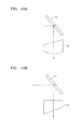
- FIG. 7A illustrates an example of a path through which measurement light travels in an optical probe.
- FIG. 7B illustrates an example of a path through which reflection light travels in an optical probe.
- FIG. 8A illustrates another example of a path through which measurement light travels in an optical probe.
- FIG. 8B illustrates another example of a path through which reflection light travels in an optical probe.
- FIG. 9 illustrates another example of a path through which measurement light travels in an optical probe.
- FIGS. 10A and 10B illustrate internal configurations of other examples of optical probes.
- FIG. 1 illustrates a configuration of an example of an optical coherence tomography (OCT) apparatus.
- the OCT apparatus includes a light generator 110, a light coupler 120, an optical probe 130, a detector 140, and an image signal processor 150. The operation of the OCT apparatus will be described with reference to FIG. 1 below.
- the light generator 110 generates light and transmits the light to the light coupler 120.
- the light coupler 120 includes a beam splitter 122 and a reference mirror 124.
- the light transmitted from the light generator 110 is split into a measurement light and a reference light in the beam splitter 122.
- the measurement light is transmitted to the optical probe 130, and the reference light is transmitted to the reference mirror 124 and reflected from the reference mirror 124.
- the reflected reference light returns to the beam splitter 122.
- the measurement light transmitted to the optical probe 130 is irradiated onto a subject 10 of which an internal tomographic image is to be captured through the optical probe 130.
- a response light generated by the irradiated measurement light reflecting from the subject 10 is transmitted to the beam splitter 122 of the light coupler 120 through the optical probe 130.
- the transmitted response light and the reference light reflected from the reference mirror 124 interfere with each other in the beam splitter 122, and the detector 140 detects an interference signal.
- the detector 140 transmits the detected interference signal to the image signal processor 150, and the image signal processor 150 converts the detected interference signal into an image signal representing a tomographic image of the subject 10.
- the full range OCT apparatus changes an optical path length of a measurement light as a point of the subject 10 onto which the measurement light is irradiated moves in a lateral direction, thereby modulating the optical path length of the measurement light as the point of the subject 10 onto which the measurement light is irradiated moves in the lateral direction.
- This optical path length modulation modulates the phase of the interference signal detected by the detector 140.
- a scan is performed by continuously moving a point of the subject 10 onto which the measurement light is irradiated by the same distance in a lateral direction.
- optical path length modulation and thus phase modulation of the interference signal detected by the detector 140, is performed by increasing the optical path length of the measurement light by the same length whenever the point of the subject 10 onto which the measurement light is irradiated moves in the lateral direction.
- the optical path length is a value obtained by multiplying a refractive index n of a medium through which the measurement light travels by a distance l the measurement light travels through the medium having the refractive index n. That is, the optical path length is equal to a distance the measurement light would travel through a vacuum during the time it takes for the measurement light to travel through the medium having the refractive index n.
- the optical probe 130 moves a point of the subject 10 onto which the measurement light is irradiated in the lateral direction while changing the optical path length of the measurement light.
- the optical probe 130 includes a collimator lens 132, a galvano scanner 134, an optical path length control element 136, and a lens 138.
- the galvano scanner 134 is a mirror that can be rotated by a predetermined degree of rotation about a predetermined axis of rotation, and may be a microelectromechanical system (MEMS) scanner that obtains a driving power necessary for rotation from a MEMS.
- MEMS microelectromechanical system
- the optical path length control element 136 may be formed in various shapes of a single material having a uniform refractive index, or two or more materials having different refractive indexes, and controls the optical path length to be changed according to a point of the optical path length control element 136 through which the measurement light passes.
- the measurement light transmitted from the beam splitter 122 is collimated by passing through the collimator lens 132 of the optical probe 130.
- the measurement light that has passed through the collimator lens 132 is reflected from the galvano scanner 134 in a particular direction determined by a rotary position of the galvano scanner 134 about an axis of rotation of the galvano scanner 134, and then the reflected measurement light sequentially passes through the optical path length control element 136 and the lens 138, and is irradiated onto the subject 10.
- the galvano scanner 134 rotates about the predetermined axis of rotation, the point of the subject 10 onto which the measurement light is irradiated moves in the lateral direction, thereby changing the direction of the measurement light, and also a point of the optical path length control element 136 through which the measurement light passes moves, thereby changing the optical path length of the measurement light.
- the optical probe 130 may include a housing (not shown) that contains the collimator lens 132, the galvano scanner 134, the optical path length control element 136, and the lens 138.
- the measurement light that has passed through the optical path length control element 136 and the lens 138 is output from an opening of the housing and is then irradiated onto the subject 10.
- the opening of the housing may be referred to as a light opening.
- FIG. 2 illustrates an example of a path through which the measurement light travels in the optical probe 130.
- a direction of the measurement light is moved by a predetermined distance in the lateral direction as the galvano scanner 134 rotates by a predetermined degree of rotation about an axis of rotation 134a.
- the galvano scanner 134 rotates to change the direction of the measurement light from a first direction to an N-th direction.
- a measurement light of the first direction travels through an optical path length corresponding to d 11 and d 12 in FIG. 2
- a measurement light of the second direction travels through an optical path length corresponding to d 21 and d 22 in FIG.
- d i d i ⁇ 1 + n ⁇ d i ⁇ 2
- n denotes a refractive index of a material of the optical path length control element 136.
- a difference between optical path lengths of two measurement lights of adjacent directions that is, a difference between an optical path length of a measurement light of an (i+1)-th direction and an optical path length of a measurement light of an i-th direction, may be expressed by the following Equation 2.
- ⁇ ⁇ x d i + 1 - d i
- ⁇ x is the amount the optical path length of the measurement light changes, i.e., the amount by the optical path length is modulated, each time the galvano scanner 134 moves the direction of the measurement light by the predetermined distance in the lateral direction.
- ⁇ x may be considered to be a modulation index of the optical path length modulation.
- the modulation index ⁇ x may be changed by adjusting an angle between an inclined plane of the optical path length control element 136 and a base plane thereof, the refractive index of the material of the optical path length control element 136, a position of the axis of rotation 134a of the galvano scanner 134, or a curvature of the reflective surface of the galvano scanner 134.
- Equation 3 a power of an interference signal that is received from the detector 140 of the OCT apparatus of FIG. 1 is represented by the following Equation 3.
- Equation 3 x denotes a coordinate of a point of the subject 10 onto which the measurement light is irradiated, assuming that the lateral direction in which a direction of the measurement light moves is an X axis, k i denotes a wavenumber of the measurement light of the i-th direction, I D denotes the power of the interference signal that is received from the detector 140, S ( k i ) denotes an amplitude of each wavenumber of a light source, ⁇ n ( x ) denotes an amplitude of the light source in the lateral direction, ⁇ z denotes a difference value obtained by subtracting a distance that light travels from the beam splitter 122 to the reference mirror from a distance that light travels from the beam splitter 122 to the subject 10, and DC denotes a DC component.
- Equation 4 is obtained by rewriting Equation 3 with terms including a complex number in exponential form using Euler's formula.
- I D k i ⁇ x A k i ⁇ x ⁇ e 2 ⁇ jf B ⁇ x + A * k i ⁇ x ⁇ e - 2 ⁇ jf B ⁇ x + DC
- an optical path length is increased by a constant value when a direction of the measurement light is changed as expressed by the following Equation 5.
- an increase in the optical path length when the direction of the measurement light is changed from the first direction to the second direction is the same as an increase in the optical path length when the direction of the measurement light is changed from the second direction to a third direction.
- the modulation index of the optical path length modulation may be changed by adjusting an angle between the inclined plane of the optical path length control element 136 and the base plane thereof, the refractive index of the material of the optical path length control element 136, the position of the axis of rotation 134a of the galvano scanner 134, or a curvature of the reflective surface of the galvano scanner 134.
- Conventional coherence tomography apparatuses do not include a an element corresponding to the optical path length control element 136, but use a method of moving the axis of rotation of a galvano scanner to make constant a difference ⁇ x between optical path lengths of two measurement lights of adjacent directions in performing optical path length modulation.
- the conventional coherence tomography apparatuses have a limit in terms of miniaturization thereof since a space for moving the axis of rotation of the galvano scanner is required.
- a MEMS scanner having a total width of 3 mm and a mirror having a diameter of 1.5 mm is used as the galvano scanner in an optical probe of a conventional coherence tomography apparatus
- an additional width of 500 ⁇ m through 700 ⁇ m is required for moving the axis of rotation of the galvano scanner, requiring a total width of 3.5 mm to 3.7 mm. Accordingly, such an optical probe cannot be inserted into a working channel of an endoscope having a standard diameter of 2.8 mm to 3.0 mm.
- optical path length modulation may be performed without moving the axis of rotation of the galvano scanner 134 by including the optical path length control element 136, and accordingly a full range OCT apparatus may be implemented without increasing the width of the optical probe 130.
- optical path length control element 136 and the optical probe 130 including the optical path length control element 136 will described below with reference to FIGS. 3A through 3C .
- FIGS. 3A through 3C illustrate internal configurations of examples of optical probes including the optical path length control element 136.
- FIGS. 3A through 3C illustrate examples of optical probes in which locations and orientations of the optical path length control element 136 differ in each example from the example illustrated in FIGS. 1 and 2 .
- the optical path length control element 136 is disposed below the lens 138, compared to being disposed above the lens 138 in the example illustrated in FIGS. 1 and 2 , but is oriented the same as in the example illustrated in FIGS. 1 and 2 .
- the location where the optical path length control element 136 is disposed is the same as in the example illustrated in FIGS. 1 and 2 , but the left and right sides of the optical path length control element 136 are reversed compared to the example illustrated in FIGS. 1 and 2 , i.e., the optical path length control element 136 is flipped in the horizontal direction in the example illustrated in FIG. 3B compared to the example illustrated in FIGS. 1 and 2 .
- the location where the optical path length control element 136 is disposed is the same as in the example illustrated in FIGS. 1 and 2 , but the upper and lower sides of the optical path length control element 136 are reversed compared to the example, illustrated in FIGS. 1 and 2 , i.e., the optical path length control element 136 is flipped in the vertical direction in the example illustrated in FIG. 3C compared to the example illustrated in FIGS. 1 and 2 .
- the location and the orientation of the optical path length control element 136 in the optical probe may be changed in various ways if necessary.
- the modulation index of the optical path length modulation may be changed by adjusting an angle between the inclined plane of the optical path length control element 136 and the base plane thereof, the refractive index of the material of the optical path length control element 136, the position of the axis of rotation 134a of the galvano scanner 134, or a curvature of the reflective surface of the galvano scanner 134.
- FIGS. 4A through 4C illustrate cross-sectional views of other examples of the optical path length control element 136.
- FIGS. 4A through 4C illustrate examples in which the optical path length control element 136 made of two different materials having different refractive indexes.
- reference numerals 136a and 136b indicate two different materials having different refractive indexes.
- a boundary line between the material 136a and the material 136b is a curved line extending from the upper surface of the optical path length control element 136 into the interior of the optical path length control element 136 and back to the upper surface of the optical path length control element 136.
- a boundary line between the material 136a and the material 136b is a straight line parallel to the upper surface of the optical path length control element 136.
- a boundary line between the material 136a and the material 136b is a straight line parallel to the bottom surface of the optical path length control element 136.
- a material that forms the optical path length control element 136 may be changed if necessary.
- the modulation index of the optical path length modulation may be changed by adjusting an angle between the inclined plane of the optical path length control element 136 and the base plane thereof, the refractive indexes of the materials of the optical path length control element 136, the position of the axis of rotation 134a of the galvano scanner 134, or a curvature of the reflective surface of the galvano scanner 134.
- the optical path length control element 136 is made of two different materials 136a and 136b having different refractive indexes
- the optical path length control element 136 may be made of three or more different materials having different refractive indexes.
- FIGS. 5A through 5E illustrate cross-sectional views of other examples of the optical path length control element 136 having different shapes.
- the cross-section of the optical path length control element 136 has a wedge shape.
- the cross-section of the optical path length control element 136 may have different shapes.
- the upper and lower surfaces of the optical path length control element 136 have a meniscus shape.
- only one of the upper and lower surfaces of the optical path length control element 136 may have a meniscus shape.
- the upper surface of the optical path length control element 136 has protrusions 136c.
- the cross-section of the optical path length control element 136 has a rectangular formed by two wedge-shaped layers 136a and 136b made of two different materials having different refractive indexes.
- the cross-section of the optical path length control element 136 has a rectangular shape, and a refractive index of the optical path length control element 136 gradually changes in a direction parallel to the upper and lower surfaces of the optical path length control element 136 as indicated by the gradually increasing shades of gray indicating different refractive indexes.
- the different shades of gray indicate different refractive indexes.
- the refractive index may change in discrete steps as illustrated in FIG. 5D , or may change continuously.
- the cross-section of the optical path length control element 136 has a stair shape.
- a modulation degree of the optical path length modulation may be changed by adjusting an angle between the inclined plane of the optical path length control element 136 and the base plane thereof, the refractive index of the material of the optical path length control element 136, the position of the axis of rotation 134a of the galvano scanner 134, or a curvature of the reflective surface of the galvano scanner 134.
- FIG. 6 illustrates an internal configuration of an example of an optical probe including a piezoelectric actuator 135.
- the optical probe illustrated in FIG. 6 changes the direction of a measurement light using the piezoelectric actuator 135, rather than the galvano scanner 134 used in the optical probe 130 illustrated in FIG. 1 .
- an electrical signal is applied to piezoelectric elements 135a disposed in the upper portion and the lower portion of the piezoelectric actuator 135, the piezoelectric elements 135a are bent upward or downward, and a supporting layer 135b of the piezoelectric actuator 135 that supports the piezoelectric elements 135a is also bent upward or downward as the piezoelectric elements 135a are bent upward or downward.
- the supporting layer 135b includes an optical fiber 135c through which the measurement light is transmitted, and a direction of the measurement light that is output from the optical fiber 135c is changed upward or downward since the optical fiber 135c is bent upward or downward together with the supporting layer 135b.
- the measurement light of different directions that is output from the optical fiber 135c is collimated by a collimator lens 139, and then sequentially passes through an optical path length control element 136 and a lens 138, and is irradiated onto a subject (not illustrated in FIG. 6 ).
- optical path length modulation by rotating a galvano scanner about its axis of rotation like the galvano scanner 134 in the optical probe 130 illustrated in FIG. 1 is impossible because such a galvano scanner is not used in the optical probe in FIG. 6 .
- the optical path length control element 136 by disposing the optical path length control element 136 in a path of the measurement light of different directions that is output from the optical fiber 135c as illustrated in FIG. 6 , the optical path length modulation described above may be performed.
- the optical path length control element 136 in FIG. 6 may have any of the various forms illustrated in FIGS. 4A through 5E . Accordingly, by using the piezoelectric actuator 135 and the optical path length control element 136, a full range OCT apparatus may be implemented using an optical probe in which moving the axis of rotation of a galvano scanner is impossible.
- Optical path length modulation for performing phase modulation may also be performed by changing a diameter of measurement as will be described in greater detail below.
- FIG. 7A illustrates an example of a path through which measurement light travels in an optical probe
- FIG. 7B illustrates an example of a path through which response light, i.e., reflection light, travels in an optical probe.
- the measurement light is reflected from the galvano scanner 134 in a first direction determined by a first rotary position of the galvano scanner 134 about the axis of rotation 134a, and the measurement light of the first direction is irradiated onto the subject 10.
- the optical path length control element 136 is not located in a path of the measurement light. Accordingly, the measurement light is irradiated onto the subject 10 without being influenced by the optical path length control element 136.
- reflection light produced by the measurement light reflecting from the subject 10 is reflected from the galvano scanner 134 without being influenced by the optical path length control element 136, and then travels to the outside of the optical probe.
- FIG. 8A illustrates another example of a path through which measurement light travels in an optical probe
- FIG. 8B illustrates another example of a path through which response light, i.e., reflection light, travels in an optical probe.
- the galvano scanner 134 has rotated counterclockwise about the axis of rotation 134a compared to FIG. 7A to a second rotary position about the axis of rotation 134a, and accordingly a direction of the measurement light reflected by the galvano scanner 134 has moved to the right compared to the direction of the measurement light in FIG. 7A .
- the measurement light is reflected from the galvano scanner 134 in a second direction different from the first direction of the measurement light in FIG. 7A , and the measurement light of the second direction is irradiated onto the subject 10.
- the optical path length control element 136 is located in a path of the measurement light.
- the optical path length control element 136 may be made in various shapes of one material having a constant refractive index or two or more materials having different refractive indexes. Alternatively, the optical path length control element 136 may be made of a material that blocks light.
- reflection light produced by the measurement light reflecting from the subject 10 is reflected from the galvano scanner 134, and then travels to the outside of the optical probe.
- the diameter of the reflection light illustrated in FIG. 8B is also reduced compared to FIG. 7B due to the optical path length control element 136 refracting or blocking a portion of the measurement light in FIG. 8A .
- the optical path length control element 136 changes the diameters of the measurement light and the reflection light, which substantially changes the length of an optical path. The reason that the changes in the diameters of the measurement light and the reflection light change the length of the optical path will now be described in detail with reference to FIGS. 7B and 8B .
- FIG. 9 illustrates another example of a path through which measurement light travels in an optical probe.
- the diameter of measurement light of a first direction is r 1
- the diameter of measurement light of a second direction is r 2
- the diameter of measurement light of an N-th direction is r N .
- the diameters are changed using the optical path length control element 136 as described above with reference to FIGS. 7A through 8B . If the diameter of a measurement light of an i-th direction is r i (where i is 1, 2, ...
- a difference between diameters of two measurement lights of adjacent directions (that is, a measurement light of an i+1-th direction and a measurement light of an i-th direction) may be expressed by the following Equation 6.
- ⁇ ⁇ r r i + 1 - r i
- Equation 6 If ⁇ r of Equation 6 is 1 f B , the optical path length modulation for performing phase modulation may be performed according to Equations 3 and 4 described above. Refer to the descriptions of Equations 3 and 4 above for more details.
- Another optical probe may include a lens having a modified shape that simultaneously performs a function of a lens and a function of an optical path length control element. Examples of such an optical probe will be described in greater detail below with reference to FIGS. 10A and 10B .
- FIGS. 10A and 10B illustrate internal configurations of other examples of optical probes. Comparing FIGS. 10A and 10B with FIGS. 3A through 3C , the optical probes of FIGS. 3A through 3C include the optical path length control element 136 and the lens 138 as separate elements, whereas the optical probes of FIGS. 10A and 10B do not include the optical path length control element 136, but include only the lens 138. In this case, one surface of the lens 138 of FIGS. 10A and 10B is formed as an inclined plane like the inclined plane of the optical path length control element 136 of FIGS. 3A to 3C , and accordingly the shape of the lens 138 of FIGS.
- FIGS. 10A and 10B is similar to a shape obtained by combining the optical path length control element 136 of FIGS. 3A to 3C with an upper or lower surface of the lens 138 of FIGS. 3A through 3C . That is, the lens 138 of FIGS. 10A and 10B simultaneously performs the functions of the optical path length control element 136 and the lens 138 of FIGS. 3A through 3C .
- the lens 138 of FIGS. 10A and 10B enables a configuration of an optical probe to be simplified by providing the function changing an optical path length by modifying a lens.
Landscapes
- Physics & Mathematics (AREA)
- General Physics & Mathematics (AREA)
- Optics & Photonics (AREA)
- Chemical & Material Sciences (AREA)
- Dispersion Chemistry (AREA)
- Health & Medical Sciences (AREA)
- General Health & Medical Sciences (AREA)
- Nuclear Medicine, Radiotherapy & Molecular Imaging (AREA)
- Radiology & Medical Imaging (AREA)
- Investigating Or Analysing Materials By Optical Means (AREA)
Abstract
Description
- 1. Field
- This application relates to an optical probe having a controllable optical path length and an optical coherence tomography (OCT) apparatus including the optical probe.
- 2. Description of Related Art
- Recently, methods and apparatuses that are able to observe internal structures of subjects such as human tissues or various materials have been widely used. Examples of the apparatuses include an internal transmission image generating apparatus and a tomographic image generating apparatus such as an X-ray system, a computerized tomography (CT) scanner, a magnetic resonance image (MRI) apparatus, and an ultrasound system. These apparatuses may determine causes, locations, and progress of various diseases without having to directly incise internal structures of human or animal bodies, and accordingly hold a key position in the medical field. In these diagnosis apparatuses, safety in relation to human or animal bodies, acquisition of high resolution images, reasonable cost, and convenience of movement and use are important factors.
- In particular, an optical coherence tomography (OCT) apparatus is an apparatus capable of capturing an internal structure of a subject based on interference between light irradiated on the subject and then reflected therefrom, and a reference light. The OCT apparatus has been widely used because it is capable of obtaining high resolution images and is harmless to human bodies.
- In one general aspect, an optical probe for irradiating light onto a subject includes an optical path control unit configured to receive light from outside the optical probe, and change a path of the light within the optical probe; an optical path length control element configured to receive the light having the changed path from the optical path control unit, and change an optical path length of the light as the optical path control unit changes the path of the light; and an optical output unit configured to receive the light having the changed optical path length from the optical path length control element, and output the light. Thereby the optical path length of the light is modulated according to (in dependence of) the changed path.
- The optical output unit may be further configured to irradiate the light output from the optical output unit onto a subject; the optical path control unit may be further configured to change the path of the light to repeatedly move a point where the light output from the optical output unit is irradiated onto the subject by a predetermined distance in a predetermined direction; and the optical path length control element may be further configured to uniformly change the optical path length each time the point where the light is irradiated onto the subject moves. Accordingly, the optical path length of the light may be modulated repeatedly in the same way as the point onto which the measurement light is irradiated moves by the same distance in the same direction. This optical path length modulation may thus modulate the phase of an interference signal.
- The optical path length control element may be further configured to transmit the light having the changed path through the optical path length control element, and change the optical path length of the light according to a point of the optical path length control element through which the light passes. This e.g. allows for a simple implementation of the optical path length control element with transparent materials.
- The optical path length control element may have a nonuniform thickness, and may include a material having a uniform refractive index. Thus, the characteristic of changing the optical path length can be predetermined by using a varying thickness of the optical path length control element that may be manufactured from one (transparent) material.
- A cross-section of the optical path length control element may have a wedge shape. This is a particularly easy to manufacture shape that has a directly proportional dependence of optical depth with distance along the wedge. In particular, this provides for a continuous change with the distance.
- At least one surface of the optical path length control element may have a meniscus shape. This shape has the advantage of having focusing properties.
- The optical path length control element may include at least two materials having different refractive indexes. Hence, the optical path length can more precisely be predetermined.
- The optical path length control element may include protrusions on a surface of the optical path length control element. This has the advantage that highlighted focused sub-beams of light respectively corresponding to the protrusions may be generated when a beam of light fall on the optical path length control element.
- The optical path length control element may be further configured to change the optical path length of the light having the changed path by changing a diameter of the light having the changed path by blocking a portion of the light having the changed path. Therefore, the diameter of the light can be adjusted to change for the changed path.
- The optical path length control element may be further configured to change the optical path length of the light have the changed path by changing the diameter of the light having the changed path according to the changed path. This has the advantage that the diameter of the light is changes in dependence of the changed path, for example proportional to a change in angle in a particular direction.
- The optical path control unit may include a mirror configured to rotate by a predetermined degree of rotation about a fixed axis of rotation each time the optical path control unit changes the path of the light. A mirror is a very simple and easy to control implementation of the optical path control unit.
- In another general aspect, an optical coherence tomography (OCT) apparatus for scanning a subject by irradiating light onto the subject includes a light generator configured to generate light; a light coupler configured to split the generated light into a measurement light and a reference light, transmit the measurement light to an optical probe, and receive a response light from the optical probe, the response light being produced by the measurement light reflecting from the subject; a detector configured to detect an interference signal generated by interference between the response signal and the reference signal; and an image signal processor configured to generate a tomographic image of the subject from the detected interference signal; wherein the optical probe includes an optical path control unit configured to receive the measurement light from the light coupler, and change a path of the measurement light within the optical probe; an optical path length control element configured to receive the measurement light having the changed path from the optical path control unit, and change an optical path length of the measurement light as the optical path control unit changes the path of the measurement light; and an optical output unit configured to receive the measurement light having the changed optical path length from the optical path length control element, and output the measurement light. Therefore, an optical coherence tomography apparatus is provided that comprises an optical probe according to the invention.
- The optical output unit may be further configured to irradiate the measurement light output from the optical output unit onto the subject; the optical path control unit may be further configured to change the path of the measurement light to repeatedly move a point where the measurement light output from the optical output unit is irradiated onto the subject by a predetermined distance in a predetermined direction; and the optical path length control element may be further configured to uniformly change the optical path length each time the point where the measurement light is irradiated onto the subject moves. The advantage(s) of this feature have already been given above.
- The optical path length control element may be further configured to transmit the measurement light having the changed path through the optical path length control element, and change the optical path length of the measurement according to a point of the optical path length control element through which the measurement light passes. The advantage(s) of this feature have already been given above.
- The optical path length control element may have a nonuniform thickness, and may include a material having a uniform refractive index. The advantage(s) of this feature have already been given above.
- A cross-section of the optical path length control element may have a wedge shape. The advantage(s) of this feature have already been given above.
- At least one surface of the optical path length control element may have a meniscus shape. The advantage(s) of this feature have already been given above.
- The optical path length control element may include at least two materials having different refractive indexes. The advantage(s) of this feature have already been given above.
- The optical path length control element may include protrusions on a surface of the optical path length control element. The advantage(s) of this feature have already been given above.
- The optical path length control element may be further configured to change the optical path length of the measurement light having the changed path by changing a diameter of the measurement light having the changed patch by blocking a portion of the measurement light having the changed path. The advantage(s) of this feature have already been given above.
- The optical path length control element may be further configured to change the optical path length of the measurement light having the changed path by changing the diameter of the measurement light having the changed patch according to the changed path. The advantage(s) of this feature have already been given above.
- The optical path control unit may include a mirror configured to rotate by a predetermined degree of rotation about a fixed axis of rotation each time the optical path control unit changes the path of the measurement light. The advantage(s) of this feature have already been given above.
- In another general aspect, an optical probe includes an optical path control unit configured to receive light, and control a path of the light; and an optical path length modulator having no moving parts and being configured to receive the light having the controlled path from the optical path control unit, and modulate an optical path length of the light having the controlled path as the optical path control unit controls the path of the light. This has the advantage that the optical path length modulator can be provided in a fixed predetermined precise position.
- The optical path length modulator may be a passive optical path length modulator configured to modulate the optical path length of the light having the controlled path without any external control as the optical path control unit controls the path of the light. Accordingly, the optical path length only depends on the changed path controlled by the optical path control unit.
- The optical path length modulator may be further configured to modulate the optical path length of the light having the controlled path according to a characteristic of the optical path length modulator depending on a point where the light having the controlled path is incident on the optical path length modulator. Thus, the change in optical path length depends on the particular position where the light incidents on the optical path length modulator.
- The characteristic of the optical path length modulator may be an optical path length of the optical path length modulator. Hence, the optical path length is changed.
- Other features and aspects will be apparent from the following detailed description, the drawings, and the claims.
-
FIG. 1 illustrates a configuration of an example of an optical coherence tomography (OCT) apparatus. -
FIG. 2 illustrates an example of a path through which measurement light travels in an optical probe. -
FIGS. 3A through 3C illustrate internal configurations of examples of optical probes including an optical path length control element. -
FIGS. 4A through 4C illustrate cross-sectional views of other examples of the optical path length control element. -
FIGS. 5A through 5E illustrate cross-sectional views of other examples of the optical path length control element having different shapes. -
FIG. 6 illustrates an internal configuration of an example of an optical probe including a piezoelectric actuator. -
FIG. 7A illustrates an example of a path through which measurement light travels in an optical probe. -
FIG. 7B illustrates an example of a path through which reflection light travels in an optical probe. -
FIG. 8A illustrates another example of a path through which measurement light travels in an optical probe. -
FIG. 8B illustrates another example of a path through which reflection light travels in an optical probe. -
FIG. 9 illustrates another example of a path through which measurement light travels in an optical probe. -
FIGS. 10A and 10B illustrate internal configurations of other examples of optical probes. - The following detailed description is provided to assist the reader in gaining a comprehensive understanding of the methods, apparatuses, and/or systems described herein. However, various changes, modifications, and equivalents of the methods, apparatuses, and/or systems described herein will be apparent to one of ordinary skill in the art. Also, descriptions of functions and constructions that are well known to one of ordinary skill in the art may be omitted for increased clarity and conciseness.
- Throughout the drawings and the detailed description, the same reference numerals refer to the same elements. The drawings may not be to scale, and the relative size, proportions, and depiction of elements in the drawings may be exaggerated for clarity, illustration, and convenience.
-
FIG. 1 illustrates a configuration of an example of an optical coherence tomography (OCT) apparatus. Referring toFIG. 1 , the OCT apparatus includes alight generator 110, alight coupler 120, anoptical probe 130, adetector 140, and animage signal processor 150. The operation of the OCT apparatus will be described with reference toFIG. 1 below. - The
light generator 110 generates light and transmits the light to thelight coupler 120. Thelight coupler 120 includes abeam splitter 122 and areference mirror 124. The light transmitted from thelight generator 110 is split into a measurement light and a reference light in thebeam splitter 122. The measurement light is transmitted to theoptical probe 130, and the reference light is transmitted to thereference mirror 124 and reflected from thereference mirror 124. The reflected reference light returns to thebeam splitter 122. The measurement light transmitted to theoptical probe 130 is irradiated onto a subject 10 of which an internal tomographic image is to be captured through theoptical probe 130. A response light generated by the irradiated measurement light reflecting from the subject 10 is transmitted to thebeam splitter 122 of thelight coupler 120 through theoptical probe 130. The transmitted response light and the reference light reflected from thereference mirror 124 interfere with each other in thebeam splitter 122, and thedetector 140 detects an interference signal. Thedetector 140 transmits the detected interference signal to theimage signal processor 150, and theimage signal processor 150 converts the detected interference signal into an image signal representing a tomographic image of the subject 10. - Since this example relates to a full range OCT apparatus, the full range OCT apparatus and an internal configuration and an operation of the
optical probe 130 used for implementing the full range OCT apparatus will be described below. - The full range OCT apparatus changes an optical path length of a measurement light as a point of the subject 10 onto which the measurement light is irradiated moves in a lateral direction, thereby modulating the optical path length of the measurement light as the point of the subject 10 onto which the measurement light is irradiated moves in the lateral direction. This optical path length modulation modulates the phase of the interference signal detected by the
detector 140. In greater detail, a scan is performed by continuously moving a point of the subject 10 onto which the measurement light is irradiated by the same distance in a lateral direction. In addition, optical path length modulation, and thus phase modulation of the interference signal detected by thedetector 140, is performed by increasing the optical path length of the measurement light by the same length whenever the point of the subject 10 onto which the measurement light is irradiated moves in the lateral direction. A direction in which the measurement light is irradiated onto the subject 10, that is, a depth direction of the subject 10, is referred to as an axial direction, and a direction perpendicular to the axial direction is referred to as a lateral direction. - The optical path length is a value obtained by multiplying a refractive index n of a medium through which the measurement light travels by a distance l the measurement light travels through the medium having the refractive index n. That is, the optical path length is equal to a distance the measurement light would travel through a vacuum during the time it takes for the measurement light to travel through the medium having the refractive index n.
- Accordingly, as described above, the
optical probe 130 moves a point of the subject 10 onto which the measurement light is irradiated in the lateral direction while changing the optical path length of the measurement light. - Referring to
FIG. 1 , theoptical probe 130 includes acollimator lens 132, agalvano scanner 134, an optical pathlength control element 136, and alens 138. Thegalvano scanner 134 is a mirror that can be rotated by a predetermined degree of rotation about a predetermined axis of rotation, and may be a microelectromechanical system (MEMS) scanner that obtains a driving power necessary for rotation from a MEMS. The optical pathlength control element 136 may be formed in various shapes of a single material having a uniform refractive index, or two or more materials having different refractive indexes, and controls the optical path length to be changed according to a point of the optical pathlength control element 136 through which the measurement light passes. - The measurement light transmitted from the
beam splitter 122 is collimated by passing through thecollimator lens 132 of theoptical probe 130. The measurement light that has passed through thecollimator lens 132 is reflected from thegalvano scanner 134 in a particular direction determined by a rotary position of thegalvano scanner 134 about an axis of rotation of thegalvano scanner 134, and then the reflected measurement light sequentially passes through the optical pathlength control element 136 and thelens 138, and is irradiated onto the subject 10. As thegalvano scanner 134 rotates about the predetermined axis of rotation, the point of the subject 10 onto which the measurement light is irradiated moves in the lateral direction, thereby changing the direction of the measurement light, and also a point of the optical pathlength control element 136 through which the measurement light passes moves, thereby changing the optical path length of the measurement light. - Although not illustrated in
FIG. 1 , theoptical probe 130 may include a housing (not shown) that contains thecollimator lens 132, thegalvano scanner 134, the optical pathlength control element 136, and thelens 138. In this case, the measurement light that has passed through the optical pathlength control element 136 and thelens 138 is output from an opening of the housing and is then irradiated onto the subject 10. Thus, the opening of the housing may be referred to as a light opening. - A method of scanning the measurement light in the lateral direction on the subject 10 while changing the optical path length will now be explained with reference to
FIG. 2 . -
FIG. 2 illustrates an example of a path through which the measurement light travels in theoptical probe 130. Referring toFIG. 2 , a direction of the measurement light is moved by a predetermined distance in the lateral direction as thegalvano scanner 134 rotates by a predetermined degree of rotation about an axis ofrotation 134a. Thegalvano scanner 134 rotates to change the direction of the measurement light from a first direction to an N-th direction. A measurement light of the first direction travels through an optical path length corresponding to d11 and d12 inFIG. 2 , a measurement light of the second direction travels through an optical path length corresponding to d21 and d22 inFIG. 2 , and a measurement light of the N-th direction travels through an optical path length corresponding to dN1 and dN2 inFIG. 2 . If it is assumed that di is an optical path length through which the measurement light travels after being reflected from thegalvano scanner 134 until it passes through the optical pathlength control element 136, di may be expressed by the followingEquation 1.
- In
Equation 1, n denotes a refractive index of a material of the optical pathlength control element 136. - A difference between optical path lengths of two measurement lights of adjacent directions, that is, a difference between an optical path length of a measurement light of an (i+1)-th direction and an optical path length of a measurement light of an i-th direction, may be expressed by the following Equation 2.

- Thus, Δx is the amount the optical path length of the measurement light changes, i.e., the amount by the optical path length is modulated, each time the
galvano scanner 134 moves the direction of the measurement light by the predetermined distance in the lateral direction. Accordingly, Δx may be considered to be a modulation index of the optical path length modulation. The modulation index Δx may be changed by adjusting an angle between an inclined plane of the optical pathlength control element 136 and a base plane thereof, the refractive index of the material of the optical pathlength control element 136, a position of the axis ofrotation 134a of thegalvano scanner 134, or a curvature of the reflective surface of thegalvano scanner 134. A detailed method of performing the optical path length modulation using the modulation index Δx will be explained in detail below. - If Δx of Equation 2 is

detector 140 of the OCT apparatus ofFIG. 1 is represented by the following Equation 3.
- In Equation 3, x denotes a coordinate of a point of the subject 10 onto which the measurement light is irradiated, assuming that the lateral direction in which a direction of the measurement light moves is an X axis, ki denotes a wavenumber of the measurement light of the i-th direction, ID denotes the power of the interference signal that is received from the
detector 140, S(ki ) denotes an amplitude of each wavenumber of a light source, ρ n (x) denotes an amplitude of the light source in the lateral direction, Δz denotes a difference value obtained by subtracting a distance that light travels from thebeam splitter 122 to the reference mirror from a distance that light travels from thebeam splitter 122 to the subject 10, and DC denotes a DC component. - The following Equation 4 is obtained by rewriting Equation 3 with terms including a complex number in exponential form using Euler's formula.

- In order to perform the optical path length modulation, as described above, an optical path length is increased by a constant value when a direction of the measurement light is changed as expressed by the following Equation 5.

- For example, an increase in the optical path length when the direction of the measurement light is changed from the first direction to the second direction is the same as an increase in the optical path length when the direction of the measurement light is changed from the second direction to a third direction.
- Also, as described above, the modulation index of the optical path length modulation may be changed by adjusting an angle between the inclined plane of the optical path
length control element 136 and the base plane thereof, the refractive index of the material of the optical pathlength control element 136, the position of the axis ofrotation 134a of thegalvano scanner 134, or a curvature of the reflective surface of thegalvano scanner 134. - Conventional coherence tomography apparatuses do not include a an element corresponding to the optical path
length control element 136, but use a method of moving the axis of rotation of a galvano scanner to make constant a difference Δx between optical path lengths of two measurement lights of adjacent directions in performing optical path length modulation. - Thus, the conventional coherence tomography apparatuses have a limit in terms of miniaturization thereof since a space for moving the axis of rotation of the galvano scanner is required. For example, when a MEMS scanner having a total width of 3 mm and a mirror having a diameter of 1.5 mm is used as the galvano scanner in an optical probe of a conventional coherence tomography apparatus, an additional width of 500 µm through 700 µm is required for moving the axis of rotation of the galvano scanner, requiring a total width of 3.5 mm to 3.7 mm. Accordingly, such an optical probe cannot be inserted into a working channel of an endoscope having a standard diameter of 2.8 mm to 3.0 mm. However, in the example described herein, optical path length modulation may be performed without moving the axis of rotation of the
galvano scanner 134 by including the optical pathlength control element 136, and accordingly a full range OCT apparatus may be implemented without increasing the width of theoptical probe 130. - Various examples of the optical path
length control element 136 and theoptical probe 130 including the optical pathlength control element 136 will described below with reference toFIGS. 3A through 3C . -
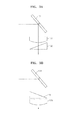
FIGS. 3A through 3C illustrate internal configurations of examples of optical probes including the optical pathlength control element 136. In greater detail,FIGS. 3A through 3C illustrate examples of optical probes in which locations and orientations of the optical pathlength control element 136 differ in each example from the example illustrated inFIGS. 1 and 2 . - Referring to
FIG. 3A , the optical pathlength control element 136 is disposed below thelens 138, compared to being disposed above thelens 138 in the example illustrated inFIGS. 1 and 2 , but is oriented the same as in the example illustrated inFIGS. 1 and 2 . - Referring to
FIG. 3B , the location where the optical pathlength control element 136 is disposed is the same as in the example illustrated inFIGS. 1 and 2 , but the left and right sides of the optical pathlength control element 136 are reversed compared to the example illustrated inFIGS. 1 and 2 , i.e., the optical pathlength control element 136 is flipped in the horizontal direction in the example illustrated inFIG. 3B compared to the example illustrated inFIGS. 1 and 2 . - Referring to
FIG. 3C , the location where the optical pathlength control element 136 is disposed is the same as in the example illustrated inFIGS. 1 and 2 , but the upper and lower sides of the optical pathlength control element 136 are reversed compared to the example, illustrated inFIGS. 1 and 2 , i.e., the optical pathlength control element 136 is flipped in the vertical direction in the example illustrated inFIG. 3C compared to the example illustrated inFIGS. 1 and 2 . - Accordingly, as described above, the location and the orientation of the optical path
length control element 136 in the optical probe may be changed in various ways if necessary. The modulation index of the optical path length modulation may be changed by adjusting an angle between the inclined plane of the optical pathlength control element 136 and the base plane thereof, the refractive index of the material of the optical pathlength control element 136, the position of the axis ofrotation 134a of thegalvano scanner 134, or a curvature of the reflective surface of thegalvano scanner 134. -
FIGS. 4A through 4C illustrate cross-sectional views of other examples of the optical pathlength control element 136. In greater detail,FIGS. 4A through 4C illustrate examples in which the optical pathlength control element 136 made of two different materials having different refractive indexes. InFIGS. 4A through 4C ,reference numerals - Referring to
FIG. 4A , a boundary line between the material 136a and the material 136b is a curved line extending from the upper surface of the optical pathlength control element 136 into the interior of the optical pathlength control element 136 and back to the upper surface of the optical pathlength control element 136. - Referring to
FIG. 4B , a boundary line between the material 136a and the material 136b is a straight line parallel to the upper surface of the optical pathlength control element 136. - Referring to
FIG. 4C , a boundary line between the material 136a and the material 136b is a straight line parallel to the bottom surface of the optical pathlength control element 136. - Accordingly, as described above, a material that forms the optical path
length control element 136 may be changed if necessary. The modulation index of the optical path length modulation may be changed by adjusting an angle between the inclined plane of the optical pathlength control element 136 and the base plane thereof, the refractive indexes of the materials of the optical pathlength control element 136, the position of the axis ofrotation 134a of thegalvano scanner 134, or a curvature of the reflective surface of thegalvano scanner 134. In addition, although inFIGS. 4A through 4C the optical pathlength control element 136 is made of twodifferent materials length control element 136 may be made of three or more different materials having different refractive indexes. -
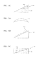
FIGS. 5A through 5E illustrate cross-sectional views of other examples of the optical pathlength control element 136 having different shapes. InFIGS. 1 through 4C , the cross-section of the optical pathlength control element 136 has a wedge shape. However, as shown inFIGS. 5A through 5E , the cross-section of the optical pathlength control element 136 may have different shapes. - Referring to
FIG. 5A , the upper and lower surfaces of the optical pathlength control element 136 have a meniscus shape. Alternatively, although not illustrated inFIG. 5A , only one of the upper and lower surfaces of the optical pathlength control element 136 may have a meniscus shape. - Referring to
FIG. 5B , the upper surface of the optical pathlength control element 136 hasprotrusions 136c. - Referring to
FIG. 5C , the cross-section of the optical pathlength control element 136 has a rectangular formed by two wedge-shapedlayers - Referring to
FIG. 5D , the cross-section of the optical pathlength control element 136 has a rectangular shape, and a refractive index of the optical pathlength control element 136 gradually changes in a direction parallel to the upper and lower surfaces of the optical pathlength control element 136 as indicated by the gradually increasing shades of gray indicating different refractive indexes. InFIG. 5D , the different shades of gray indicate different refractive indexes. The refractive index may change in discrete steps as illustrated inFIG. 5D , or may change continuously. - Referring to
FIG. 5E , the cross-section of the optical pathlength control element 136 has a stair shape. - By using various shapes for the cross-section of the optical path
length control element 136 as described above, non-linear characteristics that may be generated while performing optical path length modulation in an optical probe including the optical pathlength control element 136 may be corrected. In addition, a modulation degree of the optical path length modulation may be changed by adjusting an angle between the inclined plane of the optical pathlength control element 136 and the base plane thereof, the refractive index of the material of the optical pathlength control element 136, the position of the axis ofrotation 134a of thegalvano scanner 134, or a curvature of the reflective surface of thegalvano scanner 134. -
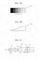
FIG. 6 illustrates an internal configuration of an example of an optical probe including apiezoelectric actuator 135. The optical probe illustrated inFIG. 6 changes the direction of a measurement light using thepiezoelectric actuator 135, rather than thegalvano scanner 134 used in theoptical probe 130 illustrated inFIG. 1 . In greater detail, if an electrical signal is applied topiezoelectric elements 135a disposed in the upper portion and the lower portion of thepiezoelectric actuator 135, thepiezoelectric elements 135a are bent upward or downward, and a supportinglayer 135b of thepiezoelectric actuator 135 that supports thepiezoelectric elements 135a is also bent upward or downward as thepiezoelectric elements 135a are bent upward or downward. The supportinglayer 135b includes anoptical fiber 135c through which the measurement light is transmitted, and a direction of the measurement light that is output from theoptical fiber 135c is changed upward or downward since theoptical fiber 135c is bent upward or downward together with the supportinglayer 135b. The measurement light of different directions that is output from theoptical fiber 135c is collimated by acollimator lens 139, and then sequentially passes through an optical pathlength control element 136 and alens 138, and is irradiated onto a subject (not illustrated inFIG. 6 ). - In the optical probe of
FIG. 6 , optical path length modulation by rotating a galvano scanner about its axis of rotation like thegalvano scanner 134 in theoptical probe 130 illustrated inFIG. 1 is impossible because such a galvano scanner is not used in the optical probe inFIG. 6 . However, by disposing the optical pathlength control element 136 in a path of the measurement light of different directions that is output from theoptical fiber 135c as illustrated inFIG. 6 , the optical path length modulation described above may be performed. The optical pathlength control element 136 inFIG. 6 may have any of the various forms illustrated inFIGS. 4A through 5E . Accordingly, by using thepiezoelectric actuator 135 and the optical pathlength control element 136, a full range OCT apparatus may be implemented using an optical probe in which moving the axis of rotation of a galvano scanner is impossible. - Optical path length modulation for performing phase modulation may also be performed by changing a diameter of measurement as will be described in greater detail below.
-
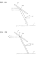
FIG. 7A illustrates an example of a path through which measurement light travels in an optical probe, andFIG. 7B illustrates an example of a path through which response light, i.e., reflection light, travels in an optical probe. - Referring to
FIG. 7A , the measurement light is reflected from thegalvano scanner 134 in a first direction determined by a first rotary position of thegalvano scanner 134 about the axis ofrotation 134a, and the measurement light of the first direction is irradiated onto the subject 10. In this case, the optical pathlength control element 136 is not located in a path of the measurement light. Accordingly, the measurement light is irradiated onto the subject 10 without being influenced by the optical pathlength control element 136. - Referring to
FIG. 7B , reflection light produced by the measurement light reflecting from the subject 10 is reflected from thegalvano scanner 134 without being influenced by the optical pathlength control element 136, and then travels to the outside of the optical probe. -
FIG. 8A illustrates another example of a path through which measurement light travels in an optical probe, andFIG. 8B illustrates another example of a path through which response light, i.e., reflection light, travels in an optical probe. - Referring to
FIG. 8A , thegalvano scanner 134 has rotated counterclockwise about the axis ofrotation 134a compared toFIG. 7A to a second rotary position about the axis ofrotation 134a, and accordingly a direction of the measurement light reflected by thegalvano scanner 134 has moved to the right compared to the direction of the measurement light inFIG. 7A . The measurement light is reflected from thegalvano scanner 134 in a second direction different from the first direction of the measurement light inFIG. 7A , and the measurement light of the second direction is irradiated onto the subject 10. In this case, the optical pathlength control element 136 is located in a path of the measurement light. Accordingly, a portion of the measurement light of the second direction is refracted or blocked by the optical pathlength control element 136, and thus deviates from the second direction, and only a remaining portion of the measurement light continues traveling in the second direction and is irradiated onto the subject 10. That is, the diameter of the measurement light that reaches the subject 10 is reduced compared toFIG. 7A . The optical pathlength control element 136 may be made in various shapes of one material having a constant refractive index or two or more materials having different refractive indexes. Alternatively, the optical pathlength control element 136 may be made of a material that blocks light. - Referring to
FIG. 8B , reflection light produced by the measurement light reflecting from the subject 10 is reflected from thegalvano scanner 134, and then travels to the outside of the optical probe. In this case, the diameter of the reflection light illustrated inFIG. 8B is also reduced compared toFIG. 7B due to the optical pathlength control element 136 refracting or blocking a portion of the measurement light inFIG. 8A . - Accordingly, as described above, the optical path
length control element 136 changes the diameters of the measurement light and the reflection light, which substantially changes the length of an optical path. The reason that the changes in the diameters of the measurement light and the reflection light change the length of the optical path will now be described in detail with reference toFIGS. 7B and8B . - Comparing a
central point 701 of a diameter of the reflection light on thegalvano scanner 134 inFIG. 7B with acentral point 801 of a diameter of the reflection light on thegalvano scanner 134 inFIG. 8B , the position of thecentral point 701 and the position of thecentral point 801 are different from each other. That is, as the diameter of the reflection light on thegalvano scanner 134 changes, the position of the central point of the diameter of the reflection light on thegalvano scanner 134 changes. Since a distance that light travels is substantially a distance that the central point of the diameter of the light travels, optical path lengths of the measurement light and the reflection light illustrated inFIG. 7B are different from the optical path lengths of the measurement light and the reflection light illustrated inFIG. 8B . Accordingly, optical path lengths of the measurement light and the reflection light may be changed by changing the diameters of the measurement light and the reflection light using the optical pathlength control element 136 as described above. - A specific method of performing optical path length modulation to perform phase modulation by changing the diameter of measurement light will now be described.
-
FIG. 9 illustrates another example of a path through which measurement light travels in an optical probe. Referring toFIG. 9 , the diameter of measurement light of a first direction is r1, the diameter of measurement light of a second direction is r2, and the diameter of measurement light of an N-th direction is rN. The diameters are changed using the optical pathlength control element 136 as described above with reference toFIGS. 7A through 8B . If the diameter of a measurement light of an i-th direction is ri (where i is 1, 2, ... , or N), a difference between diameters of two measurement lights of adjacent directions (that is, a measurement light of an i+1-th direction and a measurement light of an i-th direction) may be expressed by the following Equation 6.
- If Δr of Equation 6 is

- Another optical probe may include a lens having a modified shape that simultaneously performs a function of a lens and a function of an optical path length control element. Examples of such an optical probe will be described in greater detail below with reference to
FIGS. 10A and 10B . -
FIGS. 10A and 10B illustrate internal configurations of other examples of optical probes. ComparingFIGS. 10A and 10B withFIGS. 3A through 3C , the optical probes ofFIGS. 3A through 3C include the optical pathlength control element 136 and thelens 138 as separate elements, whereas the optical probes ofFIGS. 10A and 10B do not include the optical pathlength control element 136, but include only thelens 138. In this case, one surface of thelens 138 ofFIGS. 10A and 10B is formed as an inclined plane like the inclined plane of the optical pathlength control element 136 ofFIGS. 3A to 3C , and accordingly the shape of thelens 138 ofFIGS. 10A and 10B is similar to a shape obtained by combining the optical pathlength control element 136 ofFIGS. 3A to 3C with an upper or lower surface of thelens 138 ofFIGS. 3A through 3C . That is, thelens 138 ofFIGS. 10A and 10B simultaneously performs the functions of the optical pathlength control element 136 and thelens 138 ofFIGS. 3A through 3C . Thelens 138 ofFIGS. 10A and 10B enables a configuration of an optical probe to be simplified by providing the function changing an optical path length by modifying a lens. - While this disclosure includes specific examples, it will be apparent to one of ordinary skill in the art that various changes in form and details may be made in these examples without departing from the scope of the claims. The examples described herein are to be considered in a descriptive sense only, and not for purposes of limitation. Descriptions of features or aspects in each example are to be considered as being applicable to similar features or aspects in other examples. Suitable results may be achieved if the described techniques are performed in a different order, and/or if components in a described system, architecture, device, or circuit are combined in a different manner and/or replaced or supplemented by other components or their equivalents. Therefore, the scope of the disclosure is defined not by the detailed description, but by the claims, and all variations within the scope of the claims are to be construed as being included in the disclosure.
Claims (15)
- An optical probe for irradiating light onto a subject, the optical probe comprising:an optical path control unit configured to receive light from outside the optical probe, and change a path of the light within the optical probe;an optical path length control element configured to receive the light having the changed path from the optical path control unit, and change an optical path length of the light as the optical path control unit changes the path of the light; andan optical output unit configured to receive the light having the changed optical path length from the optical path length control element, and output the light.
- The optical probe of claim 1, wherein the optical output unit is further configured to irradiate the light output from the optical output unit onto a subject;
the optical path control unit is further configured to change the path of the light to repeatedly move a point where the light output from the optical output unit is irradiated onto the subject by a predetermined distance in a predetermined direction; and
the optical path length control element is further configured to uniformly change the optical path length each time the point where the light is irradiated onto the subject moves. - The optical probe of claim 1 or 2, wherein the optical path length control element is further configured to transmit the light having the changed path through the optical path length control element, and change the optical path length of the light according to a point of the optical path length control element through which the light passes.
- The optical probe of claim 3, wherein the optical path length control element has a nonuniform thickness, and comprises a material having a uniform refractive index.
- The optical probe of claim 4, wherein a cross-section of the optical path length control element has a wedge shape.
- The optical probe of claim 4, wherein at least one surface of the optical path length control element has a meniscus shape.
- The optical probe of one of claims 3 to 5, wherein the optical path length control element comprises at least two materials having different refractive indexes.
- The optical probe of claim 3, wherein the optical path length control element comprises protrusions on a surface of the optical path length control element.
- The optical probe of one of claims 1 to 8, wherein the optical path length control element is further configured to change the optical path length of the light having the changed path by changing a diameter of the light having the changed path by refracting or blocking a portion of the light having the changed path.
- The optical probe of claim 9, wherein the optical path length control element is further configured to change the optical path length of the light have the changed path by changing the diameter of the light having the changed path according to the changed path.
- The optical probe of one of claims 1 to 10, wherein the optical path control unit comprises a mirror configured to rotate by a predetermined degree of rotation about a fixed axis of rotation each time the optical path control unit changes the path of the light.
- An optical coherence tomography (OCT) apparatus for scanning a subject by irradiating light onto the subject, the apparatus comprising:a light generator configured to generate light;a light coupler configured to split the generated light into a measurement light and a reference light, transmit the measurement light to an optical probe, and receive a response light from the optical probe, the response light being produced by the measurement light reflecting from the subject;a detector configured to detect an interference signal generated by interference between the response signal and the reference signal; andan image signal processor configured to generate a tomographic image of the subject from the detected interference signal;wherein the optical probe is an optical probe according to one of claims 1 to 11 and wherein:the optical path control unit is configured to receive the measurement light from the light coupler, and change a path of the measurement light within the optical probe;the optical path length control element is configured to receive the measurement light having the changed path from the optical path control unit, and change an optical path length of the measurement light as the optical path control unit changes the path of the measurement light; andthe optical output unit is configured to receive the measurement light having the changed optical path length from the optical path length control element, and output the measurement light.
- The apparatus of claim 12, wherein the optical output unit is further configured to irradiate the measurement light output from the optical output unit onto the subject;
the optical path control unit is further configured to change the path of the measurement light to repeatedly move a point where the measurement light output from the optical output unit is irradiated onto the subject by a predetermined distance in a predetermined direction; and
the optical path length control element is further configured to uniformly change the optical path length each time the point where the measurement light is irradiated onto the subject moves. - The apparatus of claim 12 or 13, wherein the optical path length control element is further configured to transmit the measurement light having the changed path through the optical path length control element, and change the optical path length of the measurement according to a point of the optical path length control element through which the measurement light passes.
- The apparatus of one of claims 12 to 14, wherein the optical path length control element is further configured to change the optical path length of the measurement light having the changed path by changing a diameter of the measurement light having the changed patch by blocking a portion of the measurement light having the changed path.
Applications Claiming Priority (2)
| Application Number | Priority Date | Filing Date | Title |
|---|---|---|---|
| KR20120002469 | 2012-01-09 | ||
| KR1020120082564A KR101919012B1 (en) | 2012-01-09 | 2012-07-27 | Optical Probe and Optical Coherence Tomography Apparatus including the same |
Publications (1)
| Publication Number | Publication Date |
|---|---|
| EP2612593A1 true EP2612593A1 (en) | 2013-07-10 |
Family
ID=47627978
Family Applications (1)
| Application Number | Title | Priority Date | Filing Date |
|---|---|---|---|
| EP13150636.2A Withdrawn EP2612593A1 (en) | 2012-01-09 | 2013-01-09 | Optical probe and optical coherence tomography apparatus including the same |
Country Status (3)
| Country | Link |
|---|---|
| US (1) | US10048055B2 (en) |
| EP (1) | EP2612593A1 (en) |
| CN (1) | CN103251387A (en) |
Families Citing this family (7)
| Publication number | Priority date | Publication date | Assignee | Title |
|---|---|---|---|---|
| CN107923738B (en) * | 2015-05-28 | 2020-06-09 | 柯巴股份公司 | Electronic angle measuring device for measuring the bending angle between the arms of the sheet |
| CN105796044B (en) * | 2016-05-25 | 2017-08-25 | 珠海康弘发展有限公司 | Endoscope and its imaging method |
| WO2019092696A1 (en) | 2017-11-07 | 2019-05-16 | Notal Vision Ltd. | Methods and systems for alignment of ophthalmic imaging devices |
| CN111511268B (en) | 2017-11-07 | 2023-12-26 | 诺达尔视觉有限公司 | Retinal imaging devices and related methods |
| US10595722B1 (en) | 2018-10-03 | 2020-03-24 | Notal Vision Ltd. | Automatic optical path adjustment in home OCT |
| US10653311B1 (en) | 2019-06-12 | 2020-05-19 | Notal Vision Ltd. | Home OCT with automatic focus adjustment |
| CN112067580B (en) * | 2020-10-09 | 2025-11-11 | 台州精奥矩阵科技有限公司 | Fourier near infrared spectrum interferometer and instrument for detecting materials on line |
Citations (7)
| Publication number | Priority date | Publication date | Assignee | Title |
|---|---|---|---|---|
| US3871750A (en) * | 1971-12-13 | 1975-03-18 | Singer Co | Focusing roll and displacement prisms |
| US20050168751A1 (en) * | 1998-09-21 | 2005-08-04 | Olympus Corporation | Optical imaging apparatus |
| US20060165350A1 (en) * | 2002-06-07 | 2006-07-27 | Gelikonov Grigory V | Method for obtaining the image of an object, device for carrying out said method and device for delivering low coherent optical radiation |
| CA2555477A1 (en) * | 2005-10-21 | 2007-04-21 | National Research Council Of Canada | Method and apparatus for scanning optical delay line |
| US20070219437A1 (en) * | 2006-03-17 | 2007-09-20 | Glucolight Corporation | System and method for creating a stable optical interface |
| WO2010041182A1 (en) * | 2008-10-09 | 2010-04-15 | Koninklijke Philips Electronics N.V. | Beam direction controlling device and light-output device |
| US20100202030A1 (en) * | 2009-02-09 | 2010-08-12 | KAIST (Korea Advanced Institute of Science and Technology) | Variable view imaging system with combination of telecentric scanner and double wedge prisms |
Family Cites Families (19)
| Publication number | Priority date | Publication date | Assignee | Title |
|---|---|---|---|---|
| JP2001125009A (en) | 1999-10-28 | 2001-05-11 | Asahi Optical Co Ltd | Endoscope device |
| AU2002357016A1 (en) * | 2001-11-28 | 2003-06-10 | James W. Overbeck | Scanning microscopy, fluorescence detection, and laser beam positioning |
| EP2280258A3 (en) * | 2003-06-06 | 2015-09-02 | The General Hospital Corporation | Process and apparatus for a wavelength tuned light source |
| JP4505807B2 (en) | 2004-08-09 | 2010-07-21 | 国立大学法人 筑波大学 | Multiplexed spectral interferometric optical coherence tomography |
| US7336366B2 (en) | 2005-01-20 | 2008-02-26 | Duke University | Methods and systems for reducing complex conjugate ambiguity in interferometric data |
| WO2006078802A1 (en) * | 2005-01-21 | 2006-07-27 | Massachusetts Institute Of Technology | Methods and apparatus for optical coherence tomography scanning |
| JP2007101250A (en) * | 2005-09-30 | 2007-04-19 | Fujifilm Corp | Optical tomographic imaging method |
| JP2007209536A (en) | 2006-02-09 | 2007-08-23 | Kyocera Corp | Optical imaging device |
| WO2007109127A2 (en) | 2006-03-16 | 2007-09-27 | Duke University | Methods, systems, and computer program products for performng real-time quadrature projection based fourier domain optical coherence tomography |
| GB0624361D0 (en) | 2006-12-06 | 2007-01-17 | Michelson Diagnostics Ltd | Multiple beam source for a multi-beam interferometer and multi-beam interferometer |
| JP5306041B2 (en) * | 2008-05-08 | 2013-10-02 | キヤノン株式会社 | Imaging apparatus and method thereof |
| RU2431876C2 (en) | 2008-12-24 | 2011-10-20 | Корпорация "САМСУНГ ЭЛЕКТРОНИКС Ко., Лтд." | Three-dimensional image camera with photomodulator |
| JP5054072B2 (en) * | 2009-07-28 | 2012-10-24 | キヤノン株式会社 | Optical tomographic imaging system |
| KR101078190B1 (en) | 2009-10-15 | 2011-11-01 | 이큐메드 주식회사 | Wavelength detector and optical coherence topography having the same |
| JP2011104266A (en) | 2009-11-20 | 2011-06-02 | Hoya Corp | Oct (optical coherence tomography) probe and oct system |
| JP5467343B2 (en) | 2009-12-02 | 2014-04-09 | 学校法人北里研究所 | Optical coherence tomography apparatus and tomographic imaging method |
| US8363225B2 (en) | 2010-01-14 | 2013-01-29 | University Of Rochester | Optical coherence tomography (OCT) apparatus, methods, and applications |
| JP4916573B2 (en) * | 2010-01-28 | 2012-04-11 | パナソニック株式会社 | Optical interference measurement method and optical interference measurement apparatus |
| JP5394317B2 (en) * | 2010-05-17 | 2014-01-22 | 富士フイルム株式会社 | Rotationally symmetric aspherical shape measuring device |
-
2013
- 2013-01-09 CN CN2013100082717A patent/CN103251387A/en active Pending
- 2013-01-09 US US13/737,370 patent/US10048055B2/en not_active Expired - Fee Related
- 2013-01-09 EP EP13150636.2A patent/EP2612593A1/en not_active Withdrawn
Patent Citations (7)
| Publication number | Priority date | Publication date | Assignee | Title |
|---|---|---|---|---|
| US3871750A (en) * | 1971-12-13 | 1975-03-18 | Singer Co | Focusing roll and displacement prisms |
| US20050168751A1 (en) * | 1998-09-21 | 2005-08-04 | Olympus Corporation | Optical imaging apparatus |
| US20060165350A1 (en) * | 2002-06-07 | 2006-07-27 | Gelikonov Grigory V | Method for obtaining the image of an object, device for carrying out said method and device for delivering low coherent optical radiation |
| CA2555477A1 (en) * | 2005-10-21 | 2007-04-21 | National Research Council Of Canada | Method and apparatus for scanning optical delay line |
| US20070219437A1 (en) * | 2006-03-17 | 2007-09-20 | Glucolight Corporation | System and method for creating a stable optical interface |
| WO2010041182A1 (en) * | 2008-10-09 | 2010-04-15 | Koninklijke Philips Electronics N.V. | Beam direction controlling device and light-output device |
| US20100202030A1 (en) * | 2009-02-09 | 2010-08-12 | KAIST (Korea Advanced Institute of Science and Technology) | Variable view imaging system with combination of telecentric scanner and double wedge prisms |
Also Published As
| Publication number | Publication date |
|---|---|
| US10048055B2 (en) | 2018-08-14 |
| CN103251387A (en) | 2013-08-21 |
| US20130176572A1 (en) | 2013-07-11 |
Similar Documents
| Publication | Publication Date | Title |
|---|---|---|
| US10048055B2 (en) | Optical probe and optical coherence tomography apparatus including the same | |
| CN101617215B (en) | System and method for optical coherence tomography | |
| CN101617196B (en) | Systems and methods for optical coherence tomography and methods for calibrating such systems | |
| US11835707B2 (en) | Scanning optical imaging device | |
| US8340455B2 (en) | Systems and methods for performing Gabor-domain optical coherence microscopy | |
| CN101517397B (en) | Information acquisition device and information acquisition method for acquiring object information by using terahertz waves | |
| CN101617217B (en) | System for optical coherence tomography | |
| US20110267663A1 (en) | Holographic image projection method and holographic image projection system | |
| WO2006004743A2 (en) | Optical fiber scanner for performing multimodal optical imaging | |
| JP2011235084A (en) | Model eye, adjustment method of optical tomographic imaging apparatus and evaluation method | |
| US20120194661A1 (en) | Endscopic spectral domain optical coherence tomography system based on optical coherent fiber bundle | |
| EP3884852B1 (en) | Apparatus and method for optical coherence tomography | |
| CN101617195A (en) | The system and method that is used for optical coherence tomography | |
| JP2016017915A (en) | Optical coherence tomography device | |
| US9880381B2 (en) | Varifocal lens, optical scanning probe including the varifocal lens, and medical apparatus including the optical scanning probe | |
| KR101919012B1 (en) | Optical Probe and Optical Coherence Tomography Apparatus including the same | |
| EP2634558A2 (en) | Shape measurement device and shape measurement method | |
| Lengenfelder et al. | Contact‐free endoscopic photoacoustic sensing using speckle analysis | |
| US20150126857A1 (en) | Optical probe and medical imaging apparatus including the same | |
| EP4498065A1 (en) | Optical coherence tomography apparatus, optical coherence tomography system, optical coherence tomography method and inspection method | |
| JP4755934B2 (en) | Tunable laser device and optical tomographic imaging apparatus | |
| Samadi | DESIGN OF A LINE FIELD OPTICAL COHERENCE TOMOGRAPHY FOR IMAGING APPLICATIONS | |
| JP2013162079A (en) | Wavelength sweeping light source | |
| Hiratsuka et al. | Optical Coherence Tomography System based on Synthesis of Optica Coherence Function with a Wavelength-Scanning Laser Source | |
| Kamal | Reflective optics-based line-scanning spectral domain optical coherence tomography system |
Legal Events
| Date | Code | Title | Description |
|---|---|---|---|
| PUAI | Public reference made under article 153(3) epc to a published international application that has entered the european phase |
Free format text: ORIGINAL CODE: 0009012 |
|
| AK | Designated contracting states |
Kind code of ref document: A1 Designated state(s): AL AT BE BG CH CY CZ DE DK EE ES FI FR GB GR HR HU IE IS IT LI LT LU LV MC MK MT NL NO PL PT RO RS SE SI SK SM TR |
|
| AX | Request for extension of the european patent |
Extension state: BA ME |
|
| 17P | Request for examination filed |
Effective date: 20140110 |
|
| RBV | Designated contracting states (corrected) |
Designated state(s): AL AT BE BG CH CY CZ DE DK EE ES FI FR GB GR HR HU IE IS IT LI LT LU LV MC MK MT NL NO PL PT RO RS SE SI SK SM TR |
|
| STAA | Information on the status of an ep patent application or granted ep patent |
Free format text: STATUS: THE APPLICATION HAS BEEN WITHDRAWN |
|
| 18W | Application withdrawn |
Effective date: 20150126 |