EP2611988B1 - Multi-function isolation tool and method of use - Google Patents
Multi-function isolation tool and method of use Download PDFInfo
- Publication number
- EP2611988B1 EP2611988B1 EP11820954.3A EP11820954A EP2611988B1 EP 2611988 B1 EP2611988 B1 EP 2611988B1 EP 11820954 A EP11820954 A EP 11820954A EP 2611988 B1 EP2611988 B1 EP 2611988B1
- Authority
- EP
- European Patent Office
- Prior art keywords
- wellbore
- tubing string
- fluid
- valve housing
- lower sealing
- Prior art date
- Legal status (The legal status is an assumption and is not a legal conclusion. Google has not performed a legal analysis and makes no representation as to the accuracy of the status listed.)
- Active
Links
- 238000000034 method Methods 0.000 title claims description 23
- 238000002955 isolation Methods 0.000 title description 11
- 239000012530 fluid Substances 0.000 claims description 101
- 238000011282 treatment Methods 0.000 claims description 54
- 238000007789 sealing Methods 0.000 claims description 49
- 238000004873 anchoring Methods 0.000 claims description 15
- 239000004576 sand Substances 0.000 description 13
- 239000007787 solid Substances 0.000 description 10
- 230000007246 mechanism Effects 0.000 description 7
- 230000015572 biosynthetic process Effects 0.000 description 6
- 239000004568 cement Substances 0.000 description 3
- 239000007789 gas Substances 0.000 description 3
- 238000005086 pumping Methods 0.000 description 3
- 239000002002 slurry Substances 0.000 description 3
- 230000000087 stabilizing effect Effects 0.000 description 3
- IJGRMHOSHXDMSA-UHFFFAOYSA-N Atomic nitrogen Chemical compound N#N IJGRMHOSHXDMSA-UHFFFAOYSA-N 0.000 description 2
- CURLTUGMZLYLDI-UHFFFAOYSA-N Carbon dioxide Chemical compound O=C=O CURLTUGMZLYLDI-UHFFFAOYSA-N 0.000 description 2
- ATUOYWHBWRKTHZ-UHFFFAOYSA-N Propane Chemical compound CCC ATUOYWHBWRKTHZ-UHFFFAOYSA-N 0.000 description 2
- 230000000712 assembly Effects 0.000 description 2
- 238000000429 assembly Methods 0.000 description 2
- 238000004891 communication Methods 0.000 description 2
- 230000007257 malfunction Effects 0.000 description 2
- VNWKTOKETHGBQD-UHFFFAOYSA-N methane Chemical compound C VNWKTOKETHGBQD-UHFFFAOYSA-N 0.000 description 2
- 230000004048 modification Effects 0.000 description 2
- 238000012986 modification Methods 0.000 description 2
- 230000002028 premature Effects 0.000 description 2
- 239000000725 suspension Substances 0.000 description 2
- XLYOFNOQVPJJNP-UHFFFAOYSA-N water Substances O XLYOFNOQVPJJNP-UHFFFAOYSA-N 0.000 description 2
- 239000004215 Carbon black (E152) Substances 0.000 description 1
- 229910000831 Steel Inorganic materials 0.000 description 1
- 239000003082 abrasive agent Substances 0.000 description 1
- 230000004308 accommodation Effects 0.000 description 1
- 238000009825 accumulation Methods 0.000 description 1
- 230000004075 alteration Effects 0.000 description 1
- 230000002457 bidirectional effect Effects 0.000 description 1
- 229910002092 carbon dioxide Inorganic materials 0.000 description 1
- 239000001569 carbon dioxide Substances 0.000 description 1
- 239000003245 coal Substances 0.000 description 1
- 230000001351 cycling effect Effects 0.000 description 1
- 230000001934 delay Effects 0.000 description 1
- 230000001419 dependent effect Effects 0.000 description 1
- 238000010586 diagram Methods 0.000 description 1
- 230000009977 dual effect Effects 0.000 description 1
- 229930195733 hydrocarbon Natural products 0.000 description 1
- 150000002430 hydrocarbons Chemical class 0.000 description 1
- 238000010348 incorporation Methods 0.000 description 1
- 230000002401 inhibitory effect Effects 0.000 description 1
- 230000000977 initiatory effect Effects 0.000 description 1
- 238000002347 injection Methods 0.000 description 1
- 239000007924 injection Substances 0.000 description 1
- 239000000203 mixture Substances 0.000 description 1
- 229910052757 nitrogen Inorganic materials 0.000 description 1
- 239000003921 oil Substances 0.000 description 1
- 239000001294 propane Substances 0.000 description 1
- 230000004044 response Effects 0.000 description 1
- 230000002441 reversible effect Effects 0.000 description 1
- 238000012552 review Methods 0.000 description 1
- 239000010959 steel Substances 0.000 description 1
- 238000012360 testing method Methods 0.000 description 1
Images


Classifications
-
- E—FIXED CONSTRUCTIONS
- E21—EARTH OR ROCK DRILLING; MINING
- E21B—EARTH OR ROCK DRILLING; OBTAINING OIL, GAS, WATER, SOLUBLE OR MELTABLE MATERIALS OR A SLURRY OF MINERALS FROM WELLS
- E21B23/00—Apparatus for displacing, setting, locking, releasing or removing tools, packers or the like in boreholes or wells
- E21B23/004—Indexing systems for guiding relative movement between telescoping parts of downhole tools
- E21B23/006—"J-slot" systems, i.e. lug and slot indexing mechanisms
-
- E—FIXED CONSTRUCTIONS
- E21—EARTH OR ROCK DRILLING; MINING
- E21B—EARTH OR ROCK DRILLING; OBTAINING OIL, GAS, WATER, SOLUBLE OR MELTABLE MATERIALS OR A SLURRY OF MINERALS FROM WELLS
- E21B33/00—Sealing or packing boreholes or wells
- E21B33/10—Sealing or packing boreholes or wells in the borehole
- E21B33/12—Packers; Plugs
- E21B33/126—Packers; Plugs with fluid-pressure-operated elastic cup or skirt
Definitions
- Tools for use downhole in the completion of a wellbore are generally well known.
- perforation devices are commonly deployed downhole on wireline, cable, or on tubing string
- sealing devices such as bridge plugs and straddle packers are commonly used to isolate portions of the wellbore during fluid treatment.
- bridge plugs and straddle packers are commonly used to isolate portions of the wellbore during fluid treatment.
- Any one or more steps may be repeated within a single wellbore as desired, without removing the tool assembly from the wellbore.
- the terms “above/below” and “upper/lower” are used for ease of understanding, and are generally intended to mean the uphole and downhole direction from surface. However, these terms may be imprecise in certain embodiments depending on the configuration of the wellbore. For example, in a horizontal wellbore one device may not be above another, but instead will be closer (uphole, above) or further (downhole, below) from the point of entry into the wellbore. Likewise, the term “surface” is intended to mean the point of entry into the wellbore, that is, the work floor where the assembly is inserted into the wellbore.
- the presently described assembly may be deployed within a wellbore on tubing string wireline, cable, or by other suitable suspension or carriage.
- tubing string such as coiled tubing.
- tubulars for example threaded pipe
- suspension systems wireline, cable, etc.
- the anchor device 41 and actuator assembly 42 shown in the Figures was created from a mechanical-set compressible packer assembly. That is, the packer was modified to replace the compressible packer element with a non-compressible steel cone 45 of appropriate size to engage the slips 41.
- the fingers of mechanical casing collar locator 44 provide sufficient drag resistance for manipulation of the auto J mechanism of the actuator assembly 42 by application of force to the tubing string.
- the pin 73 is driven towards its downward-most pin stop 79a in the J profile, the cone 45 is driven against the slips, forcing them outward against the casing, acting as an anchor within the wellbore.
- the tool assembly is run into the wellbore with pin 73 in the J-profile at the running in position 79.
- the anchor is held in a position that does not allow the mechanical slips of the anchor to engage the casing. Accordingly, the drag of the mechanical casing collar locator and drag pads on the slips is overcome by application of weight to the tubing string, sliding the assembly downhole to a desired treatment position.
- the bypass plug would be sealed within the anchor mandrel as a result of the downward pressure on the pull tube and the resistance by the collar locator. Accordingly, the bypass is typically closed while running in hole.
- Fluid jetted from the nozzles will perforate or erode the casing and, upon continued fluid application, may pass down the wellbore and exit the wellbore, for example passing into a formation through perforations, open hole, or other mechanically placed openings in the wellbore.
- the fluid jetted from nozzles 81 will be abrasive fluid, as generally used in sand jet perforating techniques known in the prior art. It should be noted that in the present methods, the tool assembly is anchored during jetting by the set cup seals, and as a result, focussed perforations are jetted in the casing. This is in contrast with typical prior art methods that do not allow anchoring of the jetting assembly during abrasive perforation methods, and typically create slots or otherwise broad perforations in the casing due to movement of the device during jetting.
- fluid delivery is typically terminated and the pressure within the tubing string and straddled interval is dissipated.
- the tool may then be moved to initiate a further perforation, or a treatment operation.
- the anchor is set by applying a pulling force to the tubing string (and thereby to the pull tube) to cycle the anchor to release position 79b.
- the bypass valve is therefore opened during this pulling force, as the mechanical threshold force to operate the bypass is less than that required to cycle the pin within the auto J profile.
- a further downhole force applied to the tubing string will close the bypass valve again, and further, will drive the pin 73 towards anchor set position 79a, lowering the modified packer element 45 until it engages the mechanical slips 41, driving them outward against the casing.
- the upper cups 20 are slidable with respect to the lower cups 30, as shown in Figures 1 and 5 .
- an uphole force may still be applied to the tubing string to unseat the anchor due to the slidable upper seal assembly. That is, when high pressure fluid is first delivered through the frac ports, the upper cup seal will slide uphole prior to sealing against the casing. Accordingly, following treatment, if the upper cups fail to unset or should excessive debris be present above the upper cup seal, a pulling force applied to the tubing string will slide the upper cups down the tool to their lowermost position. This small amount of play in the position of the upper cup seals minimizes the risk of debris-related failure or of the tool.
- abrasive fluid is delivered to the assembly down the tubing string while the fluid bypass is open.
- the abrasive fluid will simultaneously be delivered to the wellbore via the frac ports, setting the upper and lower cup seals, and to a minimal extent through the jet nozzles.
- a wellbore may contain existing perforations that require fracturing or other fluid treatment.
- additional perforations may also be required.
- the presently described completion tool provides the versatility to operate as a straddle isolation and treatment tool, and as a sand jet perforation device. That is, when the bypass valve is closed, the straddle isolation and treatment function is effectively selected. Should problems arise in the treatment of a particular zone, an additional perforation can be created within the zone with minimal time and cost simply by adjusting the position of the tool as appropriate, opening the bypass valve, and delivering abrasive perforation fluid to the tubing string.
Landscapes
- Geology (AREA)
- Life Sciences & Earth Sciences (AREA)
- Engineering & Computer Science (AREA)
- Mining & Mineral Resources (AREA)
- Environmental & Geological Engineering (AREA)
- Fluid Mechanics (AREA)
- Physics & Mathematics (AREA)
- General Life Sciences & Earth Sciences (AREA)
- Geochemistry & Mineralogy (AREA)
- Branch Pipes, Bends, And The Like (AREA)
- Pipe Accessories (AREA)
- Valve Housings (AREA)
- Earth Drilling (AREA)
- Quick-Acting Or Multi-Walled Pipe Joints (AREA)
- Valves And Accessory Devices For Braking Systems (AREA)
Description
- The present invention relates generally to oil and gas well completion. More particularly, the present invention relates to a tool string for use in perforating, isolating, and fracturing multiple intervals of a gas, oil, or coal bed methane wellbore in a single trip downhole.
- Tools for use downhole in the completion of a wellbore are generally well known. For example, perforation devices are commonly deployed downhole on wireline, cable, or on tubing string, and sealing devices such as bridge plugs and straddle packers are commonly used to isolate portions of the wellbore during fluid treatment. As such, tools are exposed to varying conditions during use, and improvements have evolved over time to address problems typically encountered downhole.
- The Applicants have previously described a tool and method for use in the perforation and treatment of multiple wellbore intervals. That tool included a jet perforation device and sealing assembly, with an equalization valve for controlling fluid flow through and about the assembly. Fluid treatment is applied down the wellbore annulus to treat the uppermost perforated zone.
- When multiple pre-existing perforations are to be treated, application of the treatment fluid down the welbore annulus is not desirable, as perforations cannot be treated selectively by this method. Typically, an isolation device is required. Cup seals are known for use in straddle tools and other isolation tools, but are not well suited for applications requiring repeated use in a single run downhole due to the risk of wear and failure should the tool assembly slide within the wellbore while the seals are set. This risk is greater in applications where sand or other debris is present downhole, as the cup seals may fail to fully seal against the casing in the presence of sand or other solids, leading to sliding of the seals and premature wear.
- Use of any sealing device in the presence of significant amounts of sand or other solids increases the risk of tool malfunction. Further, the tool may become stuck downhole should a solids blockage occur during treatment, or when the formation expels solids upon release of hydraulic pressure in the wellbore annulus when treatment is complete. Typical completion assemblies have many moving components to provide actuation for various downhole functions, and the presence of sand or other solids within these actuation mechanisms would risk jamming these mechanisms, potentially causing a malfunction or permanent damage to the tool or well. Correcting such a situation is costly, and poses significant delays in the completion of the well. Accordingly, well operators, fracturing companies, and tool suppliers/service providers are typically very cautious in their selection of fluids and tools for use in completion operations.
-
US 2004/0163811 A1 discloses a formation treatment tool assembly conveyed within a well casing by a tubing string. It has a housing defining treatment fluid supply and discharge passages and a fluid injection port through which treatment fluid is directed from the supply passage into a packer isolated casing interval. It has a fluid inlet port permitting flow from the isolated casing interval to the fluid discharge passage. There are spaced straddle packer elements capable of establishing sealing engagement with the well casing and which define an isolated casing interval. A dump valve connected with the tool housing can be opened to permit flow of treatment fluid from the isolated casing interval through the treatment fluid discharge passage. A particular isolation valve can be closed to isolate the tubing string from casing or formation pressure and permit tool conveyance. -
US 5,186,258 discloses a well tool having an anchor device, straddle packers above and below a port and an internal valve which are operated by longitudinal motion in an inflatable packer device. The anchor has a hydraulic operated plug. The tool can be attached to a string of tubing and filled with cement slurry. Downward motion is used to anchor the tool in a profile groove in an inflatable packer. The straddle packers can be set above and below an access port on the inflatable packer, and a valve opened to allow cement slurry into the inflatable packer. An upward motion is used to close the valve, unset the straddle packers and release the anchor. A circulation valve is openable by pressure to reverse out cement slurry from the tubing string. -
US 5,954,133 discloses methods of completing wells using wellbore equipment positioning apparatus in which sand control screens and perforating guns can be repositioned without requiring movement of a packer in the wellbore. - In a first aspect, the present invention provides a completion tool for deployment within a wellbore on tubing string, the completion tool comprising: upper and lower sealing members defining a straddle zone between the upper and lower sealing members; one or more treatment ports within the straddle zone, the treatment ports continuous with tubing string to allow fluid delivery to the wellbore from surface; a valve housing mounted beneath the lower sealing member, the valve housing defining a fluid passageway continuous with the tubing string and with the wellbore annulus beneath the lower sealing member to allow pressure equalization therebetween; a bypass plug slidable within the valve housing between an open position in which fluid passage through the housing is permitted, and a sealed position in which fluid passage through the housing is prevented, the plug actuable to open or to seal the passageway upon application of mechanical pressure to the tubing string; and a resettable anchor device operatively mounted beneath the lower sealing member for setting against the casing of a wellbore, the anchor device operable by application of mechanical force to the tubing string.
- The sealing members may be cup seals, inflatable sealing elements, compressible sealing elements, or other mechanical or hydraulically actuated sealing members.
- In one embodiment, the anchor device comprises one or more anchoring slips disposed about a mandrel of the anchor device, and an actuation cone slidable with respect to the mandrel of the anchor device to engage the inwardly biased slips and drive said slips outward to engage the casing, thereby anchoring the tool assembly against the casing. The anchor may be actuated from surface by application of a mechanical force to the tubing string. Where the tubing string is coiled tubing, the mechanical force is an uphole or downhole force.
- In another embodiment, the anchor is actuated from surface by application of mechanical force to the tubing string. For example, the application of mechanical force to the tubing string may drive movement of a pin within an auto J profile, the auto J profile having pin stop positions corresponding to at least two operable positions of the anchor device.
- The anchor device may further comprise a mechanical casing collar locator for providing frictional resistance against which the anchor device may be operated by application of mechanical force to the tubing string from surface.
- In an embodiment, the completion tool further comprises one or more jet perforation nozzles formed within the assembly below the valve housing.
- In accordance with a further aspect of the invention, there is provided a method for treating a wellbore, the method comprising the steps of:
- providing a tool assembly comprising: upper and lower sealing members mounted along a mandrel, defining a straddle zone between the upper and lower sealing members; one or more treatment ports within the straddle zone for delivery of treatment fluid to the wellbore from the tubing string; a valve housing mounted beneath the lower sealing members, the valve housing defining a fluid passageway continuous with the tubing string and with the wellbore annulus beneath the lower sealing member to allow pressure equalization therebetween; a bypass plug slidable within the valve housing between an open position in which fluid passage through the housing is permitted, and a sealed position in which fluid passage through the housing is prevented, the plug actuable to open or to seal the passageway upon application of a mechanical force to the tubing string; and a resettable anchor device operatively mounted beneath the lower sealing member for engaging the casing of a wellbore, the anchor device operable by application of mechanical force to the tubing string; locating the completion tool downhole at a position in which the upper and lower sealing members straddle a casing perforation to be treated;
- sealing the fluid passageway through the valve housing;
- applying mechanical force to the tubing string to set the anchor against the casing; and
- applying treatment fluid to the tubing string to isolate and treat the perforation.
- In an embodiment, the method further comprises the step of unsealing the fluid passageway through the valve housing to equalize hydraulic pressure across the lower sealing member.
- The method may further comprise the step of unsetting the anchor from the casing.
- Any one or more steps may be repeated within a single wellbore as desired, without removing the tool assembly from the wellbore.
- Other aspects and features of the present invention will become apparent to those ordinarily skilled in the art upon review of the following description of specific embodiments of the invention in conjunction with the accompanying figures.
- Embodiments of the present invention will now be described, by way of example only, with reference to the attached Figures, wherein:
-
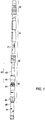
Fig. 1 is a perspective view of a tool assembly in accordance with one embodiment; -
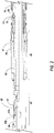
Fig. 2 is a schematic cross sectional view of a portion of a tool assembly having an equalization valve and anchor assembly; -
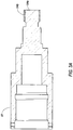
Fig. 3a is a schematic cross sectional view of thebypass plug 51 shown inFigure 2 ; -
Fig. 3b is a schematic cross sectional of theequalization housing 55 shown inFigure 2 ; -
Figure 4 is a diagram of the J-profile used to actuate the tool assembly shown inFigure 2 ; and -
Figure 5 is a schematic cross sectional view of an upper portion of a tool assembly having slidable upper cup seals. - Generally, a downhole assembly, or completion tool, and method are provided for use in fracturing multiple intervals of a wellbore without removing the tool string from the wellbore between intervals. This system may generally be used in vertical, deviated, horizontal, or branched oil and gas wells having cased wellbores.
- In the present description, the terms "above/below" and "upper/lower" are used for ease of understanding, and are generally intended to mean the uphole and downhole direction from surface. However, these terms may be imprecise in certain embodiments depending on the configuration of the wellbore. For example, in a horizontal wellbore one device may not be above another, but instead will be closer (uphole, above) or further (downhole, below) from the point of entry into the wellbore. Likewise, the term "surface" is intended to mean the point of entry into the wellbore, that is, the work floor where the assembly is inserted into the wellbore.
- Jet perforation, as mentioned herein, refers to the technique of delivering abrasive fluid at high velocity so as to erode the wall of a wellbore at a particular location, creating a perforation. Typically, abrasive fluid is jetted from nozzles arranged about a mandrel such that the high rate of flow will jet the abrasive fluid from the nozzles toward the wellbore casing. Sand jetting refers to the practice of using sand as the abrasive agent, in an appropriate carrier fluid. For example, typical carrier fluids for use in sand jetting compositions may include one or more of: water, hydrocarbon-based fluids, propane, carbon dioxide, nitrogen assisted water, and the like.
- The presently described assembly may be deployed within a wellbore on tubing string wireline, cable, or by other suitable suspension or carriage. The embodiments of the assembly depicted in the Figures are shown and described as being deployed on tubing string, such as coiled tubing. However, other types of tubulars (for example threaded pipe) or other suspension systems (wireline, cable, etc.) may be suitable depending on the application.
- Generally, the completion tool may be deployed on tubing string such as jointed pipe, concentric tubing, or coiled tubing. The assembly will typically include upper and lower isolation elements, a fracturing port between the isolation elements, and an anchoring device below the lower isolation element. A jet perforation device may also be present below the lower isolation element.
- An anchoring device is provided, in some embodiments, for stability in setting the tool, and to prevent sliding of the tool assembly within the wellbore during treatment. Further, the anchoring device allows controlled actuation of the equalization valve/plug within the housing by application of mechanical pressure to the tubing string from surface. Suitable anchoring devices may include drag blocks, mechanical slips, packers, and other anchor devices known in the art. Simple mechanical actuation of the anchor is generally preferred to provide adequate control over setting of the anchor, and to minimize failure or debris-related jamming during setting and releasing the anchor. Mechanical actuation of the anchor assembly is loosely coupled to actuation of the bypass valve, allowing coordination between these two slidable mechanisms. The presence of a mechanical casing collar locator, or other device providing some degree of friction against the casing, is helpful in providing resistance against which the anchor and bypass/equalization valve may be mechanically actuated.
- Various sealing devices for use within the tool assembly to isolate the zone of interest are available, including friction cups, inflatable packers, and compressible sealing elements. In the particular embodiments illustrated and discussed herein, friction cups are shown straddling the fracturing/treatment ports of the tool. When a jet perforation device is also present within the tool assembly, these friction cups also act as an anchor for the tool assembly during jet perforation as will be described below.
- While the presently described embodiments employ cup seals to isolate wellbore intervals, and may further incorporate an anchor assembly to secure the position of the tool at each interval prior to fracturing, alternate selections and arrangement of the assembly components may be made in accordance with the degree of variation and experimentation typical in this art field.
- With reference to
Figure 1 , a fracturing ortreatment assembly 10 is provided for delivering fracturing fluid (or other treatment fluid) to a wellbore interval of interest through the tubing string.Double cup assemblies assembly 10 and seal against the casing upon delivery of pressurized treatment fluid to the wellbore interval. Ananchor assembly 40 engages the casing below the isolated interval. Fluid jetting device 80 (when present) may be utilized to deliver high velocity abrasive fluid throughjet nozzles 81 to form perforations in the wellbore when necessary. - The tool string is assembled and deployed downhole on tubing (for example coiled tubing or jointed pipe) to a wellbore interval of interest. The anchor is then set against the casing, and fluid is pumped down the tubing under pressure, exiting the tubing string at
frac ports 11. This results in flaring of the friction cups 20, 30, with the flared cups sealing against the casing. - If fracturing, or other fluid treatment, is desired, the
bypass valve 43 is closed and the friction cups are located about a perforated portion of the wellbore. The closed bypass valve prevents fluid from passing down the tool string to thejet perforation device 80. Accordingly, the fluid delivered to the assembly will exit theports 41 and pressurize the straddled interval, delivering treatment fluid to the zone through the isolated perforations. When treatment is terminated, thebypass valve 43 is pulled open to release pressure from the isolated zone, allowing fluid and debris to flow downhole through the bottom portion of the tool string. Pressure within the tubing string may also be dissipated, if necessary, from surface. Once the pressure within the fractured zone is relieved, the cup seals relax to their running position. The anchor is then unset and the tool string can be moved to the next interval of interest or retrieved from the wellbore. - If perforation of the wellbore is desired, the
bypass valve 43 is open and the friction cups are set across the wellbore above the zone to be perforated. Pumping abrasive fluid down the tubing string will deliver fluid preferentially through thetreatment ports 11 until the friction cups seal against the wellbore. As this interval is unperforated, this interval remains pressurized and thus acts as an anchor, securing the position of the tool assembly within the wellbore. Further fluid delivery will be reach the perforation device and exit atjet nozzles 81, resulting in jetting of abrasive fluid against the casing to perforate the wellbore adjacent the jet nozzles. - As the environment in which the present tool string is used may be sand-laden (due to the formation characteristics, use of abrasive fluids and/or proppant-laden treatment fluids), there is a significant risk that debris may accumulate within the apertures, slots, chambers, and moving parts of the tool during deployment. For example, solids may accumulate over the cups and anchor. Accordingly, debris relief features may be incorporated into the tool, as discussed in copending Canadian application
2,693,676 . - With reference to the assembly shown in
Figure 1 , the upper 20 and lower 30 cup seals generally define the zone to be isolated for fluid treatment. The spacing of these seals is predetermined prior to assembly and may be customized for each run downhole. The upper seals 20 are slidably disposed above the fracturingassembly 10 as shown inFigure 5 . The lower cup seals 30 are assembled between thetreatment ports 11 and theanchor assembly 40. Afluid jetting device 80 may also be assembled below the lower cup seals 30. - The depicted fracturing
assembly 10 also includes a blast joint(s), and a centralizer. Additional tool string components may also be present. Fluid delivery ports/frac ports 11 in the fracturing assembly allow for delivery of fluid to the wellbore from surface. - The
anchor assembly 40 includes ananchor device 41 and actuator assembly (in the present drawings represented by cone element 45), a bypass/equalization valve 43, and acasing collar locator 44. As shown in the Figures, theanchor device 41 may be a set of mechanical slips driven outwardly against the casing. In the embodiment shown in the Figures, the slips are driven outwardly by downward movement of thecone element 45. The bypass assembly and anchor actuator shown inFigure 1 are controlled from surface by applying a mechanical force to the coiled tubing, which drives apin 73 within anauto J profile 74 about theactuator assembly mandrel 60. This is shown best inFigures 2 and4 . - Suitable anchoring devices may include inflatable packers, compressible packers, drag blocks, and other anchoring devices known in the art. For example, known anchoring devices include mechanically set or hydraulically set anchors having cone-driven undirectional slips or bidirectional slips.
- The
anchor device 41 andactuator assembly 42 shown in the Figures was created from a mechanical-set compressible packer assembly. That is, the packer was modified to replace the compressible packer element with anon-compressible steel cone 45 of appropriate size to engage theslips 41. When placed downhole at an appropriate location, the fingers of mechanicalcasing collar locator 44 provide sufficient drag resistance for manipulation of the auto J mechanism of theactuator assembly 42 by application of force to the tubing string. When thepin 73 is driven towards itsdownward-most pin stop 79a in the J profile, thecone 45 is driven against the slips, forcing them outward against the casing, acting as an anchor within the wellbore. When fracturing is complete, or anchoring is otherwise no longer necessary, thecone 45 is removed from engagement with the inwardly-biased slips by manipulation of the pin within the J profile to therelease position 79b, allowing retraction of theslips 41 from the casing. Anchoring of the assembly within the wellbore ensures appropriate placement of fluid treatment and also prevents sliding of the cup seals within the wellbore, which may otherwise lead to premature wear, as is often responsible for the failure of cup seals in other tools. - During jet perforation, the anchor is typically unset and the bypass is open. When fluid pressure is applied the cup seals will engage the casing, and the tool string will remain fixed, stabilizing the jet sub while abrasive fluid is jetted through
nozzles 81. - The bypass assembly is a modified version of the equalization valve described in Applicant's copending Canadian application
2,693,676 . Notably, the bypass provides a central fluid passageway from the tubing to the lower wellbore.Bypass plug 51 is slidable within the assembly upon application of force to the tubing string, to open and close the passageway. Notably, while the states of the bypass and anchor are both dependent on application of force to the tubing string from surface, the bypass plug is actuated initially without any movement of thepin 73 within theJ slot 74. - To initiate isolation and treatment of the wellbore interval of interest, the anchor is set, closing the bypass valve and stabilizing the wellbore. A volume of treatment fluid is delivered through the tubing string under pressure, which will cause the cup seals to set against the casing. Further delivery of fluid will treat the interval as desired. When treatment is complete, pressure from the isolated zone is equalized across the anchor by opening the equalization or
bypass valve 43. As fluid passes from the isolated zone through the bypass valve to equalize the pressure differential across the lower cup seal, the cup seals will unset from the casing. In the event that the upper cup seals do not unset simultaneously with the lower cup seals, or do not unset fully, the position of the tool assembly is maintained by the anchor remaining set against the casing. To unset the anchor, an uphole force is applied to the tubing string, physically driving the pin within the J-slot towardsrelease position 79b. - When the equalization valve is open and the anchor is unset, movement of the tool assembly up or downhole is facilitated as wellbore fluids may circulate through the assembly as well as within the wellbore annulus, limiting hydraulic resistance to running in or out of hole.
- The bypass valve includes a
bypass plug 51 slidable within an equalization valve housing 55 (seeFigures 3a and3b ). Such slidable movement is actuated from surface by pulling or pushing on the tubing, which is anchored to the assembly by amain pull tube 59. The main pull tube is generally cylindrical and provides an open central passageway for fluid communication through the housing from the tubing. Thebypass plug 51 is anchored over thepull tube 59, forming anupper shoulder 51a that limits the extent of travel of thebypass plug 51 within thevalve housing 55. Specifically, an upper lock nut is attached to thevalve housing 55 and seals against the outer surface of thepull tube 59, defining astop 53a for abutment against theupper shoulder 51a of the bypass plug. - The lower end of the
valve housing 55 is anchored overanchor mandrel 60, defining a lowermost limit to which thebypass plug 51 may travel within thevalve housing 55. Thebypass plug 51 is closed at itslower end 54a, and is overlaid with a bondedseal 54b. Thesolid plug end 54a and bondedseal 54b are sized to engage the inner diameter of theanchor mandrel 60, preventing fluid communication between wellbore annulus/tubing string and the lower wellbore when thebypass plug 51 has reached the lower limit of travel. - The engagement of the bonded
seal 54b within themandrel 60 prevents fluid passage, but may be removed to open the mandrel by applying sufficient pull force to the coiled tubing. This pull force is less than the pull force required to unset the anchor due to the slidability of thebypass plug 51 within the housing between themandrel 60 and thepull tube stop 53a. Accordingly, the equalization valve may be opened by application of pulling force to the tubing string while the anchor device remains set against the wellbore casing. This allows equalization of pressure from the isolated zone and unsetting of the cup seals without slippage and damage to the cup seals while pressure is being equalized. - The mechanism for setting and unsetting the anchor involves applying a force (either uphole or downhole) to the coiled tubing, which is translated to pull
tube 59. That is, aJ profile 74 is formed about theassembly mandrel 60.Pin 73 is held in place over the mandrel (within the J-profile), for example by a one-piece or two-piececlutch ring 76. The rotational movement of the J-pin within the J profile is independent of the tubing string so as not to cause torque to build up within the tubing string. The clutch ring and J profile may each have debris relief openings for allowing passage of fluid and solids during sliding of thepin 73 within theJ profile 74. - Various J profiles suitable for actuating downhole devices are known within the art. One
suitable J profile 74 is shown inFigure 4 , having three sequential positions that are repeated about the mandrel.Debris relief apertures 78 may be present at various locations within the J-profile to permit discharge of settled solids as thepin 73 slides within the J profile. TheJ slots 74 are also deeper than would generally be required based on the pin length alone, which further provides accommodation for debris accumulation and relief without inhibiting actuation of the sealing device. - With reference to the J profile shown in
Figure 4 , three pin stop positions are shown, namely an anchor setposition 79a, arelease position 79b, and a running-inposition 79c. Theassembly mandrel 60 is coupled to thepull tube 59, which is slidable with respect to thebottom sub mandrel 50 that holds thepin 73. The mechanicalcasing collar locator 44 generally drags against the casing and provides sufficient resistance to allow thepin 73 to slide within theJ profile 74 as thepull tube 59 is manipulated from surface. - In the embodiment shown in the drawings, it is advantageous that the pull tube actuates both the bypass valve and the J mechanism for the anchor device, at varying forces to allow selective actuation. However, other mechanisms for providing this functionality may now be apparent to those skilled in this art field and are within the scope of the present teaching.
- Components may be duplicated within the assembly, and placed as desired, for example by connecting one or more blast joints within the assembly. This spacing may be used to protect the tool assembly components from abrasive damage downhole, such as when solids are expelled from the perforations following pressurized treatment. For example, the blast joints may be positioned within the assembly to receive the initial abrasive fluid expelled from the perforations as treatment is terminated and the tool is pulled uphole.
- Other methods for treatment of the perforations using the presently described tool string (with or without modification) are possible, using the knowledge and experience typical of operators in this field of art.
- The tool assembly is run into the wellbore with
pin 73 in the J-profile at the running in position 79. At this stop, the anchor is held in a position that does not allow the mechanical slips of the anchor to engage the casing. Accordingly, the drag of the mechanical casing collar locator and drag pads on the slips is overcome by application of weight to the tubing string, sliding the assembly downhole to a desired treatment position. It may be noted that the bypass plug would be sealed within the anchor mandrel as a result of the downward pressure on the pull tube and the resistance by the collar locator. Accordingly, the bypass is typically closed while running in hole. - In order to allow fluid delivered to the tubing string to reach
jet nozzles 81, the bypass valve must be in the open position. It has been noted during use that when fluid is delivered to the bypass valve at high rates, the pressure within the valve typically tends to drive the valve open. That is, a physical force should be applied to hold the valve closed, for example by setting the anchor. Accordingly, when jet perforation is desired, the valve is opened by pulling the tubing string uphole to the perforation location. When fluid delivery is initiated with the bypass valve open, the hydraulic pressure applied to the tubing string (and through frac ports) will cause the cup seals to seal against the casing. If no perforation is present within that interval, the hydraulic pressure within the interval will be maintained between the cups, anchoring the tool assembly within the wellbore. Further pressurized fluid delivered to the tubing will thus not be taken up by the isolated interval, but will be forced/jetted through thenozzles 81. Fluid jetted from the nozzles will perforate or erode the casing and, upon continued fluid application, may pass down the wellbore and exit the wellbore, for example passing into a formation through perforations, open hole, or other mechanically placed openings in the wellbore. Typically, the fluid jetted fromnozzles 81 will be abrasive fluid, as generally used in sand jet perforating techniques known in the prior art. It should be noted that in the present methods, the tool assembly is anchored during jetting by the set cup seals, and as a result, focussed perforations are jetted in the casing. This is in contrast with typical prior art methods that do not allow anchoring of the jetting assembly during abrasive perforation methods, and typically create slots or otherwise broad perforations in the casing due to movement of the device during jetting. - Once jetting is accomplished, fluid delivery is typically terminated and the pressure within the tubing string and straddled interval is dissipated. The tool may then be moved to initiate a further perforation, or a treatment operation.
- The anchor is set by applying a pulling force to the tubing string (and thereby to the pull tube) to cycle the anchor to release
position 79b. The bypass valve is therefore opened during this pulling force, as the mechanical threshold force to operate the bypass is less than that required to cycle the pin within the auto J profile. A further downhole force applied to the tubing string will close the bypass valve again, and further, will drive thepin 73 towards anchor setposition 79a, lowering the modifiedpacker element 45 until it engages themechanical slips 41, driving them outward against the casing. Once the position of the tool assembly downhole is thereby anchored and the bypass closed, a desired volume of fluid is delivered to the formation by pumping fluid through the coiled tubing. When the rate of fluid delivery to the coiled tubing results in high pressure fluid delivery from thefrac ports 11, the hydraulic pressure at the fracturing assembly will exceed a cup seal threshold pressure and the cup seals will become flared outwards, sealing against the casing. The remainder of the wellbore therefore becomes isolated from the treatment interval for the remainder of the treatment application. - Once the treatment is successfully delivered to the isolated interval, the bypass plug may be unset by pulling on the tubing string. This will begin to allow equalization of pressure between the isolated interval and the wellbore beneath the anchor. Pressure within the tubing string may also be relieved at surface. Further pulling force on the tubing string will unset the anchor by sliding of the
pin 73 to theunset position 79b in the J profile. The assembly may then be moved uphole to perforate and treat another interval. - In order to verify proper functioning of the cup seals and equalizing/bypass valve, a pressure test may be conducted in an unperforated wellbore segment prior to use or between treatments. That is, fluid is delivered while annulus pressure is monitored to endure the cups are properly sealing. Fluid flow into the perforations may also be tested.
- Typically, the fluid bypass will be an equalization plug slidable within the valve housing. With reference to the example shown in the Figures, the plug may be moved from a sealed position - in which the
cylindrical plug 54a and bondedseal 54b are engaged within thelower mandrel 60, and an unsealed position in which fluid may pass to and from the interval to the lower wellbore. The plug is operatively attached to pulltube 59, which may be actuated from surface to control the position of theequalization plug 51 within thevalve housing 55. - The
upper cups 20 are slidable with respect to thelower cups 30, as shown inFigures 1 and5 . In the event that debris has built up over the upper cup seal, an uphole force may still be applied to the tubing string to unseat the anchor due to the slidable upper seal assembly. That is, when high pressure fluid is first delivered through the frac ports, the upper cup seal will slide uphole prior to sealing against the casing. Accordingly, following treatment, if the upper cups fail to unset or should excessive debris be present above the upper cup seal, a pulling force applied to the tubing string will slide the upper cups down the tool to their lowermost position. This small amount of play in the position of the upper cup seals minimizes the risk of debris-related failure or of the tool. - A method for deploying and using the above-described tool assembly to perforate and fracture a wellbore is provided. The method typically includes the following steps:
- running a tool string downhole to a predetermined depth, the tool string having a ported mandrel between upper and lower sealing members, a bypass valve below the sealing members, a mechanical casing collar locator below the lower sealing members; and one or more jet perforation nozzles below the bypass valve;
- setting the sealing members against the wellbore casing to isolate the portion of wellbore between the sealing members;
- pumping a fluid down the tool string through the frac ports to the isolated wellbore;
- opening the bypass valve to equalize pressure across the lower sealing member; and
- moving the tool string within the same wellbore and repeating any or all of the above steps
- At locations where perforation of the casing is desirable, for example if previously placed ports or perforations are closed, or a new wellbore interval requires perforation, abrasive fluid is delivered to the assembly down the tubing string while the fluid bypass is open. The abrasive fluid will simultaneously be delivered to the wellbore via the frac ports, setting the upper and lower cup seals, and to a minimal extent through the jet nozzles. Once the cup seals have set isolating the wellbore interval between the cup seals, this unperforated isolated zone will become pressurized, allowing abrasive fluid to be delivered at high pressures through the jet perforating nozzles. Accordingly, new perforations will be jetted below the isolated interval. The tool assembly may then be moved downhole to isolate and treat the newly created perforations with the bypass valve closed.
- When the anchor assembly is present, it is used to stabilize the location of the tool assembly during fracturing. Conversely, the anchor is typically not set during the sand jetting operation as the bypass valve remains open. However, upon initiating the sand jetting operation, fluid delivered to the tubing string will initially exit at the frac ports, setting the upper and lower cup seals against the casing. The set upper and lower cup seals thereby act as an anchor for the sand jetting operation, stabilizing the position of the tool assembly downhole to provide focussed perforations.
- In some applications, a wellbore may contain existing perforations that require fracturing or other fluid treatment. However, additional perforations may also be required. The presently described completion tool provides the versatility to operate as a straddle isolation and treatment tool, and as a sand jet perforation device. That is, when the bypass valve is closed, the straddle isolation and treatment function is effectively selected. Should problems arise in the treatment of a particular zone, an additional perforation can be created within the zone with minimal time and cost simply by adjusting the position of the tool as appropriate, opening the bypass valve, and delivering abrasive perforation fluid to the tubing string. Once the interval has been re-perforated (by the jetting device), the tool string is moved to locate the cups about the new perforation and treatment may be resumed. Notably, this ability to adjust the treatment plan for the wellbore may be made on-site in real-time, not requiring new tools to be run in hole, or additional support personnel to be called to the site.
- While the tool shown in the Figures incorporates a mechanical casing collar locator (MCCL), it will be understood that other depth control devices may be used, and also that the incorporation of a MCCL has a dual function in assisting actuation of the bypass plug and anchor device (if present). The locating fingers of the MCCL are typically intended to drag along the casing as the tool is moved up or downhole. As such, this drag provides a minimal degree of frictional resistance, which aids in driving the pin within the J slot in response to a mechanical force applied to the tubing from surface. On-site personnel will monitor the position of the pin within the J-slot, and exploit the drag of the MCCL in cycling the pin to the J slot position desired for actuation of the anchor device.
- The above-described embodiments of the present invention are intended to be examples only. Each of the features, elements, and steps of the above-described embodiments may be combined in any suitable manner in accordance with the general spirit of the teachings provided herein. Alterations, modifications and variations may be effected by those of skill in the art without departing from the scope of the invention, which is defined solely by the claims appended hereto.
Claims (6)
- A completion tool for deployment within a wellbore on tubing string, the completion tool comprising:- upper and lower sealing members (20,30) defining a straddle zone;- one or more treatment ports (11) within the straddle zone, the treatment ports (11) continuous with tubing string to allow fluid delivery to the wellbore from surface;- a valve housing (55) defining a fluid passageway;- a bypass plug (51) slidable within the valve housing (55) between an open position in which fluid passage through the valve housing (55) is permitted, and a sealed position in which fluid passage through the valve housing (55) is prevented;- characterized in that the bypass plug (51) is actuable to open or to seal the passageway upon application of mechanical pressure to the tubing string; and in that:- the straddle zone is between the upper and lower sealing members (20,30), the valve housing (55) is mounted beneath the lower sealing member (30), the fluid passageway is continuous with the tubing string and with the wellbore annulus beneath the lower sealing member (30) to allow pressure equalization therebetween and the completion tool comprises a resettable anchor device (41) operatively mounted beneath the lower sealing member (30) for setting against a casing of a wellbore, the anchor device (41) operable by application of mechanical force to the tubing string.
- The completion tool as in claim 1, wherein the anchor device (41) comprises one or more anchoring slips (41) disposed about a mandrel (60) of the anchor device (41), and an actuation cone (45) slidable with respect to the mandrel (60) of the anchor device (41) to engage the inwardly biased slips (41) and drive said slips (41) outward to engage the casing, thereby anchoring the completion tool assembly against the casing.
- The completion tool as in claim 2, wherein the anchor device (41) is actuated from surface by application of mechanical force to the tubing string, said mechanical force driving movement of a pin (73) within an auto J profile (74), the auto J profile (74) having pin stop positions (79a,79b,79c) corresponding to at least two slidable positions of the actuation cone (45).
- The completion tool as in any one of the preceding claims, further comprising one or more jet perforation nozzles (81) formed within the completion tool below the valve housing (55).
- A method for treating a wellbore, the method comprising the steps of:- providing a tool assembly comprising: upper and lower sealing members (20,30) defining a straddle zone; one or more treatment ports (11) within the straddle zone; a valve housing (55);and a bypass plug (51);- locating the tool assembly downhole;- characterized in that the bypass plug (51) is actuable to open or to seal the passageway upon application of a mechanical force to the tubing string; and in that:- the upper and lower sealing members (20,30) are mounted along a mandrel, the straddle zone being defined between the upper and lower sealing members (20,30); the one or more treatment ports (11) are for delivery of treatment fluid to the wellbore from tubing string mounted beneath the lower sealing member (30); the valve housing (55) is mounted beneath the lower sealing member (30), the valve housing (55) defining a fluid passageway continuous with the tubing string and with the wellbore annulus beneath the lower sealing member (30) to allow pressure equalization therebetween; the bypass plug (51) is slidable within the valve housing (55) between an open position in which fluid passage through the valve housing (55) is permitted, and a sealed position in which fluid passage through the valve housing (55) is prevented;- the tool assembly is located downhole at a position in which the upper and lower sealing members (20,30) straddle a casing perforation to be treated;- the method includes sealing the fluid passageway through the valve housing (55);- applying mechanical force to the tubing string to set the anchor device (41) against the casing; and- applying treatment fluid to the tubing string to isolate and treat the perforation; and- the completion tool comprises a resettable anchor device (41) operatively mounted beneath the lower sealing member (30) for engaging the casing of a wellbore, the anchor device (41) operable by application of mechanical force to the tubing string.
- The method as in claim 5, further comprising the step of unsealing the fluid passageway through the valve housing (55) to equalize hydraulic pressure across the lower sealing member (30).
Applications Claiming Priority (3)
| Application Number | Priority Date | Filing Date | Title |
|---|---|---|---|
| CA2713611A CA2713611C (en) | 2010-09-03 | 2010-09-03 | Multi-function isolation tool and method of use |
| US13/078,584 US8201631B2 (en) | 2010-09-03 | 2011-04-01 | Multi-functional isolation tool and method of use |
| PCT/CA2011/000988 WO2012027831A1 (en) | 2010-09-03 | 2011-08-30 | Multi-function isolation tool and method of use |
Publications (3)
| Publication Number | Publication Date |
|---|---|
| EP2611988A1 EP2611988A1 (en) | 2013-07-10 |
| EP2611988A4 EP2611988A4 (en) | 2017-06-21 |
| EP2611988B1 true EP2611988B1 (en) | 2019-10-30 |
Family
ID=43448757
Family Applications (1)
| Application Number | Title | Priority Date | Filing Date |
|---|---|---|---|
| EP11820954.3A Active EP2611988B1 (en) | 2010-09-03 | 2011-08-30 | Multi-function isolation tool and method of use |
Country Status (10)
| Country | Link |
|---|---|
| US (1) | US8201631B2 (en) |
| EP (1) | EP2611988B1 (en) |
| CN (1) | CN103201454B (en) |
| AU (1) | AU2011298718B2 (en) |
| CA (1) | CA2713611C (en) |
| DK (1) | DK2611988T3 (en) |
| EA (1) | EA201390210A1 (en) |
| MX (1) | MX2013002534A (en) |
| UA (1) | UA108664C2 (en) |
| WO (1) | WO2012027831A1 (en) |
Families Citing this family (43)
| Publication number | Priority date | Publication date | Assignee | Title |
|---|---|---|---|---|
| US8276677B2 (en) | 2008-11-26 | 2012-10-02 | Baker Hughes Incorporated | Coiled tubing bottom hole assembly with packer and anchor assembly |
| CA3221252A1 (en) | 2010-02-18 | 2010-07-23 | Ncs Multistage Inc. | Downhole tool assembly with debris relief and method for using same |
| CA2738907C (en) | 2010-10-18 | 2012-04-24 | Ncs Oilfield Services Canada Inc. | Tools and methods for use in completion of a wellbore |
| EP2574720B1 (en) * | 2011-09-30 | 2015-02-25 | Welltec A/S | A downhole injection tool |
| US9303486B2 (en) | 2011-11-29 | 2016-04-05 | NCS Multistage, LLC | Tool assembly including an equalization valve |
| US8931559B2 (en) | 2012-03-23 | 2015-01-13 | Ncs Oilfield Services Canada, Inc. | Downhole isolation and depressurization tool |
| US8794324B2 (en) * | 2012-04-23 | 2014-08-05 | Baker Hughes Incorporated | One trip treatment system with zonal isolation |
| US9359854B2 (en) | 2012-05-11 | 2016-06-07 | Resource Completion Systems Inc. | Wellbore tools and methods |
| US9388661B2 (en) * | 2012-07-31 | 2016-07-12 | Schlumberger Technology Corporation | Methods and systems for treating a wellbore |
| US9404353B2 (en) | 2012-09-11 | 2016-08-02 | Pioneer Natural Resources Usa, Inc. | Well treatment device, method, and system |
| US20140151043A1 (en) | 2012-12-03 | 2014-06-05 | Schlumberger Technology Corporation | Stabilized fluids in well treatment |
| CA2811834A1 (en) | 2013-01-30 | 2014-07-30 | Resource Well Completion Technologies Inc. | Wellbore treatment tool and method |
| US9631468B2 (en) | 2013-09-03 | 2017-04-25 | Schlumberger Technology Corporation | Well treatment |
| CA2871318C (en) * | 2013-11-14 | 2022-10-04 | Kobold Services Inc. | Bottom hole assembly for wellbore completion |
| US9784078B2 (en) | 2014-04-24 | 2017-10-10 | Halliburton Energy Services, Inc. | Multi-perforating tool |
| RO132315A2 (en) | 2015-02-06 | 2017-12-29 | Halliburton Energy Services, Inc. | Multi-zone fracturing with full wellbore access |
| DK179965B1 (en) | 2015-02-06 | 2019-11-08 | Halliburton Energy Services | Multi-zone fracturing with full wellbore access |
| GB2535509A (en) | 2015-02-19 | 2016-08-24 | Nov Downhole Eurasia Ltd | Selective downhole actuator |
| CA2979733C (en) | 2015-03-31 | 2022-06-28 | Dreco Energy Services Ulc | Flow-actuated pressure equalization valve and method of use |
| CA2989034C (en) * | 2015-06-11 | 2023-02-14 | Dreco Energy Services Ulc | Dual direction j-slot tool |
| US9528353B1 (en) | 2015-08-27 | 2016-12-27 | William Jani | Wellbore perforating tool |
| MX2018008630A (en) * | 2016-01-26 | 2018-11-19 | Welltec As | Annular barrier and downhole system for low pressure zone. |
| US9890631B2 (en) * | 2016-04-14 | 2018-02-13 | Baker Hughes, A Ge Company, Llc | Hydraulic casing collar locator |
| US10538988B2 (en) | 2016-05-31 | 2020-01-21 | Schlumberger Technology Corporation | Expandable downhole seat assembly |
| US10435959B2 (en) * | 2017-01-24 | 2019-10-08 | Baker Hughes, A Ge Company, Llc | One trip treating tool for a resource exploration system and method of treating a formation |
| CN108999587B (en) * | 2017-06-06 | 2020-09-11 | 中石化石油工程技术服务有限公司 | A pumping and recyclable electronically controlled hydraulic cup tool |
| US10900319B2 (en) | 2017-12-14 | 2021-01-26 | Exacta-Frac Energy Services, Inc. | Cased bore straddle packer |
| US11037040B2 (en) | 2017-12-21 | 2021-06-15 | Exacta-Frac Energy Services, Inc. | Straddle packer with fluid pressure packer set and velocity bypass for proppant-laden fracturing fluids |
| US10822911B2 (en) | 2017-12-21 | 2020-11-03 | Exacta-Frac Energy Services, Inc. | Straddle packer with fluid pressure packer set and velocity bypass |
| US11719068B2 (en) | 2018-03-30 | 2023-08-08 | Exacta-Frac Energy Services, Inc. | Straddle packer with fluid pressure packer set and velocity bypass for propant-laden fracturing fluids |
| US10941649B2 (en) * | 2018-04-19 | 2021-03-09 | Saudi Arabian Oil Company | Tool for testing within a wellbore |
| US11248438B2 (en) | 2018-04-25 | 2022-02-15 | Exacta-Frac Energy Services, Inc. | Straddle packer with fluid pressure packer set and velocity bypass |
| US10822897B2 (en) | 2018-05-16 | 2020-11-03 | Exacta-Frac Energy Services, Inc. | Modular force multiplier for downhole tools |
| US10605041B2 (en) | 2018-06-07 | 2020-03-31 | Saudi Arabian Oil Company | System and method for isolating a wellbore zone for rigless hydraulic fracturing |
| US10641053B2 (en) | 2018-06-11 | 2020-05-05 | Exacta-Frac Energy Services, Inc. | Modular force multiplier for downhole tools |
| US10975656B2 (en) | 2019-02-11 | 2021-04-13 | Exacta-Frac Energy Services, Inc. | Straddle packer with fluid pressure packer set and automatic stay-set |
| CN110186344B (en) * | 2019-07-16 | 2023-11-21 | 通源石油科技集团股份有限公司 | Plugging device and method for coal mine roof cutting |
| US11098543B2 (en) | 2019-08-12 | 2021-08-24 | Exacta-Frac Energy Services, Inc. | Hydraulic pressure converter with modular force multiplier for downhole tools |
| RU2736078C1 (en) * | 2019-11-01 | 2020-11-12 | Салават Анатольевич Кузяев | Method of selective treatment of productive formation, device for its implementation and hydraulic fracturing unit |
| RU2747495C1 (en) * | 2020-08-21 | 2021-05-05 | Салават Анатольевич Кузяев | Device and method for selective treatment of a productive formation |
| EP4308789A4 (en) * | 2021-03-19 | 2025-01-22 | NCS Multistage Inc. | DETACHABLE BOREHOLE COMPONENT FOR UNDERGROUND DEVELOPMENT ALONG A BOREHOLE STRING |
| CN115506765B (en) * | 2022-09-26 | 2024-10-18 | 中煤科工西安研究院(集团)有限公司 | Fixed-point injection single-sealed annulus fluid replenishment dual-path fracturing device and method |
| CN119288376B (en) * | 2024-12-13 | 2025-02-11 | 中国石油集团渤海钻探工程有限公司 | A releasable metal packer |
Family Cites Families (42)
| Publication number | Priority date | Publication date | Assignee | Title |
|---|---|---|---|---|
| US2212743A (en) | 1934-07-28 | 1940-08-27 | Kremmling Otto | Biscuit molding machine |
| US2458433A (en) | 1943-11-30 | 1949-01-04 | Socony Vacuum Oil Co Inc | Method for contact material regeneration |
| US2683432A (en) | 1948-07-31 | 1954-07-13 | American Car & Foundry Co | Welding machine |
| US2670218A (en) | 1951-08-17 | 1954-02-23 | Alfred Kreidler | Telescopic tubular cycle fork with flattened lower ends |
| US3381749A (en) * | 1965-09-07 | 1968-05-07 | Baker Oil Tools Inc | Multiple injection packers |
| US3430701A (en) | 1966-12-23 | 1969-03-04 | Mobil Oil Corp | Treating inhomogeneous subterranean formations |
| US3648777A (en) | 1969-04-04 | 1972-03-14 | Roy L Arterbury | Well bore circulating tool including positioning method by casing annulus fluid stretching tubing string |
| US4428431A (en) * | 1981-05-14 | 1984-01-31 | Baker International Corporation | Perforable screen device for subterranean wells and method of producing multi-lobe zones |
| US4501331A (en) | 1983-07-11 | 1985-02-26 | Geo Vann, Inc. | Method of completing a well |
| FR2621646B1 (en) | 1987-08-19 | 1995-08-25 | Inst Francais Du Petrole | PROCESS FOR MANEUVERING AT LEAST ONE DEVICE WITHIN A TUBING AND ASSEMBLY FOR IMPLEMENTING THE PROCESS |
| US4834183A (en) | 1988-02-16 | 1989-05-30 | Otis Engineering Corporation | Surface controlled subsurface safety valve |
| US4953617A (en) | 1989-10-19 | 1990-09-04 | Baker Hughes Incorporated | Apparatus for setting and retrieving a bridge plug from a subterranean well |
| US5033551A (en) | 1990-05-25 | 1991-07-23 | Grantom Charles A | Well packer and method |
| US5186258A (en) * | 1990-09-21 | 1993-02-16 | Ctc International Corporation | Horizontal inflation tool |
| US5082062A (en) * | 1990-09-21 | 1992-01-21 | Ctc Corporation | Horizontal inflatable tool |
| US5287741A (en) | 1992-08-31 | 1994-02-22 | Halliburton Company | Methods of perforating and testing wells using coiled tubing |
| US5383520A (en) | 1992-09-22 | 1995-01-24 | Halliburton Company | Coiled tubing inflatable packer with circulating port |
| US5472049A (en) | 1994-04-20 | 1995-12-05 | Union Oil Company Of California | Hydraulic fracturing of shallow wells |
| US5782306A (en) | 1995-12-14 | 1998-07-21 | Site Oil Tools, Inc. | Open hole straddle system |
| US5722490A (en) | 1995-12-20 | 1998-03-03 | Ely And Associates, Inc. | Method of completing and hydraulic fracturing of a well |
| US5954133A (en) * | 1996-09-12 | 1999-09-21 | Halliburton Energy Services, Inc. | Methods of completing wells utilizing wellbore equipment positioning apparatus |
| US6024173A (en) | 1998-03-03 | 2000-02-15 | Schlumberger Technology Corporation | Inflatable shifting tool |
| EP1001132A3 (en) * | 1998-11-03 | 2000-12-20 | Halliburton Energy Services, Inc. | Telescoping/release joint |
| US6695057B2 (en) | 2001-05-15 | 2004-02-24 | Weatherford/Lamb, Inc. | Fracturing port collar for wellbore pack-off system, and method for using same |
| US6394184B2 (en) | 2000-02-15 | 2002-05-28 | Exxonmobil Upstream Research Company | Method and apparatus for stimulation of multiple formation intervals |
| DZ3387A1 (en) | 2000-07-18 | 2002-01-24 | Exxonmobil Upstream Res Co | PROCESS FOR TREATING MULTIPLE INTERVALS IN A WELLBORE |
| US6883610B2 (en) | 2000-12-20 | 2005-04-26 | Karol Depiak | Straddle packer systems |
| US6915856B2 (en) | 2002-05-31 | 2005-07-12 | Exxonmobil Upstream Research Company | Apparatus and methods for preventing axial movement of downhole tool assemblies |
| US7516792B2 (en) | 2002-09-23 | 2009-04-14 | Exxonmobil Upstream Research Company | Remote intervention logic valving method and apparatus |
| GB2398585B (en) | 2003-02-19 | 2005-04-13 | Schlumberger Holdings | A formation treatment assembly and method |
| US7150318B2 (en) | 2003-10-07 | 2006-12-19 | Halliburton Energy Services, Inc. | Apparatus for actuating a well tool and method for use of same |
| US7191844B2 (en) | 2004-01-09 | 2007-03-20 | Schlumberger Technology Corp. | Inflate control system for inflatable straddle stimulation tool |
| US7225869B2 (en) | 2004-03-24 | 2007-06-05 | Halliburton Energy Services, Inc. | Methods of isolating hydrajet stimulated zones |
| US7134488B2 (en) | 2004-04-22 | 2006-11-14 | Bj Services Company | Isolation assembly for coiled tubing |
| US7387165B2 (en) | 2004-12-14 | 2008-06-17 | Schlumberger Technology Corporation | System for completing multiple well intervals |
| US7607487B2 (en) | 2005-02-14 | 2009-10-27 | Schlumberger Technology Corporation | Packers and methods of use |
| US7278486B2 (en) | 2005-03-04 | 2007-10-09 | Halliburton Energy Services, Inc. | Fracturing method providing simultaneous flow back |
| US7617871B2 (en) | 2007-01-29 | 2009-11-17 | Halliburton Energy Services, Inc. | Hydrajet bottomhole completion tool and process |
| US7789163B2 (en) * | 2007-12-21 | 2010-09-07 | Extreme Energy Solutions, Inc. | Dual-stage valve straddle packer for selective stimulation of wells |
| US7806192B2 (en) * | 2008-03-25 | 2010-10-05 | Foster Anthony P | Method and system for anchoring and isolating a wellbore |
| US7896082B2 (en) | 2009-03-12 | 2011-03-01 | Baker Hughes Incorporated | Methods and apparatus for negating mineral scale buildup in flapper valves |
| US8371389B2 (en) | 2010-03-17 | 2013-02-12 | Summit Downhole Dynamics, Ltd | Differential shifting tool and method of shifting |
-
2010
- 2010-09-03 CA CA2713611A patent/CA2713611C/en active Active
-
2011
- 2011-04-01 US US13/078,584 patent/US8201631B2/en not_active Expired - Fee Related
- 2011-08-30 EP EP11820954.3A patent/EP2611988B1/en active Active
- 2011-08-30 WO PCT/CA2011/000988 patent/WO2012027831A1/en not_active Ceased
- 2011-08-30 UA UAA201304107A patent/UA108664C2/en unknown
- 2011-08-30 CN CN201180051125.1A patent/CN103201454B/en not_active Expired - Fee Related
- 2011-08-30 DK DK11820954.3T patent/DK2611988T3/en active
- 2011-08-30 MX MX2013002534A patent/MX2013002534A/en active IP Right Grant
- 2011-08-30 EA EA201390210A patent/EA201390210A1/en unknown
- 2011-08-30 AU AU2011298718A patent/AU2011298718B2/en not_active Ceased
Non-Patent Citations (1)
| Title |
|---|
| None * |
Also Published As
| Publication number | Publication date |
|---|---|
| DK2611988T3 (en) | 2020-01-20 |
| CA2713611C (en) | 2011-12-06 |
| AU2011298718A1 (en) | 2013-03-28 |
| US8201631B2 (en) | 2012-06-19 |
| CA2713611A1 (en) | 2011-01-11 |
| MX2013002534A (en) | 2013-04-24 |
| WO2012027831A1 (en) | 2012-03-08 |
| CN103201454A (en) | 2013-07-10 |
| EA201390210A1 (en) | 2013-08-30 |
| EP2611988A1 (en) | 2013-07-10 |
| CN103201454B (en) | 2016-04-13 |
| AU2011298718B2 (en) | 2017-07-27 |
| EP2611988A4 (en) | 2017-06-21 |
| UA108664C2 (en) | 2015-05-25 |
| US20120055671A1 (en) | 2012-03-08 |
Similar Documents
| Publication | Publication Date | Title |
|---|---|---|
| CA2713611C (en) | Multi-function isolation tool and method of use | |
| CA2738907C (en) | Tools and methods for use in completion of a wellbore | |
| CA2999324C (en) | Downhole tool assembly with debris relief, and method for using same | |
| CA2788985A1 (en) | Tools and methods for use in completion of a wellbore | |
| CA2901074A1 (en) | Sleeve system for use in wellbore completion operations |
Legal Events
| Date | Code | Title | Description |
|---|---|---|---|
| PUAI | Public reference made under article 153(3) epc to a published international application that has entered the european phase |
Free format text: ORIGINAL CODE: 0009012 |
|
| 17P | Request for examination filed |
Effective date: 20130328 |
|
| AK | Designated contracting states |
Kind code of ref document: A1 Designated state(s): AL AT BE BG CH CY CZ DE DK EE ES FI FR GB GR HR HU IE IS IT LI LT LU LV MC MK MT NL NO PL PT RO RS SE SI SK SM TR |
|
| DAX | Request for extension of the european patent (deleted) | ||
| RIC1 | Information provided on ipc code assigned before grant |
Ipc: E21B 33/124 20060101ALI20170202BHEP Ipc: E21B 33/126 20060101ALI20170202BHEP Ipc: E21B 23/01 20060101ALI20170202BHEP Ipc: E21B 33/127 20060101ALI20170202BHEP Ipc: E21B 33/129 20060101AFI20170202BHEP |
|
| RA4 | Supplementary search report drawn up and despatched (corrected) |
Effective date: 20170522 |
|
| RIC1 | Information provided on ipc code assigned before grant |
Ipc: E21B 23/01 20060101ALI20170516BHEP Ipc: E21B 33/127 20060101ALI20170516BHEP Ipc: E21B 33/124 20060101ALI20170516BHEP Ipc: E21B 33/129 20060101AFI20170516BHEP Ipc: E21B 33/126 20060101ALI20170516BHEP |
|
| STAA | Information on the status of an ep patent application or granted ep patent |
Free format text: STATUS: EXAMINATION IS IN PROGRESS |
|
| 17Q | First examination report despatched |
Effective date: 20180305 |
|
| GRAP | Despatch of communication of intention to grant a patent |
Free format text: ORIGINAL CODE: EPIDOSNIGR1 |
|
| STAA | Information on the status of an ep patent application or granted ep patent |
Free format text: STATUS: GRANT OF PATENT IS INTENDED |
|
| INTG | Intention to grant announced |
Effective date: 20190401 |
|
| RAP1 | Party data changed (applicant data changed or rights of an application transferred) |
Owner name: NCS MULTISTAGE INC. |
|
| GRAS | Grant fee paid |
Free format text: ORIGINAL CODE: EPIDOSNIGR3 |
|
| GRAJ | Information related to disapproval of communication of intention to grant by the applicant or resumption of examination proceedings by the epo deleted |
Free format text: ORIGINAL CODE: EPIDOSDIGR1 |
|
| GRAL | Information related to payment of fee for publishing/printing deleted |
Free format text: ORIGINAL CODE: EPIDOSDIGR3 |
|
| STAA | Information on the status of an ep patent application or granted ep patent |
Free format text: STATUS: EXAMINATION IS IN PROGRESS |
|
| INTC | Intention to grant announced (deleted) | ||
| GRAR | Information related to intention to grant a patent recorded |
Free format text: ORIGINAL CODE: EPIDOSNIGR71 |
|
| STAA | Information on the status of an ep patent application or granted ep patent |
Free format text: STATUS: GRANT OF PATENT IS INTENDED |
|
| GRAA | (expected) grant |
Free format text: ORIGINAL CODE: 0009210 |
|
| STAA | Information on the status of an ep patent application or granted ep patent |
Free format text: STATUS: THE PATENT HAS BEEN GRANTED |
|
| AK | Designated contracting states |
Kind code of ref document: B1 Designated state(s): AL AT BE BG CH CY CZ DE DK EE ES FI FR GB GR HR HU IE IS IT LI LT LU LV MC MK MT NL NO PL PT RO RS SE SI SK SM TR |
|
| INTG | Intention to grant announced |
Effective date: 20190924 |
|
| REG | Reference to a national code |
Ref country code: GB Ref legal event code: FG4D |
|
| REG | Reference to a national code |
Ref country code: CH Ref legal event code: EP |
|
| REG | Reference to a national code |
Ref country code: DE Ref legal event code: R096 Ref document number: 602011063091 Country of ref document: DE |
|
| REG | Reference to a national code |
Ref country code: AT Ref legal event code: REF Ref document number: 1196327 Country of ref document: AT Kind code of ref document: T Effective date: 20191115 |
|
| REG | Reference to a national code |
Ref country code: IE Ref legal event code: FG4D |
|
| REG | Reference to a national code |
Ref country code: DK Ref legal event code: T3 Effective date: 20200113 |
|
| REG | Reference to a national code |
Ref country code: NL Ref legal event code: FP |
|
| REG | Reference to a national code |
Ref country code: NO Ref legal event code: T2 Effective date: 20191030 |
|
| REG | Reference to a national code |
Ref country code: LT Ref legal event code: MG4D |
|
| PG25 | Lapsed in a contracting state [announced via postgrant information from national office to epo] |
Ref country code: GR Free format text: LAPSE BECAUSE OF FAILURE TO SUBMIT A TRANSLATION OF THE DESCRIPTION OR TO PAY THE FEE WITHIN THE PRESCRIBED TIME-LIMIT Effective date: 20200131 Ref country code: LV Free format text: LAPSE BECAUSE OF FAILURE TO SUBMIT A TRANSLATION OF THE DESCRIPTION OR TO PAY THE FEE WITHIN THE PRESCRIBED TIME-LIMIT Effective date: 20191030 Ref country code: ES Free format text: LAPSE BECAUSE OF FAILURE TO SUBMIT A TRANSLATION OF THE DESCRIPTION OR TO PAY THE FEE WITHIN THE PRESCRIBED TIME-LIMIT Effective date: 20191030 Ref country code: BG Free format text: LAPSE BECAUSE OF FAILURE TO SUBMIT A TRANSLATION OF THE DESCRIPTION OR TO PAY THE FEE WITHIN THE PRESCRIBED TIME-LIMIT Effective date: 20200130 Ref country code: LT Free format text: LAPSE BECAUSE OF FAILURE TO SUBMIT A TRANSLATION OF THE DESCRIPTION OR TO PAY THE FEE WITHIN THE PRESCRIBED TIME-LIMIT Effective date: 20191030 Ref country code: SE Free format text: LAPSE BECAUSE OF FAILURE TO SUBMIT A TRANSLATION OF THE DESCRIPTION OR TO PAY THE FEE WITHIN THE PRESCRIBED TIME-LIMIT Effective date: 20191030 Ref country code: PL Free format text: LAPSE BECAUSE OF FAILURE TO SUBMIT A TRANSLATION OF THE DESCRIPTION OR TO PAY THE FEE WITHIN THE PRESCRIBED TIME-LIMIT Effective date: 20191030 Ref country code: FI Free format text: LAPSE BECAUSE OF FAILURE TO SUBMIT A TRANSLATION OF THE DESCRIPTION OR TO PAY THE FEE WITHIN THE PRESCRIBED TIME-LIMIT Effective date: 20191030 Ref country code: PT Free format text: LAPSE BECAUSE OF FAILURE TO SUBMIT A TRANSLATION OF THE DESCRIPTION OR TO PAY THE FEE WITHIN THE PRESCRIBED TIME-LIMIT Effective date: 20200302 |
|
| PG25 | Lapsed in a contracting state [announced via postgrant information from national office to epo] |
Ref country code: IS Free format text: LAPSE BECAUSE OF FAILURE TO SUBMIT A TRANSLATION OF THE DESCRIPTION OR TO PAY THE FEE WITHIN THE PRESCRIBED TIME-LIMIT Effective date: 20200229 Ref country code: RS Free format text: LAPSE BECAUSE OF FAILURE TO SUBMIT A TRANSLATION OF THE DESCRIPTION OR TO PAY THE FEE WITHIN THE PRESCRIBED TIME-LIMIT Effective date: 20191030 Ref country code: HR Free format text: LAPSE BECAUSE OF FAILURE TO SUBMIT A TRANSLATION OF THE DESCRIPTION OR TO PAY THE FEE WITHIN THE PRESCRIBED TIME-LIMIT Effective date: 20191030 |
|
| PG25 | Lapsed in a contracting state [announced via postgrant information from national office to epo] |
Ref country code: AL Free format text: LAPSE BECAUSE OF FAILURE TO SUBMIT A TRANSLATION OF THE DESCRIPTION OR TO PAY THE FEE WITHIN THE PRESCRIBED TIME-LIMIT Effective date: 20191030 |
|
| PG25 | Lapsed in a contracting state [announced via postgrant information from national office to epo] |
Ref country code: RO Free format text: LAPSE BECAUSE OF FAILURE TO SUBMIT A TRANSLATION OF THE DESCRIPTION OR TO PAY THE FEE WITHIN THE PRESCRIBED TIME-LIMIT Effective date: 20191030 Ref country code: CZ Free format text: LAPSE BECAUSE OF FAILURE TO SUBMIT A TRANSLATION OF THE DESCRIPTION OR TO PAY THE FEE WITHIN THE PRESCRIBED TIME-LIMIT Effective date: 20191030 Ref country code: EE Free format text: LAPSE BECAUSE OF FAILURE TO SUBMIT A TRANSLATION OF THE DESCRIPTION OR TO PAY THE FEE WITHIN THE PRESCRIBED TIME-LIMIT Effective date: 20191030 |
|
| REG | Reference to a national code |
Ref country code: DE Ref legal event code: R097 Ref document number: 602011063091 Country of ref document: DE |
|
| REG | Reference to a national code |
Ref country code: AT Ref legal event code: MK05 Ref document number: 1196327 Country of ref document: AT Kind code of ref document: T Effective date: 20191030 |
|
| PG25 | Lapsed in a contracting state [announced via postgrant information from national office to epo] |
Ref country code: IT Free format text: LAPSE BECAUSE OF FAILURE TO SUBMIT A TRANSLATION OF THE DESCRIPTION OR TO PAY THE FEE WITHIN THE PRESCRIBED TIME-LIMIT Effective date: 20191030 Ref country code: SM Free format text: LAPSE BECAUSE OF FAILURE TO SUBMIT A TRANSLATION OF THE DESCRIPTION OR TO PAY THE FEE WITHIN THE PRESCRIBED TIME-LIMIT Effective date: 20191030 Ref country code: SK Free format text: LAPSE BECAUSE OF FAILURE TO SUBMIT A TRANSLATION OF THE DESCRIPTION OR TO PAY THE FEE WITHIN THE PRESCRIBED TIME-LIMIT Effective date: 20191030 |
|
| PLBE | No opposition filed within time limit |
Free format text: ORIGINAL CODE: 0009261 |
|
| STAA | Information on the status of an ep patent application or granted ep patent |
Free format text: STATUS: NO OPPOSITION FILED WITHIN TIME LIMIT |
|
| 26N | No opposition filed |
Effective date: 20200731 |
|
| PG25 | Lapsed in a contracting state [announced via postgrant information from national office to epo] |
Ref country code: AT Free format text: LAPSE BECAUSE OF FAILURE TO SUBMIT A TRANSLATION OF THE DESCRIPTION OR TO PAY THE FEE WITHIN THE PRESCRIBED TIME-LIMIT Effective date: 20191030 Ref country code: SI Free format text: LAPSE BECAUSE OF FAILURE TO SUBMIT A TRANSLATION OF THE DESCRIPTION OR TO PAY THE FEE WITHIN THE PRESCRIBED TIME-LIMIT Effective date: 20191030 |
|
| REG | Reference to a national code |
Ref country code: DE Ref legal event code: R119 Ref document number: 602011063091 Country of ref document: DE |
|
| PG25 | Lapsed in a contracting state [announced via postgrant information from national office to epo] |
Ref country code: MC Free format text: LAPSE BECAUSE OF FAILURE TO SUBMIT A TRANSLATION OF THE DESCRIPTION OR TO PAY THE FEE WITHIN THE PRESCRIBED TIME-LIMIT Effective date: 20191030 |
|
| REG | Reference to a national code |
Ref country code: CH Ref legal event code: PL |
|
| PG25 | Lapsed in a contracting state [announced via postgrant information from national office to epo] |
Ref country code: LI Free format text: LAPSE BECAUSE OF NON-PAYMENT OF DUE FEES Effective date: 20200831 Ref country code: CH Free format text: LAPSE BECAUSE OF NON-PAYMENT OF DUE FEES Effective date: 20200831 Ref country code: LU Free format text: LAPSE BECAUSE OF NON-PAYMENT OF DUE FEES Effective date: 20200830 |
|
| REG | Reference to a national code |
Ref country code: BE Ref legal event code: MM Effective date: 20200831 |
|
| PG25 | Lapsed in a contracting state [announced via postgrant information from national office to epo] |
Ref country code: DE Free format text: LAPSE BECAUSE OF NON-PAYMENT OF DUE FEES Effective date: 20210302 Ref country code: FR Free format text: LAPSE BECAUSE OF NON-PAYMENT OF DUE FEES Effective date: 20200831 |
|
| PG25 | Lapsed in a contracting state [announced via postgrant information from national office to epo] |
Ref country code: BE Free format text: LAPSE BECAUSE OF NON-PAYMENT OF DUE FEES Effective date: 20200831 Ref country code: IE Free format text: LAPSE BECAUSE OF NON-PAYMENT OF DUE FEES Effective date: 20200830 |
|
| PG25 | Lapsed in a contracting state [announced via postgrant information from national office to epo] |
Ref country code: TR Free format text: LAPSE BECAUSE OF FAILURE TO SUBMIT A TRANSLATION OF THE DESCRIPTION OR TO PAY THE FEE WITHIN THE PRESCRIBED TIME-LIMIT Effective date: 20191030 Ref country code: MT Free format text: LAPSE BECAUSE OF FAILURE TO SUBMIT A TRANSLATION OF THE DESCRIPTION OR TO PAY THE FEE WITHIN THE PRESCRIBED TIME-LIMIT Effective date: 20191030 Ref country code: CY Free format text: LAPSE BECAUSE OF FAILURE TO SUBMIT A TRANSLATION OF THE DESCRIPTION OR TO PAY THE FEE WITHIN THE PRESCRIBED TIME-LIMIT Effective date: 20191030 |
|
| PG25 | Lapsed in a contracting state [announced via postgrant information from national office to epo] |
Ref country code: MK Free format text: LAPSE BECAUSE OF FAILURE TO SUBMIT A TRANSLATION OF THE DESCRIPTION OR TO PAY THE FEE WITHIN THE PRESCRIBED TIME-LIMIT Effective date: 20191030 |
|
| PGFP | Annual fee paid to national office [announced via postgrant information from national office to epo] |
Ref country code: NL Payment date: 20220811 Year of fee payment: 12 |
|
| PGFP | Annual fee paid to national office [announced via postgrant information from national office to epo] |
Ref country code: NO Payment date: 20220804 Year of fee payment: 12 Ref country code: GB Payment date: 20220810 Year of fee payment: 12 Ref country code: DK Payment date: 20220810 Year of fee payment: 12 |
|
| REG | Reference to a national code |
Ref country code: DK Ref legal event code: EBP Effective date: 20230831 |
|
| REG | Reference to a national code |
Ref country code: NL Ref legal event code: MM Effective date: 20230901 |
|
| GBPC | Gb: european patent ceased through non-payment of renewal fee |
Effective date: 20230830 |
|
| PG25 | Lapsed in a contracting state [announced via postgrant information from national office to epo] |
Ref country code: NL Free format text: LAPSE BECAUSE OF NON-PAYMENT OF DUE FEES Effective date: 20230901 |
|
| PG25 | Lapsed in a contracting state [announced via postgrant information from national office to epo] |
Ref country code: NO Free format text: LAPSE BECAUSE OF NON-PAYMENT OF DUE FEES Effective date: 20230831 Ref country code: NL Free format text: LAPSE BECAUSE OF NON-PAYMENT OF DUE FEES Effective date: 20230901 |
|
| PG25 | Lapsed in a contracting state [announced via postgrant information from national office to epo] |
Ref country code: GB Free format text: LAPSE BECAUSE OF NON-PAYMENT OF DUE FEES Effective date: 20230830 |
|
| PG25 | Lapsed in a contracting state [announced via postgrant information from national office to epo] |
Ref country code: DK Free format text: LAPSE BECAUSE OF NON-PAYMENT OF DUE FEES Effective date: 20230831 |
|
| PG25 | Lapsed in a contracting state [announced via postgrant information from national office to epo] |
Ref country code: GB Free format text: LAPSE BECAUSE OF NON-PAYMENT OF DUE FEES Effective date: 20230830 Ref country code: DK Free format text: LAPSE BECAUSE OF NON-PAYMENT OF DUE FEES Effective date: 20230831 |