EP2611342B1 - Apparatus for the preparation of a hot beverage, in particular a milk-based beverage - Google Patents
Apparatus for the preparation of a hot beverage, in particular a milk-based beverage Download PDFInfo
- Publication number
- EP2611342B1 EP2611342B1 EP11776021.5A EP11776021A EP2611342B1 EP 2611342 B1 EP2611342 B1 EP 2611342B1 EP 11776021 A EP11776021 A EP 11776021A EP 2611342 B1 EP2611342 B1 EP 2611342B1
- Authority
- EP
- European Patent Office
- Prior art keywords
- stirring device
- working area
- shaft
- rotor
- cleaning container
- Prior art date
- Legal status (The legal status is an assumption and is not a legal conclusion. Google has not performed a legal analysis and makes no representation as to the accuracy of the status listed.)
- Active
Links
Images


Classifications
-
- A—HUMAN NECESSITIES
- A47—FURNITURE; DOMESTIC ARTICLES OR APPLIANCES; COFFEE MILLS; SPICE MILLS; SUCTION CLEANERS IN GENERAL
- A47J—KITCHEN EQUIPMENT; COFFEE MILLS; SPICE MILLS; APPARATUS FOR MAKING BEVERAGES
- A47J31/00—Apparatus for making beverages
- A47J31/44—Parts or details or accessories of beverage-making apparatus
- A47J31/60—Cleaning devices
-
- A—HUMAN NECESSITIES
- A47—FURNITURE; DOMESTIC ARTICLES OR APPLIANCES; COFFEE MILLS; SPICE MILLS; SUCTION CLEANERS IN GENERAL
- A47J—KITCHEN EQUIPMENT; COFFEE MILLS; SPICE MILLS; APPARATUS FOR MAKING BEVERAGES
- A47J31/00—Apparatus for making beverages
- A47J31/44—Parts or details or accessories of beverage-making apparatus
- A47J31/4489—Steam nozzles, e.g. for introducing into a milk container to heat and foam milk
-
- A—HUMAN NECESSITIES
- A47—FURNITURE; DOMESTIC ARTICLES OR APPLIANCES; COFFEE MILLS; SPICE MILLS; SUCTION CLEANERS IN GENERAL
- A47J—KITCHEN EQUIPMENT; COFFEE MILLS; SPICE MILLS; APPARATUS FOR MAKING BEVERAGES
- A47J43/00—Implements for preparing or holding food, not provided for in other groups of this subclass
- A47J43/04—Machines for domestic use not covered elsewhere, e.g. for grinding, mixing, stirring, kneading, emulsifying, whipping or beating foodstuffs, e.g. power-driven
- A47J43/044—Machines for domestic use not covered elsewhere, e.g. for grinding, mixing, stirring, kneading, emulsifying, whipping or beating foodstuffs, e.g. power-driven with tools driven from the top side
Definitions
- the present invention relates to an apparatus for the preparation of a hot beverage, in particular a milk-based beverage such as a so-called "cappuccino", hot chocolate, or the like of the kind defined in the preamble of claim 1.
- Apparatuses of this type comprise a rotary stirring device which, after use, is soiled with milk, etc. This rotary stirrer is awkward to clean.
- FR 2 929 091 A1 discloses beverage-making machines with a movable steam wand which is rinsed by being introduced into the liquid contained in a rinsing recipient.
- US 2010/0128557 A1 discloses a cappuccino/coffee-making machine comprising a milk/water/air mixing head provided with a vertical outlet nozzle.
- the mixing head is translatable from a position of operation to a rinsing position with respect to a stationary rinsing or cleaning water container.
- An object of the present invention is to propose an apparatus for the preparation of hot beverages, in particular milk-based beverages, which overcomes the problems discussed above with reference to apparatuses of the prior art.
- the apparatus according to the invention may, however, also be constructed in a "stand-alone" version, that is, as an independent apparatus.
- An espresso coffee-making machine of known type is generally indicated CM in Figures 1 to 4 .
- the machine comprises a support housing 1 in the front portion of which two working areas, indicated A and B respectively, are defined.
- the working area A is intended for the preparation of espresso coffee which is poured into one or more small cups or the like (not shown), that are positioned on a support surface 2 beforehand.
- the working area B is intended for the preparation of hot beverages, in particular milk-based beverages, by means of an apparatus according to the invention.
- a beverage of this type is prepared in particular in a vessel R ( Figure 2 ) such as, for example, a glass which is placed on a support surface 3 of the working area B.
- the apparatus according to the present invention comprises a hot steam source.
- the steam source is that with which the coffee-making machine CM is typically provided; in the embodiment shown schematically in Figure 4 , the steam source comprises a water reservoir 4 from which a pump 5 draws a flow of water which it sends to a heat exchanger 6, for example, of the so-called instantaneous type, which is provided with a heating resistor 7.
- a heat exchanger 6 the flow of water is converted into a flow of hot steam which is sent towards a rotary stirring device 10, for example, through a flexible duct 8.
- Steam sources of other types may however be used to send a flow of hot steam into the vessel R that is arranged in the working area B.
- the stirring device 10 is mounted in the front portion of the support housing 1 of the coffee-making machine CM.
- the stirring device 10 comprises a housing 11 which houses an electric motor 12 (shown in broken outline in Figure 1 ) suitable for rotating a rotatable shaft 13 which carries, at its lower end, a stirring rotor 14 of known type.
- an electric motor 12 shown in broken outline in Figure 1
- a stirring rotor 14 of known type.
- the shaft 13 and the associated rotor 14 extend below the housing 11.
- the rotary stirring device 10 is movable relative to the support housing 1 of the machine CM between a raised, rest position shown in Figure 1 , in which it allows a vessel R to be positioned in the working area B for the preparation of a beverage, and a lowered, working position shown in Figure 2 , in which the shaft 13 and the associated stirring rotor 14 extend in the working area in the vessel R positioned therein.
- the stirring device 10 may advantageously be mounted so as to be slidable along a vertical guide 15 provided in the support housing 1 of the coffee-making machine CM.
- the arrangement may be such that the stirring device 10 is movable between its rest position and its working position by means of an electrically-operated drive device, for example, including an electric motor 16 and a transmission 17 of the rack-and-pinion type (see Figure 4 ).
- the stirring device 10 may, however, also simply be movable manually along the guide 15 between the two above-mentioned positions and may be held in the working position and in the rest position by means of suitable known retaining devices.
- the rotatable shaft 13 of the stirring device 10 has a longitudinal internal conduit which is shown in broken outline and indicated 16 in Figure 5 .
- This conduit is in communication, at the top, with a substantially transverse duct 17 provided in the housing 11 and communicating with the steam source 4-7 by means of the flexible duct 8 ( Figure 4 ).
- the rotary stirring device 10 acts, at the same time, as a device for heating the milk or the like which is poured into the vessel R and is intended to be emulsified and "whipped", for example, for the preparation of a cappuccino.
- an electronic control unit ECU may be provided for coordinating the operation of the steam source (by means of the electric pump 5 and the resistor 7 of the exchanger 6) with the movement of the stirring device 10 (controlled by means of the electric motor 16 and the associated transmission 17), as well as with the
- the electronic unit ECU is arranged, in particular, to bring about the movement of the stirring device 10 between its rest position and its working position and the activation of the steam source 4-7 and of the stirring device 10 whilst the shaft 13 and the associated rotor 14 extend in the vessel R which is arranged in the working area B for the preparation of a hot beverage.
- the stirring device 10 Upon completion of the preparation of a hot beverage, the stirring device 10 is returned to the raised, rest position shown in Figure 1 .
- the vessel R can then be removed from the working area B. Further ingredients, such as espresso coffee and, optionally, chocolate powder may be added to the whipped hot milk in the vessel in order to prepare a cappuccino or the like.
- the above-described apparatus may advantageously, but not necessarily, be equipped with accessories which will now be described, to permit cleaning and sterilization of the rotatable shaft 13 and of the associated stirring rotor 14 which are inevitably soiled after the preparation of the hot beverage.
- the apparatus comprises a substantially beaker-shaped or cup-shaped cleaning container, indicated C in Figures 1 to 3 and 6 (see Figure 3 in particular).
- the cleaning container C is carried by the end of an arcuate support arm 21 which can be moved horizontally relative to the support housing 1 of the machine CM through an opening 22 in the housing ( Figure 3 ).
- the support arm 21 and the associated cleaning container C are movable, in particular, between a rest position shown in Figures 1 , 2 and 6 in which they extend outside the working area B, and a position of use, shown in Figure 3 , in which they extend in the working area B with the cleaning container C beneath the stirring device and hot steam dispenser 10.
- the support arm 21 and the associated cleaning container C can be moved between their rest positions and their positions of use manually or in a motorized manner, for example, by means of an electric motor 18 and an associated transmission 19 which are shown schematically in Figure 4 and, advantageously, are controlled by the same control unit ECU which was described above.
- the user can activate a quick cleaning cycle of the stirring device and steam source, which takes place substantially in the manner that will now be described.
- the cleaning cycle is started whilst the rotary stirring device 10 and the cleaning container C are in their respective rest positions ( Figure 1 ).
- the support arm 21 and the cleaning container C are moved from the rest position to the position of use and the stirring device 10 is then moved down to the lowered position so that its shaft 13 and the associated stirring rotor 14 extend in the cleaning container C, as shown in Figure 3 .
- the hot steam source 4-7 and the electric motor 12 of the stirring device 11 are activated.
- a flow of hot steam thus passes through the longitudinal conduit 16 inside the shaft 13 and then emerges from the lower end thereof, inside the cleaning container C, and thus collides with the stirring rotor 14 as well as the outer surface of the shaft 13.
- the combined effect of the action of the flow of steam at high temperature and of the speed of rotation imparted to the shaft 13 and to the rotor 14 brings about detachment of the residues of milk etc. which are present inside and outside the shaft 13 and the rotor 14.
- the high temperature of the steam also has the effect of sterilizing the shaft 13 and the associated rotor 14 which are cleaned automatically in a few seconds.
- the steam (and the residues of milk etc. transported thereby) is thrust onto the internal surface of the cleaning container C and cools thereon, condensing into drops which can advantageously be discharged through one or more drain holes provided in the cleaning container C, such as the hole indicated 23 in Figure 3 .
- both the unit formed by the shaft 13 and by the rotor 14, and the cleaning container C are completely clean and sterilized.
- stirring device 10 Upon completion of the cleaning cycle, the stirring device 10 is returned to the raised, rest position and the support arm 21 with the associated cleaning container C is returned to the rest position.
- the hot steam is supplied for the preparation of a beverage, as well as for any subsequent cleaning cycle, through an axial conduit 16 provided in the same shaft 13 which carries the stirring rotor 14.
- Figure 6 shows a variant in which the machine CM comprises, in known manner, a hot-steam dispensing nozzle or lance, indicated 30, which is located so as to be able to supply a flow of hot steam into the vessel R for the preparation of a beverage and into the cleaning container C when it is arranged in the working area B.
- a hot-steam dispensing nozzle or lance indicated 30, which is located so as to be able to supply a flow of hot steam into the vessel R for the preparation of a beverage and into the cleaning container C when it is arranged in the working area B.
Landscapes
- Engineering & Computer Science (AREA)
- Food Science & Technology (AREA)
- Mechanical Engineering (AREA)
- Apparatus For Making Beverages (AREA)
- Food-Manufacturing Devices (AREA)
- Mixers Of The Rotary Stirring Type (AREA)
- Dairy Products (AREA)
Description
- The present invention relates to an apparatus for the preparation of a hot beverage, in particular a milk-based beverage such as a so-called "cappuccino", hot chocolate, or the like of the kind defined in the preamble of
claim 1. - An apparatus of this type is described, for example in
EP 1 440 648 A1 - Apparatuses of this type comprise a rotary stirring device which, after use, is soiled with milk, etc. This rotary stirrer is awkward to clean.
-
FR 2 929 091 A1 -
US 2010/0128557 A1 discloses a cappuccino/coffee-making machine comprising a milk/water/air mixing head provided with a vertical outlet nozzle. The mixing head is translatable from a position of operation to a rinsing position with respect to a stationary rinsing or cleaning water container. - An object of the present invention is to propose an apparatus for the preparation of hot beverages, in particular milk-based beverages, which overcomes the problems discussed above with reference to apparatuses of the prior art.
- This and other objects are achieved, according to the invention, by an apparatus having the features defined in
claim 1. - Further characteristics and advantages of the invention will become clear from the following detailed description which is given purely by way of non-limiting example, with reference to the appended drawings, in which:
-
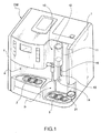
Figure 1 is a perspective view of an apparatus according to the invention, incorporated in an espresso coffee-making machine in which a rotary stirring device of the apparatus is shown in the raised, rest position; -
Figure 2 is a view similar to that ofFigure 1 and shows the rotary stirring device in the lowered, working position for the preparation of a hot beverage; -
Figure 3 is a view similar to the preceding drawings and shows the rotary stirring device in the lowered position, partially immersed in a cleaning container for the cleaning of its rotary stirring element; -
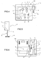
Figure 4 is a schematic view of an apparatus according to the invention, incorporated in a coffee-making machine, a hot steam source of which it shares; -
Figure 5 is a schematic view of a rotary stirring device in which the hot steam can be supplied into a vessel or container through the rotatable stirring shaft; and -
Figure 6 is a schematic front view of a variant in which the apparatus according to the invention shares the steam source of a coffee-making machine in which it is incorporated, the source including a conventional steam-dispensing nozzle or lance. - An apparatus according to the invention for the preparation of hot beverages will now be described in detail with reference to an embodiment in which the apparatus is incorporated as an accessory in a conventional espresso coffee-making machine.
- The apparatus according to the invention may, however, also be constructed in a "stand-alone" version, that is, as an independent apparatus.
- An espresso coffee-making machine of known type is generally indicated CM in
Figures 1 to 4 . The machine comprises asupport housing 1 in the front portion of which two working areas, indicated A and B respectively, are defined. - The working area A is intended for the preparation of espresso coffee which is poured into one or more small cups or the like (not shown), that are positioned on a
support surface 2 beforehand. - The working area B is intended for the preparation of hot beverages, in particular milk-based beverages, by means of an apparatus according to the invention. A beverage of this type is prepared in particular in a vessel R (
Figure 2 ) such as, for example, a glass which is placed on asupport surface 3 of the working area B. - The apparatus according to the present invention comprises a hot steam source. In the embodiment shown by way of example in
Figures 1 to 4 , the steam source is that with which the coffee-making machine CM is typically provided; in the embodiment shown schematically inFigure 4 , the steam source comprises awater reservoir 4 from which apump 5 draws a flow of water which it sends to a heat exchanger 6, for example, of the so-called instantaneous type, which is provided with a heating resistor 7. In the heat exchanger 6, the flow of water is converted into a flow of hot steam which is sent towards arotary stirring device 10, for example, through aflexible duct 8. - Steam sources of other types may however be used to send a flow of hot steam into the vessel R that is arranged in the working area B.
- In the embodiment shown, the
stirring device 10 is mounted in the front portion of thesupport housing 1 of the coffee-making machine CM. - With reference to
Figure 1 , in the embodiment illustrated, thestirring device 10 comprises ahousing 11 which houses an electric motor 12 (shown in broken outline inFigure 1 ) suitable for rotating arotatable shaft 13 which carries, at its lower end, a stirringrotor 14 of known type. - The
shaft 13 and the associatedrotor 14 extend below thehousing 11. - The
rotary stirring device 10 is movable relative to thesupport housing 1 of the machine CM between a raised, rest position shown inFigure 1 , in which it allows a vessel R to be positioned in the working area B for the preparation of a beverage, and a lowered, working position shown inFigure 2 , in which theshaft 13 and the associatedstirring rotor 14 extend in the working area in the vessel R positioned therein. - For this purpose, the stirring
device 10 may advantageously be mounted so as to be slidable along avertical guide 15 provided in thesupport housing 1 of the coffee-making machine CM. - The arrangement may be such that the stirring
device 10 is movable between its rest position and its working position by means of an electrically-operated drive device, for example, including anelectric motor 16 and atransmission 17 of the rack-and-pinion type (seeFigure 4 ). The stirringdevice 10 may, however, also simply be movable manually along theguide 15 between the two above-mentioned positions and may be held in the working position and in the rest position by means of suitable known retaining devices. - In the embodiment shown in
Figures 1 to 5 , therotatable shaft 13 of thestirring device 10 has a longitudinal internal conduit which is shown in broken outline and indicated 16 inFigure 5 . This conduit is in communication, at the top, with a substantiallytransverse duct 17 provided in thehousing 11 and communicating with the steam source 4-7 by means of the flexible duct 8 (Figure 4 ). - In this embodiment, the
rotary stirring device 10 acts, at the same time, as a device for heating the milk or the like which is poured into the vessel R and is intended to be emulsified and "whipped", for example, for the preparation of a cappuccino. - As shown schematically in
Figure 4 , an electronic control unit ECU may be provided for coordinating the operation of the steam source (by means of theelectric pump 5 and the resistor 7 of the exchanger 6) with the movement of the stirring device 10 (controlled by means of theelectric motor 16 and the associated transmission 17), as well as with the - rotation of the
shaft 13 and of the associated stirring rotor 14 (controlled by the electric motor 12), in dependence on commands imparted by the user, for example, by means of a control keypad. - The electronic unit ECU is arranged, in particular, to bring about the movement of the stirring
device 10 between its rest position and its working position and the activation of the steam source 4-7 and of thestirring device 10 whilst theshaft 13 and the associatedrotor 14 extend in the vessel R which is arranged in the working area B for the preparation of a hot beverage. - Upon completion of the preparation of a hot beverage, the stirring
device 10 is returned to the raised, rest position shown inFigure 1 . The vessel R can then be removed from the working area B. Further ingredients, such as espresso coffee and, optionally, chocolate powder may be added to the whipped hot milk in the vessel in order to prepare a cappuccino or the like. - The above-described apparatus may advantageously, but not necessarily, be equipped with accessories which will now be described, to permit cleaning and sterilization of the
rotatable shaft 13 and of the associatedstirring rotor 14 which are inevitably soiled after the preparation of the hot beverage. - In the embodiment shown, the apparatus comprises a substantially beaker-shaped or cup-shaped cleaning container, indicated C in
Figures 1 to 3 and6 (seeFigure 3 in particular). - In the embodiment shown, the cleaning container C is carried by the end of an
arcuate support arm 21 which can be moved horizontally relative to thesupport housing 1 of the machine CM through anopening 22 in the housing (Figure 3 ). - The
support arm 21 and the associated cleaning container C are movable, in particular, between a rest position shown inFigures 1 ,2 and6 in which they extend outside the working area B, and a position of use, shown inFigure 3 , in which they extend in the working area B with the cleaning container C beneath the stirring device andhot steam dispenser 10. - The
support arm 21 and the associated cleaning container C can be moved between their rest positions and their positions of use manually or in a motorized manner, for example, by means of anelectric motor 18 and an associatedtransmission 19 which are shown schematically inFigure 4 and, advantageously, are controlled by the same control unit ECU which was described above. - By means of a command imparted, for example, by means of a suitable push-button, the user can activate a quick cleaning cycle of the stirring device and steam source, which takes place substantially in the manner that will now be described.
- The cleaning cycle is started whilst the
rotary stirring device 10 and the cleaning container C are in their respective rest positions (Figure 1 ). - As a result of the starting of the cleaning cycle, the
support arm 21 and the cleaning container C are moved from the rest position to the position of use and thestirring device 10 is then moved down to the lowered position so that itsshaft 13 and the associatedstirring rotor 14 extend in the cleaning container C, as shown inFigure 3 . In this condition, the hot steam source 4-7 and theelectric motor 12 of the stirringdevice 11 are activated. A flow of hot steam thus passes through thelongitudinal conduit 16 inside theshaft 13 and then emerges from the lower end thereof, inside the cleaning container C, and thus collides with the stirringrotor 14 as well as the outer surface of theshaft 13. The combined effect of the action of the flow of steam at high temperature and of the speed of rotation imparted to theshaft 13 and to therotor 14 brings about detachment of the residues of milk etc. which are present inside and outside theshaft 13 and therotor 14. The high temperature of the steam also has the effect of sterilizing theshaft 13 and the associatedrotor 14 which are cleaned automatically in a few seconds. - Owing to the centrifugal force, the steam (and the residues of milk etc. transported thereby) is thrust onto the internal surface of the cleaning container C and cools thereon, condensing into drops which can advantageously be discharged through one or more drain holes provided in the cleaning container C, such as the hole indicated 23 in
Figure 3 . - Upon completion of the cleaning cycle, which may typically last for about ten seconds, both the unit formed by the
shaft 13 and by therotor 14, and the cleaning container C, are completely clean and sterilized. - These elements may advantageously be made of materials having anti-stick properties to prevent adhesion and thus facilitate the detachment of the residues. Upon completion of the cleaning cycle, the stirring
device 10 is returned to the raised, rest position and thesupport arm 21 with the associated cleaning container C is returned to the rest position. - In the above-described embodiments, the hot steam is supplied for the preparation of a beverage, as well as for any subsequent cleaning cycle, through an
axial conduit 16 provided in thesame shaft 13 which carries thestirring rotor 14. -
Figure 6 shows a variant in which the machine CM comprises, in known manner, a hot-steam dispensing nozzle or lance, indicated 30, which is located so as to be able to supply a flow of hot steam into the vessel R for the preparation of a beverage and into the cleaning container C when it is arranged in the working area B. - For this variant, the methods of operation for the preparation of a beverage and for an optional cleaning cycle are also very similar to those that are implemented in the embodiment described above.
- Naturally, the principle of the invention remaining the same, the forms of embodiment and details of construction may be varied widely with respect to those described and illustrated purely by way of non-limiting example, without thereby departing from the scope of the invention as defined in the appended claims.
Claims (8)
- An apparatus for the preparation of hot beverages, in particular milk-based beverages, such as cappuccino, hot chocolate and the like, comprising:a structure (1) wherein there is defined a working area (B) in which a vessel (R) can be positioned for the preparation of a beverage;a rotary stirring device (10) comprising a rotatable shaft (13) which carries a stirring rotor (14); the stirring device (10) being movable relative to the structure (1) between a raised, rest position and a lowered, working position, in which the shaft (13) and the associated rotor (14) extends above the working area (B) and in the working area (B) inside a vessel or container (R; C) positioned therein, respectively; andcontrol means (ECU) arranged for causing:- the movement of the stirring device (10) between its rest position and its working position;- the activation of the stirring device (10) whilst the shaft (13) and the rotor (14) of the latter extend in a vessel (R) arranged in the working area (B) for the preparation of a beverage; and- the lowering of the stirring device (10) from its rest position for cleaning the shaft (13) and the rotor (14);the apparatus being characterized by comprisinga hot steam source (4-7, 16; 30) arranged for supplying a flow of steam into a vessel or container (R; C) positioned in the working area (B),the apparatus also comprisinga substantially beaker-shaped cleaning container (C) which is movable relative to the structure (1) between a rest position and a position of use in which the cleaning container (C) extends outside and inside the working area (B), respectively; in the position of use, the cleaning container (C) being able to receive the shaft (13) and the rotor (14) of the stirring device (10) that has been lowered from its rest position, anddrive means (18, 19) suitable for causing the movement of the cleaning container (C);said control means (ECU) being arranged to activate said hot steam source (4-7) and to rotate the stirring device (10) whilst the shaft (13) and the rotor (14) of the latter extend in the cleaning container (C) in the working area (B).
- An apparatus according to claim 1, wherein the cleaning container (C) has a drain or discharge opening (23) in its lower portion.
- An apparatus according to claim 1 or 2, wherein the cleaning container (C) is movable horizontally between its rest and use positions.
- An apparatus according to any one of the preceding claims, wherein the structure (1) is the structure of a coffee-making machine (CM) with which the apparatus is associated and which is provided with a steam source (4-7) that is shared with the apparatus.
- An apparatus according to any one of the preceding claims, wherein the rotatable shaft (13) of the stirring device (10) is provided with a longitudinal conduit (16) which is connected or connectible to the steam source (4-7) and which opens into the working area (B) when the stirring device (10) is in the lowered position.
- An apparatus according to claim 4, wherein the machine (CM) has a dispensing nozzle or lance (30) which can be connected to the steam source (4-7) and can supply a flow of steam into a vessel or container (R; C) arranged in the working area (B).
- An apparatus according to any one of the preceding claims, comprising further drive means (16, 17) suitable for causing the movement of the stirring device (10).
- An apparatus according to any one of the preceding claims, wherein the stirring device (10) comprises an electric motor (12) for rotating the shaft (13) and the associated rotor (14).
Applications Claiming Priority (2)
| Application Number | Priority Date | Filing Date | Title |
|---|---|---|---|
| ITTO2010A000731A IT1402173B1 (en) | 2010-09-02 | 2010-09-02 | APPARATUS FOR THE PREPARATION OF A HOT DRINK, IN PARTICULAR A MILK BASED DRINK |
| PCT/IB2011/053836 WO2012029047A1 (en) | 2010-09-02 | 2011-09-01 | Apparatus for the preparation of a hot beverage, in particular a milk-based beverage |
Publications (2)
| Publication Number | Publication Date |
|---|---|
| EP2611342A1 EP2611342A1 (en) | 2013-07-10 |
| EP2611342B1 true EP2611342B1 (en) | 2016-11-16 |
Family
ID=43739129
Family Applications (1)
| Application Number | Title | Priority Date | Filing Date |
|---|---|---|---|
| EP11776021.5A Active EP2611342B1 (en) | 2010-09-02 | 2011-09-01 | Apparatus for the preparation of a hot beverage, in particular a milk-based beverage |
Country Status (5)
| Country | Link |
|---|---|
| US (1) | US9003957B2 (en) |
| EP (1) | EP2611342B1 (en) |
| AU (1) | AU2011297684B2 (en) |
| IT (1) | IT1402173B1 (en) |
| WO (1) | WO2012029047A1 (en) |
Families Citing this family (17)
| Publication number | Priority date | Publication date | Assignee | Title |
|---|---|---|---|---|
| FR2960405B1 (en) * | 2010-05-25 | 2013-01-18 | Cie Mediterraneenne Des Cafes | PRESSURE VARIATION INFUSION DEVICE |
| DE102012217007B4 (en) * | 2012-09-21 | 2019-10-24 | BSH Hausgeräte GmbH | Coffee machine with additional element |
| US9609978B2 (en) * | 2012-12-04 | 2017-04-04 | Koninklijke Philips N.V. | Jug for the preparation of beverages and beverage producing system |
| CH707837A1 (en) * | 2013-03-26 | 2014-09-30 | Schaerer Ag | Vending Machine and method for operating such a vending machine. |
| DE102014215689A1 (en) * | 2014-08-07 | 2016-02-11 | Franke Kaffeemaschinen Ag | Supply unit for supplying a liquid food to a beverage dispenser and method for cleaning at least one feed unit for supplying a liquid food to a beverage dispenser |
| ITUA20162284A1 (en) * | 2016-04-04 | 2017-10-04 | Iacobucci Hf Aerospace S P A | Cappuccino |
| FR3056896B1 (en) * | 2016-09-30 | 2018-10-26 | Seb S.A. | DEVICE FOR PREPARING BEVERAGES WITH A MOBILE VAPOR NOZZLE |
| CN107440520B (en) * | 2017-08-31 | 2019-06-28 | 温州职业技术学院 | The Switch of working position device of fully-automatic intelligent milk maker |
| CN108185820B (en) * | 2018-02-11 | 2020-08-18 | 杭州黑石机器人有限公司 | Automatic milk tea machine |
| FR3081674B1 (en) * | 2018-05-31 | 2020-05-15 | Seb S.A. | BEVERAGE PREPARATION MACHINE HAVING A ROTATING AGITATOR AND A COFFEE NOZZLE |
| FR3083070B1 (en) | 2018-06-28 | 2020-06-12 | Seb S.A. | ROTARY SHAKING DEVICE OF A BEVERAGE PREPARATION MACHINE HAVING A COUPLING SLEEVE |
| DE102018214563A1 (en) * | 2018-08-28 | 2020-03-05 | BSH Hausgeräte GmbH | Method for operating a vending machine |
| CN109381018B (en) * | 2018-11-09 | 2022-02-08 | 深圳市西啡科技有限公司 | Breakfast machine |
| IT201900012312A1 (en) * | 2019-07-18 | 2021-01-18 | De Longhi Appliances Srl | MILK FRUIT |
| US20220257046A1 (en) * | 2019-07-18 | 2022-08-18 | De' Longhi Appliances S.R.L. | Milk frother |
| JP7380247B2 (en) * | 2020-01-23 | 2023-11-15 | 富士電機株式会社 | beverage dispensing equipment |
| US11812892B1 (en) | 2022-04-25 | 2023-11-14 | Sharkninja Operating Llc | Fluid texturing device |
Family Cites Families (8)
| Publication number | Priority date | Publication date | Assignee | Title |
|---|---|---|---|---|
| JP2002367023A (en) * | 2001-06-08 | 2002-12-20 | Sanden Corp | Cup-type beverage vending machine |
| DE20300851U1 (en) * | 2003-01-21 | 2004-05-27 | Wik Far East Ltd. | Device for foaming a beverage and coffee machine with such a device |
| PT1746920E (en) * | 2004-05-18 | 2010-05-28 | Nestec Sa | Device for foaming milk, comprising external suction equipment |
| DE102004024721A1 (en) * | 2004-05-19 | 2005-12-15 | Melitta Haushaltsprodukte Gmbh & Co Kommanditgesellschaft | Device for foaming a liquid |
| FR2929091B1 (en) * | 2008-03-26 | 2010-04-02 | Seb Sa | MACHINE FOR PREPARING BEVERAGES COMPRISING AN INTEGRATED CONTAINER FOR CLEANING A STEAM NOZZLE |
| ITTO20080311A1 (en) | 2008-04-22 | 2009-10-23 | Lavazza Luigi Spa | MACHINE FOR THE PREPARATION OF DRINKS |
| DE102008021778A1 (en) * | 2008-04-30 | 2009-11-05 | Eugster/Frismag Ag | Process for the preparation and administration of milk froth or a beverage, device for carrying out the process, espresso machine with such a device and preparation vessel for use in such a device or espresso machine |
| DE102010007143B4 (en) * | 2010-02-05 | 2013-08-22 | Eugster/Frismag Ag | Coffee machine with a foaming device and means for cleaning the foaming device and a milk suction line and method for rinsing the milk suction line |
-
2010
- 2010-09-02 IT ITTO2010A000731A patent/IT1402173B1/en active
-
2011
- 2011-09-01 AU AU2011297684A patent/AU2011297684B2/en active Active
- 2011-09-01 EP EP11776021.5A patent/EP2611342B1/en active Active
- 2011-09-01 WO PCT/IB2011/053836 patent/WO2012029047A1/en not_active Ceased
- 2011-09-01 US US13/820,378 patent/US9003957B2/en active Active
Also Published As
| Publication number | Publication date |
|---|---|
| US20130152798A1 (en) | 2013-06-20 |
| ITTO20100731A1 (en) | 2012-03-03 |
| WO2012029047A1 (en) | 2012-03-08 |
| AU2011297684B2 (en) | 2015-02-05 |
| AU2011297684A1 (en) | 2013-03-21 |
| EP2611342A1 (en) | 2013-07-10 |
| IT1402173B1 (en) | 2013-08-28 |
| US9003957B2 (en) | 2015-04-14 |
Similar Documents
| Publication | Publication Date | Title |
|---|---|---|
| EP2611342B1 (en) | Apparatus for the preparation of a hot beverage, in particular a milk-based beverage | |
| RU2549060C2 (en) | Beverage dispensing device with safe cleaning unit | |
| CN106714631B (en) | Beverage preparation machine with flexible drop stop | |
| EP2531085B2 (en) | Beverage dispenser with hygienic cleaning cycle | |
| US9402502B2 (en) | Hot-beverage-making apparatus, in particular for milk beverages such as cappuccino, chocolate and the like | |
| EP2198762A1 (en) | Device for the preparation of hot beverages, in particular milk-based beverages such as cappuccino, chocolate and similar | |
| EP3223668A1 (en) | Liquid dispensing machine with compact drop stop | |
| RU2557492C2 (en) | Device for supply of hot water or water steam with storage position | |
| JP2013526358A5 (en) | ||
| GB2504493A (en) | Milk frother with magnetic drive | |
| CN210121077U (en) | Beverage preparation machine | |
| CN115721164A (en) | Method for preparing a very hot beverage in a container by a beverage dispensing machine |
Legal Events
| Date | Code | Title | Description |
|---|---|---|---|
| PUAI | Public reference made under article 153(3) epc to a published international application that has entered the european phase |
Free format text: ORIGINAL CODE: 0009012 |
|
| 17P | Request for examination filed |
Effective date: 20130319 |
|
| AK | Designated contracting states |
Kind code of ref document: A1 Designated state(s): AL AT BE BG CH CY CZ DE DK EE ES FI FR GB GR HR HU IE IS IT LI LT LU LV MC MK MT NL NO PL PT RO RS SE SI SK SM TR |
|
| DAX | Request for extension of the european patent (deleted) | ||
| 17Q | First examination report despatched |
Effective date: 20140410 |
|
| GRAP | Despatch of communication of intention to grant a patent |
Free format text: ORIGINAL CODE: EPIDOSNIGR1 |
|
| INTG | Intention to grant announced |
Effective date: 20160608 |
|
| GRAS | Grant fee paid |
Free format text: ORIGINAL CODE: EPIDOSNIGR3 |
|
| GRAA | (expected) grant |
Free format text: ORIGINAL CODE: 0009210 |
|
| AK | Designated contracting states |
Kind code of ref document: B1 Designated state(s): AL AT BE BG CH CY CZ DE DK EE ES FI FR GB GR HR HU IE IS IT LI LT LU LV MC MK MT NL NO PL PT RO RS SE SI SK SM TR |
|
| REG | Reference to a national code |
Ref country code: GB Ref legal event code: FG4D |
|
| REG | Reference to a national code |
Ref country code: CH Ref legal event code: EP |
|
| REG | Reference to a national code |
Ref country code: IE Ref legal event code: FG4D |
|
| REG | Reference to a national code |
Ref country code: AT Ref legal event code: REF Ref document number: 845058 Country of ref document: AT Kind code of ref document: T Effective date: 20161215 |
|
| REG | Reference to a national code |
Ref country code: DE Ref legal event code: R096 Ref document number: 602011032515 Country of ref document: DE |
|
| PG25 | Lapsed in a contracting state [announced via postgrant information from national office to epo] |
Ref country code: LV Free format text: LAPSE BECAUSE OF FAILURE TO SUBMIT A TRANSLATION OF THE DESCRIPTION OR TO PAY THE FEE WITHIN THE PRESCRIBED TIME-LIMIT Effective date: 20161116 |
|
| REG | Reference to a national code |
Ref country code: NL Ref legal event code: MP Effective date: 20161116 |
|
| REG | Reference to a national code |
Ref country code: LT Ref legal event code: MG4D |
|
| REG | Reference to a national code |
Ref country code: AT Ref legal event code: MK05 Ref document number: 845058 Country of ref document: AT Kind code of ref document: T Effective date: 20161116 |
|
| PG25 | Lapsed in a contracting state [announced via postgrant information from national office to epo] |
Ref country code: LT Free format text: LAPSE BECAUSE OF FAILURE TO SUBMIT A TRANSLATION OF THE DESCRIPTION OR TO PAY THE FEE WITHIN THE PRESCRIBED TIME-LIMIT Effective date: 20161116 Ref country code: NO Free format text: LAPSE BECAUSE OF FAILURE TO SUBMIT A TRANSLATION OF THE DESCRIPTION OR TO PAY THE FEE WITHIN THE PRESCRIBED TIME-LIMIT Effective date: 20170216 Ref country code: SE Free format text: LAPSE BECAUSE OF FAILURE TO SUBMIT A TRANSLATION OF THE DESCRIPTION OR TO PAY THE FEE WITHIN THE PRESCRIBED TIME-LIMIT Effective date: 20161116 Ref country code: NL Free format text: LAPSE BECAUSE OF FAILURE TO SUBMIT A TRANSLATION OF THE DESCRIPTION OR TO PAY THE FEE WITHIN THE PRESCRIBED TIME-LIMIT Effective date: 20161116 Ref country code: GR Free format text: LAPSE BECAUSE OF FAILURE TO SUBMIT A TRANSLATION OF THE DESCRIPTION OR TO PAY THE FEE WITHIN THE PRESCRIBED TIME-LIMIT Effective date: 20170217 |
|
| PG25 | Lapsed in a contracting state [announced via postgrant information from national office to epo] |
Ref country code: AT Free format text: LAPSE BECAUSE OF FAILURE TO SUBMIT A TRANSLATION OF THE DESCRIPTION OR TO PAY THE FEE WITHIN THE PRESCRIBED TIME-LIMIT Effective date: 20161116 Ref country code: PT Free format text: LAPSE BECAUSE OF FAILURE TO SUBMIT A TRANSLATION OF THE DESCRIPTION OR TO PAY THE FEE WITHIN THE PRESCRIBED TIME-LIMIT Effective date: 20170316 Ref country code: PL Free format text: LAPSE BECAUSE OF FAILURE TO SUBMIT A TRANSLATION OF THE DESCRIPTION OR TO PAY THE FEE WITHIN THE PRESCRIBED TIME-LIMIT Effective date: 20161116 Ref country code: FI Free format text: LAPSE BECAUSE OF FAILURE TO SUBMIT A TRANSLATION OF THE DESCRIPTION OR TO PAY THE FEE WITHIN THE PRESCRIBED TIME-LIMIT Effective date: 20161116 Ref country code: ES Free format text: LAPSE BECAUSE OF FAILURE TO SUBMIT A TRANSLATION OF THE DESCRIPTION OR TO PAY THE FEE WITHIN THE PRESCRIBED TIME-LIMIT Effective date: 20161116 Ref country code: HR Free format text: LAPSE BECAUSE OF FAILURE TO SUBMIT A TRANSLATION OF THE DESCRIPTION OR TO PAY THE FEE WITHIN THE PRESCRIBED TIME-LIMIT Effective date: 20161116 Ref country code: RS Free format text: LAPSE BECAUSE OF FAILURE TO SUBMIT A TRANSLATION OF THE DESCRIPTION OR TO PAY THE FEE WITHIN THE PRESCRIBED TIME-LIMIT Effective date: 20161116 |
|
| PG25 | Lapsed in a contracting state [announced via postgrant information from national office to epo] |
Ref country code: RO Free format text: LAPSE BECAUSE OF FAILURE TO SUBMIT A TRANSLATION OF THE DESCRIPTION OR TO PAY THE FEE WITHIN THE PRESCRIBED TIME-LIMIT Effective date: 20161116 Ref country code: DK Free format text: LAPSE BECAUSE OF FAILURE TO SUBMIT A TRANSLATION OF THE DESCRIPTION OR TO PAY THE FEE WITHIN THE PRESCRIBED TIME-LIMIT Effective date: 20161116 Ref country code: EE Free format text: LAPSE BECAUSE OF FAILURE TO SUBMIT A TRANSLATION OF THE DESCRIPTION OR TO PAY THE FEE WITHIN THE PRESCRIBED TIME-LIMIT Effective date: 20161116 Ref country code: SK Free format text: LAPSE BECAUSE OF FAILURE TO SUBMIT A TRANSLATION OF THE DESCRIPTION OR TO PAY THE FEE WITHIN THE PRESCRIBED TIME-LIMIT Effective date: 20161116 Ref country code: CZ Free format text: LAPSE BECAUSE OF FAILURE TO SUBMIT A TRANSLATION OF THE DESCRIPTION OR TO PAY THE FEE WITHIN THE PRESCRIBED TIME-LIMIT Effective date: 20161116 |
|
| REG | Reference to a national code |
Ref country code: DE Ref legal event code: R097 Ref document number: 602011032515 Country of ref document: DE |
|
| PG25 | Lapsed in a contracting state [announced via postgrant information from national office to epo] |
Ref country code: BG Free format text: LAPSE BECAUSE OF FAILURE TO SUBMIT A TRANSLATION OF THE DESCRIPTION OR TO PAY THE FEE WITHIN THE PRESCRIBED TIME-LIMIT Effective date: 20170216 Ref country code: SM Free format text: LAPSE BECAUSE OF FAILURE TO SUBMIT A TRANSLATION OF THE DESCRIPTION OR TO PAY THE FEE WITHIN THE PRESCRIBED TIME-LIMIT Effective date: 20161116 Ref country code: BE Free format text: LAPSE BECAUSE OF FAILURE TO SUBMIT A TRANSLATION OF THE DESCRIPTION OR TO PAY THE FEE WITHIN THE PRESCRIBED TIME-LIMIT Effective date: 20161116 |
|
| PLBE | No opposition filed within time limit |
Free format text: ORIGINAL CODE: 0009261 |
|
| STAA | Information on the status of an ep patent application or granted ep patent |
Free format text: STATUS: NO OPPOSITION FILED WITHIN TIME LIMIT |
|
| REG | Reference to a national code |
Ref country code: FR Ref legal event code: PLFP Year of fee payment: 7 |
|
| 26N | No opposition filed |
Effective date: 20170817 |
|
| PG25 | Lapsed in a contracting state [announced via postgrant information from national office to epo] |
Ref country code: SI Free format text: LAPSE BECAUSE OF FAILURE TO SUBMIT A TRANSLATION OF THE DESCRIPTION OR TO PAY THE FEE WITHIN THE PRESCRIBED TIME-LIMIT Effective date: 20161116 |
|
| REG | Reference to a national code |
Ref country code: CH Ref legal event code: PL |
|
| PG25 | Lapsed in a contracting state [announced via postgrant information from national office to epo] |
Ref country code: MC Free format text: LAPSE BECAUSE OF FAILURE TO SUBMIT A TRANSLATION OF THE DESCRIPTION OR TO PAY THE FEE WITHIN THE PRESCRIBED TIME-LIMIT Effective date: 20161116 |
|
| REG | Reference to a national code |
Ref country code: IE Ref legal event code: MM4A |
|
| PG25 | Lapsed in a contracting state [announced via postgrant information from national office to epo] |
Ref country code: LU Free format text: LAPSE BECAUSE OF NON-PAYMENT OF DUE FEES Effective date: 20170901 |
|
| PG25 | Lapsed in a contracting state [announced via postgrant information from national office to epo] |
Ref country code: IE Free format text: LAPSE BECAUSE OF NON-PAYMENT OF DUE FEES Effective date: 20170901 Ref country code: CH Free format text: LAPSE BECAUSE OF NON-PAYMENT OF DUE FEES Effective date: 20170930 Ref country code: LI Free format text: LAPSE BECAUSE OF NON-PAYMENT OF DUE FEES Effective date: 20170930 |
|
| PG25 | Lapsed in a contracting state [announced via postgrant information from national office to epo] |
Ref country code: MT Free format text: LAPSE BECAUSE OF NON-PAYMENT OF DUE FEES Effective date: 20170901 |
|
| REG | Reference to a national code |
Ref country code: FR Ref legal event code: PLFP Year of fee payment: 8 |
|
| PG25 | Lapsed in a contracting state [announced via postgrant information from national office to epo] |
Ref country code: HU Free format text: LAPSE BECAUSE OF FAILURE TO SUBMIT A TRANSLATION OF THE DESCRIPTION OR TO PAY THE FEE WITHIN THE PRESCRIBED TIME-LIMIT; INVALID AB INITIO Effective date: 20110901 |
|
| PG25 | Lapsed in a contracting state [announced via postgrant information from national office to epo] |
Ref country code: CY Free format text: LAPSE BECAUSE OF NON-PAYMENT OF DUE FEES Effective date: 20161116 |
|
| PG25 | Lapsed in a contracting state [announced via postgrant information from national office to epo] |
Ref country code: MK Free format text: LAPSE BECAUSE OF FAILURE TO SUBMIT A TRANSLATION OF THE DESCRIPTION OR TO PAY THE FEE WITHIN THE PRESCRIBED TIME-LIMIT Effective date: 20161116 |
|
| PG25 | Lapsed in a contracting state [announced via postgrant information from national office to epo] |
Ref country code: TR Free format text: LAPSE BECAUSE OF FAILURE TO SUBMIT A TRANSLATION OF THE DESCRIPTION OR TO PAY THE FEE WITHIN THE PRESCRIBED TIME-LIMIT Effective date: 20161116 |
|
| PG25 | Lapsed in a contracting state [announced via postgrant information from national office to epo] |
Ref country code: AL Free format text: LAPSE BECAUSE OF FAILURE TO SUBMIT A TRANSLATION OF THE DESCRIPTION OR TO PAY THE FEE WITHIN THE PRESCRIBED TIME-LIMIT Effective date: 20161116 Ref country code: IS Free format text: LAPSE BECAUSE OF FAILURE TO SUBMIT A TRANSLATION OF THE DESCRIPTION OR TO PAY THE FEE WITHIN THE PRESCRIBED TIME-LIMIT Effective date: 20170316 |
|
| P01 | Opt-out of the competence of the unified patent court (upc) registered |
Effective date: 20230601 |
|
| PGFP | Annual fee paid to national office [announced via postgrant information from national office to epo] |
Ref country code: DE Payment date: 20250919 Year of fee payment: 15 |
|
| PGFP | Annual fee paid to national office [announced via postgrant information from national office to epo] |
Ref country code: GB Payment date: 20250923 Year of fee payment: 15 |
|
| PGFP | Annual fee paid to national office [announced via postgrant information from national office to epo] |
Ref country code: FR Payment date: 20250924 Year of fee payment: 15 |
|
| PGFP | Annual fee paid to national office [announced via postgrant information from national office to epo] |
Ref country code: IT Payment date: 20250930 Year of fee payment: 15 |