EP2611315B1 - A filter mask having one or more malleable stiffening members - Google Patents
A filter mask having one or more malleable stiffening members Download PDFInfo
- Publication number
- EP2611315B1 EP2611315B1 EP11822474.0A EP11822474A EP2611315B1 EP 2611315 B1 EP2611315 B1 EP 2611315B1 EP 11822474 A EP11822474 A EP 11822474A EP 2611315 B1 EP2611315 B1 EP 2611315B1
- Authority
- EP
- European Patent Office
- Prior art keywords
- mask
- filter
- wearer
- stiffening member
- filter mask
- Prior art date
- Legal status (The legal status is an assumption and is not a legal conclusion. Google has not performed a legal analysis and makes no representation as to the accuracy of the status listed.)
- Active
Links
Images


Classifications
-
- A—HUMAN NECESSITIES
- A62—LIFE-SAVING; FIRE-FIGHTING
- A62B—DEVICES, APPARATUS OR METHODS FOR LIFE-SAVING
- A62B23/00—Filters for breathing-protection purposes
- A62B23/02—Filters for breathing-protection purposes for respirators
- A62B23/025—Filters for breathing-protection purposes for respirators the filter having substantially the shape of a mask
-
- A—HUMAN NECESSITIES
- A41—WEARING APPAREL
- A41D—OUTERWEAR; PROTECTIVE GARMENTS; ACCESSORIES
- A41D13/00—Professional, industrial or sporting protective garments, e.g. surgeons' gowns or garments protecting against blows or punches
- A41D13/05—Professional, industrial or sporting protective garments, e.g. surgeons' gowns or garments protecting against blows or punches protecting only a particular body part
- A41D13/11—Protective face masks, e.g. for surgical use, or for use in foul atmospheres
- A41D13/1107—Protective face masks, e.g. for surgical use, or for use in foul atmospheres characterised by their shape
- A41D13/1115—Protective face masks, e.g. for surgical use, or for use in foul atmospheres characterised by their shape with a horizontal pleated pocket
-
- A—HUMAN NECESSITIES
- A41—WEARING APPAREL
- A41D—OUTERWEAR; PROTECTIVE GARMENTS; ACCESSORIES
- A41D13/00—Professional, industrial or sporting protective garments, e.g. surgeons' gowns or garments protecting against blows or punches
- A41D13/05—Professional, industrial or sporting protective garments, e.g. surgeons' gowns or garments protecting against blows or punches protecting only a particular body part
- A41D13/11—Protective face masks, e.g. for surgical use, or for use in foul atmospheres
- A41D13/1161—Means for fastening to the user's head
-
- A—HUMAN NECESSITIES
- A62—LIFE-SAVING; FIRE-FIGHTING
- A62B—DEVICES, APPARATUS OR METHODS FOR LIFE-SAVING
- A62B18/00—Breathing masks or helmets, e.g. affording protection against chemical agents or for use at high altitudes or incorporating a pump or compressor for reducing the inhalation effort
- A62B18/02—Masks
- A62B18/025—Halfmasks
-
- A—HUMAN NECESSITIES
- A62—LIFE-SAVING; FIRE-FIGHTING
- A62B—DEVICES, APPARATUS OR METHODS FOR LIFE-SAVING
- A62B18/00—Breathing masks or helmets, e.g. affording protection against chemical agents or for use at high altitudes or incorporating a pump or compressor for reducing the inhalation effort
- A62B18/08—Component parts for gas-masks or gas-helmets, e.g. windows, straps, speech transmitters, signal-devices
-
- A—HUMAN NECESSITIES
- A41—WEARING APPAREL
- A41D—OUTERWEAR; PROTECTIVE GARMENTS; ACCESSORIES
- A41D2400/00—Functions or special features of garments
- A41D2400/42—Foldable
Definitions
- US 2009/0205666 discloses a face mask having mask material and ties or ear loops coupled to the mask material.
- the face mask is flat until worn.
- the mask material has an outside and an inside, which inside is designed to be against the wearer's face when the mask is worn.
- a deformable nose strip is provided near a top edge of the mask material The nose strip is preformed into a contour for fitting about the nose. The contour bows out from the inside to the outside.
- a wearer donning the mask intuitively knows to orient the contour to the wearer's nose, wherein the inside is automatically positioned against the wearer's face.
- a filter mask comprising: a filter material having an inner surface to be worn against a wearer's face, the filter material comprising at least one pleat for folding and unfolding the filter material such that when folded the filter material assumes a generally flat storage configuration having upper, lower and side edges and such that when unfolded the filter material forms a mask configured to cover the nose and mouth of the wearer, the at least one pleat disposed between at least the upper and lower edges and configured to fit over a chin of the wearer when unfolded; (i) an upper malleable stiffening member attached to or within the filter material proximate to the upper edge, the upper malleable stiffening member configured to conform the filter material to at least a nose portion and a cheek portion of the face of the wearer, the upper malleable stiffening member having a bend portion indicating at least the inner surface and the nose portion of the filter mask and a means for securing the filter material to the wearer's face comprising first and second ear loops
- the new filter masks provided allow a comfortable and better fit over a wider range of facial sizes and shapes.
- the filter masks are light weight and may be stored in a folded configuration.
- a bend portion e.g., crimp
- a malleable stiffening member e.g., metal strip
- a malleable stiffening member e.g., metal strip
- the user can pinch the malleable stiffening members to obtain a secure and comfortable fit to the mask and, therefore, have the mask custom fit to his/her face.
- a filter mask which provides a secure fit and reduces leakage of material around the top, bottom and edges of the masks.
- the filter mask provided exhibits a high bacterial filtration efficiency while it resists collapsing on the mouth of the wearer that may cause discomfort.
- a filter mask comprising: a filter material having an inner surface to be worn against a wearer's face, the filter material comprising at least one pleat for folding and unfolding the filter material such that when folded the filter material assumes a generally flat storage configuration having upper, lower and side edges and such that when unfolded the filter material forms a mask configured to cover the nose and mouth of the wearer, the at least one pleat disposed between at least the upper and lower edges and configured to fit over a chin of the wearer when unfolded; a malleable stiffening member attached to or within the filter material proximate to the upper edge, the malleable stiffening member configured to conform the filter material to at least a nose portion and a cheek portion of the face of the wearer, the malleable stiffening member having a bend portion indicating at least the inner surface and the nose portion of the filter mask; and a securing means for securing the filter material to the wearer's face.
- a filter mask comprising: a filter material having an inner surface to be worn against a wearer's face, and an outer surface, the filter material comprising at least one pleat for folding and unfolding the filter material such that when folded the filter material assumes a generally flat storage configuration having upper, lower and side edges and such that when unfolded the filter material forms a mask configured to cover the nose and mouth of the wearer, the at least one pleat disposed between the upper, lower and side edges and configured to fit over a chin of the wearer and to provide a breathing chamber when unfolded; a first malleable stiffening member attached to or within the filter material proximate to the upper edge, the first malleable stiffening member configured to conform the filter material to at least a nose portion and a cheek portion of the face of the wearer, the malleable stiffening member having a bend portion indicating at least the outer surface and the nose portion of the filter mask; a second malleable stiffening member attached to or within the filter material proxi
- a stack of filter masks comprising: a plurality of filter masks, each filter mask comprising a filter material having an inner surface to be worn against a wearer's face, and an outer surface, the filter material comprising at least one pleat for folding and unfolding the filter material such that when folded the filter material assumes a generally flat storage configuration having upper, lower and side edges and such that when unfolded the filter material forms a mask configured to cover the nose and mouth of the wearer, the at least one pleat disposed between the upper, and lower edges and configured to fit over a chin of the wearer when unfolded; a malleable stiffening member attached to or within the filter material proximate to the upper edge, the malleable stiffening member configured to conform the filter material to at least a nose portion and a cheek portion of the face of the wearer, the malleable stiffening member having a bend portion indicating at least the outer surface and the nose portion of the filter mask; a securing means for securing the filter
- a method of making a filter mask having a bend portion comprising providing a filter material having an inner surface to be worn against a wearer's face, the filter material comprising at least one pleat for folding and unfolding the filter material such that when folded the filter material assumes a generally flat storage configuration having upper, lower and side edges and such that when unfolded the filter material forms a mask configured to cover the nose and mouth of the wearer, the at least one pleat disposed between at least the upper and lower edges and configured to fit over a chin of the wearer when unfolded; inserting a malleable stiffening member or attaching it to at least the inner surface or outer surface and the nose portion of the filter mask to indicate at least the inner surface or outer surface and the nose portion of the filter mask; bending, folding, creasing, crimping, punching, etching, or angling the malleable stiffening member, and attaching a securing means to the filter material.
- a filter mask comprising a filter material having an inner surface to be worn against a wearer's face, the filter material comprising at least one pleat for folding and unfolding the filter material such that when folded the filter material assumes a generally flat storage configuration having upper, lower and side edges and such that when unfolded the filter material forms a mask configured to cover the nose and mouth of the wearer, the at least one pleat disposed between at least the upper and lower edges and configured to fit over a chin of the wearer when unfolded; a malleable stiffening member attached to or within the filter material proximate to the upper edge, the malleable stiffening member configured to conform the filter material to at least a nose portion and a cheek portion of the face of the wearer, a second malleable stiffening member attached to or within the filter material proximate to the lower edge, the second malleable stiffening member configured to conform the filter material to at least a chin portion and a jaw portion of the face of the wearer,
- a method of wearing a filter mask comprising: providing a filter mask to a wearer and conforming the malleable stiffening member to at least a nose portion and a cheek portion of the face of the wearer, the malleable stiffening member having a bend portion indicating at least the inner surface and the nose portion of the filter mask; and securing the filter mask to the wearer's face.
- a method of wearing a filter mask comprising: providing a filter mask to a wearer; conforming the first malleable stiffening member to at least a nose portion and a cheek portion of the face of the wearer, the malleable stiffening member having a bend portion, which is bent, creased, folded, or angled away from the inner surface that indicates at least the outer surface and the nose portion of the filter mask; conforming the second malleable stiffening member to at least a chin portion and a jaw portion of the face of the wearer, and securing the filter mask to the wearer's face.
- a malleable stiffening member includes one, two or more malleable stiffening members.
- Figure 1 illustrates an outside sectional view of the filter mask 10 in a folded configuration 11 prior to the filter mask being installed upon a wearer's face.
- this side of the filter mask 10 would face the outside environment and not touch the wearer's nose, cheeks, jaw and/or chin.
- the filter mask 10 may have application in medical, industrial, domestic, or other circumstances.
- the mask shown is an N95 respirator, which is a lightweight, nose-and-mouth respirator that provides protection for the wearer from microorganisms (e.g., bacteria, fungi, yeast, molds and viruses).
- the filter mask 10 is generally configured so as to provide a secure fit which reduces or prevents gaps and passage of material between the nostrils and mouth and the surrounding environment except through the filter material 13.
- the makeup of the filter material 13, and the pleating 20 used in connection with the filter mask 10 will be explained in detail shortly.
- the filter mask 10 has the particular advantage of allowing a secure fit to be created and to be maintained upon installation of the filter mask 10 on the face with the use of two ear loops 28 and 30.
- the filter mask 10 may be constructed of a wide variety of materials and is preferably disposable.
- the filter material 13 used to fabricate the filter mask 10 may vary according to the particular application of the filter mask 10. For example, when the filter mask 10 is to be used in a medical application, such as on members of a surgical team, it is common to use a three layer filter material. However, appropriate filter materials may be of a single or multiple layer design. Multi-layer material may be readily purchased in a precollated form, that is with the three layers already arranged, or the materials may be obtained separately and the filter material 13 formed in part of the process for forming the filter mask 10.
- a three or four layer filter medium might include an outer layer of a relatively porous paper-like material which provides durability and resistance against abrasion.
- the outer layer may also be generally stiffer than the other layers. By using a stiffer outer layer, the effectiveness of the various pleating arrangements is increased.
- the pleats 20 are disposed between the upper edge 12 and lower edge 25 and side edges 21 and 29 and may be incorporated in the body of the filter material 13 to hold the filter mask 10 in a cup-like shape when installed.
- the middle layer or layers of the filter material generally contain polyethylene or polypropylene, or other material, which exhibits the proper filtration characteristics. Glass fiber based materials may also have applications as the middle filtration layer.
- the innermost layer of the filter material to be worn next to or against the face generally comprises a soft material for providing a soft, non-irritating surface against which the facial skin will make contact.
- the filter material 13 In medical, dental and/or surgical applications, it is generally important that the filter material 13 also provide a high bacterial filtration efficiency (BFE).
- BFE bacterial filtration efficiency
- the BFE of a filter material is generally determined by the percentage of bacteria, such as Staphylococcus aureus or Bacillus stearothermophilus, that is able to migrate through the filter material under normal conditions. The fewer bacteria which are able to pass through the filter material 13, the higher the BFE.
- a BFE of 100% is desirable; however, efficiencies of as low as 25% are not uncommon among some types of prior art disposable filter masks. However, materials are available which provide BFE's of between 90 and 99%.
- a filter material having as high a BFE it is generally desirable to utilize a filter material having as high a BFE as possible so as to prevent release of nasopharyngeal organisms into the environment.
- the considerations that provide for a high BFE are the same considerations which provide that a filter material would be desirable in applications in industry and domestic use.
- a filter material which inhibits the migration of nearly all bacteria would generally also prevent inhalation of dust and dirt particles in industrial applications.
- those materials providing a high BFE are often also those materials which provide the least resistance to passage of gases through the filter material.
- the passage of gases through the filter material is important in maintaining the comfort of the wearer. It should be realized by one of ordinary skill in the art, however, that many applications might require greater or lesser standards of filtration than is commonly required in the medical environment. Therefore, while filter materials having an efficiency suitable for use with the present application available in the art, the best filter material is of little use if the air inhaled and exhaled by the wearer is allowed to escape the filter mask 10 without passing through the filter material 13. Indeed, the lack of a secure fit in the filter masks available in the prior art is important to the design and fabrication of filter masks.
- the present application provides a unique secure fit which reduces or prevents inhaled and exhaled air from leaking around the edges 12, 25, 21, and 29 of the filter mask 10, all while providing a superior fit on a wider range of facial sizes and shapes.
- the maintenance of such a secure fit greatly improves the overall efficiency of the filter mask 10.
- the structure of the filter mask 10 is generally prepared as a rectangular piece of flat filter material 13. However, it will be understood by those of ordinary skill in the art that other shapes of the filter mask can be made in order to cover additionally both the eyes, hair, and throat of the user. As such, the present application includes filter masks 10 that cover areas above and beyond simply the nose and mouth of the user.
- the filter mask may also incorporate any combination of known filter mask 10 features, such as visors or shields, sealing films, beard covers, etc.
- the filter mask 10 may be from about 5.5 inches to 7 inches across in length to cover the user's nose and mouth. In Figure 1 , the mask is shown as it would be packaged in its folded and flat configuration, where the outside surface is viewed.
- the filter mask 10 comprises a malleable stiffening member 14 attached to or imbedded in the filter material 13 at the masks upper edge 12.
- the malleable stiffening member 14 is configured to conform the filter material 13 to at least a nose portion and a cheek portion of the face of the wearer.
- a second malleable stiffening member 24 is attached to or within lower edge 25 of the filter material 13, as illustrated in Figure 1 .
- the second malleable stiffening member is configured to conform the filter material to at least a chin portion and a jaw portion of the face of the wearer.
- the second malleable member does not include a bend portion.
- it can include a bend portion that is different from the bend portion 15 in the nose and cheek portion of the mask provided that they can be distinguished (e.g., the bend portion 15 at the nose section can be creased at a larger angle than the optional bend portion in the chin piece).
- malleable stiffener or “malleable stiffening member” herein is meant to include the use of both malleable and flexible stiffeners. It is preferred that the malleable stiffeners 14, and 24 be placed adjacent to the upper 12 and lower edges 25 of the filter material 13, respectively. Alternatively, the malleable stiffeners 14, and 24 may be placed somewhere along the upper 12 and lower edges 25 of the filter material 13. The important property of the malleable stiffeners 14 and 24 is that the material be pliant enough to be bent to a shape that conforms to the face of the wearer, and then retain that shape.
- the filter mask 10 also has ear loop 30 attached to edges of the mask at attachment points 16 and 22 and ear loop 28 to edges of the mask at attachment points 18 and 26 used in donning the mask.
- the ear loops are attached to the outside surface of the mask.
- the loops can be attached to the inside surface of the mask.
- the upper portion (33 in Figure 3 ) of the filter mask 10 will refer to that portion which contacts the nose and cheek areas of the wearer while the lower portion (40 in Figure 3 ) of the filter mask 10 will be that portion which is in proximity to the lower jaw and chin of the wearer.
- the malleable stiffeners 14 and 24 can comprise any pliant material, such as a malleable metal or alloy, plastic, or the like.
- the malleable stiffeners comprise aluminum or other binding material which exhibits stiffening characteristics.
- the malleable stiffeners 14 and 24 can be attached to or imbedded within the inside or outside surface of the filter material.
- the malleable stiffening members can be attached to the filter mask and then covered with the same or different material used to make the mask.
- the malleable stiffening members can be attached to the mask by covering it with spunbonded polypropylene and ultrasonically sealing it to the outer surface of the mask.
- the malleable stiffening members can be attached to the mask by adhesive or other means for holding the malleable stiffening members to the mask.
- the first malleable stiffener 14 used for the nose portion of the mask may be from about 3 to 6 inches in length and from about 0.025 or 0.125 or 0.25 or 0.5 inches in height and from about 0.01 or 0.02 or 0.05 or 0.125 or 0.25 inches thick.
- the second malleable stiffener 24 used for the chin portion of the mask may be from about 1.5 to 5 inches in length and from about 0.025 or 0.125 or 0.25 or 0.5 inches in height and from about 0.01 or 0.02 or 0.05 or 0.125 or 0.25 inches thick.
- the first malleable stiffener 14 used in the nose portion can have a length that is larger or the same size as the length of second malleable stiffener 24 that is used in the chin portion of the filter mask.
- the second malleable stiffener 24 can be smaller than the first malleable stiffener 14.
- a method of wearing a filter mask comprising: providing a filter mask to a wearer and conforming the malleable stiffening member to at least a nose portion and/or a cheek portion of the face of the wearer, the malleable stiffening member having a bend portion indicating at least the inner surface and the nose portion of the filter mask; and securing the filter mask to the wearer's face.
- the user takes his/her fingertips and applies suitable pressure and bends the malleable stiffening member to conform it to the nose portion and/or cheek portion of the wearer.
- the malleable stiffening member is sized, has a length and thickness that allows it to be bent and conform to the nose portion and/or cheek portion of the wearer and a corresponding portion of the mask conforms to the nose portion and/or cheek portion of the wearer as well.
- a method of wearing a filter mask comprising: providing a filter mask to a wearer; conforming the first malleable stiffening member to at least a nose portion and/or a cheek portion of the face of the wearer, the malleable stiffening member having a bend portion, which is bent, creased, folded, or angled away from the inner surface that indicates at least the outer surface and the nose portion of the filter mask; conforming the second malleable stiffening member to at least a chin portion and/or a jaw portion of the face of the wearer, and securing the filter mask to the wearer's face.
- the user takes his/her fingertips and applies suitable pressure and bends the first malleable stiffening member to conform it to the nose portion and/or cheek portion of the wearer.
- the first malleable stiffening member is sized, has a length and thickness that allows it to be bent and conform to the nose portion and/or cheek portion of the wearer and a corresponding portion of the mask contacting the first malleable stiffening member conforms to the corresponding nose portion and/or cheek portion of the wearer as well.
- the second malleable stiffening member the user takes his/her fingertips and applies suitable pressure and bends the second malleable stiffening member to conform it to the chin portion and/or jaw portion of the wearer.
- the second malleable stiffening member is sized, has a length and thickness that allows it to be bent and conform to the chin portion and/or jaw portion of the wearer and a corresponding portion of the mask contacting the second malleable stiffening member conforms to the corresponding chin portion and/or jaw portion of the wearer as well.
- the malleable stiffening member 14 has a bend portion 15 indicating at least the inner surface, outer surface, center and/or the nose portion of the filter mask.
- the bend portion or crimp includes an angular or rounded shape made by pinching, folding, punching or bending the malleable stiffening member 14 to cause a cavity, indentation, recess, crease, or trough on the inside surface of the mask (not shown) and a projection, peak, protrusion, elevation or ridge on the outside surface of the mask (shown).
- the bend portion 15 includes making a ridge or fold by pinching the malleable stiffening member 14 by hand or machine.
- the bend portion 15 is shown generally in the center of the malleable stiffening member 14, it will be understood that the bend portion 15 can be disposed to the left, or right of center.
- the bend portion 15 or crimp may be located by the nose portion of the mask on the outer or inner surface and be angled or crimped in the direction away from the nose so that the user can bend it further for a custom fit around the nose and check area. In this way, the bend portion can be "pre-bent” or "pre-crimped” by the manufacturer.
- the bend portion will cause the inner surface of the mask that is to be placed against the user's nose to have a cavity, indentation, recess, crease, or trough on the inside surface of the mask and as the malleable stiffening member 14 is further pinched, bent or folded (as shown by the arrows in Figure 2A ), a cavity, indentation, recess, crease, or trough becomes larger to accommodate the nose.
- the user will have a visual indication of where the top of the mask is, where the nose section of the mask is and/or where the center of the mask is for those examples where the bend portion is disposed within the center or generally within the center of the malleable stiffening member 14.
- the bend portion 15 allows the user to identify the outside of the mask, the inside of the mask, top of the mask, and/or center of the mask. In some examples, the bend portion 15 is packaged (not shown) at least partially bent so that the cavity, indentation, recess, crease, or trough is visible on the interior of the mask.
- the bend portion 15 or crimp is typically formed from the same material as the malleable stiffening member. However, the same or different material may be used as long as the bend portion will cause a crease or fold in the filter material and allow the user to identify the top, center, inside and/or outside of the mask.
- the bend portion may be formed from any suitable material, such as an elastic material (e.g. a polymer), inelastic material, a nonwoven, knit, ribbon, cloth, wire, metal or the like.
- the bend portion may be bent before use by the manufacturer by about 1 to about 5 degrees, by about 1 to about 10 degrees, or by about 5 to about 20 degrees. In some examples, the bend portion may be bent before use by the manufacturer so that the bend portion projects out of the inner or outer surface of the mask by about 0.25 mm to about 0.5mm, or by about 1 mm to about 5 mm or by about 1 mm to about 10mm or by about 5 mm to about 20 mm, or by about 10 mm to about 30 mm or by about 35 mm to about 60 mm. In some examples, the bend portion is designed for easy bending around the ridge of the nose.
- the bend portion may be substantially deformable so that a wearer is able to bend, pinch or fold the bend portion and/or the malleable stiffening member between two or more fingers when gripping it as it is put around the ridge of the nose.
- a stack of filter masks comprising: a plurality of filter masks, each filter mask comprising a filter material having an inner surface to be worn against a wearer's face, and an outer surface, the filter material comprising at least one pleat for folding and unfolding the filter material such that when folded the filter material assumes a generally flat storage configuration having upper, lower and side edges and such that when unfolded the filter material forms a mask configured to cover the nose and mouth of the wearer, the at least one pleat disposed between the upper, and lower edges and configured to fit over a chin of the wearer when unfolded; a malleable stiffening member attached to or within the filter material proximate to the upper edge, the malleable stiffening member configured to conform the filter material to at least a nose portion and a cheek portion of the face of the wearer, the malleable
- Figure 2A illustrates a top side view of the malleable stiffening member 31 (e.g., metal strip) having a bend portion shown as a crimp or crease.
- the bend portion has a projection, peak, protrusion, elevation or ridge 32A that extends out and is visible on the outside surface of the mask (not shown).
- the bend portion has a cavity, indentation, recess, crease, or trough 32B on the inside of the mask that is visible on the inside surface of the mask.
- the stiffening member 31 would have this configuration when attached to the mask.
- the mask would be in a flat and/or folded configuration.
- the bend portion may be substantially deformable so that a wearer is able to bend or fold the bend portion and/or the malleable stiffening member in the direction of the arrows shown using two or more fingers when gripping it as it is put around the ridge of the nose.
- the wearer By employing a bend portion in the malleable stiffening member 31, which is placed in the center of the filter mask, the wearer will see a projection, peak, protrusion, elevation, or ridge or other marker visible on the outside surface of the mask, or a cavity, indentation, recess, crease, or trough or other marker visible on the inside surface of the mask and know where the top inside or outside, and/or center of the mask is and where the nose portion of the mask is to be placed on the face.
- the bend portion can be any shape (e.g., regular, irregular, symmetrical or asymmetrical shape).
- the bend portion causes a projection, peak, protrusion, elevation, or ridge or other marker on the top front, outside and/or center portion of the mask so that the wearer will know these portions of the mask and know the right side of the mask should be facing the outside environment and not the wearer's nose or face. In this way, the filter mask of the present application reduces the risk that the wearer will wear the mask incorrectly.
- Figure 2B illustrates a top view of the malleable stiffening member 31 having a bend portion shown as it would start to bend around the nose if the filter mask (not shown) was unfolded.
- the bend portion has a projection, peak, protrusion, elevation or ridge 32A that extends out and is visible on the outside surface of the mask (not shown).
- the projection increases as the malleable stiffening member 31 is further bent or pinched.
- the bend portion has a cavity, indentation, recess, crease, or trough 32B on the inside of the mask that is visible on the inside surface of the mask and gets bigger as the malleable stiffening member is further bent, pinched or folded.
- the stiffening member 31 would have this configuration when attached to or in the unfolded mask.
- the bend portion like the malleable stiffening member 31 may be substantially deformable so that a wearer is able to bend or fold the bend portion and/or the malleable stiffening member using two or more fingers when gripping it as it is put around the ridge of the nose.
- the bend is in a vertical direction relative to the one or more pleats.
- the bend portion 32 is crimped, bent, creased, folded, or angled toward the inner surface or outer surface of the filter mask by about 1 to 10 degrees or by 0.5 mm to about 50 mm.
- the crimp can be from 1 mm, 10 mm, 15 mm, 20 mm, 30 mm, 35 mm, 40 mm, 45 mm, 50 mm, 55 mm, 60 mm, or 65 mm.
- the filter mask may be attached to the user by a securing means that can attach the mask to the user.
- the securing means may be a pair of manual tie straps that are wrapped around the head of the user and are connected to one another, or the securing means may be ear loops (28 and 30 in Figure 1 ), elastic bands wrapped around the head of the user, a hook and loop type fastener arrangement (e.g. VELCRO® fasteners), or a connection directly attaching the face mask to a hair cap.
- the ear loops (28 and 30 in Figure 1 ) can be attached to the inner or outer surface of the mask at upper edges 16 and 18 and lower edges 22 and 26.
- the attachment points may be in from the edge by, for example, from about 1/8 th of an inch to 1 inch. The closer together the ear loops are, the tighter the fit and the mask will reduce gaps and leakage of inhaled and exhaled air.
- the loop is positioned so as to be balanced in the wearer's hand, thereby stabilizing the mask for donning.
- the loop may be formed from any suitable material, such as an elastic material (e.g. a polymer), inelastic material, a nonwoven, knit, ribbon, cloth, wire, and so forth.
- an elastic material e.g. a polymer
- inelastic material e.g. a nonwoven, knit, ribbon, cloth, wire, and so forth.
- the term “elastic” refers to the ability of a material to recover its size and shape after deformation.
- the term “inelastic” refers to the inability of a material to recover its size and shape after deformation.
- the loop is formed from the same material selected to form the outside surface of the mask.
- the loop may be bonded or otherwise affixed to the outside surface or inside surface of the mask. Examples of suitable techniques include adhesive bonding, thermal bonding, stitching, and so forth.
- the term “adhesive” refers to the property of any material that allows the material to bond together substrates by surface attachment.
- the loop is generally sized and positioned to facilitate gripping by a wearer, both prior to, during, and after donning.
- the loop 30 may be more or less than about 80 mm (0.08 m) in length as measured from the first end 16 to the second end 22 along the length of the loop. In other examples, the loop 30 may be less than about 60 mm (0.06 m) in length. In yet other embodiments, the loop 30 may be less than about 40 mm (0.04 m) in length. Where, in some embodiments, the loop is formed from an elastic material, the loop may have a fully extended length of 200 mm (0.200 m) or more. In some examples, the loop is from about 4 to 10 inches in length.
- the loop generally extends inwardly from the outside surface or inside surface a sufficient distance so that the wearer of the mask may grip the loop between two or more fingers of a single hand.
- the loop may extend outwardly from the inside or outside surface at least 5 mm (0.005 m). In other embodiments, the loop may extend outwardly from the outside or inside surface at least about 8 mm (0.008 m). In yet other examples, the loop may extend outwardly from the outside or inside surface at least about 10 mm (0.01 m) from the outside surface.
- Figure 3 illustrates a cross-sectional view of a filter mask in the unfolded position installed upon a wearer's face.
- the filter mask 34 may have applications in medical, industrial, domestic, or other circumstances.
- the filter mask 34 is generally configured so as to provide a secure fit which prevents passage of any material between the nostrils and mouth and the surrounding environment except through the filter material 36.
- the filter material 36 comprises one or more pleats 38 (shown in the unfolded position).
- the one or more pleats are disposed between at least the upper, lower, and/or side edges of the mask.
- the filter mask 34 comprises in its upper section 33, an upper malleable stiffener 35, which when pinched, folded or twisted pulls the filter material 36 including its top and side edges to be held against the nose and cheeks while the lower malleable stiffener 42 in the lower section 40 of the filter mask, which when pinched, twisted or folded pulls the side and lower edges into the side of the face and lower jaw area to provide a secure, comfortable and custom fit.
- the pleat 38 allows the creation of a pocket-like shape or chamber by which the inner surface of the filter material 36 is held tightly against the lower jaw area of the wearer.
- the upper and lower malleable stiffeners (35 and 42) increase the secure fit formed around the nose and cheek area and the chin and jaw portion of the face of the wearer.
- Figure 4 illustrates a perspective view of a filter mask 44 installed upon a wearer's face.
- the outer surface 58 of the filter mask 44 is shown facing the outside environment that the wearer 64 is exposed to.
- the filter mask 44 is shown in its unfolded position and secured to the wearer's face to provide the secure and comfortable fit by securing the ear loops (one shown as 62) around the wearer's ears.
- the ear loops are preferably formed of elastic such that they will secure the filter mask 44 in the proper position on the wearer's face. Use of elastic ear loops allows the filter mask 44 to be easily installed by the wearer and avoids the difficulty of tying a string tie behind the head.
- the ear loops are elastic, there is not the risk of the ear loops becoming untied at an inopportune moment which accompanies the use of ordinary tie strings. Furthermore, the elasticity of the ear loops may be chosen so as to allow the filter mask 44 to be easily repositioned on the face while only using one hand.
- the filter mask 44 comprises one or more pleats (shown in the unfolded position are three pleats that have been unfolded 48, 50 and 52).
- the one or more pleats are disposed between at least the upper, lower, and/or side edges of the mask.
- the term "pleat” refers to a relatively flat double-fold formed in the filter mask 44 when the filter mask 20 is in the flat storage configuration (as illustrated in Figure 1 ).
- the pleats in the filter material can be any known in the art and include, for example, Z shaped pleats, standard pleats, omega pleats, secondary pleats, reverse pleats or the like.
- the one or more pleats are disposed between the upper, lower and side edges (60) of the mask. It will be understood by those of ordinary skill in the art that the mask may have one, two, three, four, five, six, seven, eight or more pleats, each of which can be the same or different sizes and/or shapes.
- the filter mask 44 comprises in its upper section, an upper malleable stiffener 46, which when pinched, folded or twisted pulls the filter material including its top and side edges against the nose and cheeks.
- the filter mask also comprises lower malleable stiffener 54 in the lower section of the filter mask, which when pinched, folded or twisted pulls the side and lower edges into the side of the face and lower jaw area to provide a secure facial fit.
- the pleat 48, 50, and 52 allows the creation of a pocket-like shape by which the inner surface of the filter material is held tightly against the lower jaw area of the wearer.
- the upper and lower malleable stiffeners (46 and 54) are attached to or imbedded in the mask material, typically on or in the inside or outside of the mask. These malleable stiffeners increase the secure fit formed around the nose and cheek area and the chin and jaw portion of the face of the wearer.
- a secure fit is provided not only along the upper and lower malleable stiffeners 46 and 54, but also along the side edges of the filter mask 44 which contact the cheeks. This is due to the effect of the tension exerted because of the cooperation of the pleats, malleable stiffener(s) and the ear loops. Furthermore, the filter mask 44 still allows for normal speech without significant difficulty while maintaining a secure fit.
- Figure 5 illustrates the inner surface 68 of a filter mask that the wearer would place against his/her face.
- the mask is shown in the unfolded or partially unfolded position.
- the upper malleable stiffener 67 imbedded or attached to the mask has been folded, crimped, pinched, bent, creased, and/or angled around the wearer's nose and/or cheek area and causes a cavity 66 in the filter material that conforms and pulls it closer to a portion of the nose and/or cheek.
- the lower malleable stiffener 70 imbedded or attached to the mask has been crimped, bent, creased, folded, pinched, and/or angled around or under the wearer's chin and/or jaw area and causes a cavity 69 in the filter material that conforms and pulls it closer to a portion of the wearer's chin and/or jaw area.
- the cavity 69 will be located under the chin so that the user can rest it on it.
- the mask provides a secure and comfortable fit for the user by simply pinching the malleable stiffeners. It will be understood by those of ordinary skill in the art that the cavities in the inside of the mask 66 and 69 can be aligned vertically with each other or be substantially parallel to each other so that projection 66 and 69 line up.
- Figure 6 illustrates the outer surface 73 of the filter mask installed upon a wearer's face.
- the mask is shown in the unfolded or partially unfolded position.
- the upper malleable stiffener 71 imbedded or attached to the mask has been folded, crimped, pinched, bent, creased, and/or angled around the wearer's nose and/or cheek area and causes a projection 72 in the filter material that conforms it to a portion of the nose and/or cheek.
- the lower malleable stiffener 74 imbedded or attached to the mask has been crimped, bent, creased, folded, pinched, and/or angled around or under the wearer's chin and/or jaw area and causes a projection 75 in the filter material that conforms to a portion of the wearer's chin and/or jaw area.
- the projection 75 will be located under the chin so that the user can rest it on it.
- the mask provides a secure and comfortable fit for the user by simply pinching the malleable stiffeners. In this way, the mask reduces leakage of material around the top, bottom and edges of the masks. It will be understood by those of ordinary skill in the art that the projections in the outside of the mask 72 and 75 can be aligned vertically with each other or be substantially parallel to each other so that projection 72 and 75 line up.
- individuals who wear eyeglasses also are plagued by the problem of fogging of their glasses due to condensation of warn, vapor laden exhaled air on the colder surface of their eyeglasses. Ensuring a secure fit along the upper edge of the filter mask helps to reduce fogging of eyeglasses due to the condensation of vapor laden air.
- the filter mask may be thermally molded or heat set to increase stiffness.
- binder chemicals may be added to the materials prior to formation of the mask.
- the filter mask can be disposable and/or for single use.
- the filter mask may be formed from a variety of materials and fabrics, such as woven reusable fabrics and nonwoven disposable fabrics or webs.
- nonwoven fabric or “nonwoven web” or “nonwoven material” means a web having a structure of individual fibers or threads that are randomly interlaid, but not in an identifiable manner or pattern as in a knitted fabric.
- Nonwoven fabrics or webs have been formed from many processes, for example, meltblowing processes, spunbonding processes, and bonded carded web processes.
- spunbond or "spunbond fibers” or “spunbonded fibers” refers to small diameter fibers that are formed by extruding molten thermoplastic material as filaments from a plurality of fine, usually circular capillaries of a spinneret with the diameter of the extruded filaments then being rapidly reduced, for example, as in U.S. Pat. No. 4,340,563 to Appel et al. , and U.S. Pat. No. 3,692,618 to Dorschner et al. , U.S. Pat. No. 3,802,817 to Matsuki et al. , U.S. Pat. Nos. 3,338,992 and 3,341,394 to Kinney , U.S. Pat. No. 3,502,763 to Hartman , and U.S. Pat. No. 3,542,615 to Dobo et al.
- meltblown or “meltblown fibers” means fibers formed by extruding a molten thermoplastic material through a plurality of fine, usually circular, die capillaries as molten threads or filaments into converging high velocity, usually hot, gas (e.g. air) streams that attenuate the filaments of molten thermoplastic material to reduce their diameter, which may be to microfiber diameter. Thereafter, the meltblown fibers are carried by the high velocity gas stream and are deposited on a collecting surface to form a web of randomly disbursed meltblown fibers.
- gas e.g. air
- the filter mask may be formed from a single layer of material or a composite of multiple layers.
- the layers are generally positioned in a juxtaposed or surface-to-surface relationship and all or a portion of the layers may be bound to adjacent layers.
- the multiple layers of a composite may be joined to form a multilayer laminate by various methods, including but not limited to adhesive bonding, thermal bonding, or ultrasonic bonding.
- SMS laminate may be made by sequentially depositing onto a moving forming belt first a spunbond fabric layer, then a meltblown fabric layer and last another spunbond layer and then bonding the laminate in a manner described below.
- the fabric layers may be made individually, collected in rolls, and combined in a separate bonding step.
- Multilayer laminates may have multiple meltblown layers or multiple spunbond layers in many different configurations and may include materials other than nonwovens. Examples of such other materials include wovens, films, foam/film laminates and combinations thereof, for example, a spunbond/film/spunbond (SFS) laminate.
- Examples of other composite materials suitable for use in the present invention include, but are not limited to, those described in U.S. Pat. No. 4,041,203 to Brock et al. , U.S. Pat. No. 5,169,706 to Collier, et al. , U.S. Pat. No. 5,145,727 to Potts et al. , U.S. Pat. No. 5,178,931 to Perkins et al. , U.S. Pat. No. 4,374,888 to Bornslaeqer , and U.S. Pat. No. 5,188,885 to Timmons et al.
- the filter mask of the present application may include a layer of material, for example, a nonwoven material, suitable for filtration.
- the filtration material may be made from a meltblown nonwoven web and, may be subject to electret treating.
- electret or “electret treating” refers to a treatment that imparts a charge to a dielectric material, such as a polyolefin.
- the charge includes layers of positive or negative charges trapped at or near the surface of the polymer, or charge clouds stored in the bulk of the polymer.
- the charge also includes polarization charges that are frozen in alignment of the dipoles of the molecules. Methods of subjecting a material to electret treating are well known by those skilled in the art.
- the mask may include a layer of expanded polytetrafluoroethylene (PTFE) membrane for filtration, such as those manufactured by W. L. Gore & Associates.
- PTFE polytetrafluoroethylene
- the filter mask comprises one or more layers individually or combined made of medical grade tissue, spun bound polypropylene, cellulose material, meltblown polypropylene, spun bound high density polyethylene, and/or low density polyethylene.
- one or more layers of the mask may be impervious or substantially impervious to liquid (e.g., spun bound polypropylene, and/or meltblown polypropylene layer(s)), which may cause liquid to bead on one or more surfaces or layers of the mask.
- liquid e.g., spun bound polypropylene, and/or meltblown polypropylene layer(s)
- the filter mask can be made by providing the filter material and inserting or attaching the malleable stiffening members to the mask, where at least one malleable stiffening member is partially bent, crimped, creased, folded, and/or angled and attached to or in the nose portion of the mask, either on the inside of the mask or outside of it and then attaching a second malleable stiffening member to the lower portion of the mask for the chin and/or jaw area; and attaching securing members to the mask, either on the inside of the mask or outside of it.
- a method of making a filter mask having a bend portion comprising providing a filter material having an inner surface to be worn against a wearer's face, the filter material comprising at least one pleat for folding and unfolding the filter material such that when folded the filter material assumes a generally flat storage configuration having upper, lower and side edges and such that when unfolded the filter material forms a mask configured to cover the nose and mouth of the wearer, the at least one pleat disposed between at least the upper and lower edges and configured to fit over a chin of the wearer when unfolded; a malleable stiffening member attached to or within the filter material proximate to the upper edge, the malleable stiffening member configured to conform the filter material to at least a nose portion and a cheek portion of the face of the wearer; bending, folding, creasing, crimping, or angling the malleable stiffening member, and inserting it or attaching it to at least the inner surface and the nose portion of the filter mask to
- the bend portion is pinched, crimped, bent, creased, folded, or angled toward the inner surface or outer surface of the filter mask by about 1 to 10 degrees or by 1 mm to about 20 mm by hand or machine, before, during or after it is attached or imbedded in the mask.
- crimping machines having stops, posts, or the like that allow the bend portion to be formed.
- the filter mask of the current application can be used with an external filter in the environment, ventilation system (e.g., intake and/or exhaust ventilation), negative pressure rooms or the like.
- a negative pressure room in addition to the filter mask worn on the user and/or receiver, may prevent further contamination of individuals (e.g., patients, healthcare workers, visitors, etc.).
- a negative pressure room includes a ventilation system designed so that air flows from the corridors, or any adjacent area, into the negative pressure room, reducing the risk that contaminated air escapes from the negative pressure room to other parts of the facility. The air in the negative pressure room, may be filtered before it is exhausted.
- the SecureFit mask of the current application contains a malleable stiffening member (e.g., metal strip) in the nose portion and the chin portion of the filter mask, the user can pinch the malleable stiffening members to obtain a secure and comfortable fit to the mask and, therefore, have the mask custom fit to his/her face.
- SecureFit achieves better results than a Standard mask "natural fit" (SMnat) while negating the need for an unnaturally (and typically unachievable) tight fit (TSM).
- the source includes a subject who generates or expels aerosol in the course of breathing, coughing, sneezing, etc.
- a receiver includes a subject who inhales or receives such aerosol on the surface of the face and/or body.
- the aerosol includes a suspension of dry or liquid microscopic particles, which can include, for example, bacteria, fungi, yeast, molds and/or viruses, or the like. These are contaminants of the aerosol.
- the TSM worn on the receiver of the aerosol from the source protects the wearer better than SMnat.
- the TSM captures more particles from the wearer (source) than the SMnat.
- This test was done under negative pressure room simulation.
- the TSM and the SF protect the receiver (wearer) with tighter confidence intervals than do the SMnat.
- SF unexpectedly captures/contains more particles from the wearer (source) than either the TSM or the SMnat.
- Source control protection is enhanced by environmental air extraction (e.g., negative pressure, vented air, filtered air, etc.) because particles are deflected away from the receiver and removed from the environment.
- environmental air extraction e.g., negative pressure, vented air, filtered air, etc.
- a surgical mask on the source was found to offer comparable protection to the N95 respirator on the receiver.
- the filter mask is worn by a source and prevents contaminants from infecting a receiver who is not wearing a filter mask. In some embodiments, the filter mask is worn by a source and prevents contaminants from infecting a receiver who is also wearing a filter mask.
Landscapes
- Health & Medical Sciences (AREA)
- General Health & Medical Sciences (AREA)
- Physical Education & Sports Medicine (AREA)
- Engineering & Computer Science (AREA)
- Textile Engineering (AREA)
- Business, Economics & Management (AREA)
- Emergency Management (AREA)
- Pulmonology (AREA)
- Life Sciences & Earth Sciences (AREA)
- Zoology (AREA)
- Respiratory Apparatuses And Protective Means (AREA)
Description
- Recently, there has been great interest in different ways to reduce the risk of infection not only in nursing homes, hospitals and hospices throughout the nation, but also in the doctor's and dentist's office, as well as in non-healthcare settings such as businesses, offices, schools and other places where people congregate. The healthcare and non-healthcare environments contain a diverse population of microorganisms, which can cause infection. Microorganisms (e.g., bacteria, fungi, yeast, molds and viruses) in air and water, on surfaces, on skin, in bodily fluid (e.g., blood, saliva, secretions, wound exudate, etc.), and other sources tend to be the biggest players in the spread of infection. Not only are patients at risk of developing infection, but also are the visitors, nurses, doctors, or other healthcare and non-healthcare workers that come into contact with these infectious sources.
- Medical knowledge and public awareness of ways in which infections are transmitted is helping to reduce spread of infections. Infection prevention and control procedures involving universal precautions such as hand washing, wearing gloves, gowns, filter masks and other protective equipment and covering open wounds has also helped reduced the spread of infections.
- Unfortunately, when it comes to filter masks, healthcare and non-healthcare workers often do not wear the mask properly on the nose, cheek, lower jaw and chin areas. Sometimes the healthcare and non-healthcare workers will even wear the mask inside out or upside down, which results in a poor fit and gaps in the filter mask leading to potential risk of exposure for themselves and others to microorganisms that cause infections.
- Many healthcare and non-health care workers alike at times complain that conventional filter masks are uncomfortable and often do not remain in position during use. This may lead to a poor fit and further discomfort to the wearer.
- Therefore, there is a need for a filter mask which overcomes the problems of conventional filter masks and provides for a comfortable and better fit over a wider range of facial sizes and shapes. Filter masks that help the user properly wear the mask to reduce potential risk of contamination to the wearer and others are still needed.
-
US 2009/0205666 discloses a face mask having mask material and ties or ear loops coupled to the mask material. The face mask is flat until worn. The mask material has an outside and an inside, which inside is designed to be against the wearer's face when the mask is worn. A deformable nose strip is provided near a top edge of the mask material The nose strip is preformed into a contour for fitting about the nose. The contour bows out from the inside to the outside. A wearer donning the mask intuitively knows to orient the contour to the wearer's nose, wherein the inside is automatically positioned against the wearer's face. - In accordance with the present invention a filter mask is provided comprising: a filter material having an inner surface to be worn against a wearer's face, the filter material comprising at least one pleat for folding and unfolding the filter material such that when folded the filter material assumes a generally flat storage configuration having upper, lower and side edges and such that when unfolded the filter material forms a mask configured to cover the nose and mouth of the wearer, the at least one pleat disposed between at least the upper and lower edges and configured to fit over a chin of the wearer when unfolded; (i) an upper malleable stiffening member attached to or within the filter material proximate to the upper edge, the upper malleable stiffening member configured to conform the filter material to at least a nose portion and a cheek portion of the face of the wearer, the upper malleable stiffening member having a bend portion indicating at least the inner surface and the nose portion of the filter mask and a means for securing the filter material to the wearer's face comprising first and second ear loops each having a first end connected adjacent the upper edge of the filter mask and a second end connected adjacent the lower edge of the filter mask, the first and second ear loops being oppositely disposed relative to one another, wherein the filter mask further comprises (ii) a lower malleable stiffening member attached to or within the filter material proximate to the lower edge, the lower malleable stiffening member (24) configured to conform the filter material to at least a chin portion and a jaw portion of the face of the wearer, wherein the upper malleable stiffening member is longer than the lower malleable stiffening member.
- The new filter masks provided allow a comfortable and better fit over a wider range of facial sizes and shapes. The filter masks are light weight and may be stored in a folded configuration.
- By including a bend portion (e.g., crimp) in a malleable stiffening member (e.g., metal strip) of the filter masks, the user can properly identify the front, back, nose and cheek area of the mask, and properly wear the mask to reduce potential risk of contamination and effectively filter either inhaled or exhaled air from the nostrils or the mouth of the wearer.
- In some aspects, by including a malleable stiffening member (e.g., metal strip) in the nose portion and the chin portion of the filter mask, the user can pinch the malleable stiffening members to obtain a secure and comfortable fit to the mask and, therefore, have the mask custom fit to his/her face.
- In some aspects, there is a filter mask, which provides a secure fit and reduces leakage of material around the top, bottom and edges of the masks. In some embodiments, the filter mask provided exhibits a high bacterial filtration efficiency while it resists collapsing on the mouth of the wearer that may cause discomfort.
- In one aspect, a filter mask is provided comprising: a filter material having an inner surface to be worn against a wearer's face, the filter material comprising at least one pleat for folding and unfolding the filter material such that when folded the filter material assumes a generally flat storage configuration having upper, lower and side edges and such that when unfolded the filter material forms a mask configured to cover the nose and mouth of the wearer, the at least one pleat disposed between at least the upper and lower edges and configured to fit over a chin of the wearer when unfolded; a malleable stiffening member attached to or within the filter material proximate to the upper edge, the malleable stiffening member configured to conform the filter material to at least a nose portion and a cheek portion of the face of the wearer, the malleable stiffening member having a bend portion indicating at least the inner surface and the nose portion of the filter mask; and a securing means for securing the filter material to the wearer's face.
- In another aspect, a filter mask is provided comprising: a filter material having an inner surface to be worn against a wearer's face, and an outer surface, the filter material comprising at least one pleat for folding and unfolding the filter material such that when folded the filter material assumes a generally flat storage configuration having upper, lower and side edges and such that when unfolded the filter material forms a mask configured to cover the nose and mouth of the wearer, the at least one pleat disposed between the upper, lower and side edges and configured to fit over a chin of the wearer and to provide a breathing chamber when unfolded; a first malleable stiffening member attached to or within the filter material proximate to the upper edge, the first malleable stiffening member configured to conform the filter material to at least a nose portion and a cheek portion of the face of the wearer, the malleable stiffening member having a bend portion indicating at least the outer surface and the nose portion of the filter mask; a second malleable stiffening member attached to or within the filter material proximate to the lower edge, the second malleable stiffening member configured to conform the filter material to at least a chin portion and a jaw portion of the face of the wearer; and a securing means for securing the filter material to the wearer's face.
- In yet another aspect, a stack of filter masks is provided comprising: a plurality of filter masks, each filter mask comprising a filter material having an inner surface to be worn against a wearer's face, and an outer surface, the filter material comprising at least one pleat for folding and unfolding the filter material such that when folded the filter material assumes a generally flat storage configuration having upper, lower and side edges and such that when unfolded the filter material forms a mask configured to cover the nose and mouth of the wearer, the at least one pleat disposed between the upper, and lower edges and configured to fit over a chin of the wearer when unfolded; a malleable stiffening member attached to or within the filter material proximate to the upper edge, the malleable stiffening member configured to conform the filter material to at least a nose portion and a cheek portion of the face of the wearer, the malleable stiffening member having a bend portion indicating at least the outer surface and the nose portion of the filter mask; a securing means for securing the filter material to the wearer's face; and wherein the masks are positioned in a nestled relation to one another, the inner surface of at least one mask being apposed to the outside surface of an adjacent mask, thereby forming a stack.
- In still yet another aspect, there is a method of making a filter mask having a bend portion, the method comprising providing a filter material having an inner surface to be worn against a wearer's face, the filter material comprising at least one pleat for folding and unfolding the filter material such that when folded the filter material assumes a generally flat storage configuration having upper, lower and side edges and such that when unfolded the filter material forms a mask configured to cover the nose and mouth of the wearer, the at least one pleat disposed between at least the upper and lower edges and configured to fit over a chin of the wearer when unfolded; inserting a malleable stiffening member or attaching it to at least the inner surface or outer surface and the nose portion of the filter mask to indicate at least the inner surface or outer surface and the nose portion of the filter mask; bending, folding, creasing, crimping, punching, etching, or angling the malleable stiffening member, and attaching a securing means to the filter material.
- In still yet another aspect, a filter mask is provided comprising a filter material having an inner surface to be worn against a wearer's face, the filter material comprising at least one pleat for folding and unfolding the filter material such that when folded the filter material assumes a generally flat storage configuration having upper, lower and side edges and such that when unfolded the filter material forms a mask configured to cover the nose and mouth of the wearer, the at least one pleat disposed between at least the upper and lower edges and configured to fit over a chin of the wearer when unfolded; a malleable stiffening member attached to or within the filter material proximate to the upper edge, the malleable stiffening member configured to conform the filter material to at least a nose portion and a cheek portion of the face of the wearer, a second malleable stiffening member attached to or within the filter material proximate to the lower edge, the second malleable stiffening member configured to conform the filter material to at least a chin portion and a jaw portion of the face of the wearer, the second malleable stiffening member being smaller in length than the malleable stiffening member.
- In one exemplary aspect, a method of wearing a filter mask is provided, the method comprising: providing a filter mask to a wearer and conforming the malleable stiffening member to at least a nose portion and a cheek portion of the face of the wearer, the malleable stiffening member having a bend portion indicating at least the inner surface and the nose portion of the filter mask; and securing the filter mask to the wearer's face.
- In another exemplary aspect, a method of wearing a filter mask is provided, the method comprising: providing a filter mask to a wearer; conforming the first malleable stiffening member to at least a nose portion and a cheek portion of the face of the wearer, the malleable stiffening member having a bend portion, which is bent, creased, folded, or angled away from the inner surface that indicates at least the outer surface and the nose portion of the filter mask; conforming the second malleable stiffening member to at least a chin portion and a jaw portion of the face of the wearer, and securing the filter mask to the wearer's face.
- Additional features and advantages of various aspects will be set forth in part in the description that follows, and in part will be apparent from the description, or may be learned by practice of various aspects. The objectives and other advantages of various aspects will be realized and attained by means of the elements and combinations particularly pointed out in the description and appended claims.
-
-
Figure 1 illustrates an outside sectional view of the filter mask in a folded configuration prior to the filter mask being installed upon a wearer's face. The bend portion or crimp causes a projection or peak visible from the outside of the mask and a recesses or trough visible from the inside of the mask that the wearer places against the face. -
Figure 2A illustrates a top view of the malleable stiffening member (e.g., metal strip) having a bend portion shown as a crimp or crease that causes a recess or trough or cavity visible from the inside of the mask in the nose section. -
Figure 2B illustrates a top view of the malleable stiffening member (e.g., metal strip) having a bend portion shown as it would bend further around the nose if the filter mask was unfolded and the user pinched the malleable stiffening member. -
Figure 3 illustrates a cross-sectional view of a filter mask installed upon a wearer's face. -
Figure 4 illustrates a perspective view of a filter mask installed upon a wearer's face. -
Figure 5 illustrates an inner surface of a filter mask. -
Figure 6 illustrates an outer surface of the filter mask installed upon a wearer's face. -
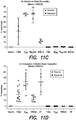
Figures 7-11D are graphic illustrations of % nebulized aerosol and the exposure to a source (S) or receiver (R) wearing no mask or wearing different types of masks including one of the mask of the current application (SF). - It is to be understood that the figures are not drawn to scale. Further, the relation between objects in a figure may not be to scale, and may in fact have a reverse relationship as to size. The figures are intended to bring understanding and clarity to the structure of each object shown, and thus, some features may be exaggerated in order to illustrate a specific feature of a structure.
- For the purposes of this specification and appended claims, unless otherwise indicated, all numbers expressing quantities of ingredients, percentages or proportions of materials, reaction conditions, and other numerical values used in the specification and claims, are to be understood as being modified in all instances by the term "about." Accordingly, unless indicated to the contrary, the numerical parameters set forth in the following specification and attached claims are approximations that may vary depending upon the desired properties sought to be obtained by the present invention. At the very least, each numerical parameter should at least be construed in light of the number of reported significant digits and by applying ordinary rounding techniques.
- Notwithstanding that the numerical ranges and parameters setting forth the broad scope of the invention are approximations, the numerical values set forth in the specific examples are reported as precisely as possible. Any numerical value, however, inherently contains certain errors necessarily resulting from the standard deviation found in their respective testing measurements. Moreover, all ranges disclosed herein are to be understood to encompass any and all subranges subsumed therein. For example, a range of "1 to 10" includes any and all subranges between (and including) the minimum value of 1 and the maximum value of 10, that is, any and all subranges having a minimum value of equal to or greater than 1 and a maximum value of equal to or less than 10, e.g., 5.5 to 10.
- It is noted that, as used in this specification and the appended claims, the singular forms "a," "an," and "the," include plural referents unless expressly and unequivocally limited to one referent. Thus, for example, reference to "a malleable stiffening member" includes one, two or more malleable stiffening members.
- Reference will now be made in detail to certain aspects of the invention, examples of which are illustrated in the accompanying drawings. While the invention will be described in conjunction with the illustrated aspects, it will be understood that they are not intended to limit the invention to those aspects. On the contrary, the invention is intended to cover all alternatives, modifications, and equivalents, which may be included within the invention as defined by the appended claims.
- The headings below are not meant to limit the disclosure in any way; aspects under any one heading may be used in conjunction with aspects under any other heading.
-
Figure 1 illustrates an outside sectional view of thefilter mask 10 in a foldedconfiguration 11 prior to the filter mask being installed upon a wearer's face. In the view shown, this side of thefilter mask 10 would face the outside environment and not touch the wearer's nose, cheeks, jaw and/or chin. Thefilter mask 10 may have application in medical, industrial, domestic, or other circumstances. The mask shown is an N95 respirator, which is a lightweight, nose-and-mouth respirator that provides protection for the wearer from microorganisms (e.g., bacteria, fungi, yeast, molds and viruses). - The
filter mask 10 is generally configured so as to provide a secure fit which reduces or prevents gaps and passage of material between the nostrils and mouth and the surrounding environment except through thefilter material 13. The makeup of thefilter material 13, and thepleating 20 used in connection with thefilter mask 10 will be explained in detail shortly. Thefilter mask 10 has the particular advantage of allowing a secure fit to be created and to be maintained upon installation of thefilter mask 10 on the face with the use of twoear loops - The
filter mask 10 may be constructed of a wide variety of materials and is preferably disposable. Thefilter material 13 used to fabricate thefilter mask 10 may vary according to the particular application of thefilter mask 10. For example, when thefilter mask 10 is to be used in a medical application, such as on members of a surgical team, it is common to use a three layer filter material. However, appropriate filter materials may be of a single or multiple layer design. Multi-layer material may be readily purchased in a precollated form, that is with the three layers already arranged, or the materials may be obtained separately and thefilter material 13 formed in part of the process for forming thefilter mask 10. - Generally, a three or four layer filter medium might include an outer layer of a relatively porous paper-like material which provides durability and resistance against abrasion. The outer layer may also be generally stiffer than the other layers. By using a stiffer outer layer, the effectiveness of the various pleating arrangements is increased. The
pleats 20 are disposed between theupper edge 12 andlower edge 25 and side edges 21 and 29 and may be incorporated in the body of thefilter material 13 to hold thefilter mask 10 in a cup-like shape when installed. The middle layer or layers of the filter material generally contain polyethylene or polypropylene, or other material, which exhibits the proper filtration characteristics. Glass fiber based materials may also have applications as the middle filtration layer. The innermost layer of the filter material to be worn next to or against the face generally comprises a soft material for providing a soft, non-irritating surface against which the facial skin will make contact. - In medical, dental and/or surgical applications, it is generally important that the
filter material 13 also provide a high bacterial filtration efficiency (BFE). The BFE of a filter material is generally determined by the percentage of bacteria, such as Staphylococcus aureus or Bacillus stearothermophilus, that is able to migrate through the filter material under normal conditions. The fewer bacteria which are able to pass through thefilter material 13, the higher the BFE. Of course, a BFE of 100% is desirable; however, efficiencies of as low as 25% are not uncommon among some types of prior art disposable filter masks. However, materials are available which provide BFE's of between 90 and 99%. Thus, in a medical, dental and/or surgical environment it is generally desirable to utilize a filter material having as high a BFE as possible so as to prevent release of nasopharyngeal organisms into the environment. In general, the considerations that provide for a high BFE are the same considerations which provide that a filter material would be desirable in applications in industry and domestic use. For example, a filter material which inhibits the migration of nearly all bacteria would generally also prevent inhalation of dust and dirt particles in industrial applications. Furthermore, it has generally been found that those materials providing a high BFE are often also those materials which provide the least resistance to passage of gases through the filter material. - The passage of gases through the filter material is important in maintaining the comfort of the wearer. It should be realized by one of ordinary skill in the art, however, that many applications might require greater or lesser standards of filtration than is commonly required in the medical environment. Therefore, while filter materials having an efficiency suitable for use with the present application available in the art, the best filter material is of little use if the air inhaled and exhaled by the wearer is allowed to escape the
filter mask 10 without passing through thefilter material 13. Indeed, the lack of a secure fit in the filter masks available in the prior art is important to the design and fabrication of filter masks. Therefore, the present application provides a unique secure fit which reduces or prevents inhaled and exhaled air from leaking around theedges filter mask 10, all while providing a superior fit on a wider range of facial sizes and shapes. The maintenance of such a secure fit greatly improves the overall efficiency of thefilter mask 10. - The structure of the
filter mask 10 is generally prepared as a rectangular piece offlat filter material 13. However, it will be understood by those of ordinary skill in the art that other shapes of the filter mask can be made in order to cover additionally both the eyes, hair, and throat of the user. As such, the present application includes filter masks 10 that cover areas above and beyond simply the nose and mouth of the user. The filter mask may also incorporate any combination of knownfilter mask 10 features, such as visors or shields, sealing films, beard covers, etc. Thefilter mask 10 may be from about 5.5 inches to 7 inches across in length to cover the user's nose and mouth. InFigure 1 , the mask is shown as it would be packaged in its folded and flat configuration, where the outside surface is viewed. - The
filter mask 10 comprises amalleable stiffening member 14 attached to or imbedded in thefilter material 13 at the masksupper edge 12. Themalleable stiffening member 14 is configured to conform thefilter material 13 to at least a nose portion and a cheek portion of the face of the wearer. - A second malleable stiffening
member 24 is attached to or withinlower edge 25 of thefilter material 13, as illustrated inFigure 1 . The second malleable stiffening member is configured to conform the filter material to at least a chin portion and a jaw portion of the face of the wearer. In some aspects, the second malleable member does not include a bend portion. In other aspects, it can include a bend portion that is different from thebend portion 15 in the nose and cheek portion of the mask provided that they can be distinguished (e.g., thebend portion 15 at the nose section can be creased at a larger angle than the optional bend portion in the chin piece). - It should be understood that the use of the term "malleable stiffener" or "malleable stiffening member" herein is meant to include the use of both malleable and flexible stiffeners. It is preferred that the
malleable stiffeners lower edges 25 of thefilter material 13, respectively. Alternatively, themalleable stiffeners lower edges 25 of thefilter material 13. The important property of themalleable stiffeners malleable stiffeners filter mask 10 upon installation. Thefilter mask 10 also hasear loop 30 attached to edges of the mask at attachment points 16 and 22 andear loop 28 to edges of the mask at attachment points 18 and 26 used in donning the mask. In the mask shown inFigure 1 , the ear loops are attached to the outside surface of the mask. However, it will be understood by those of ordinary skill in the art that the loops can be attached to the inside surface of the mask. - Generally, as used herein, the upper portion (33 in
Figure 3 ) of thefilter mask 10 will refer to that portion which contacts the nose and cheek areas of the wearer while the lower portion (40 inFigure 3 ) of thefilter mask 10 will be that portion which is in proximity to the lower jaw and chin of the wearer. Themalleable stiffeners - The
malleable stiffeners - The first
malleable stiffener 14 used for the nose portion of the mask may be from about 3 to 6 inches in length and from about 0.025 or 0.125 or 0.25 or 0.5 inches in height and from about 0.01 or 0.02 or 0.05 or 0.125 or 0.25 inches thick. - The second
malleable stiffener 24 used for the chin portion of the mask may be from about 1.5 to 5 inches in length and from about 0.025 or 0.125 or 0.25 or 0.5 inches in height and from about 0.01 or 0.02 or 0.05 or 0.125 or 0.25 inches thick. The firstmalleable stiffener 14 used in the nose portion can have a length that is larger or the same size as the length of secondmalleable stiffener 24 that is used in the chin portion of the filter mask. Alternatively, the secondmalleable stiffener 24 can be smaller than the firstmalleable stiffener 14. - In one example, a method of wearing a filter mask is provided, the method comprising: providing a filter mask to a wearer and conforming the malleable stiffening member to at least a nose portion and/or a cheek portion of the face of the wearer, the malleable stiffening member having a bend portion indicating at least the inner surface and the nose portion of the filter mask; and securing the filter mask to the wearer's face. The user takes his/her fingertips and applies suitable pressure and bends the malleable stiffening member to conform it to the nose portion and/or cheek portion of the wearer. Thus, the malleable stiffening member is sized, has a length and thickness that allows it to be bent and conform to the nose portion and/or cheek portion of the wearer and a corresponding portion of the mask conforms to the nose portion and/or cheek portion of the wearer as well.
- In another example, a method of wearing a filter mask is provided, the method comprising: providing a filter mask to a wearer; conforming the first malleable stiffening member to at least a nose portion and/or a cheek portion of the face of the wearer, the malleable stiffening member having a bend portion, which is bent, creased, folded, or angled away from the inner surface that indicates at least the outer surface and the nose portion of the filter mask; conforming the second malleable stiffening member to at least a chin portion and/or a jaw portion of the face of the wearer, and securing the filter mask to the wearer's face. The user takes his/her fingertips and applies suitable pressure and bends the first malleable stiffening member to conform it to the nose portion and/or cheek portion of the wearer. Thus, the first malleable stiffening member is sized, has a length and thickness that allows it to be bent and conform to the nose portion and/or cheek portion of the wearer and a corresponding portion of the mask contacting the first malleable stiffening member conforms to the corresponding nose portion and/or cheek portion of the wearer as well. For the second malleable stiffening member, the user takes his/her fingertips and applies suitable pressure and bends the second malleable stiffening member to conform it to the chin portion and/or jaw portion of the wearer. Thus, the second malleable stiffening member is sized, has a length and thickness that allows it to be bent and conform to the chin portion and/or jaw portion of the wearer and a corresponding portion of the mask contacting the second malleable stiffening member conforms to the corresponding chin portion and/or jaw portion of the wearer as well.
- The
malleable stiffening member 14 has abend portion 15 indicating at least the inner surface, outer surface, center and/or the nose portion of the filter mask. The bend portion or crimp includes an angular or rounded shape made by pinching, folding, punching or bending themalleable stiffening member 14 to cause a cavity, indentation, recess, crease, or trough on the inside surface of the mask (not shown) and a projection, peak, protrusion, elevation or ridge on the outside surface of the mask (shown). In some aspacts, thebend portion 15 includes making a ridge or fold by pinching themalleable stiffening member 14 by hand or machine. Although thebend portion 15 is shown generally in the center of themalleable stiffening member 14, it will be understood that thebend portion 15 can be disposed to the left, or right of center. - The
bend portion 15 or crimp may be located by the nose portion of the mask on the outer or inner surface and be angled or crimped in the direction away from the nose so that the user can bend it further for a custom fit around the nose and check area. In this way, the bend portion can be "pre-bent" or "pre-crimped" by the manufacturer. Accordingly, the bend portion will cause the inner surface of the mask that is to be placed against the user's nose to have a cavity, indentation, recess, crease, or trough on the inside surface of the mask and as themalleable stiffening member 14 is further pinched, bent or folded (as shown by the arrows inFigure 2A ), a cavity, indentation, recess, crease, or trough becomes larger to accommodate the nose. In this way, the user will have a visual indication of where the top of the mask is, where the nose section of the mask is and/or where the center of the mask is for those examples where the bend portion is disposed within the center or generally within the center of themalleable stiffening member 14. In some examples, thebend portion 15 allows the user to identify the outside of the mask, the inside of the mask, top of the mask, and/or center of the mask. In some examples, thebend portion 15 is packaged (not shown) at least partially bent so that the cavity, indentation, recess, crease, or trough is visible on the interior of the mask. - The
bend portion 15 or crimp is typically formed from the same material as the malleable stiffening member. However, the same or different material may be used as long as the bend portion will cause a crease or fold in the filter material and allow the user to identify the top, center, inside and/or outside of the mask. The bend portion may be formed from any suitable material, such as an elastic material (e.g. a polymer), inelastic material, a nonwoven, knit, ribbon, cloth, wire, metal or the like. - In some examples, the bend portion may be bent before use by the manufacturer by about 1 to about 5 degrees, by about 1 to about 10 degrees, or by about 5 to about 20 degrees. In some examples, the bend portion may be bent before use by the manufacturer so that the bend portion projects out of the inner or outer surface of the mask by about 0.25 mm to about 0.5mm, or by about 1 mm to about 5 mm or by about 1 mm to about 10mm or by about 5 mm to about 20 mm, or by about 10 mm to about 30 mm or by about 35 mm to about 60 mm. In some examples, the bend portion is designed for easy bending around the ridge of the nose. In some embodiments, the bend portion, like the malleable stiffening member, may be substantially deformable so that a wearer is able to bend, pinch or fold the bend portion and/or the malleable stiffening member between two or more fingers when gripping it as it is put around the ridge of the nose.
- The
bend portion 15, since it provides space between adjacent masks, allows thefilter mask 10 to be stacked for easy packaging and dispensing of a plurality of masks. In some examples, a stack of filter masks is provided comprising: a plurality of filter masks, each filter mask comprising a filter material having an inner surface to be worn against a wearer's face, and an outer surface, the filter material comprising at least one pleat for folding and unfolding the filter material such that when folded the filter material assumes a generally flat storage configuration having upper, lower and side edges and such that when unfolded the filter material forms a mask configured to cover the nose and mouth of the wearer, the at least one pleat disposed between the upper, and lower edges and configured to fit over a chin of the wearer when unfolded; a malleable stiffening member attached to or within the filter material proximate to the upper edge, the malleable stiffening member configured to conform the filter material to at least a nose portion and a cheek portion of the face of the wearer, the malleable stiffening member having a bend portion indicating at least the outer surface and the nose portion of the filter mask; a securing means for securing the filter material to the wearer's face; and wherein the masks are positioned in a nestled relation to one another (e.g., masks that are close or one on top of the other in the package), the inner surface of at least one mask being apposed to the outside surface of an adjacent mask, thereby forming a stack. -
Figure 2A illustrates a top side view of the malleable stiffening member 31 (e.g., metal strip) having a bend portion shown as a crimp or crease. The bend portion has a projection, peak, protrusion, elevation orridge 32A that extends out and is visible on the outside surface of the mask (not shown). The bend portion has a cavity, indentation, recess, crease, ortrough 32B on the inside of the mask that is visible on the inside surface of the mask. The stiffeningmember 31 would have this configuration when attached to the mask. The mask would be in a flat and/or folded configuration. In the embodiment, shown the bend portion, like themalleable stiffening member 31, may be substantially deformable so that a wearer is able to bend or fold the bend portion and/or the malleable stiffening member in the direction of the arrows shown using two or more fingers when gripping it as it is put around the ridge of the nose. - By employing a bend portion in the
malleable stiffening member 31, which is placed in the center of the filter mask, the wearer will see a projection, peak, protrusion, elevation, or ridge or other marker visible on the outside surface of the mask, or a cavity, indentation, recess, crease, or trough or other marker visible on the inside surface of the mask and know where the top inside or outside, and/or center of the mask is and where the nose portion of the mask is to be placed on the face. It will be understood by those of ordinary skill in the art that the bend portion can be any shape (e.g., regular, irregular, symmetrical or asymmetrical shape). - In some examples, the bend portion causes a projection, peak, protrusion, elevation, or ridge or other marker on the top front, outside and/or center portion of the mask so that the wearer will know these portions of the mask and know the right side of the mask should be facing the outside environment and not the wearer's nose or face. In this way, the filter mask of the present application reduces the risk that the wearer will wear the mask incorrectly.
-
Figure 2B illustrates a top view of themalleable stiffening member 31 having a bend portion shown as it would start to bend around the nose if the filter mask (not shown) was unfolded. The bend portion has a projection, peak, protrusion, elevation orridge 32A that extends out and is visible on the outside surface of the mask (not shown). The projection increases as themalleable stiffening member 31 is further bent or pinched. The bend portion has a cavity, indentation, recess, crease, ortrough 32B on the inside of the mask that is visible on the inside surface of the mask and gets bigger as the malleable stiffening member is further bent, pinched or folded. The stiffeningmember 31 would have this configuration when attached to or in the unfolded mask. In the example, shown the bend portion, like themalleable stiffening member 31 may be substantially deformable so that a wearer is able to bend or fold the bend portion and/or the malleable stiffening member using two or more fingers when gripping it as it is put around the ridge of the nose. - In some examples, the bend is in a vertical direction relative to the one or more pleats. In some examples, the bend portion 32 is crimped, bent, creased, folded, or angled toward the inner surface or outer surface of the filter mask by about 1 to 10 degrees or by 0.5 mm to about 50 mm. For example, the crimp can be from 1 mm, 10 mm, 15 mm, 20 mm, 30 mm, 35 mm, 40 mm, 45 mm, 50 mm, 55 mm, 60 mm, or 65 mm.
- The filter mask may be attached to the user by a securing means that can attach the mask to the user. For example, the securing means may be a pair of manual tie straps that are wrapped around the head of the user and are connected to one another, or the securing means may be ear loops (28 and 30 in
Figure 1 ), elastic bands wrapped around the head of the user, a hook and loop type fastener arrangement (e.g. VELCRO® fasteners), or a connection directly attaching the face mask to a hair cap. - In some examples, the ear loops (28 and 30 in
Figure 1 ) can be attached to the inner or outer surface of the mask atupper edges lower edges - The loop may be formed from any suitable material, such as an elastic material (e.g. a polymer), inelastic material, a nonwoven, knit, ribbon, cloth, wire, and so forth. As used herein, the term "elastic" refers to the ability of a material to recover its size and shape after deformation. As used herein, the term "inelastic" refers to the inability of a material to recover its size and shape after deformation. In some embodiments, the loop is formed from the same material selected to form the outside surface of the mask. The loop may be bonded or otherwise affixed to the outside surface or inside surface of the mask. Examples of suitable techniques include adhesive bonding, thermal bonding, stitching, and so forth. As used herein, the term "adhesive" refers to the property of any material that allows the material to bond together substrates by surface attachment.
- The loop is generally sized and positioned to facilitate gripping by a wearer, both prior to, during, and after donning. The
loop 30 may be more or less than about 80 mm (0.08 m) in length as measured from thefirst end 16 to thesecond end 22 along the length of the loop. In other examples, theloop 30 may be less than about 60 mm (0.06 m) in length. In yet other embodiments, theloop 30 may be less than about 40 mm (0.04 m) in length. Where, in some embodiments, the loop is formed from an elastic material, the loop may have a fully extended length of 200 mm (0.200 m) or more. In some examples, the loop is from about 4 to 10 inches in length. - In some examples, the loop generally extends inwardly from the outside surface or inside surface a sufficient distance so that the wearer of the mask may grip the loop between two or more fingers of a single hand. In some examples, the loop may extend outwardly from the inside or outside surface at least 5 mm (0.005 m). In other embodiments, the loop may extend outwardly from the outside or inside surface at least about 8 mm (0.008 m). In yet other examples, the loop may extend outwardly from the outside or inside surface at least about 10 mm (0.01 m) from the outside surface.
-
Figure 3 illustrates a cross-sectional view of a filter mask in the unfolded position installed upon a wearer's face. Thefilter mask 34 may have applications in medical, industrial, domestic, or other circumstances. Thefilter mask 34 is generally configured so as to provide a secure fit which prevents passage of any material between the nostrils and mouth and the surrounding environment except through thefilter material 36. - The
filter material 36 comprises one or more pleats 38 (shown in the unfolded position). The one or more pleats are disposed between at least the upper, lower, and/or side edges of the mask. - The
filter mask 34 comprises in itsupper section 33, an uppermalleable stiffener 35, which when pinched, folded or twisted pulls thefilter material 36 including its top and side edges to be held against the nose and cheeks while the lowermalleable stiffener 42 in thelower section 40 of the filter mask, which when pinched, twisted or folded pulls the side and lower edges into the side of the face and lower jaw area to provide a secure, comfortable and custom fit. Furthermore, it can also be seen that thepleat 38 allows the creation of a pocket-like shape or chamber by which the inner surface of thefilter material 36 is held tightly against the lower jaw area of the wearer. The upper and lower malleable stiffeners (35 and 42) increase the secure fit formed around the nose and cheek area and the chin and jaw portion of the face of the wearer. -
Figure 4 illustrates a perspective view of afilter mask 44 installed upon a wearer's face. Theouter surface 58 of thefilter mask 44 is shown facing the outside environment that thewearer 64 is exposed to. Thefilter mask 44 is shown in its unfolded position and secured to the wearer's face to provide the secure and comfortable fit by securing the ear loops (one shown as 62) around the wearer's ears. The ear loops are preferably formed of elastic such that they will secure thefilter mask 44 in the proper position on the wearer's face. Use of elastic ear loops allows thefilter mask 44 to be easily installed by the wearer and avoids the difficulty of tying a string tie behind the head. Furthermore, since the ear loops are elastic, there is not the risk of the ear loops becoming untied at an inopportune moment which accompanies the use of ordinary tie strings. Furthermore, the elasticity of the ear loops may be chosen so as to allow thefilter mask 44 to be easily repositioned on the face while only using one hand. - The
filter mask 44 comprises one or more pleats (shown in the unfolded position are three pleats that have been unfolded 48, 50 and 52). The one or more pleats are disposed between at least the upper, lower, and/or side edges of the mask. As used herein, the term "pleat" refers to a relatively flat double-fold formed in thefilter mask 44 when thefilter mask 20 is in the flat storage configuration (as illustrated inFigure 1 ). The pleats in the filter material can be any known in the art and include, for example, Z shaped pleats, standard pleats, omega pleats, secondary pleats, reverse pleats or the like. - The one or more pleats are disposed between the upper, lower and side edges (60) of the mask. It will be understood by those of ordinary skill in the art that the mask may have one, two, three, four, five, six, seven, eight or more pleats, each of which can be the same or different sizes and/or shapes.
- The
filter mask 44 comprises in its upper section, an uppermalleable stiffener 46, which when pinched, folded or twisted pulls the filter material including its top and side edges against the nose and cheeks. The filter mask also comprises lowermalleable stiffener 54 in the lower section of the filter mask, which when pinched, folded or twisted pulls the side and lower edges into the side of the face and lower jaw area to provide a secure facial fit. Furthermore, it can also be seen that thepleat - By properly positioning the ear loops, the one or more pleats, and pinching, bending, folding or twisting the malleable stiffeners against the nose, cheek, chin and/or jaw areas upon installation of the filter mask, a secure fit is provided not only along the upper and lower
malleable stiffeners filter mask 44 which contact the cheeks. This is due to the effect of the tension exerted because of the cooperation of the pleats, malleable stiffener(s) and the ear loops. Furthermore, thefilter mask 44 still allows for normal speech without significant difficulty while maintaining a secure fit. -
Figure 5 illustrates the inner surface 68 of a filter mask that the wearer would place against his/her face. The mask is shown in the unfolded or partially unfolded position. The uppermalleable stiffener 67 imbedded or attached to the mask has been folded, crimped, pinched, bent, creased, and/or angled around the wearer's nose and/or cheek area and causes a cavity 66 in the filter material that conforms and pulls it closer to a portion of the nose and/or cheek. The lowermalleable stiffener 70 imbedded or attached to the mask has been crimped, bent, creased, folded, pinched, and/or angled around or under the wearer's chin and/or jaw area and causes acavity 69 in the filter material that conforms and pulls it closer to a portion of the wearer's chin and/or jaw area. In some embodiments, thecavity 69 will be located under the chin so that the user can rest it on it. The mask provides a secure and comfortable fit for the user by simply pinching the malleable stiffeners. It will be understood by those of ordinary skill in the art that the cavities in the inside of themask 66 and 69 can be aligned vertically with each other or be substantially parallel to each other so thatprojection 66 and 69 line up. -
Figure 6 illustrates theouter surface 73 of the filter mask installed upon a wearer's face. The mask is shown in the unfolded or partially unfolded position. The uppermalleable stiffener 71 imbedded or attached to the mask has been folded, crimped, pinched, bent, creased, and/or angled around the wearer's nose and/or cheek area and causes aprojection 72 in the filter material that conforms it to a portion of the nose and/or cheek. The lowermalleable stiffener 74 imbedded or attached to the mask has been crimped, bent, creased, folded, pinched, and/or angled around or under the wearer's chin and/or jaw area and causes aprojection 75 in the filter material that conforms to a portion of the wearer's chin and/or jaw area. In some examples, theprojection 75 will be located under the chin so that the user can rest it on it. The mask provides a secure and comfortable fit for the user by simply pinching the malleable stiffeners. In this way, the mask reduces leakage of material around the top, bottom and edges of the masks. It will be understood by those of ordinary skill in the art that the projections in the outside of themask projection - In some examples, individuals who wear eyeglasses also are plagued by the problem of fogging of their glasses due to condensation of warn, vapor laden exhaled air on the colder surface of their eyeglasses. Ensuring a secure fit along the upper edge of the filter mask helps to reduce fogging of eyeglasses due to the condensation of vapor laden air.
- In some examples, for easy grasping, the filter mask may be thermally molded or heat set to increase stiffness. In other embodiments, binder chemicals may be added to the materials prior to formation of the mask. The filter mask can be disposable and/or for single use.
- The filter mask may be formed from a variety of materials and fabrics, such as woven reusable fabrics and nonwoven disposable fabrics or webs. As used herein, the term "nonwoven fabric" or "nonwoven web" or "nonwoven material" means a web having a structure of individual fibers or threads that are randomly interlaid, but not in an identifiable manner or pattern as in a knitted fabric. Nonwoven fabrics or webs have been formed from many processes, for example, meltblowing processes, spunbonding processes, and bonded carded web processes.
- As used herein, the term "spunbond" or "spunbond fibers" or "spunbonded fibers" refers to small diameter fibers that are formed by extruding molten thermoplastic material as filaments from a plurality of fine, usually circular capillaries of a spinneret with the diameter of the extruded filaments then being rapidly reduced, for example, as in
U.S. Pat. No. 4,340,563 to Appel et al. , andU.S. Pat. No. 3,692,618 to Dorschner et al. ,U.S. Pat. No. 3,802,817 to Matsuki et al. ,U.S. Pat. Nos. 3,338,992 and3,341,394 to Kinney ,U.S. Pat. No. 3,502,763 to Hartman , andU.S. Pat. No. 3,542,615 to Dobo et al. - As used herein, the term "meltblown" or "meltblown fibers" means fibers formed by extruding a molten thermoplastic material through a plurality of fine, usually circular, die capillaries as molten threads or filaments into converging high velocity, usually hot, gas (e.g. air) streams that attenuate the filaments of molten thermoplastic material to reduce their diameter, which may be to microfiber diameter. Thereafter, the meltblown fibers are carried by the high velocity gas stream and are deposited on a collecting surface to form a web of randomly disbursed meltblown fibers. Such a process is disclosed, for example, in
U.S. Pat. No. 3,849,241 to Butin et al. - The filter mask may be formed from a single layer of material or a composite of multiple layers. In the case of multiple layers, the layers are generally positioned in a juxtaposed or surface-to-surface relationship and all or a portion of the layers may be bound to adjacent layers. The multiple layers of a composite may be joined to form a multilayer laminate by various methods, including but not limited to adhesive bonding, thermal bonding, or ultrasonic bonding.
- One composite material suitable for use with the present application is a spunbond/meltblown/spunbond (SMS) laminate. An SMS laminate may be made by sequentially depositing onto a moving forming belt first a spunbond fabric layer, then a meltblown fabric layer and last another spunbond layer and then bonding the laminate in a manner described below. Alternatively, the fabric layers may be made individually, collected in rolls, and combined in a separate bonding step. Multilayer laminates may have multiple meltblown layers or multiple spunbond layers in many different configurations and may include materials other than nonwovens. Examples of such other materials include wovens, films, foam/film laminates and combinations thereof, for example, a spunbond/film/spunbond (SFS) laminate. Examples of other composite materials suitable for use in the present invention include, but are not limited to, those described in
U.S. Pat. No. 4,041,203 to Brock et al. ,U.S. Pat. No. 5,169,706 to Collier, et al. ,U.S. Pat. No. 5,145,727 to Potts et al. ,U.S. Pat. No. 5,178,931 to Perkins et al. ,U.S. Pat. No. 4,374,888 to Bornslaeqer , andU.S. Pat. No. 5,188,885 to Timmons et al. - The filter mask of the present application may include a layer of material, for example, a nonwoven material, suitable for filtration. The filtration material may be made from a meltblown nonwoven web and, may be subject to electret treating. As used herein, the term "electret" or "electret treating" refers to a treatment that imparts a charge to a dielectric material, such as a polyolefin. The charge includes layers of positive or negative charges trapped at or near the surface of the polymer, or charge clouds stored in the bulk of the polymer. The charge also includes polarization charges that are frozen in alignment of the dipoles of the molecules. Methods of subjecting a material to electret treating are well known by those skilled in the art. These methods include, for example, thermal, liquid-contact, electron beam, and corona discharge methods. One particular technique of subjecting a material to electret treating is disclosed in
U.S. Pat. No. 5,401,466 . This technique involves subjecting a material to a pair of electrical fields wherein the electrical fields have opposite polarities. Electret treatment results in a charge being applied to the filtration medium that further increases filtration efficiency by drawing particles to be filtered toward the filter by virtue of their electrical charge. Electret treatment can be carried out by a number of different techniques. One technique is described inU.S. Pat. No. 5,401,446 to Tsai . Other methods of electret treatment are known in the art, such as that described inU.S. Pat. No. 4,215,682 to Kubik et al. ,U.S. Pat. No. 4,375,718 to Wadsworth ,U.S. Pat. No. 4,592,815 to Nakao andU.S. Pat. No. 4,874,659 to Ando . - Alternatively, the mask may include a layer of expanded polytetrafluoroethylene (PTFE) membrane for filtration, such as those manufactured by W. L. Gore & Associates. A more complete description of the construction and operation of such materials can be found in
U.S. Pat. No. 3,953,566 to Gore andU.S. Pat. No. 4,187,390 to Gore . - In some examples, the filter mask comprises one or more layers individually or combined made of medical grade tissue, spun bound polypropylene, cellulose material, meltblown polypropylene, spun bound high density polyethylene, and/or low density polyethylene.
- In some examples, one or more layers of the mask may be impervious or substantially impervious to liquid (e.g., spun bound polypropylene, and/or meltblown polypropylene layer(s)), which may cause liquid to bead on one or more surfaces or layers of the mask.
- In some examples, the filter mask can be made by providing the filter material and inserting or attaching the malleable stiffening members to the mask, where at least one malleable stiffening member is partially bent, crimped, creased, folded, and/or angled and attached to or in the nose portion of the mask, either on the inside of the mask or outside of it and then attaching a second malleable stiffening member to the lower portion of the mask for the chin and/or jaw area; and attaching securing members to the mask, either on the inside of the mask or outside of it.
- In some examples, a method of making a filter mask having a bend portion is provided, the method comprising providing a filter material having an inner surface to be worn against a wearer's face, the filter material comprising at least one pleat for folding and unfolding the filter material such that when folded the filter material assumes a generally flat storage configuration having upper, lower and side edges and such that when unfolded the filter material forms a mask configured to cover the nose and mouth of the wearer, the at least one pleat disposed between at least the upper and lower edges and configured to fit over a chin of the wearer when unfolded; a malleable stiffening member attached to or within the filter material proximate to the upper edge, the malleable stiffening member configured to conform the filter material to at least a nose portion and a cheek portion of the face of the wearer; bending, folding, creasing, crimping, or angling the malleable stiffening member, and inserting it or attaching it to at least the inner surface and the nose portion of the filter mask to indicate at least the inner surface and the nose portion of the filter mask; and attaching a securing means to the filter material.
- In some examples, the bend portion is pinched, crimped, bent, creased, folded, or angled toward the inner surface or outer surface of the filter mask by about 1 to 10 degrees or by 1 mm to about 20 mm by hand or machine, before, during or after it is attached or imbedded in the mask. These include crimping machines having stops, posts, or the like that allow the bend portion to be formed.
- In some examples, the filter mask of the current application can be used with an external filter in the environment, ventilation system (e.g., intake and/or exhaust ventilation), negative pressure rooms or the like. For example, a negative pressure room, in addition to the filter mask worn on the user and/or receiver, may prevent further contamination of individuals (e.g., patients, healthcare workers, visitors, etc.). A negative pressure room includes a ventilation system designed so that air flows from the corridors, or any adjacent area, into the negative pressure room, reducing the risk that contaminated air escapes from the negative pressure room to other parts of the facility. The air in the negative pressure room, may be filtered before it is exhausted.
- Having now generally described the invention, the same may be more readily understood through the following reference to the following examples, which are provided by way of illustration and are not intended to limit the present invention as defined by the claims.
- This study addresses the effects of improved mask fit, through both improved mannequin breathing models as well as through various mask fit methods, i.e. tight mask, natural fitting mask, and/or SecureFit mask. The SecureFit mask of the current application contains a malleable stiffening member (e.g., metal strip) in the nose portion and the chin portion of the filter mask, the user can pinch the malleable stiffening members to obtain a secure and comfortable fit to the mask and, therefore, have the mask custom fit to his/her face. SecureFit achieves better results than a Standard mask "natural fit" (SMnat) while negating the need for an unnaturally (and typically unachievable) tight fit (TSM). When the source wears the mask of the current application (SecureFit) the risk of exposure to the receiver decreases.
- The source includes a subject who generates or expels aerosol in the course of breathing, coughing, sneezing, etc. A receiver includes a subject who inhales or receives such aerosol on the surface of the face and/or body. The aerosol includes a suspension of dry or liquid microscopic particles, which can include, for example, bacteria, fungi, yeast, molds and/or viruses, or the like. These are contaminants of the aerosol.
- It was found that the TSM worn on the receiver of the aerosol from the source protects the wearer better than SMnat. On the source, the TSM captures more particles from the wearer (source) than the SMnat. This test was done under negative pressure room simulation. The TSM and the SF protect the receiver (wearer) with tighter confidence intervals than do the SMnat. SF unexpectedly captures/contains more particles from the wearer (source) than either the TSM or the SMnat.
- Purpose: To test the effects of improved fit and study the importance of room ventilation on source control protection by comparing extraction and air circulation models. Methods: Two mannequin heads were placed in a chamber allowing 6 air extractions/hour to simulate patient (source) and health care worker (receiver) interaction. The source exhaled radioactive aerosols and a filter was attached to the receiver to quantify inhaled exposure defined as % nebulized aerosol. The mannequin heads were ventilated using tidal breathing patterns. N95 respirators and surgical masks were tested on both. Experiments were repeated in a chamber with circulating airflow at 150 cfm. It was found that placing any mask on the head significantly reduces receiver exposure. On the receiver, only Vaseline sealed N95 respirators come close (
Figure 11A ). Maximum exposure was reduced in air circulation model. Surgical masks on the source can be as effective as receiver protection with the N95 masks (Figure 11B ). Mask filtration at the source N95>TSM>SMnat, reduce exposure and are not simple function of mask filtration (Figure 11C ). Wearing the mask is significant only when the source wears the mask. Receiver filtration is less important as compared to when a source wears a mask (Figure 11D ). - Changing the fit of masks on the source confirmed that source control protection remained superior to receiver control protection in the setting of air extraction. Source control protection is enhanced by environmental air extraction (e.g., negative pressure, vented air, filtered air, etc.) because particles are deflected away from the receiver and removed from the environment. In the standard room air mixing model, a surgical mask on the source was found to offer comparable protection to the N95 respirator on the receiver.
- When no masks are used on either source or receiver, maximum exposure (MaxEx) to receiver is achieved. When the source wears a mask (left side of
Figure 10 ), exposure to the receiver is reduced. That exposure to receiver is the least when the source wears a SecureFit mask (S-SF). Exposure is greatest when the source wears a standard mask (S-SMnat). When the receiver wears a mask, the greatest exposure results from the standard surgical mask (R-SMnat). SecureFit (R-SF) provides equivalent protection to the Tight Mask (R-TSM) when worn by the receiver. These results are illustrated inFigure 10 (Misty Neb IM Cough Data). - When no masks are worn on either source or receiver, maximum exposure (MaxEx) to receiver is achieved. When masks are worn at the source, SecureFit results in less exposure to the receiver than the Standard Mask (S-SMnat). When masks are worn by the receiver, SecureFit (R-SF) results in less exposure to wearer (receiver) than does a Standard Mask (R-SMnat). The results are shown in
Figures 7-9 . InFigure 8 , SecureFit captures or confines more of the exhaled aerosolized particles, which gives further protection to the user and the receiver. - In some embodiments, the filter mask is worn by a source and prevents contaminants from infecting a receiver who is not wearing a filter mask. In some embodiments, the filter mask is worn by a source and prevents contaminants from infecting a receiver who is also wearing a filter mask.
- It will be apparent to those skilled in the art that various modifications and variations can be made to various embodiments described herein without departing from the spirit or scope of the teachings herein. Thus, it is intended that various embodiments cover other modifications and variations of various embodiments within the scope of the present teachings.
Claims (14)
- A filter mask (10) comprising: a filter material (13) having an inner surface to be worn against a wearer's face, the filter material comprising at least one pleat (20) for folding and unfolding the filter material such that when folded the filter material assumes a generally flat storage configuration having upper (12), lower (25) and side (21, 29) edges and such that when unfolded the filter material forms a mask configured to cover the nose and mouth of the wearer, the at least one pleat (20) disposed between at least the upper (12) and lower (25) edges and configured to fit over a chin of the wearer when unfolded; (i) an upper malleable stiffening member (14) attached to or within the filter material proximate to the upper edge, the upper malleable stiffening member (14) configured to conform the filter material to at least a nose portion and a cheek portion of the face of the wearer, the upper malleable stiffening member (14) having a bend portion (15) indicating at least the inner surface and the nose portion of the filter mask, and a means for securing the filter material to the wearer's face comprising first (28) and second (30) ear loops each having a first end (16) connected adjacent the upper edge (12) of the filter mask and a second end (22) connected adjacent the lower edge (25) of the filter mask, the first (28) and second (30) ear loops being oppositely disposed relative to one another, characterized in that the filter mask (10) further comprises (ii) a lower malleable stiffening member (24) attached to or within the filter material proximate to the lower edge (25), the lower malleable stiffening member (24) configured to conform the filter material to at least a chin portion and a jaw portion of the face of the wearer, wherein the upper malleable stiffening member (14) is longer than the lower malleable stiffening member (24).
- A filter mask (10) according to claim 1, wherein the lower malleable stiffening member (24) has a bend portion, wherein the bend portion indicates an outer surface of the mask.
- A filter mask (10) according to claim 2, wherein the lower malleable stiffening member (24) is configured to be pinched under the chin or jaw area to form a projection.
- A filter mask (10) according to claim 1, wherein (i) the means for securing comprises a pair of ear loops (28, 30) attached to the filter material and the bend portion which is crimped, bent, creased, folded, or angled toward the inner surface or outer surface of the filter mask by about 1 to 10 degrees or by 1 mm to about 50 mm; (ii) the filter material (13) comprises an outer layer, an inner layer and a middle layer of a material having a high filtration efficiency; (iii) the upper malleable stiffening member (14) is embedded within the filter material proximate to the upper edge (12) or the filter mask (10) is used by a health care worker; (iv) the at least one pleat (20) disposed between the upper (12), lower (25) and side (21, 29) edges provides a breathing chamber when unfolded; (v) the filter mask (10) comprises at least three pleats (20); (vi) the filter mask (10) is worn by a receiver of aerosolized particles and/or by a source of aerosolized particles; (vii) the filter mask (10) is used in a room comprising vented air flow; (viii) the filter mask (10) is worn by a source and prevents contaminants from infecting a receiver who is not wearing a filter mask; or (ix) the filter mask (10) is worn by a source and prevents contaminants from infecting a receiver who is also wearing a filter mask.
- A filter mask (10) according to claim 4, wherein the ear loops (28, 30) are formed of an elastic material and the bend portion is bent by about 1 mm to about 20 mm.
- A filter mask (10) according to claim 4, wherein the lower malleable stiffening member (24) after bending, crimping or pinching causes a recess on the inner surface that pulls the filter material taut against the chin and/or jaw portion of the face.
- A filter mask (10) according to claim 1, wherein the upper malleable stiffening member (14) comprises a length between about 3 inches and about 6 inches and the lower malleable stiffening member (24) comprises a length between about 1.5 inches and about 5 inches.
- A stack of filter masks according to claim 1 comprising: a plurality of filter masks, each filter mask comprising an outer surface positioned opposite the inner surface, wherein the masks are positioned in a nestled relation to one another, the inner surface of at least one mask being opposed to the outside surface of an adjacent mask, thereby forming a stack.
- A stack of filter masks according to claim 8, wherein the bend portion of each mask is adapted to maintain a distance between adjacent masks.
- A stack of filter masks according to claim 8, wherein the bend portion is bent by about 1 to 10 degrees.
- A stack of filter masks according to claim 8, wherein the bend portion is bent by about 35 to 50 mm.
- A method of wearing a filter mask (44) according to claim 1, the method comprising: providing a filter mask of claim 1 to a wearer (64); conforming the upper malleable stiffening member (46) to at least a nose portion and a cheek portion of the face of the wearer, the first malleable stiffening member (46) having a bend portion, which is bent, creased, folded, or angled away from the inner surface that indicates at least the outer surface and the nose portion of the filter mask; conforming the lower malleable stiffening member (54) to at least a chin portion and a jaw portion of the face of the wearer (64), and securing the filter mask to the wearer's face.
- A method of wearing a filter mask (44) according to claim 12, wherein the filter mask is worn by a source and prevents contaminants from infecting a receiver who is not wearing a filter mask.
- A method of wearing a filter mask (44) according to claim 12, wherein the filter mask is worn by a source and prevents contaminants from infecting a receiver who is also wearing a filter mask.
Applications Claiming Priority (2)
| Application Number | Priority Date | Filing Date | Title |
|---|---|---|---|
| US37858510P | 2010-08-31 | 2010-08-31 | |
| PCT/US2011/049690 WO2012030798A1 (en) | 2010-08-31 | 2011-08-30 | A filter mask having one or more malleable stiffening members |
Publications (3)
| Publication Number | Publication Date |
|---|---|
| EP2611315A1 EP2611315A1 (en) | 2013-07-10 |
| EP2611315A4 EP2611315A4 (en) | 2014-06-25 |
| EP2611315B1 true EP2611315B1 (en) | 2017-06-07 |
Family
ID=45773233
Family Applications (1)
| Application Number | Title | Priority Date | Filing Date |
|---|---|---|---|
| EP11822474.0A Active EP2611315B1 (en) | 2010-08-31 | 2011-08-30 | A filter mask having one or more malleable stiffening members |
Country Status (4)
| Country | Link |
|---|---|
| US (3) | US10668308B2 (en) |
| EP (1) | EP2611315B1 (en) |
| CA (1) | CA2809834C (en) |
| WO (1) | WO2012030798A1 (en) |
Cited By (1)
| Publication number | Priority date | Publication date | Assignee | Title |
|---|---|---|---|---|
| WO2022220811A1 (en) * | 2021-04-13 | 2022-10-20 | Hewlett-Packard Development Company, L.P. | Porous articles formed of molded fibers |
Families Citing this family (58)
| Publication number | Priority date | Publication date | Assignee | Title |
|---|---|---|---|---|
| US20080271739A1 (en) | 2007-05-03 | 2008-11-06 | 3M Innovative Properties Company | Maintenance-free respirator that has concave portions on opposing sides of mask top section |
| US9770611B2 (en) | 2007-05-03 | 2017-09-26 | 3M Innovative Properties Company | Maintenance-free anti-fog respirator |
| EP2611315B1 (en) * | 2010-08-31 | 2017-06-07 | Crosstex International, Inc. | A filter mask having one or more malleable stiffening members |
| WO2012061831A1 (en) | 2010-11-05 | 2012-05-10 | Salutaris Llp | Ergonomic protective air filtration devices and methods for manufacturing the same |
| US20160015098A1 (en) * | 2013-03-15 | 2016-01-21 | Matthew CONLON | A facemask having one or more nanofiber layers |
| CN103734939B (en) * | 2014-01-27 | 2014-12-31 | 山东爱地高分子材料有限公司 | High-heat-conducting durable mask |
| CN104399201B (en) * | 2014-11-06 | 2017-12-01 | 张庆华 | A kind of nose air filter for wearing non-contact face portion |
| WO2016089793A1 (en) * | 2014-12-02 | 2016-06-09 | Prestige Ameritech, Ltd | Fitted face mask |
| GB201421617D0 (en) | 2014-12-04 | 2015-01-21 | 3M Innovative Properties Co | Respirator tab |
| GB201421616D0 (en) * | 2014-12-04 | 2015-01-21 | 3M Innovative Properties Co | Respirator headband |
| GB201421620D0 (en) * | 2014-12-04 | 2015-01-21 | 3M Innovative Properties Co | Flat-fold respirator |
| US11219559B2 (en) * | 2015-04-07 | 2022-01-11 | Ent Solutions Group, Llc | Nasal drip pad |
| USD782029S1 (en) * | 2015-12-18 | 2017-03-21 | Phyllis Kuhn | Mask |
| US20170231297A1 (en) * | 2016-02-17 | 2017-08-17 | Rosemary German | Face and chin guard for infants |
| JP6374432B2 (en) * | 2016-04-15 | 2018-08-15 | ユニ・チャーム株式会社 | Disposable mask |
| USD872256S1 (en) * | 2016-08-17 | 2020-01-07 | Masgick, Inc. | Strapless collapsible respiratory mask |
| JP2018044269A (en) * | 2016-09-16 | 2018-03-22 | 三井化学株式会社 | mask |
| USD849928S1 (en) * | 2017-05-15 | 2019-05-28 | Jonathan Grover | Facemask |
| JP7186213B2 (en) | 2017-07-14 | 2022-12-08 | スリーエム イノベイティブ プロパティズ カンパニー | Adapter for conveying multiple liquid streams |
| USD854144S1 (en) * | 2017-09-05 | 2019-07-16 | Prestige Ameritech, Ltd. | Ear loop mask |
| CN107485080B (en) * | 2017-09-13 | 2020-02-07 | 北京小米移动软件有限公司 | Gauze mask |
| DE102018002343A1 (en) * | 2018-03-21 | 2019-09-26 | Dräger Safety AG & Co. KGaA | Half-mask respirator |
| DE102018009982A1 (en) * | 2018-12-21 | 2020-06-25 | Dräger Safety AG & Co. KGaA | Respiratory half mask and method for producing a respiratory half mask |
| US10835704B1 (en) | 2019-05-15 | 2020-11-17 | Applied Research Associates, Inc. | Reusable respiratory protection device |
| RU2762679C1 (en) | 2019-11-28 | 2021-12-21 | Чинь-Лун ЯН | Face mask with support strip |
| CN212088206U (en) * | 2020-02-04 | 2020-12-08 | 杨金龙 | Gauze mask |
| CN111317897A (en) * | 2020-03-20 | 2020-06-23 | 徐栋梁 | Infectious disease isolation and killing system for respiratory system |
| WO2021195354A1 (en) * | 2020-03-26 | 2021-09-30 | Alexander Werjefelt | Pathogen protection device |
| US11766079B2 (en) | 2020-03-30 | 2023-09-26 | Under Armour, Inc. | Face mask and method of making the same |
| JP7648046B2 (en) * | 2020-04-20 | 2025-03-18 | サンコ テキスタイル イスレットメレリ サン ベ ティク エーエス | Respiratory mask and method of manufacturing same |
| CN111329162A (en) * | 2020-04-29 | 2020-06-26 | 苏州卫生职业技术学院 | Face mask capable of shielding chin |
| US11052269B1 (en) * | 2020-05-01 | 2021-07-06 | II Michael D. Greenway | Protective face masks |
| EP3909449A1 (en) * | 2020-05-11 | 2021-11-17 | Bisaf Spolka Z Ograniczona Odpowiedzialnoscia | Protective filtering half mask |
| EP3915647A1 (en) * | 2020-05-28 | 2021-12-01 | Eurofilters Holding N.V. | Respirator mask |
| TWM620381U (en) * | 2020-05-29 | 2021-12-01 | 鴻林堂生物科技股份有限公司 | A mask structure |
| US11284654B2 (en) | 2020-06-10 | 2022-03-29 | Under Armour, Inc. | Breathable face mask |
| USD986408S1 (en) * | 2020-06-12 | 2023-05-16 | Beijing Naton Medical Technology Holdings Co., Ltd. | Mask |
| US12161177B2 (en) * | 2020-06-26 | 2024-12-10 | Ningbo Troika Science & Technology Company Limited | Flexible mask with adjustable strap |
| US12186647B2 (en) | 2020-08-24 | 2025-01-07 | Under Armour, Inc. | Face guard |
| USD905351S1 (en) * | 2020-09-02 | 2020-12-15 | Jm Manufacturing (Hk) Limited | Face mask |
| US20230321468A1 (en) * | 2020-09-02 | 2023-10-12 | The Brigham And Women's Hospital, Inc. | Face mask |
| USD928936S1 (en) * | 2020-09-16 | 2021-08-24 | Yiwu Yaochun Network Technology Co., Ltd. | Face mask |
| DE102021107926A1 (en) | 2020-11-04 | 2022-05-05 | Mslsolutions Gmbh | Textile fabric with virus-inhibiting finish |
| USD978328S1 (en) | 2020-11-09 | 2023-02-14 | Jeremy Madvin | Facemask |
| CN114504147A (en) * | 2020-11-16 | 2022-05-17 | 织创流行科技控股有限公司 | Gauze mask made of knitted fabric |
| US20220183407A1 (en) * | 2020-12-10 | 2022-06-16 | Uniqloop Hong Kong Limited | Disposable mask |
| USD975268S1 (en) * | 2021-03-02 | 2023-01-10 | Baytech Products, LLC | Face mask |
| US20220369734A1 (en) * | 2021-05-24 | 2022-11-24 | Brian Kennedy | Fogless face mask |
| FR3125392A1 (en) * | 2021-07-22 | 2023-01-27 | Societe Picard | Protective mask and method of manufacturing such a mask |
| JP1710101S (en) * | 2021-09-16 | 2022-03-16 | mask | |
| USD1061871S1 (en) * | 2021-12-24 | 2025-02-11 | Primed Medical Products Inc. | Face mask |
| CN114304783B (en) * | 2021-12-31 | 2024-04-26 | 江苏纳易环保科技有限公司 | Nanofiber mask filter material and antiviral sterile protective mask thereof |
| USD1043964S1 (en) * | 2022-02-09 | 2024-09-24 | China Surgical Dressings Center Co., Ltd. | Mask |
| USD1104358S1 (en) * | 2022-06-24 | 2025-12-02 | Milo Matteo Mariani | Protective face mask with ear coverings |
| WO2024039921A1 (en) * | 2022-08-17 | 2024-02-22 | Integrated Pharma Services, Llc | Pleating spacers and their use to provide improved facial masks and respirators |
| FR3153975A1 (en) | 2023-10-12 | 2025-04-18 | Medicom | Free-flowing filtering respiratory protection mask with deformable nose bars |
| USD1038530S1 (en) * | 2023-12-08 | 2024-08-06 | Brian J. Fortier | Protective face mask |
| USD1044138S1 (en) * | 2024-01-30 | 2024-09-24 | Shirley Doloris Stradford | Nose mask |
Citations (1)
| Publication number | Priority date | Publication date | Assignee | Title |
|---|---|---|---|---|
| US20090205666A1 (en) * | 2008-02-19 | 2009-08-20 | Bowen Michael L | Directional Flat Face Mask |
Family Cites Families (42)
| Publication number | Priority date | Publication date | Assignee | Title |
|---|---|---|---|---|
| US2081779A (en) * | 1936-07-16 | 1937-05-25 | Robert S Titus | Face mask |
| US3971369A (en) * | 1975-06-23 | 1976-07-27 | Johnson & Johnson | Folded cup-like surgical face mask and method of forming the same |
| US4662005A (en) * | 1984-08-06 | 1987-05-05 | Kimberly-Clark Corporation | Conformable surgical face mask |
| US4920960A (en) | 1987-10-02 | 1990-05-01 | Tecnol, Inc. | Body fluids barrier mask |
| JP2825758B2 (en) * | 1994-06-03 | 1998-11-18 | クリンテック株式会社 | Nose heat mask |
| US5467765A (en) | 1994-10-06 | 1995-11-21 | Maturaporn; Thawatchai | Disposable face mask with multiple liquid resistant layers |
| EP0785733B1 (en) * | 1994-10-13 | 1999-12-01 | Minnesota Mining And Manufacturing Company | Respirator nose clip |
| JPH08155046A (en) | 1994-12-07 | 1996-06-18 | Toshiyasu Tamoto | Protection mask |
| AU2095895A (en) | 1995-03-09 | 1996-10-02 | Minnesota Mining And Manufacturing Company | Fold flat respirators and processes for preparing same |
| US5699791A (en) * | 1996-06-04 | 1997-12-23 | Kimberley Clark Corporation | Universal fit face mask |
| US6070578A (en) * | 1998-02-23 | 2000-06-06 | Baughman; David A. | Breath odor eliminator mask |
| JP3295413B2 (en) * | 2000-01-21 | 2002-06-24 | サンエム・パッケージ株式会社 | mask |
| US6763970B2 (en) | 2002-11-21 | 2004-07-20 | Kimberly-Clark Worldwide, Inc. | Dispensing system for dispensing face masks from a stack |
| TWI244399B (en) * | 2003-11-11 | 2005-12-01 | Taiwan Textile Res Inst | Three-dimensionally structured mask |
| JP3955905B2 (en) | 2003-11-20 | 2007-08-08 | 興研株式会社 | Simple mask |
| US7036507B2 (en) * | 2003-12-18 | 2006-05-02 | Alpha Pro Tech Inc. | Filter mask |
| US20060005838A1 (en) * | 2004-07-07 | 2006-01-12 | Mark Magidson | Multi-layer face mask with foamed in place edge member |
| US7390760B1 (en) | 2004-11-02 | 2008-06-24 | Kimberly-Clark Worldwide, Inc. | Composite nanofiber materials and methods for making same |
| US20060094320A1 (en) | 2004-11-02 | 2006-05-04 | Kimberly-Clark Worldwide, Inc. | Gradient nanofiber materials and methods for making same |
| US8622059B2 (en) | 2004-12-21 | 2014-01-07 | Kimberly-Clark Worldwide, Inc. | Face mask with absorbent element |
| US7290545B2 (en) | 2004-12-23 | 2007-11-06 | Kimberly-Clark Worldwide, Inc. | Face mask with anti-fog folding |
| TW200704419A (en) | 2005-07-29 | 2007-02-01 | Champak Entpr Company Ltd | 3D mask structure |
| JP3117121U (en) | 2005-09-28 | 2006-01-05 | 株式会社重松製作所 | Mask with good adhesion |
| CZ2005700A3 (en) | 2005-11-10 | 2007-03-07 | Elmarco, S. R. O. | Filter for removing physical or biological contaminants |
| US20070175477A1 (en) * | 2005-12-23 | 2007-08-02 | Baggett Richard W | Personal protection, procedural and surgical mask |
| EP2104451A4 (en) | 2006-01-25 | 2010-01-06 | Pipex Inc | Droplet collection devices and methods to detect and control airborne communicable diseases utilizing rfid |
| US7766015B2 (en) * | 2006-11-03 | 2010-08-03 | Primed Medical Products Inc. | Air filtering soft face mask |
| US20080121240A1 (en) * | 2006-11-27 | 2008-05-29 | Goody Products, Inc. | Dust Mask |
| US7988860B2 (en) | 2007-03-15 | 2011-08-02 | Donaldson Company Inc. | Superabsorbent-containing web that can act as a filter, absorbent, reactive layer or fuel fuse |
| US8303693B2 (en) | 2007-04-26 | 2012-11-06 | The Hong Kong Polytechnic University | Nanofiber filter facemasks and cabin filters |
| TWM333909U (en) | 2007-09-27 | 2008-06-11 | Ct Healthcare Technology Co Ltd | Gauze mask structure |
| US9012013B2 (en) | 2008-12-18 | 2015-04-21 | 3M Innovative Properties Company | Expandable face mask with reinforcing netting |
| CN201543133U (en) | 2009-11-23 | 2010-08-11 | 盛同飞 | Bracket mask |
| US8679218B2 (en) | 2010-04-27 | 2014-03-25 | Hollingsworth & Vose Company | Filter media with a multi-layer structure |
| US20120272973A1 (en) * | 2010-05-07 | 2012-11-01 | Allegiance Corporation | Surgical mask |
| WO2011140542A1 (en) * | 2010-05-07 | 2011-11-10 | Allegiance Corporation | Surgical mask |
| SE1000509A1 (en) * | 2010-05-14 | 2010-09-02 | Electrolux Ab | Portable Induction Device |
| EP2576031A1 (en) | 2010-06-03 | 2013-04-10 | DSM IP Assets B.V. | Membrane suitable for blood filtration |
| EP2611315B1 (en) * | 2010-08-31 | 2017-06-07 | Crosstex International, Inc. | A filter mask having one or more malleable stiffening members |
| WO2012061831A1 (en) | 2010-11-05 | 2012-05-10 | Salutaris Llp | Ergonomic protective air filtration devices and methods for manufacturing the same |
| CZ201122A3 (en) | 2011-01-17 | 2012-07-18 | Royal Natural Medicine, S.R.O. | Mouth-screen and process for producing thereof |
| US20120272967A1 (en) | 2011-03-02 | 2012-11-01 | Filligent Limited | Mask Structure and Compositions for Use in Decreasing the Transmission of Human Pathogens |
-
2011
- 2011-08-30 EP EP11822474.0A patent/EP2611315B1/en active Active
- 2011-08-30 CA CA2809834A patent/CA2809834C/en active Active
- 2011-08-30 WO PCT/US2011/049690 patent/WO2012030798A1/en not_active Ceased
- 2011-08-30 US US13/819,140 patent/US10668308B2/en active Active
-
2020
- 2020-06-01 US US16/889,203 patent/US12064651B2/en active Active
-
2024
- 2024-07-11 US US18/769,973 patent/US20240359041A1/en active Pending
Patent Citations (1)
| Publication number | Priority date | Publication date | Assignee | Title |
|---|---|---|---|---|
| US20090205666A1 (en) * | 2008-02-19 | 2009-08-20 | Bowen Michael L | Directional Flat Face Mask |
Cited By (1)
| Publication number | Priority date | Publication date | Assignee | Title |
|---|---|---|---|---|
| WO2022220811A1 (en) * | 2021-04-13 | 2022-10-20 | Hewlett-Packard Development Company, L.P. | Porous articles formed of molded fibers |
Also Published As
| Publication number | Publication date |
|---|---|
| US20240359041A1 (en) | 2024-10-31 |
| CA2809834A1 (en) | 2012-03-08 |
| US10668308B2 (en) | 2020-06-02 |
| US20200298031A1 (en) | 2020-09-24 |
| EP2611315A4 (en) | 2014-06-25 |
| WO2012030798A1 (en) | 2012-03-08 |
| EP2611315A1 (en) | 2013-07-10 |
| CA2809834C (en) | 2018-11-20 |
| US12064651B2 (en) | 2024-08-20 |
| US20150306432A1 (en) | 2015-10-29 |
Similar Documents
| Publication | Publication Date | Title |
|---|---|---|
| US20240359041A1 (en) | Filter mask havine one or more malleable stiffening members | |
| AU2013381874B2 (en) | A facemask having one or more nanofiber layers | |
| US7036507B2 (en) | Filter mask | |
| US7802572B2 (en) | Face mask | |
| AU703897B2 (en) | Disposable mask and suction catheter | |
| US8061356B2 (en) | Directional flat face mask | |
| US7077139B2 (en) | Disposable face mask | |
| EP3262961B1 (en) | Disposable surgical mask | |
| US11896854B2 (en) | Hygiene mask with seal forming structure | |
| US20120272973A1 (en) | Surgical mask | |
| US20220062670A1 (en) | Multiple Layer Mask | |
| US12138496B2 (en) | Personal protective equipment face coverings with inherently ionic material | |
| US20210307422A1 (en) | Protective respirators and a method of making a protective respirator | |
| CN111787983A (en) | protective cover | |
| RU148033U1 (en) | PROTECTIVE HALF MASK (RESPIRATOR) FOR USE IN MEDICINE AND INDUSTRY WITH FIXERS OF FORM | |
| CN213939785U (en) | Gauze mask | |
| EP3909450A1 (en) | Protective filtering half mask | |
| US20220400786A1 (en) | Protective mask | |
| US20250387651A1 (en) | Personal protective equipment mask with exchangable filter | |
| CN214283436U (en) | Antifog gas gauze mask | |
| US20230240391A1 (en) | Hygiene mask with seal forming structure |
Legal Events
| Date | Code | Title | Description |
|---|---|---|---|
| PUAI | Public reference made under article 153(3) epc to a published international application that has entered the european phase |
Free format text: ORIGINAL CODE: 0009012 |
|
| 17P | Request for examination filed |
Effective date: 20130402 |
|
| AK | Designated contracting states |
Kind code of ref document: A1 Designated state(s): AL AT BE BG CH CY CZ DE DK EE ES FI FR GB GR HR HU IE IS IT LI LT LU LV MC MK MT NL NO PL PT RO RS SE SI SK SM TR |
|
| DAX | Request for extension of the european patent (deleted) | ||
| A4 | Supplementary search report drawn up and despatched |
Effective date: 20140522 |
|
| RIC1 | Information provided on ipc code assigned before grant |
Ipc: A41D 13/11 20060101AFI20140516BHEP |
|
| 17Q | First examination report despatched |
Effective date: 20151007 |
|
| GRAP | Despatch of communication of intention to grant a patent |
Free format text: ORIGINAL CODE: EPIDOSNIGR1 |
|
| STAA | Information on the status of an ep patent application or granted ep patent |
Free format text: STATUS: GRANT OF PATENT IS INTENDED |
|
| RIC1 | Information provided on ipc code assigned before grant |
Ipc: A62B 23/02 20060101ALI20161021BHEP Ipc: A41D 13/11 20060101AFI20161021BHEP Ipc: A62B 18/08 20060101ALI20161021BHEP Ipc: A62B 18/02 20060101ALI20161021BHEP |
|
| INTG | Intention to grant announced |
Effective date: 20161110 |
|
| GRAS | Grant fee paid |
Free format text: ORIGINAL CODE: EPIDOSNIGR3 |
|
| GRAJ | Information related to disapproval of communication of intention to grant by the applicant or resumption of examination proceedings by the epo deleted |
Free format text: ORIGINAL CODE: EPIDOSDIGR1 |
|
| GRAL | Information related to payment of fee for publishing/printing deleted |
Free format text: ORIGINAL CODE: EPIDOSDIGR3 |
|
| STAA | Information on the status of an ep patent application or granted ep patent |
Free format text: STATUS: EXAMINATION IS IN PROGRESS |
|
| INTC | Intention to grant announced (deleted) | ||
| GRAP | Despatch of communication of intention to grant a patent |
Free format text: ORIGINAL CODE: EPIDOSNIGR1 |
|
| STAA | Information on the status of an ep patent application or granted ep patent |
Free format text: STATUS: GRANT OF PATENT IS INTENDED |
|
| GRAA | (expected) grant |
Free format text: ORIGINAL CODE: 0009210 |
|
| STAA | Information on the status of an ep patent application or granted ep patent |
Free format text: STATUS: THE PATENT HAS BEEN GRANTED |
|
| INTG | Intention to grant announced |
Effective date: 20170421 |
|
| AK | Designated contracting states |
Kind code of ref document: B1 Designated state(s): AL AT BE BG CH CY CZ DE DK EE ES FI FR GB GR HR HU IE IS IT LI LT LU LV MC MK MT NL NO PL PT RO RS SE SI SK SM TR |
|
| REG | Reference to a national code |
Ref country code: GB Ref legal event code: FG4D |
|
| GRAA | (expected) grant |
Free format text: ORIGINAL CODE: 0009210 |
|
| REG | Reference to a national code |
Ref country code: AT Ref legal event code: REF Ref document number: 898538 Country of ref document: AT Kind code of ref document: T Effective date: 20170615 Ref country code: CH Ref legal event code: EP |
|
| REG | Reference to a national code |
Ref country code: IE Ref legal event code: FG4D |
|
| REG | Reference to a national code |
Ref country code: DE Ref legal event code: R096 Ref document number: 602011038590 Country of ref document: DE |
|
| REG | Reference to a national code |
Ref country code: FR Ref legal event code: PLFP Year of fee payment: 7 |
|
| REG | Reference to a national code |
Ref country code: NL Ref legal event code: FP |
|
| REG | Reference to a national code |
Ref country code: LT Ref legal event code: MG4D |
|
| PG25 | Lapsed in a contracting state [announced via postgrant information from national office to epo] |
Ref country code: GR Free format text: LAPSE BECAUSE OF FAILURE TO SUBMIT A TRANSLATION OF THE DESCRIPTION OR TO PAY THE FEE WITHIN THE PRESCRIBED TIME-LIMIT Effective date: 20170908 Ref country code: HR Free format text: LAPSE BECAUSE OF FAILURE TO SUBMIT A TRANSLATION OF THE DESCRIPTION OR TO PAY THE FEE WITHIN THE PRESCRIBED TIME-LIMIT Effective date: 20170607 Ref country code: ES Free format text: LAPSE BECAUSE OF FAILURE TO SUBMIT A TRANSLATION OF THE DESCRIPTION OR TO PAY THE FEE WITHIN THE PRESCRIBED TIME-LIMIT Effective date: 20170607 Ref country code: LT Free format text: LAPSE BECAUSE OF FAILURE TO SUBMIT A TRANSLATION OF THE DESCRIPTION OR TO PAY THE FEE WITHIN THE PRESCRIBED TIME-LIMIT Effective date: 20170607 Ref country code: NO Free format text: LAPSE BECAUSE OF FAILURE TO SUBMIT A TRANSLATION OF THE DESCRIPTION OR TO PAY THE FEE WITHIN THE PRESCRIBED TIME-LIMIT Effective date: 20170907 Ref country code: FI Free format text: LAPSE BECAUSE OF FAILURE TO SUBMIT A TRANSLATION OF THE DESCRIPTION OR TO PAY THE FEE WITHIN THE PRESCRIBED TIME-LIMIT Effective date: 20170607 |
|
| REG | Reference to a national code |
Ref country code: AT Ref legal event code: MK05 Ref document number: 898538 Country of ref document: AT Kind code of ref document: T Effective date: 20170607 |
|
| PG25 | Lapsed in a contracting state [announced via postgrant information from national office to epo] |
Ref country code: RS Free format text: LAPSE BECAUSE OF FAILURE TO SUBMIT A TRANSLATION OF THE DESCRIPTION OR TO PAY THE FEE WITHIN THE PRESCRIBED TIME-LIMIT Effective date: 20170607 Ref country code: SE Free format text: LAPSE BECAUSE OF FAILURE TO SUBMIT A TRANSLATION OF THE DESCRIPTION OR TO PAY THE FEE WITHIN THE PRESCRIBED TIME-LIMIT Effective date: 20170607 Ref country code: BG Free format text: LAPSE BECAUSE OF FAILURE TO SUBMIT A TRANSLATION OF THE DESCRIPTION OR TO PAY THE FEE WITHIN THE PRESCRIBED TIME-LIMIT Effective date: 20170907 Ref country code: LV Free format text: LAPSE BECAUSE OF FAILURE TO SUBMIT A TRANSLATION OF THE DESCRIPTION OR TO PAY THE FEE WITHIN THE PRESCRIBED TIME-LIMIT Effective date: 20170607 |
|
| PG25 | Lapsed in a contracting state [announced via postgrant information from national office to epo] |
Ref country code: EE Free format text: LAPSE BECAUSE OF FAILURE TO SUBMIT A TRANSLATION OF THE DESCRIPTION OR TO PAY THE FEE WITHIN THE PRESCRIBED TIME-LIMIT Effective date: 20170607 Ref country code: CZ Free format text: LAPSE BECAUSE OF FAILURE TO SUBMIT A TRANSLATION OF THE DESCRIPTION OR TO PAY THE FEE WITHIN THE PRESCRIBED TIME-LIMIT Effective date: 20170607 Ref country code: AT Free format text: LAPSE BECAUSE OF FAILURE TO SUBMIT A TRANSLATION OF THE DESCRIPTION OR TO PAY THE FEE WITHIN THE PRESCRIBED TIME-LIMIT Effective date: 20170607 Ref country code: RO Free format text: LAPSE BECAUSE OF FAILURE TO SUBMIT A TRANSLATION OF THE DESCRIPTION OR TO PAY THE FEE WITHIN THE PRESCRIBED TIME-LIMIT Effective date: 20170607 Ref country code: SK Free format text: LAPSE BECAUSE OF FAILURE TO SUBMIT A TRANSLATION OF THE DESCRIPTION OR TO PAY THE FEE WITHIN THE PRESCRIBED TIME-LIMIT Effective date: 20170607 |
|
| PG25 | Lapsed in a contracting state [announced via postgrant information from national office to epo] |
Ref country code: PL Free format text: LAPSE BECAUSE OF FAILURE TO SUBMIT A TRANSLATION OF THE DESCRIPTION OR TO PAY THE FEE WITHIN THE PRESCRIBED TIME-LIMIT Effective date: 20170607 Ref country code: SM Free format text: LAPSE BECAUSE OF FAILURE TO SUBMIT A TRANSLATION OF THE DESCRIPTION OR TO PAY THE FEE WITHIN THE PRESCRIBED TIME-LIMIT Effective date: 20170607 Ref country code: IS Free format text: LAPSE BECAUSE OF FAILURE TO SUBMIT A TRANSLATION OF THE DESCRIPTION OR TO PAY THE FEE WITHIN THE PRESCRIBED TIME-LIMIT Effective date: 20171007 |
|
| REG | Reference to a national code |
Ref country code: DE Ref legal event code: R097 Ref document number: 602011038590 Country of ref document: DE |
|
| REG | Reference to a national code |
Ref country code: CH Ref legal event code: PL |
|
| PG25 | Lapsed in a contracting state [announced via postgrant information from national office to epo] |
Ref country code: MC Free format text: LAPSE BECAUSE OF FAILURE TO SUBMIT A TRANSLATION OF THE DESCRIPTION OR TO PAY THE FEE WITHIN THE PRESCRIBED TIME-LIMIT Effective date: 20170607 |
|
| PLBE | No opposition filed within time limit |
Free format text: ORIGINAL CODE: 0009261 |
|
| STAA | Information on the status of an ep patent application or granted ep patent |
Free format text: STATUS: NO OPPOSITION FILED WITHIN TIME LIMIT |
|
| PG25 | Lapsed in a contracting state [announced via postgrant information from national office to epo] |
Ref country code: DK Free format text: LAPSE BECAUSE OF FAILURE TO SUBMIT A TRANSLATION OF THE DESCRIPTION OR TO PAY THE FEE WITHIN THE PRESCRIBED TIME-LIMIT Effective date: 20170607 Ref country code: LI Free format text: LAPSE BECAUSE OF NON-PAYMENT OF DUE FEES Effective date: 20170831 Ref country code: CH Free format text: LAPSE BECAUSE OF NON-PAYMENT OF DUE FEES Effective date: 20170831 |
|
| 26N | No opposition filed |
Effective date: 20180308 |
|
| REG | Reference to a national code |
Ref country code: IE Ref legal event code: MM4A |
|
| PG25 | Lapsed in a contracting state [announced via postgrant information from national office to epo] |
Ref country code: SI Free format text: LAPSE BECAUSE OF FAILURE TO SUBMIT A TRANSLATION OF THE DESCRIPTION OR TO PAY THE FEE WITHIN THE PRESCRIBED TIME-LIMIT Effective date: 20170607 |
|
| REG | Reference to a national code |
Ref country code: BE Ref legal event code: MM Effective date: 20170831 |
|
| PG25 | Lapsed in a contracting state [announced via postgrant information from national office to epo] |
Ref country code: LU Free format text: LAPSE BECAUSE OF NON-PAYMENT OF DUE FEES Effective date: 20170830 |
|
| PG25 | Lapsed in a contracting state [announced via postgrant information from national office to epo] |
Ref country code: IE Free format text: LAPSE BECAUSE OF NON-PAYMENT OF DUE FEES Effective date: 20170830 |
|
| REG | Reference to a national code |
Ref country code: FR Ref legal event code: PLFP Year of fee payment: 8 |
|
| PG25 | Lapsed in a contracting state [announced via postgrant information from national office to epo] |
Ref country code: BE Free format text: LAPSE BECAUSE OF NON-PAYMENT OF DUE FEES Effective date: 20170831 |
|
| PG25 | Lapsed in a contracting state [announced via postgrant information from national office to epo] |
Ref country code: MT Free format text: LAPSE BECAUSE OF NON-PAYMENT OF DUE FEES Effective date: 20170830 |
|
| PG25 | Lapsed in a contracting state [announced via postgrant information from national office to epo] |
Ref country code: HU Free format text: LAPSE BECAUSE OF FAILURE TO SUBMIT A TRANSLATION OF THE DESCRIPTION OR TO PAY THE FEE WITHIN THE PRESCRIBED TIME-LIMIT; INVALID AB INITIO Effective date: 20110830 |
|
| PG25 | Lapsed in a contracting state [announced via postgrant information from national office to epo] |
Ref country code: CY Free format text: LAPSE BECAUSE OF NON-PAYMENT OF DUE FEES Effective date: 20170607 |
|
| PG25 | Lapsed in a contracting state [announced via postgrant information from national office to epo] |
Ref country code: MK Free format text: LAPSE BECAUSE OF FAILURE TO SUBMIT A TRANSLATION OF THE DESCRIPTION OR TO PAY THE FEE WITHIN THE PRESCRIBED TIME-LIMIT Effective date: 20170607 |
|
| PG25 | Lapsed in a contracting state [announced via postgrant information from national office to epo] |
Ref country code: TR Free format text: LAPSE BECAUSE OF FAILURE TO SUBMIT A TRANSLATION OF THE DESCRIPTION OR TO PAY THE FEE WITHIN THE PRESCRIBED TIME-LIMIT Effective date: 20170607 |
|
| PG25 | Lapsed in a contracting state [announced via postgrant information from national office to epo] |
Ref country code: PT Free format text: LAPSE BECAUSE OF FAILURE TO SUBMIT A TRANSLATION OF THE DESCRIPTION OR TO PAY THE FEE WITHIN THE PRESCRIBED TIME-LIMIT Effective date: 20170607 |
|
| PG25 | Lapsed in a contracting state [announced via postgrant information from national office to epo] |
Ref country code: AL Free format text: LAPSE BECAUSE OF FAILURE TO SUBMIT A TRANSLATION OF THE DESCRIPTION OR TO PAY THE FEE WITHIN THE PRESCRIBED TIME-LIMIT Effective date: 20170607 |
|
| P01 | Opt-out of the competence of the unified patent court (upc) registered |
Effective date: 20230513 |
|
| PGFP | Annual fee paid to national office [announced via postgrant information from national office to epo] |
Ref country code: NL Payment date: 20250716 Year of fee payment: 15 |
|
| PGFP | Annual fee paid to national office [announced via postgrant information from national office to epo] |
Ref country code: DE Payment date: 20250708 Year of fee payment: 15 |
|
| PGFP | Annual fee paid to national office [announced via postgrant information from national office to epo] |
Ref country code: IT Payment date: 20250722 Year of fee payment: 15 |
|
| PGFP | Annual fee paid to national office [announced via postgrant information from national office to epo] |
Ref country code: GB Payment date: 20250710 Year of fee payment: 15 |
|
| PGFP | Annual fee paid to national office [announced via postgrant information from national office to epo] |
Ref country code: FR Payment date: 20250708 Year of fee payment: 15 |