EP2611183A2 - Method for viewing virtual display outputs - Google Patents
Method for viewing virtual display outputs Download PDFInfo
- Publication number
- EP2611183A2 EP2611183A2 EP20120198744 EP12198744A EP2611183A2 EP 2611183 A2 EP2611183 A2 EP 2611183A2 EP 20120198744 EP20120198744 EP 20120198744 EP 12198744 A EP12198744 A EP 12198744A EP 2611183 A2 EP2611183 A2 EP 2611183A2
- Authority
- EP
- European Patent Office
- Prior art keywords
- display
- light output
- simulated light
- model
- viewing environment
- Prior art date
- Legal status (The legal status is an assumption and is not a legal conclusion. Google has not performed a legal analysis and makes no representation as to the accuracy of the status listed.)
- Ceased
Links
Images


Classifications
-
- H—ELECTRICITY
- H04—ELECTRIC COMMUNICATION TECHNIQUE
- H04N—PICTORIAL COMMUNICATION, e.g. TELEVISION
- H04N17/00—Diagnosis, testing or measuring for television systems or their details
- H04N17/02—Diagnosis, testing or measuring for television systems or their details for colour television signals
-
- H—ELECTRICITY
- H04—ELECTRIC COMMUNICATION TECHNIQUE
- H04N—PICTORIAL COMMUNICATION, e.g. TELEVISION
- H04N17/00—Diagnosis, testing or measuring for television systems or their details
- H04N17/04—Diagnosis, testing or measuring for television systems or their details for receivers
-
- H—ELECTRICITY
- H04—ELECTRIC COMMUNICATION TECHNIQUE
- H04N—PICTORIAL COMMUNICATION, e.g. TELEVISION
- H04N9/00—Details of colour television systems
- H04N9/64—Circuits for processing colour signals
- H04N9/67—Circuits for processing colour signals for matrixing
-
- H—ELECTRICITY
- H04—ELECTRIC COMMUNICATION TECHNIQUE
- H04N—PICTORIAL COMMUNICATION, e.g. TELEVISION
- H04N9/00—Details of colour television systems
- H04N9/64—Circuits for processing colour signals
- H04N9/68—Circuits for processing colour signals for controlling the amplitude of colour signals, e.g. automatic chroma control circuits
-
- H—ELECTRICITY
- H04—ELECTRIC COMMUNICATION TECHNIQUE
- H04N—PICTORIAL COMMUNICATION, e.g. TELEVISION
- H04N9/00—Details of colour television systems
- H04N9/64—Circuits for processing colour signals
- H04N9/74—Circuits for processing colour signals for obtaining special effects
Definitions
- This disclosure is directed toward to video systems, and, more particularly, to a system and method that accurately displays images on a target device.
- the video is rendered on the display that is used in conjunction with the quality analyzer.
- display manufacturers have an unmet need to be able to automatically evaluate virtual designs, before a product is built. However, without being able to directly see the differences among display design options, much useful information is hidden from the display engineers.
- white point calibration is often intentionally set to a non-default value.
- a computer monitor typically set at 9500° default color temperature may instead have its white point set to 6500° to match a television default color temperature.
- This white point calibration allows a display with one set of primaries to come close to looking like a display with another set of primaries.
- such conversion is not included in the color conversion formulae mentioned above, and does so by shifting colors in a way that many colors in the gamut are lost.
- Embodiments of the invention address this and other limitations of the prior art.
- a system using reverse modeling of a target display type converts simulated light output into a signal that, when rendered on the target display, produces a perceptual response equivalent or nearly equivalent to that of the original simulated light. Further, methods are provided that can adapt to a given available display so that when rendered on the available display, the perceived image closely represents the perceived image of the simulated light or a virtual image.
- Particular embodiments of the invention are directed to methods for viewing a simulated light output generated for a selected display type on a second display.
- the method includes first generating the simulated light output based on qualities of the first display type. Next the simulated light output is compensated for viewing environment of the second display in real-time. After the compensation is complete, the simulated light output that has been compensated is output for the second display.
- Fig. 1 is a functional block diagram of a system for generating a compensated video output according to embodiments of the invention.
- Fig. 2 is a series of equations for calculating weights for white balance calculation used in embodiments of the invention.
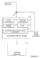
- Fig. 3 is a functional block diagram of a system for viewing virtual display outputs according to embodiments of the invention.
- Fig. 1 is a functional block diagram of a system 10 for generating a compensated video output according to embodiments of the invention.
- An image source such as a video, virtual-reality images, or other images is provided to a display model that includes modeling information specific for selected types of displays.
- a display model selector 70 may select, for instance, an LCD display model 30, CRT display model 40, DMD (Digital Micromirror Device) display model 50, or other display model 60. Also, the display model selector 70 may bypass the display model selection completely by choosing the bypass mode 20.
- Display models 30-60 include various data, such as color data, white balance, gamma information, etc., about a particular type of display. Display models may include translations from one particular color space to another, with particular parameters specific to the particular display model type.
- digital video streams and files commonly use YCbCr tristimulus representation as per ITU-R BT.601 for standard definition video and ITU-R BT.709 for high definition video, or in some cases RGB.
- direct XYZ representation is already directly supported as per the DCI (Digital Cinema Initiatives) "Digital Cinema System Specification,” commonly referred to as the "DCI Specification.”
- a standard such as according to 601, 709, SMPTE-C, EBU or whatever best represents the appropriate display to be simulated
- each display model technology has a unique initialization function for such things as creating look-up tables, setting filter parameters (for LCD), etc. It is within these functions that the following color model initialization takes place.
- Initialization of the color model includes the initialization of white point calibration weights ⁇ wr,wg,wb ⁇ along with any required look-up tables.
- Converting color data from YCbCr to XYZ may be performed directly using general computation circuitry or equivalent functions. For instance, first, a conversion of YCbCr to ER,EG,EB, according to standards, would use 9 multiplys and 6 adds. Applying a gamma factor to the result then uses 3 exponentials. Applying weights to create a white point may take a further 3 multiplys. Finally, a conversion of RGB light to XYZ (RGB Vector * matrix) takes another 9 multiplys and 5 adds, for a total of 18 8 multiplies, 12 adds, and 3 exponentials.
- LUT Look Up Table
- Embodiments of the invention may use any method for color conversion, of course, and the choice of which method to use is typically an implementation choice.
- a direct YCbCr to XYZ conversion may be performed by the use of a LUT, the size of which depending on bit depth. For example, for 8 bit video depth, the number of memory locations for the LUT would be on the order of 6.7 x 10 7 bits, which is a practical implementation given present day storage costs. 10 bit video depth and 12 bit video depth would require LUT sizes on the order of 4.3 x 10 9 bits, and 2.7 x 10 11 bits, which is currently not practical for typical implementations.
- the color conversion is made from YCbCr to RGB (light), because temporal processing for LCDs, as described below, occurs in RGB light space.
- the size of a LUT for LCD processing is the same as for CRTs and DMDs at the same bit depths.
- YCbCr is converted to ER,EG,EB according to the corresponding colorimetry standard (601, 709, etc.)
- the value of normalized (to unity) ER, EG, and EB values are converted to normalized (to unity) RGB light values using gamma, contrast and brightness controls, effectively reusing a luminance model already existing in quality analyzers by applying it to each primary color channel.
- the subsequent RGB to XYZ light conversion takes into account the actual luminance levels of each.
- White is represented as equal "electrical signal" amplitudes of R,G and B.
- white point calibration is usually performed.
- white point calibration weights R,G and/or B light output such that the amplitudes are altered in order to achieve the white point.
- limits here normalized to 1 of max and min R, G and B, find the relative ratios of RGB such that the given white point is achieved. Calculation of the weights ⁇ wr,wg,wb ⁇ may be performed as illustrated in Fig. 2 .
- RGB and White CIE 1931 xyY coordinates given either by:
- the XYZ output of the display model should be equal to XwTarget, YwTarget and ZwTarget respectively.
- Y values for R,G,B and W depend on the 1) choice of gamma, 2) maximum luminance value and 3) the light R,G,B to Y conversion.
- the first two parameters are already included in the already existing luminance only display models in quality analyzers.
- the third set of 3 weights for R,G and B respectively will generally be calculated from the coordinates of the primaries and white point along with the first two parameters.
- the RGB to Y conversion is also defined within many standards (i.e. ITU.B-709 HD) via the matrix to convert RGB to XYZ. Including explicit values from each standard, such as ITU.B-709 HD, SMPTE-C, EBU, NTSC, and SMPTE-240M would be redundant, since direct calculation gives the same results for Y, as described below.
- the most general display model of LCD technology includes temporal filtering to represent the "zero order hold" aspect of constant or high duty cycle backlighting, or reflected light during the time between frame transitions.
- a temporal filter is applied to the simulated light output for the luminance only model (applied to Y).
- this filter is instead applied to RGB (light primaries) outputs prior to conversion to XYZ.
- Advanced LCD configuration includes the use of modulated backlight.
- Modem LCD displays include backlight modulation to mitigate the motion blur problem associated with even theoretical 0 response time technology.
- the temporal filtering would be modified accordingly:
- parameters such as the duty cycle and phase of the backlight on-off and off-on transitions are received as display specifications.
- the temporal filter is updated accordingly, with the simulated results tracking the real results of greatly mitigated motion blur.
- the temporal filter may be eliminated since the integration in the human eye (accounted for in the human vision model) will sufficiently attenuate remaining high frequency information.
- a calculation of initialization of matrix M_RGBlight2XYZ is initialized during the display initialization as follows:
- an optional view model or virtual reality viewing environment 80 may add a factor to the output of the selected display model type to more accurately reflect the viewing environment of the display. For example, information about the ambient light, reflected light, or other simulated light may be added linearly to the XYZ representation of the display, using a CIE XYZ representation of the added light information. This view model information is used to modify the predicted picture/video quality rating.
- any virtual environment aspect may also be similarly included in the view model, also by using the CIE XYZ representation of such added information.
- Such information may include relatively basic information, for example, information about the display bezel of the display device, or may be as complex as a detailed virtual reality rendering.
- Fig. 3 is a functional block diagram of a system for viewing simulated or virtual display outputs according to embodiments of the invention, providing additional detail about the reverse display model 90 of Fig. 1 .
- a reverse display model 310 of Fig. 3 may be an example embodiment of the reverse display model 90 of Fig. 1 .
- the reverse display model 310 includes facilities for color conversion 312, white point calibration 314, gamma 316, temporal filtering 318, and a view model 320.
- the components of the reverse display model 310 of Fig. 3 are similar or identical to their counterpart components in the (forward) display models described above.
- the various factors included within components or sections of the reverse display model 310 may be pre-stored within the display model.
- the particular factors specific to the actual display 340 may be selected, for example as a menu choice on the system.
- the actual display 340 may identify itself to the system, and a look-up performed to select the appropriate factors for the reverse display model 310.
- the reverse display model 310 in contrast to the standard display models 30-60 of Figure 1 , operates in "reverse.”
- conversion to standard video representation (which can include XYZ representation) for the actual display 340 is performed.
- standard video representation which can include XYZ representation
- the inverse of XYZ to RGB light using the primaries of the actual display to be used
- inverse gamma function may be performed from respectively inverting the matrices and functions described above.
- a simulated light output is generated, for instance, from video, imaging, or virtual reality, it is optionally passed through a display model for a particular selected display type.
- the simulated output is then passed to a reverse display model for an actual display, the reverse display model including a compensator for adapting the simulated output to the actual display, so the image viewed on the actual display is as close as possible to the perceived image represented by the virtual or simulated light.
- the compensations may include display primary (color) compensation and equivalent gamma compensation, white point calibration, temporal characteristics, and viewing environment of the actual display.
- the viewing environment may include color and brightness of surroundings and ambient light, and may also include a generated virtual reality viewing environment that includes other images.
- the compensations change in real time as the simulated light output, actual display viewing environment, and virtual reality environment changes.
- the actual display 340 used for viewing has sufficient if not superior color gamut, maximum luminance, response time, contrast (black level), and other specifications to accurately render the input image.
- the viewing conditions will also allow for accurate perception of the rendered image.
- the ambient light will be sufficiently low as to not raise the effective black level or move the perceived white point (chromatic shift) beyond target accuracy.
- components of the invention may be implemented in hardware, software, or a combination of the two, and may comprise a general purpose microprocessor, a digital signal processor (DSP), an application specific integrated circuit (ASIC), a field-programmable gate array (FPGA), or the like.
- DSP digital signal processor
- ASIC application specific integrated circuit
- FPGA field-programmable gate array
Landscapes
- Engineering & Computer Science (AREA)
- Multimedia (AREA)
- Signal Processing (AREA)
- Health & Medical Sciences (AREA)
- Biomedical Technology (AREA)
- General Health & Medical Sciences (AREA)
- Processing Of Color Television Signals (AREA)
- Controls And Circuits For Display Device (AREA)
Abstract
Description
- This disclosure is directed toward to video systems, and, more particularly, to a system and method that accurately displays images on a target device.
- It is sometimes difficult to evaluate video on a device, or even a machine structured to evaluate video when a simulated output cannot be accurately viewed on an attached display. For instance, a video engineer may wish to see how a particular video would look to a viewer watching a consumer LCD (Liquid Crystal Display) television, a producer viewing a studio CRT (Cathode Ray Tube), an engineer in a broadcast center, or an engineer in a product development laboratory. Currently some quality analyzers, such as the picture quality analyzer PQA500 from Tektronix of Beaverton, Oregon incorporates display models, simulating light and the human vision system in order to quantify differences for these types of applications. However, there is no way for users of such quality analyzers to directly experience the perceptual stimuli that are simulated. Instead, the video is rendered on the display that is used in conjunction with the quality analyzer. Further, display manufacturers have an unmet need to be able to automatically evaluate virtual designs, before a product is built. However, without being able to directly see the differences among display design options, much useful information is hidden from the display engineers.
- Although mathematical solutions exist for converting video from one color space to another, such as YCbCr to RGB to CIE 1931 XYZ linear light representation, such solutions do not take into account various display variation from standard RGB. For instance, XYZ coordinates of the purest red, green, or blue represented by the digital video may not match the corresponding XYZ coordinates on the end display. Further, these relationships do not account for a mis-match in gamma values, i.e., a parameter used to represent the non-linear transfer function between the input signal and output light intensity, because the equivalent gamma of a display may not match the gamma in any corresponding standard.
- Even in cases where the primaries and gamma do match a standard, such as SMPTE-C for standard definition, or ITU 709 for high definition video, white point calibration is often intentionally set to a non-default value. For instance, a computer monitor typically set at 9500° default color temperature may instead have its white point set to 6500° to match a television default color temperature. This white point calibration allows a display with one set of primaries to come close to looking like a display with another set of primaries. However, such conversion is not included in the color conversion formulae mentioned above, and does so by shifting colors in a way that many colors in the gamut are lost.
- Other potential solutions require expensive and specialized equipment to physically measure output from a first display to create a conversion process from a first to a second display, which is expensive, complex, and too computationally intensive to provide a generalized solution. In addition, it requires an actual display to be measured, and not a modeled display. Further, no system, including the direct measuring systems, includes a way to compensate for response times of LCDs between the end of a video frame and the beginning of a next one. This leads to unacceptable and sometimes very perceptible display artifacts, such as motion blur.
- Embodiments of the invention address this and other limitations of the prior art.
- A system using reverse modeling of a target display type converts simulated light output into a signal that, when rendered on the target display, produces a perceptual response equivalent or nearly equivalent to that of the original simulated light. Further, methods are provided that can adapt to a given available display so that when rendered on the available display, the perceived image closely represents the perceived image of the simulated light or a virtual image.
- Particular embodiments of the invention are directed to methods for viewing a simulated light output generated for a selected display type on a second display. The method includes first generating the simulated light output based on qualities of the first display type. Next the simulated light output is compensated for viewing environment of the second display in real-time. After the compensation is complete, the simulated light output that has been compensated is output for the second display.
-
Fig. 1 is a functional block diagram of a system for generating a compensated video output according to embodiments of the invention. -
Fig. 2 is a series of equations for calculating weights for white balance calculation used in embodiments of the invention. -
Fig. 3 is a functional block diagram of a system for viewing virtual display outputs according to embodiments of the invention. -
Fig. 1 is a functional block diagram of asystem 10 for generating a compensated video output according to embodiments of the invention. An image source, such as a video, virtual-reality images, or other images is provided to a display model that includes modeling information specific for selected types of displays. Adisplay model selector 70 may select, for instance, anLCD display model 30, CRTdisplay model 40, DMD (Digital Micromirror Device)display model 50, orother display model 60. Also, thedisplay model selector 70 may bypass the display model selection completely by choosing thebypass mode 20. - Display models 30-60 include various data, such as color data, white balance, gamma information, etc., about a particular type of display. Display models may include translations from one particular color space to another, with particular parameters specific to the particular display model type. For video applications, digital video streams and files commonly use YCbCr tristimulus representation as per ITU-R BT.601 for standard definition video and ITU-R BT.709 for high definition video, or in some cases RGB. For digital cinema, direct XYZ representation is already directly supported as per the DCI (Digital Cinema Initiatives) "Digital Cinema System Specification," commonly referred to as the "DCI Specification."
- Display model color conversion
- Conversion of YCbCr to RGB (and to XYZ)
- For SD and HD video, translation of YCbCr to XYZ may be done as follows:
- 1) Initialization of the color model:
- a) White point cal: Using RGB and White CIE1931 xyY coordinates given either by:
- i) a standard such as according to 601, 709, SMPTE-C, EBU or whatever best represents the appropriate display to be simulated); or
- ii) Custom user defined xr,yr,Yr xg,yg,Yg, xb,yb,Yb, xw,yw,Yw.
- b) Calculate the required weights {wr,wg,wb} applied to R,G and B in order to achieve the given white point (xw,yw,Yw) for R=G=B.
- c) Calculate light conversion matrix for RGB to XYZ conversion, as described below
- d) LUT (Look Up Table) initialization:
- i) First, use respective standard translations of YCbCr to pre-gamma RGB {ER,EG,EB} using matrix defined by respective colorimetry standard (601, 709, etc.);
- ii) Convert {ER,EG,EB} to light {R,G,B} using contrast, gamma and brightness parameters;
- iii) Apply weights {wr,wg,wb} to {R,G,B};
- (For LCD, end LUT calc. here).
- iv) Convert weighted RGB light to XYZ using a matrix
- 2a) For CRT & DMD, convert YCbCr directly to XYZ using a LUT or direct calculation, depending on the implementation.
- 2b) For LCD, convert YCbCr to {wr*R,wg*G,wb*B} using a LUT or direct calculation, depending on the implementation, then use RGB to XYZ conversion matrix to finish conversion.
- For luminance only processing, i.e., without color, each display model technology has a unique initialization function for such things as creating look-up tables, setting filter parameters (for LCD), etc. It is within these functions that the following color model initialization takes place. Initialization of the color model includes the initialization of white point calibration weights {wr,wg,wb} along with any required look-up tables.
- Display model using LUTs for color conversion
- Converting color data from YCbCr to XYZ may be performed directly using general computation circuitry or equivalent functions. For instance, first, a conversion of YCbCr to ER,EG,EB, according to standards, would use 9 multiplys and 6 adds. Applying a gamma factor to the result then uses 3 exponentials. Applying weights to create a white point may take a further 3 multiplys. Finally, a conversion of RGB light to XYZ (RGB Vector * matrix) takes another 9 multiplys and 5 adds, for a total of 18 8 multiplies, 12 adds, and 3 exponentials.
- Using a Look Up Table (LUT), however, to perform equivalent color compensation, would only use 2 shifters, 2 adders, and 1 table access, and is therefore an attractive option to use fewer resources. Of course, the display model would need to include memory to store the LUT, but this is typically quite a reasonable tradeoff. Embodiments of the invention may use any method for color conversion, of course, and the choice of which method to use is typically an implementation choice.
- For CRT and DMD, a direct YCbCr to XYZ conversion may be performed by the use of a LUT, the size of which depending on bit depth. For example, for 8 bit video depth, the number of memory locations for the LUT would be on the order of 6.7 x 107 bits, which is a practical implementation given present day storage costs. 10 bit video depth and 12 bit video depth would require LUT sizes on the order of 4.3 x 109 bits, and 2.7 x 1011 bits, which is currently not practical for typical implementations.
- For LCD, the color conversion is made from YCbCr to RGB (light), because temporal processing for LCDs, as described below, occurs in RGB light space. The size of a LUT for LCD processing is the same as for CRTs and DMDs at the same bit depths.
- Display model using trilinear interpolation for color conversion
- It is possible to perform a trilinear interpolation for color conversion as well, but may not be a practical consideration given the fact that other conversion, such as direct computation, may be more efficient.
- Conversion of YCbCr to ER,EG,EB
- YCbCr is converted to ER,EG,EB according to the corresponding colorimetry standard (601, 709, etc.)
- Conversion of ER,EG,EB to RGB (light)
- The value of normalized (to unity) ER, EG, and EB values are converted to normalized (to unity) RGB light values using gamma, contrast and brightness controls, effectively reusing a luminance model already existing in quality analyzers by applying it to each primary color channel. The subsequent RGB to XYZ light conversion takes into account the actual luminance levels of each.
- Display model white point calibration
- White is represented as equal "electrical signal" amplitudes of R,G and B. However, when the white point selected (by a standard or a user selecting a non-standard color temperature or other color coordinates) does not coincide with is combination of the R,G and B light output from the display, white point calibration is usually performed. In effect, white point calibration weights R,G and/or B light output such that the amplitudes are altered in order to achieve the white point. These weights, {wr,wg,wb} are calculated during display model initialization.
- Using RGB and White CIE1931 xyY coordinates for R,G,B and W (xr,yr,Yr xg,yg,Yg, xb,yb,Yb, xw,yw,Yw ), the required weights {wr,wg,wb} may be calculated and applied to light outputs for R,G and B in order to achieve the given white point (xw,yw,Yw) for electrical signal R=G=B. Given the above and that limits (here normalized to 1) of max and min R, G and B, find the relative ratios of RGB such that the given white point is achieved. Calculation of the weights {wr,wg,wb} may be performed as illustrated in
Fig. 2 . - Next, white points can be calibrated by using RGB and White CIE 1931 xyY coordinates given either by:
- - Standards such as according to 601, 709, SMPTE-C, EBU or whatever best represents the appropriate display to be simulated) or
- - Custom user defined xr,yr,Yr xg,yg,Yg, xb,yb,Yb, xw,yw,Yw
- Verification of white point calibration may be performed by the use of colorless (achromatic) video such as all white video (RGB with all channels equal to max white (235) or YCbCr with Y=235, Cb=Cr=128, etc.). The XYZ output of the display model should be equal to XwTarget, YwTarget and ZwTarget respectively.
- Display model chromaticity coordinates of primary colors and whites
- Note that Y values for R,G,B and W (Yr,Yg,Yb,Yw) depend on the 1) choice of gamma, 2) maximum luminance value and 3) the light R,G,B to Y conversion. The first two parameters are already included in the already existing luminance only display models in quality analyzers. The third set of 3 weights for R,G and B respectively will generally be calculated from the coordinates of the primaries and white point along with the first two parameters. However, the RGB to Y conversion is also defined within many standards (i.e. ITU.B-709 HD) via the matrix to convert RGB to XYZ. Including explicit values from each standard, such as ITU.B-709 HD, SMPTE-C, EBU, NTSC, and SMPTE-240M would be redundant, since direct calculation gives the same results for Y, as described below.
- Display model temporal filtering for LCDs
- The most general display model of LCD technology includes temporal filtering to represent the "zero order hold" aspect of constant or high duty cycle backlighting, or reflected light during the time between frame transitions. In order to model this, a temporal filter is applied to the simulated light output for the luminance only model (applied to Y). For a full color model, this filter is instead applied to RGB (light primaries) outputs prior to conversion to XYZ.
- Advanced LCD configuration includes the use of modulated backlight. Modem LCD displays include backlight modulation to mitigate the motion blur problem associated with even theoretical 0 response time technology. The temporal filtering would be modified accordingly: In order to model steady backlight or reflected light, the temporal filter is the cascade of a zero-order hold filter (= 0 response time step function change in luminance at each frame transition) and simple low-pass filter representing the response time. In order to model backlight modulation, parameters such as the duty cycle and phase of the backlight on-off and off-on transitions are received as display specifications. The temporal filter is updated accordingly, with the simulated results tracking the real results of greatly mitigated motion blur. For low duty cycle (back or reflected) light, especially raster scanned methods that mimic CRT's, the temporal filter may be eliminated since the integration in the human eye (accounted for in the human vision model) will sufficiently attenuate remaining high frequency information.
- Matrix Conversion from RGB (light) to XYZ
- A calculation of initialization of matrix M_RGBlight2XYZ is initialized during the display initialization as follows:
-

Noting that the weighted sum of R=1, G=1, B=1 should result in Y=1: c :=0.. 2
- An example matrix calculation using SMPTE C and wtnorm[i] = 1 is given below, using 100 nits as the maximum luminance level. Note that the maximum luminance level does not matter for the normalized matrix.
-

-

- Compare this numerical example with the corresponding coefficients taken from SMPTE-C:
-


- View model
- Referring back to
Fig. 1 , an optional view model or virtualreality viewing environment 80 may add a factor to the output of the selected display model type to more accurately reflect the viewing environment of the display. For example, information about the ambient light, reflected light, or other simulated light may be added linearly to the XYZ representation of the display, using a CIE XYZ representation of the added light information. This view model information is used to modify the predicted picture/video quality rating. - Additionally, any virtual environment aspect may also be similarly included in the view model, also by using the CIE XYZ representation of such added information. Such information may include relatively basic information, for example, information about the display bezel of the display device, or may be as complex as a detailed virtual reality rendering.
-
Fig. 3 is a functional block diagram of a system for viewing simulated or virtual display outputs according to embodiments of the invention, providing additional detail about thereverse display model 90 ofFig. 1 . - A
reverse display model 310 ofFig. 3 may be an example embodiment of thereverse display model 90 ofFig. 1 . Thereverse display model 310 includes facilities forcolor conversion 312,white point calibration 314,gamma 316,temporal filtering 318, and aview model 320. The components of thereverse display model 310 ofFig. 3 are similar or identical to their counterpart components in the (forward) display models described above. The various factors included within components or sections of thereverse display model 310 may be pre-stored within the display model. In the case that theactual display 340 is known, the particular factors specific to theactual display 340 may be selected, for example as a menu choice on the system. In other embodiments theactual display 340 may identify itself to the system, and a look-up performed to select the appropriate factors for thereverse display model 310. - The
reverse display model 310, in contrast to the standard display models 30-60 ofFigure 1 , operates in "reverse." In other words, from the XYZ simulated light representation of an image to be evaluated, which was generated for a selected target display type, conversion to standard video representation (which can include XYZ representation) for theactual display 340 is performed. For target displays 340 that do not support XYZ, the inverse of XYZ to RGB light (using the primaries of the actual display to be used), inverse gamma function, and any further conversion (such as standard conversion to YCbCr) may be performed from respectively inverting the matrices and functions described above. - In operation, as a simulated light output is generated, for instance, from video, imaging, or virtual reality, it is optionally passed through a display model for a particular selected display type. The simulated output is then passed to a reverse display model for an actual display, the reverse display model including a compensator for adapting the simulated output to the actual display, so the image viewed on the actual display is as close as possible to the perceived image represented by the virtual or simulated light. The compensations may include display primary (color) compensation and equivalent gamma compensation, white point calibration, temporal characteristics, and viewing environment of the actual display. The viewing environment may include color and brightness of surroundings and ambient light, and may also include a generated virtual reality viewing environment that includes other images. The compensations change in real time as the simulated light output, actual display viewing environment, and virtual reality environment changes.
- In a preferred embodiment, the
actual display 340 used for viewing has sufficient if not superior color gamut, maximum luminance, response time, contrast (black level), and other specifications to accurately render the input image. Also, ideally, the viewing conditions will also allow for accurate perception of the rendered image. For example, the ambient light will be sufficiently low as to not raise the effective black level or move the perceived white point (chromatic shift) beyond target accuracy. - Although many of the embodiments described above include a user interface, it will be appreciated that in other embodiments, those parameters may alternatively be determined automatically by a test and measurement instrument
- In various embodiments, components of the invention may be implemented in hardware, software, or a combination of the two, and may comprise a general purpose microprocessor, a digital signal processor (DSP), an application specific integrated circuit (ASIC), a field-programmable gate array (FPGA), or the like.
- It will be appreciated from the forgoing discussion that the present invention represents a significant advance in the field of display modeling. Although specific embodiments of the invention have been illustrated and described for purposes if illustration, it will be understood that various modifications may be made without departing from the scope of the invention. Accordingly, the invention should not be limited except as by the appended claims.
Claims (13)
- A method for viewing a simulated light output generated for a first display type on a second display, the method comprising:generating the simulated light output based on qualities of the first display type;compensating the simulated light output for a viewing environment of the second display; andoutputting the simulated light output that has been compensated for color differences and for viewing environment to the second display.
- The method of claim 1 in which compensating the simulated light output for a viewing environment of the second display comprises compensating the simulated light output for a viewing environment of the second display in real time.
- The method of claim 1 or 2 in which the viewing environment of the second display comprises a virtual reality created viewing environment.
- The method of any of claims 1 to 3, further comprising:compensating the simulated light output for color differences between the first and the second display.
- The method of any of claims 1 to 4 in which the color differences are compensated using matrix manipulation.
- The method of any of claims 1 to 5, further comprising:temporally compensating the simulated light output before providing it to the second display.
- A device for generating simulated light output, comprising:a generator for generating a simulated light output based on qualities of a first display;a reverse display model structured to compensate the simulated light output for differences between the first display and a second display; andan output for sending the compensated simulated light output for viewing on the second display.
- The device of claim 7, in which the reverse display model comprises a color conversion facility.
- The device of claim 7, in which the reverse display model comprises a white point calibration facility.
- The device of claim 7, in which the reverse display model comprises a temporal filter.
- The device of claim 7, in which the reverse display model comprises a view model of the second display.
- The device of claim 11, in which the view model accepts a viewing environment that is at least partially generated in a virtual reality generator.
- The device of claim 12, in which the virtual reality generator is a component of the device for generating simulated light output.
Applications Claiming Priority (1)
| Application Number | Priority Date | Filing Date | Title |
|---|---|---|---|
| US13/340,517 US9013502B2 (en) | 2011-12-29 | 2011-12-29 | Method of viewing virtual display outputs |
Publications (2)
| Publication Number | Publication Date |
|---|---|
| EP2611183A2 true EP2611183A2 (en) | 2013-07-03 |
| EP2611183A3 EP2611183A3 (en) | 2014-02-19 |
Family
ID=47720241
Family Applications (1)
| Application Number | Title | Priority Date | Filing Date |
|---|---|---|---|
| EP20120198744 Ceased EP2611183A3 (en) | 2011-12-29 | 2012-12-20 | Method for viewing virtual display outputs |
Country Status (4)
| Country | Link |
|---|---|
| US (1) | US9013502B2 (en) |
| EP (1) | EP2611183A3 (en) |
| JP (1) | JP6351202B2 (en) |
| CN (1) | CN103383830B (en) |
Families Citing this family (8)
| Publication number | Priority date | Publication date | Assignee | Title |
|---|---|---|---|---|
| WO2014017388A1 (en) * | 2012-07-25 | 2014-01-30 | シャープ株式会社 | Display device and display method |
| CN104240674B (en) * | 2013-06-14 | 2016-10-05 | 联想(北京)有限公司 | A kind of method regulating display unit and a kind of electronic equipment |
| WO2014069349A1 (en) * | 2012-11-02 | 2014-05-08 | シャープ株式会社 | Display device and display method |
| JP2015108796A (en) * | 2013-10-22 | 2015-06-11 | キヤノン株式会社 | Image display system, image display system control method, image display apparatus, and image display apparatus control method |
| JP2015121954A (en) * | 2013-12-24 | 2015-07-02 | 株式会社デンソー | Luminance value calculation device and traffic lane detection system |
| KR102061233B1 (en) | 2014-01-20 | 2020-01-02 | 삼성디스플레이 주식회사 | Display device and integrated circuit chip |
| US10345768B2 (en) * | 2014-09-29 | 2019-07-09 | Microsoft Technology Licensing, Llc | Environmental control via wearable computing system |
| US10121419B2 (en) * | 2015-11-13 | 2018-11-06 | Google Llc | Head mounted display device with rapid gamma correction between display panels |
Citations (3)
| Publication number | Priority date | Publication date | Assignee | Title |
|---|---|---|---|---|
| EP0700218A2 (en) * | 1994-08-04 | 1996-03-06 | Lg Electronics Inc. | Image compensation system for video appliances and methods thereof |
| EP1189457A2 (en) * | 2000-09-13 | 2002-03-20 | Seiko Epson Corporation | Correction curve generating method, image processing method, image display unit and storage medium |
| EP1914980A1 (en) * | 2006-10-17 | 2008-04-23 | Samsung Electronics Co., Ltd. | Apparatus and method for improving visibility of image |
Family Cites Families (13)
| Publication number | Priority date | Publication date | Assignee | Title |
|---|---|---|---|---|
| JPH1132228A (en) * | 1997-02-21 | 1999-02-02 | Sony Corp | Transmission device, transmission method, reception device, reception method, image processing system, image processing method, image data processing device, image data processing method, and providing medium |
| JP3658141B2 (en) * | 1997-05-21 | 2005-06-08 | キヤノン株式会社 | Image processing apparatus and image processing method |
| US6847374B2 (en) * | 2000-07-31 | 2005-01-25 | Seiko Epson Corporation | Environment-compliant image display system and program |
| DE60110399T2 (en) * | 2000-08-28 | 2006-01-19 | Seiko Epson Corp. | ANIMAL ADJUSTING DISPLAY SYSTEM, IMAGE PROCESSING METHOD AND PICTURE MEMORY |
| JP3876650B2 (en) * | 2001-06-06 | 2007-02-07 | 日本電気株式会社 | Color correction parameter calculation device, image color correction device, color correction parameter calculation method used therefor, and program thereof |
| US7487118B2 (en) | 2005-05-06 | 2009-02-03 | Crutchfield Corporation | System and method of image display simulation |
| US7593017B2 (en) | 2006-08-15 | 2009-09-22 | 3M Innovative Properties Company | Display simulator |
| JP2008085980A (en) * | 2006-08-31 | 2008-04-10 | Sony Corp | Color conversion apparatus, emulation method, three-dimensional lookup table generation method, and image processing apparatus |
| TWI394121B (en) * | 2006-12-18 | 2013-04-21 | Sony Corp | An image processing apparatus, an image processing method, and a recording medium |
| JP2008178075A (en) | 2006-12-18 | 2008-07-31 | Sony Corp | Display control apparatus, display control method, and program |
| WO2011028626A2 (en) * | 2009-09-01 | 2011-03-10 | Entertainment Experience Llc | Method for producing a color image and imaging device employing same |
| US20110273451A1 (en) * | 2010-05-10 | 2011-11-10 | Salemann Leo J | Computer simulation of visual images using 2d spherical images extracted from 3d data |
| US9153200B2 (en) * | 2011-05-13 | 2015-10-06 | Samsung Display Co., Ltd. | Method for selecting backlight color values |
-
2011
- 2011-12-29 US US13/340,517 patent/US9013502B2/en active Active
-
2012
- 2012-12-20 EP EP20120198744 patent/EP2611183A3/en not_active Ceased
- 2012-12-28 CN CN201210597131.3A patent/CN103383830B/en not_active Expired - Fee Related
- 2012-12-28 JP JP2012288303A patent/JP6351202B2/en not_active Expired - Fee Related
Patent Citations (3)
| Publication number | Priority date | Publication date | Assignee | Title |
|---|---|---|---|---|
| EP0700218A2 (en) * | 1994-08-04 | 1996-03-06 | Lg Electronics Inc. | Image compensation system for video appliances and methods thereof |
| EP1189457A2 (en) * | 2000-09-13 | 2002-03-20 | Seiko Epson Corporation | Correction curve generating method, image processing method, image display unit and storage medium |
| EP1914980A1 (en) * | 2006-10-17 | 2008-04-23 | Samsung Electronics Co., Ltd. | Apparatus and method for improving visibility of image |
Also Published As
| Publication number | Publication date |
|---|---|
| US9013502B2 (en) | 2015-04-21 |
| JP2013141239A (en) | 2013-07-18 |
| EP2611183A3 (en) | 2014-02-19 |
| JP6351202B2 (en) | 2018-07-04 |
| US20130169826A1 (en) | 2013-07-04 |
| CN103383830A (en) | 2013-11-06 |
| CN103383830B (en) | 2017-04-12 |
Similar Documents
| Publication | Publication Date | Title |
|---|---|---|
| US9013502B2 (en) | Method of viewing virtual display outputs | |
| JP3719411B2 (en) | Image display system, projector, program, information storage medium, and image processing method | |
| KR100710302B1 (en) | Apparatus and method for color correction of a display device | |
| CN102063888B (en) | Method and device for managing colors | |
| US8098932B2 (en) | Color correction method and apparatus of display apparatus | |
| US20110305391A1 (en) | Image Processing and Displaying Methods for Devices that Implement Color Appearance Models | |
| US8411936B2 (en) | Apparatus and method for color reproduction | |
| CN101171848A (en) | Color conversion brightness correction method and device | |
| EP2200268B1 (en) | Method of calibration of a target color reproduction device | |
| US20110148907A1 (en) | Method and system for image display with uniformity compensation | |
| CN101188096A (en) | A LCD color domain mapping algorithm and color management system | |
| US9111477B2 (en) | Language-based color calibration of displays | |
| CA2661650C (en) | Video monitoring device providing parametric signal curve display features and related methods | |
| US20080095430A1 (en) | Maintenance of Color Maximum Values in a Color Saturation Controlled Color Image | |
| US20060071937A1 (en) | Color characterization of projectors | |
| JP2005196156A (en) | Color image display device, color conversion device, color simulation device, and methods thereof | |
| Nezamabadi et al. | Effect of image size on the color appearance of image reproductions using colorimetrically calibrated LCD and DLP displays | |
| Kim | Optically adjustable display color gamut in time-sequential displays using LED/Laser light sources | |
| Cho et al. | Inverse characterization method of alternate gain-offset-gamma model for accurate color reproduction in display device | |
| KR100827128B1 (en) | Imaging Method of Portable Imaging Device | |
| JP2006033881A (en) | Image display apparatus, image processing method, and program | |
| US12056913B2 (en) | System for luminance qualified chromaticity | |
| Park et al. | Color Reproduction Using “Black-Point Adaptation” | |
| Koch et al. | Spatial Color Confidence for Physically based Rendering Settings on LC Displays. | |
| Becker | 50‐3: Electro‐Optical Transfer Characteristic, the Undervalued Display Feature |
Legal Events
| Date | Code | Title | Description |
|---|---|---|---|
| PUAI | Public reference made under article 153(3) epc to a published international application that has entered the european phase |
Free format text: ORIGINAL CODE: 0009012 |
|
| AK | Designated contracting states |
Kind code of ref document: A2 Designated state(s): AL AT BE BG CH CY CZ DE DK EE ES FI FR GB GR HR HU IE IS IT LI LT LU LV MC MK MT NL NO PL PT RO RS SE SI SK SM TR |
|
| AX | Request for extension of the european patent |
Extension state: BA ME |
|
| PUAL | Search report despatched |
Free format text: ORIGINAL CODE: 0009013 |
|
| AK | Designated contracting states |
Kind code of ref document: A3 Designated state(s): AL AT BE BG CH CY CZ DE DK EE ES FI FR GB GR HR HU IE IS IT LI LT LU LV MC MK MT NL NO PL PT RO RS SE SI SK SM TR |
|
| AX | Request for extension of the european patent |
Extension state: BA ME |
|
| RIC1 | Information provided on ipc code assigned before grant |
Ipc: H04N 9/68 20060101ALI20140114BHEP Ipc: H04N 13/04 20060101AFI20140114BHEP Ipc: H04N 17/04 20060101ALI20140114BHEP Ipc: H04N 9/74 20060101ALI20140114BHEP Ipc: H04N 1/60 20060101ALI20140114BHEP Ipc: H04N 9/67 20060101ALI20140114BHEP |
|
| 17P | Request for examination filed |
Effective date: 20140818 |
|
| RAP1 | Party data changed (applicant data changed or rights of an application transferred) |
Owner name: TEKTRONIX, INC. |
|
| RBV | Designated contracting states (corrected) |
Designated state(s): AL AT BE BG CH CY CZ DE DK EE ES FI FR GB GR HR HU IE IS IT LI LT LU LV MC MK MT NL NO PL PT RO RS SE SI SK SM TR |
|
| 17Q | First examination report despatched |
Effective date: 20150702 |
|
| STAA | Information on the status of an ep patent application or granted ep patent |
Free format text: STATUS: THE APPLICATION HAS BEEN REFUSED |
|
| 18R | Application refused |
Effective date: 20170328 |