EP2611129A1 - Image forming apparatus - Google Patents
Image forming apparatus Download PDFInfo
- Publication number
- EP2611129A1 EP2611129A1 EP12008200.3A EP12008200A EP2611129A1 EP 2611129 A1 EP2611129 A1 EP 2611129A1 EP 12008200 A EP12008200 A EP 12008200A EP 2611129 A1 EP2611129 A1 EP 2611129A1
- Authority
- EP
- European Patent Office
- Prior art keywords
- processing unit
- kernel
- image forming
- forming apparatus
- file system
- Prior art date
- Legal status (The legal status is an assumption and is not a legal conclusion. Google has not performed a legal analysis and makes no representation as to the accuracy of the status listed.)
- Ceased
Links
Images




Classifications
-
- G—PHYSICS
- G06—COMPUTING OR CALCULATING; COUNTING
- G06F—ELECTRIC DIGITAL DATA PROCESSING
- G06F3/00—Input arrangements for transferring data to be processed into a form capable of being handled by the computer; Output arrangements for transferring data from processing unit to output unit, e.g. interface arrangements
- G06F3/06—Digital input from, or digital output to, record carriers, e.g. RAID, emulated record carriers or networked record carriers
- G06F3/0601—Interfaces specially adapted for storage systems
- G06F3/0602—Interfaces specially adapted for storage systems specifically adapted to achieve a particular effect
- G06F3/0626—Reducing size or complexity of storage systems
-
- H—ELECTRICITY
- H04—ELECTRIC COMMUNICATION TECHNIQUE
- H04N—PICTORIAL COMMUNICATION, e.g. TELEVISION
- H04N1/00—Scanning, transmission or reproduction of documents or the like, e.g. facsimile transmission; Details thereof
- H04N1/00912—Arrangements for controlling a still picture apparatus or components thereof not otherwise provided for
- H04N1/00928—Initialisation or control of normal start-up or shut-down, i.e. non failure or error related
-
- H—ELECTRICITY
- H04—ELECTRIC COMMUNICATION TECHNIQUE
- H04N—PICTORIAL COMMUNICATION, e.g. TELEVISION
- H04N1/00—Scanning, transmission or reproduction of documents or the like, e.g. facsimile transmission; Details thereof
- H04N1/00912—Arrangements for controlling a still picture apparatus or components thereof not otherwise provided for
- H04N1/00938—Software related arrangements, e.g. loading applications
- H04N1/00941—Interaction of different applications
Definitions
- the present invention relates to image forming apparatuses.
- An image forming apparatus includes a main system and a panel system which controls an operation panel.
- the main system and the panel system perform different processes, respectively, and are connected to each other by communication interfaces and so forth.
- FIG. 8 shows a flowchart which explains a starting process of an image forming apparatus.
- Root file system for Processor #1 includes data and/or a program to be used by Processor #1
- the root file system for Processor #2 includes data and/or a program to be used by Processor #2.
- Steps S101 and S111 respective kernels are loaded and started (Steps S101 and S111).
- the kernels of Processors #1 and #2 mount root file systems, respectively (Steps S102 and S112).
- An image forming apparatus includes a first processing unit; a second processing unit configured to perform a process different from a process performed by the first processing unit; and a non volatile memory device in which a shared root file system has been stored, the shared root file system mounted by a kernel for the first processing unit and a kernel for the second processing unit.
- FIG. 1 shows a block diagram which indicates a configuration of an image forming apparatus according to Embodiment 1 of the present disclose.
- the present image forming apparatus includes a processor 1, a flash memory 2, a DRAM (Dynamic Random Access Memory) 3, a controller 4, an image processing device 5, a printing device 6, and an operation panel 7.
- the processor 1 is a multiple core processor, and includes plural cores 11a and 11b, a local bus controller 12, a DRAM controller 13, and a PCIe controller 14.
- the plural cores 11a and 11b are respective processing units which have the same circuit configuration, and execute programs in the flash memory 2 and programs loaded to the DRAM 3.
- the core 11a performs a boot loader to start a kernel of the core 11a and a kernel of the core 11b.
- a kernel of the core 11a For instance, a same version of Linux (trademark) is used as these kernels.
- the core 11b performs a job management process, and the core 11a performs a predetermined process other than the job management process.
- the core 11a is used for a panel system to control the operation panel 7, and the core 11b is used for a main system to perform job management and so forth.
- the local bus controller 12 performs data communication with the flash memory 2 and so forth connected to a local bus.
- the DRAM controller 13 performs data read and data write of the DRAM 3.
- the PCIe controller 14 performs data communication with the controller 4 using a PCIe (Peripheral Component Interconnect Express) interface.
- PCIe Peripheral Component Interconnect Express
- the system bus 15 is a data communication path which mutually connects the cores 11a and 11b and the controllers 12 to 14.
- the flash memory 2 is a non volatile memory device in which data and/or a program to be used by the plural cores 11a and 11b have been stored.
- the flash memory 2 is a NAND type flash memory.
- Figure 2 shows a diagram which indicates an example of memory areas of the flash memory 2 shown in Figure 1 .
- a program of a kernel (i.e. an operating system) for the core 11a and a program of a kernel (i.e. an operating system) for the core 11b have been stored.
- This root file system includes a binary program, a standard library, a script, and so forth. This root file system does not include any data and/or any programs to be rewritten by the cores 11a and 11b. In other words, this root file system includes only read-only data and/or a read-only program. Therefore, this root file system is a read-only file system such as cramfs or squashfs. Consequently, a write access to the root file system is prohibited, and a content of the root file system is protected.
- the flash memory 2 includes (a) a panel program area in which data and/or a program to be rewritten by the core 11a have been stored and (b) a main program area in which data and/or a program to be rewritten by the core 11b have been stored.
- the panel program area is mounted by the kernel of the core 11a
- the main program area is mounted by the kernel of the core 11b.
- Figure 3 shows a flowchart that indicates processes performed with a part of a program which is included in the root file system shown in Figure 2 and is to perform different processes from each other in a panel system and a main system.
- Such program is described to acquire an ID of a processing unit that is executing this program, and to perform a process corresponding to the acquired ID. Therefore, different processes can be performed in the respective systems.
- Embodiment 1 when the core ID of the core 11a is zero, and the core ID of the core 11b is 1, the core ID of a processing unit which is executing this program is acquired (Step S1), and it is determined whether the acquired core ID is zero or not (Step S2); if the acquired core ID is zero then a process for the panel system is performed (Step S3), and if the acquired core ID is 1 then a process for the main system is performed (Step S4).
- the DRAM 3 is a volatile memory to which data and/or a program are loaded to be used by the cores 11a and 11b.
- the DRAM 3 can perform data read and data write faster than those of the flash memory 2.
- the controller 4 is a circuit which controls peripheral devices of the processor 1 such as the image processing device 5 and the operation panel 7.
- the controller 4 includes a PCIe interface 21, a video controller 22, and a panel controller 23.
- the PCIe interface 21 performs data communication with the PCIe controller 14 of the processor 1.
- the video controller 22 performs printing by controlling the image processing device 5 and the printing device 6.
- the panel controller 23 controls the operation panel 7 to display information based on data supplied from the processor 1 and to supply information of a user operation to the operation panel 7. Therefore, in the panel system, the core 11a controls the operation panel 7 using the panel controller 23; and in the main system, the core 11b controls the image processing device 5 and the printing device 6 using the video controller 22.
- the image processing device 5 generates print image data to be supplied to the printing device 6 from image data generated by an unshown image scanning device, image data supplied from an unshown host device, and so forth.
- the printing device 6 prints an image based on the print image data generated by the image processing device 5, for example, in a manner of an electrophotography.
- the operation panel 7 is disposed a surface of a housing of this image forming apparatus, and includes a display device which displays information to a user and an input device which detects a user operation.
- the display device is a liquid crystal display, an indicator and so forth
- the input device is a touch panel, a button switch and so forth.
- Figure 4 shows a flowchart that explains a behavior of the image forming apparatus in a starting process in Embodiment 1.
- the core 11a starts an unshown boot loader stored in a predetermined memory area, for example, in the flash memory 2 (Step S11).
- the core 11a starts the kernel of the core 11a and the kernel of the core 11b using the boot loader (Steps S12 and S22).
- the cores 11a and 11b operate in accordance with the respective kernels.
- the core 11a mounts the root file system in accordance with the kernel (Step S13). Afterward, the core 11a mounts a panel program area to a predetermined lower directory such as /usr/local in accordance with the kernel (Step S14).
- the core 11b mounts the root file system in accordance with the kernel (Step S23). Afterward, the core 11b mounts a main program area to a predetermined lower directory such as /usr/local in accordance with the kernel (Step S24).
- the root file system in the flash memory 2 is accessed (read only) by both the cores 11a and 11b; the panel program area in the flash memory 2 is accessed (read and write) by only the core 11a among the cores 11a and 11b; and the main program area in the flash memory 2 is accessed (read and write) by only the core 11b among the cores 11a and 11b.
- the image forming apparatus includes (a) the processor 1 including the plural cores 11a and 11b, and (b) the flash memory 2 in which the shared file system to be mounted by both the kernel of the core 11a and the kernel of the core 11b has been stored.
- the image forming apparatus in Embodiment 2 of this disclosure includes a hardware configuration similar to that of the image forming apparatus in Embodiment 1.
- the core 11a loads the root file system to the DRAM 3, and mounts the root file system loaded to the DRAM 3; and the core 11b does not load the root file system to the DRAM 3, and mounts the root file system loaded by the core 11a to the DRAM 3.
- Figure 5 shows a diagram which indicates an example of memory areas allocated in the DRAM 3 in Embodiment 2.
- the root file system is loaded to an outside area of areas managed by the kernel of the core 11a and the kernel of the core 11b in the DRAM 3; and the kernels of the cores 11a and 11b manage the memory area where the root file system was loaded as a memory block device.
- This memory block device is, for example, an MTD (Memory Technology Device) device.
- the core 11a loads the root file system to an outside area of areas managed by the kernels of the cores 11a and 11b in the DRAM 3 using a boot loader, and then starts the kernel of the core 11a and the kernel of the core 11b.
- Figure 6 shows a flowchart that explains a behavior of the image forming apparatus in a starting process in Embodiment 2.
- the core 11a starts an unshown boot loader stored in a predetermined memory area, for example, in the flash memory 2 (Step S31). For instance, u-boot is used as this boot loader.
- the core 11a loads the root file system from the flash memory 2 to a predetermined physical address area in the DRAM 3 in accordance with the boot loader (Step S32).
- the core 11a starts the kernel of the core 11a and the kernel of the core 11b in accordance with the boot loader (Steps S33 and S43).
- the cores 11a and 11b operates in accordance with the respective kernels.
- the core 11a performs mapping the physical address area where the root file system was loaded to a logical address area, for example, using io_remap function in accordance with the kernel (Step S34), and generates and registers a memory block device (here, an MTD device) of this area (Step S35).
- the core 11a mounts the memory block device (i.e. the root file system) in accordance with the kernel (Step S36).
- the core 11a mounts the panel program area to a predetermined lower directory such as /usr/local in accordance with the kernel (Step S37).
- the core 11b performs mapping the physical address area where the root file system was loaded to a logical address area, for example, using io_remap function in accordance with the kernel (Step S44), and generates and registers a memory block device (here, an MTD device) of this area (Step S45).
- the core 11b mounts the memory block device (i.e. the root file system) in accordance with the kernel (Step S46).
- the core 11b mounts the main program area to a predetermined lower directory such as /usr/local in accordance with the kernel (Step S47).
- Information on the position of the physical address area where the root file system was loaded (e.g. the top address and the size) is provided to the kernels of the cores 11a and 11b from the boot loader when the boot loader starts the kernels. For instance, such information is provided as a command line parameter of u-boot.
- the root file system loaded in the DRAM 3 is accessed by both the cores 11a and 11b; the panel program area in the flash memory 2 is accessed by only the core 11a among the cores 11a and 11b; and the main program area in the flash memory 2 is accessed by only the core 11b among the cores 11a and 11b.
- Embodiment 2 Other parts in the configuration of the image forming apparatus in Embodiment 2 is identical to those in Embodiment 1, and therefore, not explained here.
- the core 11a loads the root file system to the DRAM 3, and mounts the root file system loaded in the DRAM 3.
- the core 11b mounts the root file system loaded by the core 11a in the DRAM 3.
- the size of a memory area required to the flash memory 2 is small. Further, since the root file system loaded in the DRAM 3 is used, data read and data write to the root file system in the DRAM 3 can be performed faster than those in the flash memory 2. Furthermore, in Embodiment 2, since this root file system includes only read-only data and/or a read-only program, the root file system is never changed. Therefore, after finishing using the root file system loaded in the DRAM 3, it is not necessary to write the root file system from the DRAM 3 back to the flash memory 2.
- the plural processing units are formed by the plural cores 11a and 11b included in the processor 1.
- the plural processing units may be formed by plural processors connected via a bus or the like.
- the core 11a is used for the panel system.
- the image forming apparatus may includes a network interface, and the core 11a may perform a communication process using this network interface.
- the memory block device of the root file system may be enabled to be in an address area after the area managed by the kernel of the core 11a and/or the area managed by the kernel of the core 11b.
- the kernel managing area and the area of the memory block device must not be overlapped to each other.
- io_remap function can not map a lower address than the top address of the kernel managing area (it results in an error to protect the kernel managing area), and therefore, in this case, io_remap function is modified to enable the modified io_remap function to map a lower address than the top address of the kernel managing area.
- Figure 7 shows a diagram which indicates another example of memory areas allocated in the DRAM 3 in Embodiment 2. As shown in Figure 7 , for example, the memory block device can be allocated in a lower address than the kernel managing area of the core 11b.
- the kernel of the core 11a may generate a RAM disk in the kernel managing area of the core 11a, load the panel program to the RAM disk, and mount the RAM disk instead of the panel program area included in the flash memory 2.
- the kernel of the core 11b may generate a RAM disk in the kernel managing area of the core 11a, load the main program to the RAM disk, and mount the RAM disk instead of the main program area included in the flash memory 2.
Landscapes
- Engineering & Computer Science (AREA)
- Multimedia (AREA)
- Signal Processing (AREA)
- Theoretical Computer Science (AREA)
- Human Computer Interaction (AREA)
- Physics & Mathematics (AREA)
- General Engineering & Computer Science (AREA)
- General Physics & Mathematics (AREA)
- Stored Programmes (AREA)
- Information Retrieval, Db Structures And Fs Structures Therefor (AREA)
- Facsimiles In General (AREA)
Abstract
Description
-
- The present invention relates to image forming apparatuses.
- An image forming apparatus includes a main system and a panel system which controls an operation panel. The main system and the panel system perform different processes, respectively, and are connected to each other by communication interfaces and so forth.
- In systems independent of each other like those of the aforementioned image forming apparatus, in general, the systems start respective kernels of operating systems, and mount respective file systems.
Figure 8 shows a flowchart which explains a starting process of an image forming apparatus. - As shown in
Figure 8 , forProcessors # 1 and #2 of two systems, respective kernels and root file systems have been stored in a flash memory. The root file system forProcessor # 1 includes data and/or a program to be used byProcessor # 1, and the root file system forProcessor # 2 includes data and/or a program to be used byProcessor # 2. - In the starting process of the image forming apparatus, for
Processors # 1 and #2, respective kernels are loaded and started (Steps S101 and S111). The kernels ofProcessors # 1 and #2 mount root file systems, respectively (Steps S102 and S112). - In the case that plural systems are used as mentioned above, for the systems, it is required that respective kernels and respective root file systems has been stored in a flash memory, and therefore, a large memory area is required to the flash memory.
- An image forming apparatus according to an aspect of the present disclosure includes a first processing unit; a second processing unit configured to perform a process different from a process performed by the first processing unit; and a non volatile memory device in which a shared root file system has been stored, the shared root file system mounted by a kernel for the first processing unit and a kernel for the second processing unit.
- Therefore, since one root file system is shared, the size of a memory area required to the non volatile memory device is small.
- These and other objects, features and advantages of the present invention will become more apparent upon reading of the following detailed description along with the accompanied drawings.
-
-
Figure 1 shows a block diagram which indicates a configuration of an image forming apparatus according toEmbodiment 1 of the present disclose; -
Figure 2 shows a diagram which indicates an example of memory areas of the flash memory shown inFigure 1 ; -
Figure 3 shows a flowchart that indicates processes performed with a part of a program which is included in a root file system shown inFigure 2 and is to perform different processes from each other in a panel system and a main system; -
Figure 4 shows a flowchart that explains a behavior of the image forming apparatus in a starting process inEmbodiment 1; -
Figure 5 shows a diagram which indicates an example of memory areas allocated in a DRAM inEmbodiment 2; -
Figure 6 shows a flowchart that explains a behavior of the image forming apparatus in a starting process inEmbodiment 2; -
Figure 7 shows a diagram which indicates another example of memory areas allocated in a DRAM inEmbodiment 2; and -
Figure 8 shows a flowchart that explains a behavior of an image forming apparatus in a starting process. - Hereinafter, embodiments according to aspects of the present disclosure will be explained with reference to drawings.
-
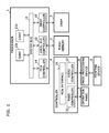
Figure 1 shows a block diagram which indicates a configuration of an image forming apparatus according toEmbodiment 1 of the present disclose. The present image forming apparatus includes aprocessor 1, aflash memory 2, a DRAM (Dynamic Random Access Memory) 3, acontroller 4, animage processing device 5, aprinting device 6, and anoperation panel 7. - The
processor 1 is a multiple core processor, and includesplural cores local bus controller 12, a DRAM controller 13, and aPCIe controller 14. - The
plural cores flash memory 2 and programs loaded to theDRAM 3. - Further, in
Embodiment 1, thecore 11a performs a boot loader to start a kernel of thecore 11a and a kernel of thecore 11b. For instance, a same version of Linux (trademark) is used as these kernels. - The
core 11b performs a job management process, and thecore 11a performs a predetermined process other than the job management process. InEmbodiment 1, thecore 11a is used for a panel system to control theoperation panel 7, and thecore 11b is used for a main system to perform job management and so forth. - The
local bus controller 12 performs data communication with theflash memory 2 and so forth connected to a local bus. - The DRAM controller 13 performs data read and data write of the
DRAM 3. - The
PCIe controller 14 performs data communication with thecontroller 4 using a PCIe (Peripheral Component Interconnect Express) interface. - The
system bus 15 is a data communication path which mutually connects thecores controllers 12 to 14. - Further, the
flash memory 2 is a non volatile memory device in which data and/or a program to be used by theplural cores flash memory 2 is a NAND type flash memory. -
Figure 2 shows a diagram which indicates an example of memory areas of theflash memory 2 shown inFigure 1 . - In the
flash memory 2, a program of a kernel (i.e. an operating system) for thecore 11a and a program of a kernel (i.e. an operating system) for thecore 11b have been stored. - Further, in the
flash memory 2, a shared root file system to be mounted both by the kernel of thecore 11a and by the kernel of thecore 11b has been stored. - This root file system includes a binary program, a standard library, a script, and so forth. This root file system does not include any data and/or any programs to be rewritten by the
cores - Further, the
flash memory 2 includes (a) a panel program area in which data and/or a program to be rewritten by thecore 11a have been stored and (b) a main program area in which data and/or a program to be rewritten by thecore 11b have been stored. The panel program area is mounted by the kernel of thecore 11a, and the main program area is mounted by the kernel of thecore 11b. -
Figure 3 shows a flowchart that indicates processes performed with a part of a program which is included in the root file system shown inFigure 2 and is to perform different processes from each other in a panel system and a main system. Such program is described to acquire an ID of a processing unit that is executing this program, and to perform a process corresponding to the acquired ID. Therefore, different processes can be performed in the respective systems. - In
Embodiment 1, when the core ID of thecore 11a is zero, and the core ID of thecore 11b is 1, the core ID of a processing unit which is executing this program is acquired (Step S1), and it is determined whether the acquired core ID is zero or not (Step S2); if the acquired core ID is zero then a process for the panel system is performed (Step S3), and if the acquired core ID is 1 then a process for the main system is performed (Step S4). - Further, the
DRAM 3 is a volatile memory to which data and/or a program are loaded to be used by thecores DRAM 3 can perform data read and data write faster than those of theflash memory 2. - The
controller 4 is a circuit which controls peripheral devices of theprocessor 1 such as theimage processing device 5 and theoperation panel 7. Thecontroller 4 includes aPCIe interface 21, avideo controller 22, and apanel controller 23. ThePCIe interface 21 performs data communication with thePCIe controller 14 of theprocessor 1. Thevideo controller 22 performs printing by controlling theimage processing device 5 and theprinting device 6. Thepanel controller 23 controls theoperation panel 7 to display information based on data supplied from theprocessor 1 and to supply information of a user operation to theoperation panel 7. Therefore, in the panel system, thecore 11a controls theoperation panel 7 using thepanel controller 23; and in the main system, the core 11b controls theimage processing device 5 and theprinting device 6 using thevideo controller 22. - The
image processing device 5 generates print image data to be supplied to theprinting device 6 from image data generated by an unshown image scanning device, image data supplied from an unshown host device, and so forth. Theprinting device 6 prints an image based on the print image data generated by theimage processing device 5, for example, in a manner of an electrophotography. - The
operation panel 7 is disposed a surface of a housing of this image forming apparatus, and includes a display device which displays information to a user and an input device which detects a user operation. For example, the display device is a liquid crystal display, an indicator and so forth, and the input device is a touch panel, a button switch and so forth. - In the following part, a behavior of the image forming apparatus in a starting process in
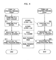
Embodiment 1 is explained.Figure 4 shows a flowchart that explains a behavior of the image forming apparatus in a starting process inEmbodiment 1. - At first, the
core 11a starts an unshown boot loader stored in a predetermined memory area, for example, in the flash memory 2 (Step S11). - The
core 11a starts the kernel of thecore 11a and the kernel of the core 11b using the boot loader (Steps S12 and S22). - Consequently, the
cores - The
core 11a mounts the root file system in accordance with the kernel (Step S13). Afterward, thecore 11a mounts a panel program area to a predetermined lower directory such as /usr/local in accordance with the kernel (Step S14). - On the other hand, the core 11b mounts the root file system in accordance with the kernel (Step S23). Afterward, the core 11b mounts a main program area to a predetermined lower directory such as /usr/local in accordance with the kernel (Step S24).
- In the aforementioned manner, the root file system in the
flash memory 2 is accessed (read only) by both thecores flash memory 2 is accessed (read and write) by only thecore 11a among thecores flash memory 2 is accessed (read and write) by only the core 11b among thecores - In the
aforementioned Embodiment 1, the image forming apparatus includes (a) theprocessor 1 including theplural cores flash memory 2 in which the shared file system to be mounted by both the kernel of thecore 11a and the kernel of the core 11b has been stored. - Therefore, since one root file system is shared, the size of a memory area required to the
flash memory 2 is small. - The image forming apparatus in
Embodiment 2 of this disclosure includes a hardware configuration similar to that of the image forming apparatus inEmbodiment 1. InEmbodiment 2, thecore 11a loads the root file system to theDRAM 3, and mounts the root file system loaded to theDRAM 3; and the core 11b does not load the root file system to theDRAM 3, and mounts the root file system loaded by thecore 11a to theDRAM 3. -
Figure 5 shows a diagram which indicates an example of memory areas allocated in theDRAM 3 inEmbodiment 2. - As shown in
Figure 5 , inEmbodiment 2, the root file system is loaded to an outside area of areas managed by the kernel of thecore 11a and the kernel of the core 11b in theDRAM 3; and the kernels of thecores - Specifically, the
core 11a loads the root file system to an outside area of areas managed by the kernels of thecores DRAM 3 using a boot loader, and then starts the kernel of thecore 11a and the kernel of the core 11b. - In the following part, a behavior of the image forming apparatus in a starting process in
Embodiment 2 is explained.Figure 6 shows a flowchart that explains a behavior of the image forming apparatus in a starting process inEmbodiment 2. - At first, the
core 11a starts an unshown boot loader stored in a predetermined memory area, for example, in the flash memory 2 (Step S31). For instance, u-boot is used as this boot loader. - The
core 11a loads the root file system from theflash memory 2 to a predetermined physical address area in theDRAM 3 in accordance with the boot loader (Step S32). - The
core 11a starts the kernel of thecore 11a and the kernel of the core 11b in accordance with the boot loader (Steps S33 and S43). - Consequently, the
cores - The
core 11a performs mapping the physical address area where the root file system was loaded to a logical address area, for example, using io_remap function in accordance with the kernel (Step S34), and generates and registers a memory block device (here, an MTD device) of this area (Step S35). Thecore 11a mounts the memory block device (i.e. the root file system) in accordance with the kernel (Step S36). Afterward, thecore 11a mounts the panel program area to a predetermined lower directory such as /usr/local in accordance with the kernel (Step S37). - On the other hand, the
core 11b performs mapping the physical address area where the root file system was loaded to a logical address area, for example, using io_remap function in accordance with the kernel (Step S44), and generates and registers a memory block device (here, an MTD device) of this area (Step S45). The core 11b mounts the memory block device (i.e. the root file system) in accordance with the kernel (Step S46). Afterward, the core 11b mounts the main program area to a predetermined lower directory such as /usr/local in accordance with the kernel (Step S47). - Information on the position of the physical address area where the root file system was loaded (e.g. the top address and the size) is provided to the kernels of the
cores - In the aforementioned manner, the root file system loaded in the
DRAM 3 is accessed by both thecores flash memory 2 is accessed by only thecore 11a among thecores flash memory 2 is accessed by only the core 11b among thecores - Other parts in the configuration of the image forming apparatus in
Embodiment 2 is identical to those inEmbodiment 1, and therefore, not explained here. - In the
aforementioned Embodiment 2, thecore 11a loads the root file system to theDRAM 3, and mounts the root file system loaded in theDRAM 3. Contrary to this, the core 11b mounts the root file system loaded by thecore 11a in theDRAM 3. - Therefore, since one root file system is shared, the size of a memory area required to the
flash memory 2 is small. Further, since the root file system loaded in theDRAM 3 is used, data read and data write to the root file system in theDRAM 3 can be performed faster than those in theflash memory 2. Furthermore, inEmbodiment 2, since this root file system includes only read-only data and/or a read-only program, the root file system is never changed. Therefore, after finishing using the root file system loaded in theDRAM 3, it is not necessary to write the root file system from theDRAM 3 back to theflash memory 2. - The description of the present invention has been presented for purposes of illustration and description, and is not intended to be exhaustive or limited to the invention in the form disclosed.
- For example, in
Embodiments plural cores processor 1. Alternatively, the plural processing units may be formed by plural processors connected via a bus or the like. - Further, in
Embodiments core 11a is used for the panel system. Alternatively, the image forming apparatus may includes a network interface, and thecore 11a may perform a communication process using this network interface. - Furthermore, in
Embodiments core 11a and/or the area managed by the kernel of the core 11b. In this case, the kernel managing area and the area of the memory block device must not be overlapped to each other. It should be noted that in general, io_remap function can not map a lower address than the top address of the kernel managing area (it results in an error to protect the kernel managing area), and therefore, in this case, io_remap function is modified to enable the modified io_remap function to map a lower address than the top address of the kernel managing area.Figure 7 shows a diagram which indicates another example of memory areas allocated in theDRAM 3 inEmbodiment 2. As shown inFigure 7 , for example, the memory block device can be allocated in a lower address than the kernel managing area of the core 11b. - Furthermore, in
Embodiments core 11a may generate a RAM disk in the kernel managing area of thecore 11a, load the panel program to the RAM disk, and mount the RAM disk instead of the panel program area included in theflash memory 2. Similarly, the kernel of the core 11b may generate a RAM disk in the kernel managing area of thecore 11a, load the main program to the RAM disk, and mount the RAM disk instead of the main program area included in theflash memory 2. - It should be understood that various changes and modifications to the embodiments described herein will be apparent to those skilled in the art. Such changes and modifications may be made without departing from the spirit and scope of the present subject matter and without diminishing its intended advantages. It is therefore intended that such changes and modifications be covered by the appended claims.
Claims (16)
- An image forming apparatus, comprising:a first processing unit (11a);a second processing unit (11b) configured to perform a process different from a process performed by the first processing unit (11a); anda non volatile memory device (2) in which a shared root file system has been stored, the shared root file system mounted by a kernel for the first processing unit (11a) and a kernel for the second processing unit (11b).
- The image forming apparatus according to claim 1, wherein:the shared root file system does not include any data and/or any programs to be rewritten by the first processing unit (11a) and the second processing unit (11b).
- The image forming apparatus according to claim 2, wherein:the non volatile memory device (2) comprises a first memory area in which data and/or a program to be rewritten by the first processing unit (11a) have been stored, and a second memory area in which data and/or a program to be rewritten by the second processing unit (11b) have been stored;the first memory area is configured to be mounted by the kernel of the first processing unit (11a); andthe second memory area is configured to be mounted by the kernel of the second processing unit (11b).
- The image forming apparatus according to any one of claims 1 to 3, wherein:the second processing unit (11b) is further configured to perform a job management process; andthe first processing unit (11a) is further configured to perform a predetermined process other than the job management process.
- The image forming apparatus according to claim 4, further comprising:an operation panel (7); andwherein the first processing unit (11a) is further configured to perform a process to control the operation panel (7).
- The image forming apparatus according to claim 4, further comprising:a network interface; andwherein the first processing unit (11a) is further configured to perform a process of data communication using the network interface.
- The image forming apparatus according to any one of claims 1 to 6, wherein:the non volatile memory device (2) in which the kernels of the first processing unit (11a) and the second processing unit (11b) have been stored; andone of the first processing unit (11a) and the second processing unit (11b) is further configured to perform a boot loader to start both the kernel of the first processing unit (11a) and the kernel of the second processing unit (11b).
- The image forming apparatus according to claim 1, further comprising:a volatile memory (3); andwherein the first processing unit (11a) is further configured to load the shared root file system to the volatile memory (3) and to mount the shared root file system loaded to the volatile memory (3); andthe second processing unit (11b) is further configured to mount the shared root file system loaded by the first processing unit (11a) to the volatile memory (3).
- The image forming apparatus according to claim 8, wherein:the shared root file system is further configured to be loaded to an outside area of areas managed by the kernel of the first processing unit (11a) and the kernel of the second processing unit (11b) in the volatile memory (3).
- The image forming apparatus according to claim 9, wherein:the first processing unit (11a) and the second processing unit (11b) are further configured to manage a memory area where the shared root file system was loaded as a memory block device.
- The image forming apparatus according to claim 9 or claim 10, wherein:one of the first processing unit (11a) and the second processing unit (11b) is configured to load the shared root file system to an outside area of areas managed by the kernel of the first processing unit (11a) and the kernel of the second processing unit (11a) in the volatile memory (3) using a boot loader, and to start the kernel of the first processing unit (11a) and the kernel of the second processing unit (11b) after loading the shared root file system.
- The image forming apparatus according to claim 10 or claim 11, wherein:the memory block device of the shared root file system is configured to be enabled to be in an address area after the area managed by the kernel of the first processing unit (11a) and/or the area managed by the kernel of the second processing unit (11b).
- The image forming apparatus according to any one of claims 10 to 12, wherein:the memory block device is an MTD device.
- The image forming apparatus according to any one of claims 1 to 13, wherein:a program in the shared root file system is described to acquire an ID of a processing unit that is executing this program, and to perform a process corresponding to the acquired ID.
- The image forming apparatus according to any one of claims 1 to 14, further comprising:a multiple core processor (1); andwherein the first processing unit (11a) and the second processing unit (11b) are any two of plural cores in the multiple core processor (1).
- The image forming apparatus according to any one of claims 1 to 15, wherein:the non volatile memory device (2) is a flash memory.
Applications Claiming Priority (3)
| Application Number | Priority Date | Filing Date | Title |
|---|---|---|---|
| JP2011285146 | 2011-12-27 | ||
| JP2011285147 | 2011-12-27 | ||
| JP2012145815A JP5746100B2 (en) | 2011-12-27 | 2012-06-28 | Image forming apparatus |
Publications (1)
| Publication Number | Publication Date |
|---|---|
| EP2611129A1 true EP2611129A1 (en) | 2013-07-03 |
Family
ID=47562911
Family Applications (1)
| Application Number | Title | Priority Date | Filing Date |
|---|---|---|---|
| EP12008200.3A Ceased EP2611129A1 (en) | 2011-12-27 | 2012-12-07 | Image forming apparatus |
Country Status (4)
| Country | Link |
|---|---|
| US (1) | US8970884B2 (en) |
| EP (1) | EP2611129A1 (en) |
| JP (1) | JP5746100B2 (en) |
| CN (1) | CN103198450B (en) |
Cited By (2)
| Publication number | Priority date | Publication date | Assignee | Title |
|---|---|---|---|---|
| EP2879051B1 (en) * | 2013-11-28 | 2018-08-15 | Kyocera Document Solutions Inc. | An electronic device including a MTD used temporarily during non-volatile memory file system update |
| US11934680B2 (en) * | 2020-02-06 | 2024-03-19 | Arris Enterprises Llc | Systems and methods for booting from NAND flash using squashfs to maximize memory |
Families Citing this family (19)
| Publication number | Priority date | Publication date | Assignee | Title |
|---|---|---|---|---|
| US9749548B2 (en) | 2015-01-22 | 2017-08-29 | Google Inc. | Virtual linebuffers for image signal processors |
| JP6287923B2 (en) * | 2015-03-26 | 2018-03-07 | コニカミノルタ株式会社 | Apparatus, program, recording medium storing program, and method for causing multi-core processor to execute task |
| US9965824B2 (en) | 2015-04-23 | 2018-05-08 | Google Llc | Architecture for high performance, power efficient, programmable image processing |
| US9756268B2 (en) | 2015-04-23 | 2017-09-05 | Google Inc. | Line buffer unit for image processor |
| US10095479B2 (en) | 2015-04-23 | 2018-10-09 | Google Llc | Virtual image processor instruction set architecture (ISA) and memory model and exemplary target hardware having a two-dimensional shift array structure |
| US9785423B2 (en) | 2015-04-23 | 2017-10-10 | Google Inc. | Compiler for translating between a virtual image processor instruction set architecture (ISA) and target hardware having a two-dimensional shift array structure |
| US9769356B2 (en) | 2015-04-23 | 2017-09-19 | Google Inc. | Two dimensional shift array for image processor |
| US9772852B2 (en) | 2015-04-23 | 2017-09-26 | Google Inc. | Energy efficient processor core architecture for image processor |
| US10291813B2 (en) | 2015-04-23 | 2019-05-14 | Google Llc | Sheet generator for image processor |
| US9830150B2 (en) | 2015-12-04 | 2017-11-28 | Google Llc | Multi-functional execution lane for image processor |
| US10313641B2 (en) | 2015-12-04 | 2019-06-04 | Google Llc | Shift register with reduced wiring complexity |
| US10387988B2 (en) | 2016-02-26 | 2019-08-20 | Google Llc | Compiler techniques for mapping program code to a high performance, power efficient, programmable image processing hardware platform |
| US10204396B2 (en) | 2016-02-26 | 2019-02-12 | Google Llc | Compiler managed memory for image processor |
| US10380969B2 (en) | 2016-02-28 | 2019-08-13 | Google Llc | Macro I/O unit for image processor |
| US20180005059A1 (en) | 2016-07-01 | 2018-01-04 | Google Inc. | Statistics Operations On Two Dimensional Image Processor |
| US20180005346A1 (en) | 2016-07-01 | 2018-01-04 | Google Inc. | Core Processes For Block Operations On An Image Processor Having A Two-Dimensional Execution Lane Array and A Two-Dimensional Shift Register |
| US10546211B2 (en) | 2016-07-01 | 2020-01-28 | Google Llc | Convolutional neural network on programmable two dimensional image processor |
| US20180007302A1 (en) | 2016-07-01 | 2018-01-04 | Google Inc. | Block Operations For An Image Processor Having A Two-Dimensional Execution Lane Array and A Two-Dimensional Shift Register |
| US10909165B2 (en) | 2017-06-20 | 2021-02-02 | Red Hat, Inc. | Sharing filesystems between containers |
Citations (7)
| Publication number | Priority date | Publication date | Assignee | Title |
|---|---|---|---|---|
| EP1482720A1 (en) * | 2003-05-28 | 2004-12-01 | Ricoh Company, Ltd. | Image processing apparatus and computer product |
| US20060195715A1 (en) * | 2005-02-28 | 2006-08-31 | Herington Daniel E | System and method for migrating virtual machines on cluster systems |
| US20080244577A1 (en) * | 2007-03-29 | 2008-10-02 | Vmware, Inc. | Software delivery for virtual machines |
| US20080271017A1 (en) * | 2007-04-30 | 2008-10-30 | Dan Herington | Managing Virtual Machines Using Shared Image |
| US20090037680A1 (en) * | 2007-07-31 | 2009-02-05 | Vmware, Inc. | Online virtual machine disk migration |
| US20090249331A1 (en) * | 2008-03-31 | 2009-10-01 | Mark Charles Davis | Apparatus, system, and method for file system sharing |
| US20100058106A1 (en) * | 2008-08-27 | 2010-03-04 | Novell, Inc. | Virtual machine file system and incremental snapshot using image deltas |
Family Cites Families (11)
| Publication number | Priority date | Publication date | Assignee | Title |
|---|---|---|---|---|
| US20040083357A1 (en) * | 2002-10-29 | 2004-04-29 | Sun Microsystems, Inc. | Method, system, and program for executing a boot routine on a computer system |
| US7603528B2 (en) * | 2004-10-08 | 2009-10-13 | International Business Machines Corporation | Memory device verification of multiple write operations |
| US7765548B2 (en) * | 2005-02-17 | 2010-07-27 | Red Hat, Inc. | System, method and medium for using and/or providing operating system information to acquire a hybrid user/operating system lock |
| JP4011082B2 (en) * | 2005-11-08 | 2007-11-21 | 株式会社ソニー・コンピュータエンタテインメント | Information processing apparatus, graphic processor, control processor, and information processing method |
| JP4949889B2 (en) | 2007-02-21 | 2012-06-13 | 株式会社リコー | Sub-control device and information processing device |
| JP5487725B2 (en) * | 2009-05-26 | 2014-05-07 | 株式会社リコー | Information processing apparatus, information processing method, and information processing program |
| JP5035299B2 (en) * | 2009-06-15 | 2012-09-26 | 株式会社日立製作所 | Multi-core processor control method, computer system thereof, and management computer program |
| JP2011192131A (en) * | 2010-03-16 | 2011-09-29 | Fuji Xerox Co Ltd | Control device, image forming apparatus, and control program |
| JP2011203843A (en) * | 2010-03-24 | 2011-10-13 | Kyocera Mita Corp | Information processing apparatus |
| JP4735765B2 (en) * | 2010-07-26 | 2011-07-27 | 日本ビクター株式会社 | Linux program startup system |
| US8893306B2 (en) * | 2010-08-31 | 2014-11-18 | International Business Machines Corporation | Resource management and security system |
-
2012
- 2012-06-28 JP JP2012145815A patent/JP5746100B2/en not_active Expired - Fee Related
- 2012-12-05 CN CN201210517484.8A patent/CN103198450B/en not_active Expired - Fee Related
- 2012-12-07 EP EP12008200.3A patent/EP2611129A1/en not_active Ceased
- 2012-12-11 US US13/711,379 patent/US8970884B2/en not_active Expired - Fee Related
Patent Citations (7)
| Publication number | Priority date | Publication date | Assignee | Title |
|---|---|---|---|---|
| EP1482720A1 (en) * | 2003-05-28 | 2004-12-01 | Ricoh Company, Ltd. | Image processing apparatus and computer product |
| US20060195715A1 (en) * | 2005-02-28 | 2006-08-31 | Herington Daniel E | System and method for migrating virtual machines on cluster systems |
| US20080244577A1 (en) * | 2007-03-29 | 2008-10-02 | Vmware, Inc. | Software delivery for virtual machines |
| US20080271017A1 (en) * | 2007-04-30 | 2008-10-30 | Dan Herington | Managing Virtual Machines Using Shared Image |
| US20090037680A1 (en) * | 2007-07-31 | 2009-02-05 | Vmware, Inc. | Online virtual machine disk migration |
| US20090249331A1 (en) * | 2008-03-31 | 2009-10-01 | Mark Charles Davis | Apparatus, system, and method for file system sharing |
| US20100058106A1 (en) * | 2008-08-27 | 2010-03-04 | Novell, Inc. | Virtual machine file system and incremental snapshot using image deltas |
Non-Patent Citations (3)
| Title |
|---|
| "Hypervisor", 22 December 2011 (2011-12-22), XP055169020, Retrieved from the Internet <URL:http://en.wikipedia.org/w/index.php?title=Hypervisor&oldid=467140588> [retrieved on 20150211] * |
| "Root Filesystem Definition", 18 April 2006 (2006-04-18), XP055054587, Retrieved from the Internet <URL:http://www.linfo.org/root_filesystem.html> [retrieved on 20130226] * |
| M. TIM JONES: "Inside the Linux boot process", DEVELOPERWORKS, 31 May 2006 (2006-05-31), XP055054580, Retrieved from the Internet <URL:http://www.ibm.com/developerworks/linux/library/l-linuxboot/l-linuxboot-pdf.pdf> [retrieved on 20130226] * |
Cited By (2)
| Publication number | Priority date | Publication date | Assignee | Title |
|---|---|---|---|---|
| EP2879051B1 (en) * | 2013-11-28 | 2018-08-15 | Kyocera Document Solutions Inc. | An electronic device including a MTD used temporarily during non-volatile memory file system update |
| US11934680B2 (en) * | 2020-02-06 | 2024-03-19 | Arris Enterprises Llc | Systems and methods for booting from NAND flash using squashfs to maximize memory |
Also Published As
| Publication number | Publication date |
|---|---|
| US20130163040A1 (en) | 2013-06-27 |
| JP2013152695A (en) | 2013-08-08 |
| CN103198450A (en) | 2013-07-10 |
| JP5746100B2 (en) | 2015-07-08 |
| US8970884B2 (en) | 2015-03-03 |
| CN103198450B (en) | 2015-12-23 |
Similar Documents
| Publication | Publication Date | Title |
|---|---|---|
| US8970884B2 (en) | Image forming apparatus | |
| US10055218B2 (en) | System and method for adding and storing groups of firmware default settings | |
| CN101149688B (en) | Virtualization system and its memory management method | |
| US9454397B2 (en) | Data processing systems | |
| CN107209683B (en) | Backup image recovery | |
| EP2477111A2 (en) | Computer system and program restoring method thereof | |
| US12067380B2 (en) | System and method of offloading and migrating management controller functionalities using containerized services and application thereof | |
| CN106796507A (en) | The multiple operating system environment in computing device is supported without Content Transformation | |
| US10474494B2 (en) | Information processing apparatus, information processing method, and computer program product | |
| US9858229B2 (en) | Data access protection for computer systems | |
| KR20200042798A (en) | Method for controlling the execution of different operating systems, electronic device and storage medium therefor | |
| US11836503B2 (en) | Electronic device for executing heterogeneous operating systems and method therefor | |
| US7886095B2 (en) | I/O space request suppressing method for PCI device | |
| JP2011060225A (en) | Operating system booting method | |
| EP3123388B1 (en) | Virtualization based intra-block workload isolation | |
| CN114168180A (en) | Updating method, computing device, electronic device and storage medium | |
| CN110471744B (en) | Password modification method, device, equipment and computer readable storage medium | |
| US11237741B2 (en) | Electronic device and control method for controlling memory | |
| US20060075158A1 (en) | Information processing apparatus and data transfer control method | |
| US12591369B2 (en) | Node cache migration | |
| US10951787B2 (en) | Information processing apparatus that controls timing for enabling an application, control method of information processing apparatus, and recording medium | |
| JP2019160133A (en) | Information processing device, information processing system, and method | |
| US20120284711A1 (en) | Method and Arrangement for Configuring a Resource for a Virtual Runtime Environment | |
| US11829670B2 (en) | Information processing apparatus and control method for information processing apparatus | |
| JP2011203843A (en) | Information processing apparatus |
Legal Events
| Date | Code | Title | Description |
|---|---|---|---|
| PUAI | Public reference made under article 153(3) epc to a published international application that has entered the european phase |
Free format text: ORIGINAL CODE: 0009012 |
|
| AK | Designated contracting states |
Kind code of ref document: A1 Designated state(s): AL AT BE BG CH CY CZ DE DK EE ES FI FR GB GR HR HU IE IS IT LI LT LU LV MC MK MT NL NO PL PT RO RS SE SI SK SM TR |
|
| AX | Request for extension of the european patent |
Extension state: BA ME |
|
| 17P | Request for examination filed |
Effective date: 20131108 |
|
| RBV | Designated contracting states (corrected) |
Designated state(s): AL AT BE BG CH CY CZ DE DK EE ES FI FR GB GR HR HU IE IS IT LI LT LU LV MC MK MT NL NO PL PT RO RS SE SI SK SM TR |
|
| 17Q | First examination report despatched |
Effective date: 20140307 |
|
| APBK | Appeal reference recorded |
Free format text: ORIGINAL CODE: EPIDOSNREFNE |
|
| APBN | Date of receipt of notice of appeal recorded |
Free format text: ORIGINAL CODE: EPIDOSNNOA2E |
|
| APBR | Date of receipt of statement of grounds of appeal recorded |
Free format text: ORIGINAL CODE: EPIDOSNNOA3E |
|
| APAF | Appeal reference modified |
Free format text: ORIGINAL CODE: EPIDOSCREFNE |
|
| APAF | Appeal reference modified |
Free format text: ORIGINAL CODE: EPIDOSCREFNE |
|
| APBT | Appeal procedure closed |
Free format text: ORIGINAL CODE: EPIDOSNNOA9E |
|
| STAA | Information on the status of an ep patent application or granted ep patent |
Free format text: STATUS: THE APPLICATION HAS BEEN REFUSED |
|
| 18R | Application refused |
Effective date: 20210818 |