EP2610922A2 - Photovoltaic module and frame thereof - Google Patents
Photovoltaic module and frame thereof Download PDFInfo
- Publication number
- EP2610922A2 EP2610922A2 EP12187053.9A EP12187053A EP2610922A2 EP 2610922 A2 EP2610922 A2 EP 2610922A2 EP 12187053 A EP12187053 A EP 12187053A EP 2610922 A2 EP2610922 A2 EP 2610922A2
- Authority
- EP
- European Patent Office
- Prior art keywords
- cross
- wind tunnel
- sectional area
- tunnel structure
- wall
- Prior art date
- Legal status (The legal status is an assumption and is not a legal conclusion. Google has not performed a legal analysis and makes no representation as to the accuracy of the status listed.)
- Granted
Links
Images



Classifications
-
- H—ELECTRICITY
- H10—SEMICONDUCTOR DEVICES; ELECTRIC SOLID-STATE DEVICES NOT OTHERWISE PROVIDED FOR
- H10F—INORGANIC SEMICONDUCTOR DEVICES SENSITIVE TO INFRARED RADIATION, LIGHT, ELECTROMAGNETIC RADIATION OF SHORTER WAVELENGTH OR CORPUSCULAR RADIATION
- H10F77/00—Constructional details of devices covered by this subclass
- H10F77/60—Arrangements for cooling, heating, ventilating or compensating for temperature fluctuations
- H10F77/63—Arrangements for cooling directly associated or integrated with photovoltaic cells, e.g. heat sinks directly associated with the photovoltaic cells or integrated Peltier elements for active cooling
- H10F77/68—Arrangements for cooling directly associated or integrated with photovoltaic cells, e.g. heat sinks directly associated with the photovoltaic cells or integrated Peltier elements for active cooling using gaseous or liquid coolants, e.g. air flow ventilation or water circulation
-
- H—ELECTRICITY
- H02—GENERATION; CONVERSION OR DISTRIBUTION OF ELECTRIC POWER
- H02S—GENERATION OF ELECTRIC POWER BY CONVERSION OF INFRARED RADIATION, VISIBLE LIGHT OR ULTRAVIOLET LIGHT, e.g. USING PHOTOVOLTAIC [PV] MODULES
- H02S30/00—Structural details of PV modules other than those related to light conversion
- H02S30/10—Frame structures
-
- F—MECHANICAL ENGINEERING; LIGHTING; HEATING; WEAPONS; BLASTING
- F24—HEATING; RANGES; VENTILATING
- F24S—SOLAR HEAT COLLECTORS; SOLAR HEAT SYSTEMS
- F24S25/00—Arrangement of stationary mountings or supports for solar heat collector modules
- F24S25/20—Peripheral frames for modules
-
- Y—GENERAL TAGGING OF NEW TECHNOLOGICAL DEVELOPMENTS; GENERAL TAGGING OF CROSS-SECTIONAL TECHNOLOGIES SPANNING OVER SEVERAL SECTIONS OF THE IPC; TECHNICAL SUBJECTS COVERED BY FORMER USPC CROSS-REFERENCE ART COLLECTIONS [XRACs] AND DIGESTS
- Y02—TECHNOLOGIES OR APPLICATIONS FOR MITIGATION OR ADAPTATION AGAINST CLIMATE CHANGE
- Y02E—REDUCTION OF GREENHOUSE GAS [GHG] EMISSIONS, RELATED TO ENERGY GENERATION, TRANSMISSION OR DISTRIBUTION
- Y02E10/00—Energy generation through renewable energy sources
- Y02E10/50—Photovoltaic [PV] energy
Definitions
- Embodiments of the present invention relate to a photovoltaic module. More particularly, embodiments of the present invention relate to a photovoltaic module, and to a frame of the photovoltaic module.
- a photovoltaic panel In a conventional photovoltaic module, a photovoltaic panel is held in a frame fixed on the rooftop of a building.
- the frame for holding the photovoltaic panel has a poor heat dissipating ability, and therefore, the temperature of the photovoltaic panel may be higher than the ambient temperature by about 30-50 °C. Further, the efficiency of the photovoltaic module may be lowered by about 5% for every 10 °C increase in the temperature of the photovoltaic module. Hence, this poor ability to dissipate heat lowers the efficiency of the photovoltaic module.
- a frame of a photovoltaic module is provided.
- the frame is used for holding a photovoltaic panel, and includes a holding part and an extending part.
- the holding part is used for holding the photovoltaic panel.
- the extending part is connected to the holding part and includes at least one first wind tunnel structure, in which the cross-sectional area of an inlet of the first wind tunnel structure is greater than the cross-sectional area of an outlet of the first wind tunnel structure.
- a photovoltaic module in accordance with another embodiment of the present invention, includes a photovoltaic panel and a frame.
- the frame includes a holding part and an extending part.
- the holding part holds the photovoltaic panel.
- the extending part is connected to the holding part and includes at least one first wind tunnel structure, in which the cross-sectional area of an inlet of the first wind tunnel structure is greater than the cross-sectional area of an outlet of the first wind tunnel structure.
- Fig. 1 is a cross-sectional view of a frame of a photovoltaic module in accordance with one embodiment of the present invention.
- the frame may be used for holding a photovoltaic panel 600, and includes a holding part 100 and an extending part 200.
- the holding part 100 is used for holding the photovoltaic panel 600.
- the extending part 200 is connected to the holding part 100, and includes at least one first wind tunnel structure 300 having an inlet 310 and an outlet 320.
- the cross-sectional area of the inlet 310 of the first wind tunnel structure 300 is greater than the cross-sectional area of the outlet 320 of the first wind tunnel structure 300.
- the extending part 200 can be fastened on a home, building, etc. so as to secure the photovoltaic panel 600 to the home, building, etc.
- the embodiment of the present invention employs the first wind tunnel structure 300 to guide the airflow blowing over the undersurface of the photovoltaic panel 600, thereby dissipating heat accumulating under the photovoltaic panel 600. Therefore, the inlet 310 is formed in the outer surface of the frame which is far away from the photovoltaic panel 600, while the outlet 320 is formed in the inner surface of the frame which is closer to the photovoltaic panel 600.
- the extending part 200 of the frame of the photovoltaic module may include an outer wall 210 and an inner wall 220.
- An intake 212 is formed in the outer wall 210, and a vent 222 is formed in the inner wall 220.
- the extending part 200 may be a hollow structure with a pair of walls. In this case, one wall that is closer to the photovoltaic panel 600 is the inner wall 220, and the other wall that is far away from the photovoltaic panel 600 is the outer wall 210, and a space is formed between the outer wall 210 and the inner wall 220.
- the intake 212 can be formed in the outer wall 210, and the vent 222 can be formed in the inner wall 220.
- the cross-sectional area of the intake 212 is greater than the cross-sectional area of the vent 222, so that the airflow can be accelerated and the heat dissipating ability can be promoted.
- the intake 212 and the vent 222 may include, but is not limited to including, a circular, elliptical, rectangular, polygonal, or arbitrarily shaped opening.
- the extending part 200 may be a solid structure.
- the inlet 310 of the first wind tunnel structure 300 may be the intake 212 formed in the outer wall 210 of the extending part 200, and the outlet 320 of the first wind tunnel structure 300 may be the vent 222 formed in the inner wall 220 of the extending part 200.
- the cross-sectional area of the intake 212 is greater than the cross-sectional area of the vent 222. With these equivalents in mind, therefore, the cross-sectional area of the inlet 310 of the first wind tunnel structure 300 is greater than the cross-sectional area of the outlet 320.
- the airflow velocity at the outlet 320 is greater than the airflow velocity at the inlet 310.
- the variation of these cross-sectional areas may accelerate the airflow and thereby improves the heat dissipating ability.
- the extending part 200 can be divided by the first wind tunnel structure 300 into an upper extending part 202 and a lower extending part 204.
- the outer wall 210 of the upper extending part 202 and the outer wall 210 of the lower extending part 204 define the height of the intake 212.
- the inner wall 220 of the upper extending part 202 and the inner wall 220 of the lower extending part 204 define the height of the vent 222.
- the height of the intake 212 is greater than the height of the vent 222, so as to make the cross-sectional area of the intake 212 greater than the cross-sectional area 222 of the vent 222, thereby accelerating airflow and improving heat dissipating ability.
- Fig. 2 is a cross-sectional view of the extending part 200 of the frame shown in Fig. 1 , in which the direction of cross-section is perpendicular to the direction of cross-section of Fig. 1 .
- the extending part 200 can be further divided by the first wind tunnel structure 300 into a left extending part 206 and a right extending part 208.
- the left extending part 206 and the right extending part 208 both have an outer wall 210 and an inner wall 220, in which the outer wall 210 and the inner wall 220 are spatially separated.
- the outer wall 210 of the left extending part 206 and the outer wall 210 of the right extending part 208 define the width of the intake 212.
- the inner wall 220 of the left extending part 206 and the inner wall 220 of the right extending part 208 define the width of the vent 222.
- the width of the intake 212 is greater than the width of the vent 222, so as to make the cross-sectional area of the intake 212 greater than the cross-sectional area of the vent 222 and similarly make the cross-sectional area of the inlet 310 of the first wind tunnel structure 300 greater than the cross-sectional area of the outlet 320, thereby accelerating airflow and improving heat dissipating ability.
- the intake 212 and the vent 222 may both be circular, and the radius of the intake 212 may be greater than the radius of the vent 222, so as to make the cross-sectional area of the intake 212 greater than the cross-sectional area of the vent 222, thereby accelerating airflow and improving the heat dissipating ability.
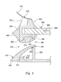
- Fig. 3 is a cross-sectional view of a frame of a photovoltaic module in accordance with another embodiment of the present invention.
- the frame may further include at least one flow guiding structure 400 connected to the intake 212 and the vent 222.
- the flow guiding structure 400 crosses over the space formed between the outer wall 210 and the inner wall 220 of the extending part 200 and interconnects the outer wall 210 and the inner wall 220, so as to guide airflow towards the photovoltaic panel 600.
- the flow guiding structure 400 is extended out of the outer wall 210. Specifically, the flow guiding structure 400 can be extended from the inner wall 220 to the outer wall 210 and further extended outside the outer wall 210. In some embodiments, the flow guiding structure 400 can be streamlined, so as to facilitate airflow moving towards the photovoltaic panel 600.
- the flow guiding structure 400 has a windward opening 410, in which the cross-sectional area of the windward opening 410 is greater than the cross-sectional area of the intake 212.
- the opening of the flow guiding structure 400 expands gradually along the direction away from the outer wall 210.
- the flow guiding structure 400 disposed on the upper extending part 202 extends upwardly along the direction away from the outer wall 210.
- the flow guiding structure 400 disposed on the lower extending part 204 extends downwardly along the direction away from the outer wall 210.
- Fig. 4 is a cross-sectional view of the extending part 200 of the frame shown in Fig. 3 , in which the direction of cross-section is perpendicular to direction of cross-section employed in Fig. 3 .
- the flow guiding structure 400 disposed on the left extending part 206 extends leftward along the direction away from the outer wall 210. Contrarily, the flow guiding structure 400 extends rightward along the direction away from the outer wall 210. Therefore, the cross-sectional area of the flow guiding structure 400 increases gradually along the direction away from the outer wall 210, so that the cross-sectional area of the windward opening 410 can be greater than the cross-sectional area of the intake 212.
- the flow guiding structure 400 can be made of a plastic material.
- the flow guiding structure 400 can be made of a thermoplastic material, such as TPE (Thermoplastic Elastomer).
- the flow guiding structure 400 can be made of metal, such as aluminum, iron, stainless steel, or combinations thereof.
- the frame of the photovoltaic module may further include a second wind tunnel structure 500 disposed on the holding part 100.
- the second wind tunnel structure 500 is disposed on a side of the holding part 100 that is opposite the side thereof to which the extending part 200 is connected.
- Fig. 5 is a partial side view of the frame of the photovoltaic module shown in Fig. 3 .
- Fig. 6 is a partial top view of the frame of the photovoltaic module shown in Fig. 3 .
- the second wind tunnel structure 500 includes a plurality of inlets 550 and a plurality of outlets 560 so as to guide airflow towards an upper surface of the photovoltaic panel 600, thereby dissipating the heat energy accumulating above the photovoltaic panel 600.
- the second wind tunnel structure 500 may comprise a flow guiding sheet 510 and a plurality of supports 520 supporting the flow guiding sheet 510.
- the flow guiding sheet 510 and the supports 520 may define a plurality of inlets 550 and a plurality of outlets 560 (see Fig. 6 ).
- the flow guiding sheet 510 is supported by numerous supports 520, and these supports 520 are disposed on the holding part 100 and spatially separated from each other.
- Adjacent supports 520 define a cavity 540 therebetween.
- the entrance of the cavity 540 for the intake of airflow defines the inlet 550 (see Fig. 6 ), and the vent of the cavity 540 for exhausting airflow defines the outlet 560 (see Fig. 6 ).
- the cross-sectional area of the inlet 550 of the second wind tunnel structure 500 is greater than the cross-sectional area of the outlet 560 of the second wind tunnel structure 500.
- each of the supports 520 includes a windward surface 522 and a leeward surface 524.
- the cross-sectional area of the windward surface 522 is less than the cross-sectional area of the leeward surface 524. Because each of the inlets 550 is formed between the windward surfaces 522 of pair of adjacent supports 520, and the outlet 560 is formed between the leeward surfaces 524 of a pair of adjacent supports 520, the cross-sectional area of the inlet 550 can be greater than the cross-sectional area of the outlet 560. Therefore, the velocity of the airflow passing through the outlet 560 is greater than the velocity of the airflow passing through the inlet 550, so that the second wind tunnel structure 500 can further accelerate airflow and improve heat dissipating ability.
- the photovoltaic panel 600 comprises at least one solar cell 620.
- An angle 530 is defined by the second wind tunnel structure 500 and the solar cell 620. Specifically, an imaginary connecting line is drawn between an edge of the upper surface of one of the supports 520 closest to the solar cell 620 and an edge of the upper surface of the solar cell 620 nearest to the support 520, and the angle 530 is defined between the upper surface of the photovoltaic panel 600 and the connecting line.
- the angle 530 is less than a particular angle to prevent the shadow of the support 520 from being projected onto the solar cell 620 and affecting the power generating efficiency. In one embodiment, the angle is less than 66.5 degrees.
- the flow guiding sheet 510 can include a reflective surface 570 facing the photovoltaic panel 600.
- the reflective surface 570 is substantially arc-shaped for concentrating light. In this case, light emitted onto the reflective surface 570 can be reflected to the photovoltaic panel 600, thereby increasing the amount of solar energy that the photovoltaic panel 600 receives.
- Fig. 7 is a perspective view of the photovoltaic module in accordance with one embodiment shown in Fig. 3 and a partial cross-sectional view of a frame thereof.
- the photovoltaic module includes a photovoltaic panel 600 and a frame 700.
- the frame 700 holds at least one side of the photovoltaic panel 600.
- the frame 700 is similar to the frame described in the aforementioned embodiments, and it includes a holding part 100 and an extending part 200.
- the holding part 100 comprising a concave is configured to hold the photovoltaic panel 600.
- the extending part 200 is connected to the holding part 100, and it includes at least one first wind tunnel structure 300.
- the cross-sectional area of the inlet 310 of the first wind tunnel structure 300 is greater than the cross-sectional area of the outlet 320 of the first wind tunnel structure 300.
- the upper extending part 202 is connected to the lower extending part 204.
- at least one first wind tunnel structure 300 is formed on the extending part 200, and the structure on a portion of the extending part 200 where the first wind tunnel structure 300 is not disposed is not cut away.
- the upper extending part 202 and the lower extending part 204 are connected on a portion of the extending part 200 where the first wind tunnel structure 300 is not located.
- the number of the first wind tunnel structures 300 can be determined by the strength of the frame 700 and the heat dissipation requirements.
- Embodiments of the present invention can accelerate airflow by using the difference between the cross-sectional area of the inlet 310 of the first wind tunnel structure 300 and the cross-sectional area of the outlet 320 of the first wind tunnel structure 300, so that the airflow can flow over the photovoltaic panel 600 in higher speed, thereby improving the heat dissipation ability.
Landscapes
- Photovoltaic Devices (AREA)
- Roof Covering Using Slabs Or Stiff Sheets (AREA)
Abstract
Description
- Embodiments of the present invention relate to a photovoltaic module. More particularly, embodiments of the present invention relate to a photovoltaic module, and to a frame of the photovoltaic module.
- In recent years, energy issues have been the focus of much attention. In order to solve the problems associated with using fuel sources to meet energy demands, a variety of alternative energy technologies have been developed. Because solar energy has many advantages, such as being non-polluting and unlimited, it is a popular choice to replace oil energy. Therefore, more and more photovoltaic panels are being disposed on homes, buildings, etc. at locations where there is abundant sunshine.
- In a conventional photovoltaic module, a photovoltaic panel is held in a frame fixed on the rooftop of a building. The frame for holding the photovoltaic panel has a poor heat dissipating ability, and therefore, the temperature of the photovoltaic panel may be higher than the ambient temperature by about 30-50 °C. Further, the efficiency of the photovoltaic module may be lowered by about 5% for every 10 °C increase in the temperature of the photovoltaic module. Hence, this poor ability to dissipate heat lowers the efficiency of the photovoltaic module.
- In accordance with one embodiment of the present invention, a frame of a photovoltaic module is provided. The frame is used for holding a photovoltaic panel, and includes a holding part and an extending part. The holding part is used for holding the photovoltaic panel. The extending part is connected to the holding part and includes at least one first wind tunnel structure, in which the cross-sectional area of an inlet of the first wind tunnel structure is greater than the cross-sectional area of an outlet of the first wind tunnel structure.
- In accordance with another embodiment of the present invention, a photovoltaic module is provided. The photovoltaic module includes a photovoltaic panel and a frame. The frame includes a holding part and an extending part. The holding part holds the photovoltaic panel. The extending part is connected to the holding part and includes at least one first wind tunnel structure, in which the cross-sectional area of an inlet of the first wind tunnel structure is greater than the cross-sectional area of an outlet of the first wind tunnel structure.
- The invention can be more fully understood by reading the following detailed description of the embodiment, with reference made to the accompanying drawings as follows:
-
Fig. 1 is a cross-sectional view of a frame of a photovoltaic module in accordance with one embodiment of the present invention; -
Fig. 2 is a cross-sectional view of an extending part of the frame shown inFig. 1 , in which the direction of cross-section is perpendicular to the direction of cross-section employed inFig. 1 ; -
Fig. 3 is a cross-sectional view of a frame of a photovoltaic module in accordance with another embodiment of the present invention; -
Fig. 4 is a cross-sectional view of an extending part of the frame shown inFig. 3 ; -
Fig. 5 is a partial side view of the frame of the photovoltaic module shown inFig. 3 ; -
Fig. 6 is a partial top view of the frame of the photovoltaic module shown inFig. 3 ; and -
Fig. 7 is a perspective view of the photovoltaic module in accordance with one embodiment shown inFig. 3 and a partial cross-sectional view of a frame thereof. - Reference will now be made in detail to the present embodiments of the invention, examples of which are illustrated in the accompanying drawings. Wherever possible, the same reference numbers are used in the drawings and the description to refer to the same or like parts.
-
Fig. 1 is a cross-sectional view of a frame of a photovoltaic module in accordance with one embodiment of the present invention. As shown in the figure, the frame may be used for holding aphotovoltaic panel 600, and includes aholding part 100 and an extendingpart 200. Theholding part 100 is used for holding thephotovoltaic panel 600. The extendingpart 200 is connected to theholding part 100, and includes at least one firstwind tunnel structure 300 having aninlet 310 and anoutlet 320. The cross-sectional area of theinlet 310 of the firstwind tunnel structure 300 is greater than the cross-sectional area of theoutlet 320 of the firstwind tunnel structure 300. Further, the extendingpart 200 can be fastened on a home, building, etc. so as to secure thephotovoltaic panel 600 to the home, building, etc. - Through aforementioned configuration, the embodiment of the present invention employs the first
wind tunnel structure 300 to guide the airflow blowing over the undersurface of thephotovoltaic panel 600, thereby dissipating heat accumulating under thephotovoltaic panel 600. Therefore, theinlet 310 is formed in the outer surface of the frame which is far away from thephotovoltaic panel 600, while theoutlet 320 is formed in the inner surface of the frame which is closer to thephotovoltaic panel 600. - In some embodiments, the extending
part 200 of the frame of the photovoltaic module may include anouter wall 210 and aninner wall 220. Anintake 212 is formed in theouter wall 210, and avent 222 is formed in theinner wall 220. For example, the extendingpart 200 may be a hollow structure with a pair of walls. In this case, one wall that is closer to thephotovoltaic panel 600 is theinner wall 220, and the other wall that is far away from thephotovoltaic panel 600 is theouter wall 210, and a space is formed between theouter wall 210 and theinner wall 220. Theintake 212 can be formed in theouter wall 210, and thevent 222 can be formed in theinner wall 220. The cross-sectional area of theintake 212 is greater than the cross-sectional area of thevent 222, so that the airflow can be accelerated and the heat dissipating ability can be promoted. For example, theintake 212 and thevent 222 may include, but is not limited to including, a circular, elliptical, rectangular, polygonal, or arbitrarily shaped opening. In some embodiments, the extendingpart 200 may be a solid structure. - In some embodiments, the
inlet 310 of the firstwind tunnel structure 300 may be theintake 212 formed in theouter wall 210 of the extendingpart 200, and theoutlet 320 of the firstwind tunnel structure 300 may be thevent 222 formed in theinner wall 220 of the extendingpart 200. The cross-sectional area of theintake 212 is greater than the cross-sectional area of thevent 222. With these equivalents in mind, therefore, the cross-sectional area of theinlet 310 of the firstwind tunnel structure 300 is greater than the cross-sectional area of theoutlet 320. - As shown in the figure, because the cross-sectional area of the
inlet 310 of the firstwind tunnel structure 300 is greater than the cross-sectional area of theoutlet 320, the airflow velocity at theoutlet 320 is greater than the airflow velocity at theinlet 310. The variation of these cross-sectional areas may accelerate the airflow and thereby improves the heat dissipating ability. - In some embodiments, the extending
part 200 can be divided by the firstwind tunnel structure 300 into an upper extendingpart 202 and a lower extendingpart 204. Theouter wall 210 of the upper extendingpart 202 and theouter wall 210 of the lower extendingpart 204 define the height of theintake 212. Similarly, theinner wall 220 of the upper extendingpart 202 and theinner wall 220 of the lower extendingpart 204 define the height of thevent 222. In this embodiment, the height of theintake 212 is greater than the height of thevent 222, so as to make the cross-sectional area of theintake 212 greater than thecross-sectional area 222 of thevent 222, thereby accelerating airflow and improving heat dissipating ability. -
Fig. 2 is a cross-sectional view of the extendingpart 200 of the frame shown inFig. 1 , in which the direction of cross-section is perpendicular to the direction of cross-section ofFig. 1 . As shown in this figure, the extendingpart 200 can be further divided by the firstwind tunnel structure 300 into aleft extending part 206 and a right extendingpart 208. The left extendingpart 206 and the right extendingpart 208 both have anouter wall 210 and aninner wall 220, in which theouter wall 210 and theinner wall 220 are spatially separated. Theouter wall 210 of the left extendingpart 206 and theouter wall 210 of the right extendingpart 208 define the width of theintake 212. Similarly, theinner wall 220 of theleft extending part 206 and theinner wall 220 of the right extendingpart 208 define the width of thevent 222. In this embodiment, the width of theintake 212 is greater than the width of thevent 222, so as to make the cross-sectional area of theintake 212 greater than the cross-sectional area of thevent 222 and similarly make the cross-sectional area of theinlet 310 of the firstwind tunnel structure 300 greater than the cross-sectional area of theoutlet 320, thereby accelerating airflow and improving heat dissipating ability. - It should be noted that the explanation of the differences in height or width of the
intake 212 and thevent 222 in the aforementioned embodiments is provided by way of example, and should not to limit the present invention. A feature of the embodiments described above relates to the fact that the cross-sectional area of theintake 212 is greater than the cross-sectional area of thevent 222. In other embodiments, the cross-sectional area of theintake 212 can be greater than the cross-sectional area of thevent 222 by using other configurations. For example, theintake 212 and thevent 222 may both be circular, and the radius of theintake 212 may be greater than the radius of thevent 222, so as to make the cross-sectional area of theintake 212 greater than the cross-sectional area of thevent 222, thereby accelerating airflow and improving the heat dissipating ability. -
Fig. 3 is a cross-sectional view of a frame of a photovoltaic module in accordance with another embodiment of the present invention. As shown in this figure, the frame may further include at least oneflow guiding structure 400 connected to theintake 212 and thevent 222. Specifically, theflow guiding structure 400 crosses over the space formed between theouter wall 210 and theinner wall 220 of the extendingpart 200 and interconnects theouter wall 210 and theinner wall 220, so as to guide airflow towards thephotovoltaic panel 600. - In some embodiments, the
flow guiding structure 400 is extended out of theouter wall 210. Specifically, theflow guiding structure 400 can be extended from theinner wall 220 to theouter wall 210 and further extended outside theouter wall 210. In some embodiments, theflow guiding structure 400 can be streamlined, so as to facilitate airflow moving towards thephotovoltaic panel 600. - In some embodiments, the
flow guiding structure 400 has awindward opening 410, in which the cross-sectional area of thewindward opening 410 is greater than the cross-sectional area of theintake 212. For example, the opening of theflow guiding structure 400 expands gradually along the direction away from theouter wall 210. As shown in the figure, theflow guiding structure 400 disposed on the upper extendingpart 202 extends upwardly along the direction away from theouter wall 210. Contrarily, theflow guiding structure 400 disposed on the lower extendingpart 204 extends downwardly along the direction away from theouter wall 210. -
Fig. 4 is a cross-sectional view of the extendingpart 200 of the frame shown inFig. 3 , in which the direction of cross-section is perpendicular to direction of cross-section employed inFig. 3 . Theflow guiding structure 400 disposed on theleft extending part 206 extends leftward along the direction away from theouter wall 210. Contrarily, theflow guiding structure 400 extends rightward along the direction away from theouter wall 210. Therefore, the cross-sectional area of theflow guiding structure 400 increases gradually along the direction away from theouter wall 210, so that the cross-sectional area of thewindward opening 410 can be greater than the cross-sectional area of theintake 212. Therefore, the velocity of airflow passing through theintake 212 is higher than the velocity of airflow passing through thewindward opening 410, so that theflow guiding structure 400 can further accelerate the airflow and thereby improve the heat dissipating ability. In some embodiments, theflow guiding structure 400 can be made of a plastic material. For example, theflow guiding structure 400 can be made of a thermoplastic material, such as TPE (Thermoplastic Elastomer). In some embodiments, theflow guiding structure 400 can be made of metal, such as aluminum, iron, stainless steel, or combinations thereof. - Referring back to
Fig. 3 , the frame of the photovoltaic module may further include a secondwind tunnel structure 500 disposed on the holdingpart 100. In particular, the secondwind tunnel structure 500 is disposed on a side of the holdingpart 100 that is opposite the side thereof to which the extendingpart 200 is connected. -
Fig. 5 is a partial side view of the frame of the photovoltaic module shown inFig. 3 .Fig. 6 is a partial top view of the frame of the photovoltaic module shown inFig. 3 . ReferringFigs. 3 ,5 and 6 , the secondwind tunnel structure 500 includes a plurality ofinlets 550 and a plurality ofoutlets 560 so as to guide airflow towards an upper surface of thephotovoltaic panel 600, thereby dissipating the heat energy accumulating above thephotovoltaic panel 600. - For example, the second
wind tunnel structure 500 may comprise aflow guiding sheet 510 and a plurality ofsupports 520 supporting theflow guiding sheet 510. Theflow guiding sheet 510 and thesupports 520 may define a plurality ofinlets 550 and a plurality of outlets 560 (seeFig. 6 ). Specifically, as shown inFig. 5 , theflow guiding sheet 510 is supported bynumerous supports 520, and thesesupports 520 are disposed on the holdingpart 100 and spatially separated from each other.Adjacent supports 520 define acavity 540 therebetween. The entrance of thecavity 540 for the intake of airflow defines the inlet 550 (seeFig. 6 ), and the vent of thecavity 540 for exhausting airflow defines the outlet 560 (seeFig. 6 ). - In some embodiments, the cross-sectional area of the
inlet 550 of the secondwind tunnel structure 500 is greater than the cross-sectional area of theoutlet 560 of the secondwind tunnel structure 500. As shown inFig. 6 , each of thesupports 520 includes awindward surface 522 and aleeward surface 524. The cross-sectional area of thewindward surface 522 is less than the cross-sectional area of theleeward surface 524. Because each of theinlets 550 is formed between thewindward surfaces 522 of pair ofadjacent supports 520, and theoutlet 560 is formed between theleeward surfaces 524 of a pair ofadjacent supports 520, the cross-sectional area of theinlet 550 can be greater than the cross-sectional area of theoutlet 560. Therefore, the velocity of the airflow passing through theoutlet 560 is greater than the velocity of the airflow passing through theinlet 550, so that the secondwind tunnel structure 500 can further accelerate airflow and improve heat dissipating ability. - Referring back to
Fig. 3 , in some embodiments, thephotovoltaic panel 600 comprises at least onesolar cell 620. Anangle 530 is defined by the secondwind tunnel structure 500 and thesolar cell 620. Specifically, an imaginary connecting line is drawn between an edge of the upper surface of one of thesupports 520 closest to thesolar cell 620 and an edge of the upper surface of thesolar cell 620 nearest to thesupport 520, and theangle 530 is defined between the upper surface of thephotovoltaic panel 600 and the connecting line. Theangle 530 is less than a particular angle to prevent the shadow of thesupport 520 from being projected onto thesolar cell 620 and affecting the power generating efficiency. In one embodiment, the angle is less than 66.5 degrees. - In some embodiments, the
flow guiding sheet 510 can include areflective surface 570 facing thephotovoltaic panel 600. Thereflective surface 570 is substantially arc-shaped for concentrating light. In this case, light emitted onto thereflective surface 570 can be reflected to thephotovoltaic panel 600, thereby increasing the amount of solar energy that thephotovoltaic panel 600 receives. -
Fig. 7 is a perspective view of the photovoltaic module in accordance with one embodiment shown inFig. 3 and a partial cross-sectional view of a frame thereof. As shown in this figure, the photovoltaic module includes aphotovoltaic panel 600 and aframe 700. Theframe 700 holds at least one side of thephotovoltaic panel 600. Theframe 700 is similar to the frame described in the aforementioned embodiments, and it includes a holdingpart 100 and an extendingpart 200. The holdingpart 100 comprising a concave is configured to hold thephotovoltaic panel 600. The extendingpart 200 is connected to the holdingpart 100, and it includes at least one firstwind tunnel structure 300. The cross-sectional area of theinlet 310 of the firstwind tunnel structure 300 is greater than the cross-sectional area of theoutlet 320 of the firstwind tunnel structure 300. Further, referring toFigs. 3 ,5 , and7 , the upper extendingpart 202 is connected to the lower extendingpart 204. Specifically, referring toFig. 5 , at least one firstwind tunnel structure 300 is formed on the extendingpart 200, and the structure on a portion of the extendingpart 200 where the firstwind tunnel structure 300 is not disposed is not cut away. In other words, the upper extendingpart 202 and the lower extendingpart 204 are connected on a portion of the extendingpart 200 where the firstwind tunnel structure 300 is not located. In this case, the number of the firstwind tunnel structures 300 can be determined by the strength of theframe 700 and the heat dissipation requirements. - Embodiments of the present invention can accelerate airflow by using the difference between the cross-sectional area of the
inlet 310 of the firstwind tunnel structure 300 and the cross-sectional area of theoutlet 320 of the firstwind tunnel structure 300, so that the airflow can flow over thephotovoltaic panel 600 in higher speed, thereby improving the heat dissipation ability.
Claims (15)
- A frame (700) of a photovoltaic module for holding a photovoltaic panel (600), characterized by comprising:a holding part (100) for holding the photovoltaic panel (600); andan extending part (200) connected to the holding part (100), the extending part (200) comprising at least one first wind tunnel structure (300), wherein a cross-sectional area of an inlet (310) of the first wind tunnel structure (300) is greater than a cross-sectional area of an outlet (320) of the first wind tunnel structure (300).
- The frame (700) of a photovoltaic module according to claim 1, characterized in that the inlet (310) of the first wind tunnel structure (300) is an intake (212) formed in an outer wall (210) of the extending part (200), the outlet (320) of the first wind tunnel structure (300) is a vent (222) formed in an inner wall (220) of the extending part (200), and a cross-sectional area of the intake (212) is greater than a cross-sectional area of the vent (222).
- The frame (700) of a photovoltaic module according to claim 1, characterized in that the first wind tunnel structure (300) comprises:an intake (212) formed in an outer wall (210) of the extending part (200);a vent (222) formed in an inner wall (220) of the extending part (200); andat least one flow guiding structure (400) connected to the intake (212) and the vent (222), the flow guiding structure (400) having a windward opening (410), wherein a cross-sectional area of the windward opening (410) of the flow guiding structure (400) is greater than a cross-sectional area of the intake (212) formed in the outer wall (210).
- The frame (700) of a photovoltaic module according to claim 3, characterized in that the cross-sectional area of the intake (212) formed in the outer wall (210) is greater than a cross-sectional area of the vent (222) formed in the inner wall (220).
- The frame (700) of a photovoltaic module according to claim 4, characterized in that part of the flow guiding structure (400) is extended out of the outer wall of the extending part (200).
- The frame (700) of a photovoltaic module according to any one of claims 1 to 5, characterized by further comprising a second wind tunnel structure (500) disposed on the holding part (200), the second wind tunnel structure (500) having a plurality of inlets (550) and a plurality of outlets (560), wherein a cross-sectional area of the inlets (550) of the second wind tunnel structure (500) is greater than a cross-sectional area of the outlets (560) of the second wind tunnel structure (500).
- The frame (700) of a photovoltaic module according to claim 6, characterized in that the second wind tunnel structure (500) comprises a flow guiding sheet (510) and a plurality of supports (520), and the flow guiding sheet (510) and the supports (520) define the inlets (550) of the second wind tunnel structure (500) and the outlets (560) of the second wind tunnel structure (500).
- The frame (700) of a photovoltaic module according to claim 7, characterized in that the flow guiding sheet (510) comprises a reflective surface (570) facing the photovoltaic panel (600).
- A photovoltaic module comprising:a photovoltaic panel (600);a frame (700) comprising:a holding part (100) holding the photovoltaic panel (600); andan extending part (200) connected to the holding part (100), the extending part (200) comprising at least one first wind tunnel structure (300), wherein a cross-sectional area of an inlet (310) of the first wind tunnel structure (300) is greater than a cross-sectional area of an outlet (320) of the first wind tunnel structure (300).
- The photovoltaic module according to claim 9, wherein the inlet (310) of the first wind tunnel structure (300) is an intake (212) formed in an outer wall (210) of the extending part (200);
wherein the outlet (320) of the first wind tunnel structure (300) is a vent (222) formed in an inner wall (220) of the extending part (200), and a cross-sectional area of the intake (212) is greater than a cross-sectional area of the vent (222). - The photovoltaic module according to claim 9, characterized in that the first wind tunnel structure (300) comprises:an intake (212) formed in an outer wall (210) of the extending part (200);a vent (222) formed in an inner wall (220) of the extending part (200); andat least one flow guiding structure (400) connected to the intake (212) and the vent (222), the flow guiding structure (400) having a windward opening (410), wherein a cross-sectional area of the windward opening (410) of the flow guiding structure (400) is greater than a cross-sectional area of the intake (212) formed in the outer wall (210).
- The photovoltaic module according to claim 11, characterized in that the cross-sectional area of the intake (212) formed in the outer wall (210) is greater than a cross-sectional area of the vent (222) formed in the inner wall (220).
- The photovoltaic module according to any one of claims 9 to 12, characterized by further comprising a second wind tunnel structure (500) disposed on the holding part (100), the second wind tunnel structure (500) having a plurality of inlets (550) and a plurality of outlets (560), wherein a cross-sectional area of the inlets (550) of the second wind tunnel structure (500) is greater than a cross-sectional area of the outlets (560) of the second wind tunnel structure (500).
- The photovoltaic module according to claim 13, characterized in that the second wind tunnel structure (500) comprises a flow guiding sheet (510) and a plurality of supports (520), and the flow guiding sheet (510) and the supports (520) define the inlets (550) of the second wind tunnel structure (500) and the outlets (560) of the second wind tunnel structure (500).
- The photovoltaic module according to claim 14, characterized in that the flow guiding sheet (510) comprises a reflective surface (570) facing the photovoltaic panel (600).
Applications Claiming Priority (1)
| Application Number | Priority Date | Filing Date | Title |
|---|---|---|---|
| TW100149970A TWI453934B (en) | 2011-12-30 | 2011-12-30 | Solar module with heat dissipation function and its frame |
Publications (3)
| Publication Number | Publication Date |
|---|---|
| EP2610922A2 true EP2610922A2 (en) | 2013-07-03 |
| EP2610922A3 EP2610922A3 (en) | 2013-08-14 |
| EP2610922B1 EP2610922B1 (en) | 2015-06-17 |
Family
ID=46414418
Family Applications (1)
| Application Number | Title | Priority Date | Filing Date |
|---|---|---|---|
| EP12187053.9A Active EP2610922B1 (en) | 2011-12-30 | 2012-10-02 | Photovoltaic module and frame thereof |
Country Status (4)
| Country | Link |
|---|---|
| US (1) | US20130167908A1 (en) |
| EP (1) | EP2610922B1 (en) |
| CN (1) | CN102569468B (en) |
| TW (1) | TWI453934B (en) |
Cited By (2)
| Publication number | Priority date | Publication date | Assignee | Title |
|---|---|---|---|---|
| DE112014006882B4 (en) | 2014-08-22 | 2024-06-20 | Au Optronics Corporation | Photoelectric conversion module carrier |
| PL447062A1 (en) * | 2020-12-03 | 2024-08-12 | Anhui Daheng Energy Technology Co., Ltd. | Frame of the full-screen photovoltaic module and its mounting method |
Families Citing this family (9)
| Publication number | Priority date | Publication date | Assignee | Title |
|---|---|---|---|---|
| JP2015037163A (en) * | 2013-08-16 | 2015-02-23 | Jfeテクノス株式会社 | Cable suspension aerial photovoltaic power generator and cable suspension aerial photovoltaic power generation facility including the same |
| TWI516017B (en) * | 2014-04-30 | 2016-01-01 | 友達光電股份有限公司 | Solar panel module and frame thereof |
| US9410325B2 (en) * | 2014-05-06 | 2016-08-09 | Integrated Solar Technology, LLC | Advanced frame design for roof-integrated solar panels |
| TWI532961B (en) * | 2014-12-02 | 2016-05-11 | 友達光電股份有限公司 | Photovoltaic module, photovoltaic panel and holding structure thereof |
| CN104539232A (en) * | 2015-01-04 | 2015-04-22 | 浙江晶科能源有限公司 | Cooling type photovoltaic module |
| KR102211308B1 (en) * | 2018-08-09 | 2021-02-02 | 강희성 | Solar panel assembly and solar panel apparatus with the same |
| KR102024043B1 (en) * | 2019-04-18 | 2019-09-24 | 이동현 | Non-powered photovoltaic module cooling device and photovoltaic module system having the same |
| CN117097252B (en) * | 2023-08-22 | 2024-02-20 | 新源劲吾(北京)科技有限公司 | A way to reduce wind pressure on facade photovoltaics |
| CN118738183A (en) * | 2024-07-03 | 2024-10-01 | 成都光谷加佳好科技有限公司 | A three-dimensional solar panel capable of automatically dissipating heat |
Family Cites Families (9)
| Publication number | Priority date | Publication date | Assignee | Title |
|---|---|---|---|---|
| US4137098A (en) * | 1977-10-20 | 1979-01-30 | The United States Of America As Represented By The Secretary Of The Navy | Solar energy window |
| JP3315575B2 (en) * | 1996-02-07 | 2002-08-19 | キヤノン株式会社 | Solar energy conversion device, building, and temperature control method for photoelectric conversion element |
| JP2002339853A (en) * | 2001-05-16 | 2002-11-27 | Nissan Motor Co Ltd | charging station |
| US20050263181A1 (en) * | 2004-05-25 | 2005-12-01 | Kuo-Yow Yen | Photovoltaic cooling frame |
| FR2911997B1 (en) * | 2007-01-31 | 2009-09-04 | Guy Diemunsch | LIQUID COOLING OF PHOTOVOLTAIC SOLAR PANELS |
| US20110110095A1 (en) * | 2009-10-09 | 2011-05-12 | Intematix Corporation | Solid-state lamps with passive cooling |
| TWM382427U (en) * | 2009-12-25 | 2010-06-11 | Dongguan Yingda Electronics Co Ltd | Power supply device of LED light strip |
| ITCR20100013A1 (en) * | 2010-04-21 | 2011-10-22 | Marco Pietro Borrini | VENTILATED PHOTOVOLTAIC MODULE |
| CN102176477A (en) * | 2011-03-22 | 2011-09-07 | 江苏永能光伏科技有限公司 | Solar photovoltaic module frame |
-
2011
- 2011-12-30 TW TW100149970A patent/TWI453934B/en active
-
2012
- 2012-03-14 CN CN201210068614.4A patent/CN102569468B/en active Active
- 2012-09-06 US US13/604,811 patent/US20130167908A1/en not_active Abandoned
- 2012-10-02 EP EP12187053.9A patent/EP2610922B1/en active Active
Non-Patent Citations (1)
| Title |
|---|
| None |
Cited By (3)
| Publication number | Priority date | Publication date | Assignee | Title |
|---|---|---|---|---|
| DE112014006882B4 (en) | 2014-08-22 | 2024-06-20 | Au Optronics Corporation | Photoelectric conversion module carrier |
| PL447062A1 (en) * | 2020-12-03 | 2024-08-12 | Anhui Daheng Energy Technology Co., Ltd. | Frame of the full-screen photovoltaic module and its mounting method |
| PL246976B1 (en) * | 2020-12-03 | 2025-04-14 | Anhui Daheng Energy Tech Co Ltd | Frame of the full-screen photovoltaic module and its mounting method |
Also Published As
| Publication number | Publication date |
|---|---|
| TW201327868A (en) | 2013-07-01 |
| EP2610922A3 (en) | 2013-08-14 |
| EP2610922B1 (en) | 2015-06-17 |
| TWI453934B (en) | 2014-09-21 |
| CN102569468B (en) | 2014-07-23 |
| US20130167908A1 (en) | 2013-07-04 |
| CN102569468A (en) | 2012-07-11 |
Similar Documents
| Publication | Publication Date | Title |
|---|---|---|
| EP2610922B1 (en) | Photovoltaic module and frame thereof | |
| US11088653B1 (en) | Solar energy collector having a tree structure | |
| US20050263181A1 (en) | Photovoltaic cooling frame | |
| CN103022206B (en) | Groove-type compound parabolic concentrating power generation component | |
| US11015838B2 (en) | Bladed solar thermal receivers for concentrating solar power | |
| KR102068128B1 (en) | Wind power generation module and wind power generation system | |
| CN102800728B (en) | Solar panel module | |
| JP2011246915A (en) | Roof structure using solar panels | |
| KR102068132B1 (en) | Wind power generation module and wind power generation system | |
| KR101687700B1 (en) | Air Type Building Integrated Photohvoltaic-thermal System of Modular Method | |
| CN102468359A (en) | Solar photovoltaic device | |
| KR20220018683A (en) | Bifacial solar module frame and bifacial solar system | |
| CN204653167U (en) | A kind of for the green house in the mirror field in photo-thermal power station | |
| CN219344874U (en) | Vertical axis wind power generation equipment | |
| WO2018153025A1 (en) | Support structure | |
| US9344032B2 (en) | Module for mixed photovoltaic and thermal power generation from solar radiation, and plant provided with such modules | |
| US20140076379A1 (en) | Concentrating solar energy collector | |
| JP6504736B2 (en) | Layout structure of solar cell panel | |
| JP4313582B2 (en) | Solar cell module and solar cell array using the same | |
| JP5919537B2 (en) | Roof structure | |
| CN219973725U (en) | Roof photovoltaic bracket system and ventilation piece thereof | |
| CN223007507U (en) | Photovoltaic module connection structure | |
| CN216356641U (en) | Air supply mechanism for accelerating air flow rate at back of photovoltaic panel of color steel plate roof | |
| US11971017B2 (en) | Energy harvesting device | |
| JP2012188927A (en) | Photovoltaic generation system |
Legal Events
| Date | Code | Title | Description |
|---|---|---|---|
| PUAI | Public reference made under article 153(3) epc to a published international application that has entered the european phase |
Free format text: ORIGINAL CODE: 0009012 |
|
| 17P | Request for examination filed |
Effective date: 20121002 |
|
| AK | Designated contracting states |
Kind code of ref document: A2 Designated state(s): AL AT BE BG CH CY CZ DE DK EE ES FI FR GB GR HR HU IE IS IT LI LT LU LV MC MK MT NL NO PL PT RO RS SE SI SK SM TR |
|
| AX | Request for extension of the european patent |
Extension state: BA ME |
|
| PUAL | Search report despatched |
Free format text: ORIGINAL CODE: 0009013 |
|
| AK | Designated contracting states |
Kind code of ref document: A3 Designated state(s): AL AT BE BG CH CY CZ DE DK EE ES FI FR GB GR HR HU IE IS IT LI LT LU LV MC MK MT NL NO PL PT RO RS SE SI SK SM TR |
|
| AX | Request for extension of the european patent |
Extension state: BA ME |
|
| RIC1 | Information provided on ipc code assigned before grant |
Ipc: H01L 31/052 20060101AFI20130710BHEP |
|
| 17Q | First examination report despatched |
Effective date: 20140127 |
|
| GRAP | Despatch of communication of intention to grant a patent |
Free format text: ORIGINAL CODE: EPIDOSNIGR1 |
|
| INTG | Intention to grant announced |
Effective date: 20150115 |
|
| RIC1 | Information provided on ipc code assigned before grant |
Ipc: H01L 31/052 20140101AFI20150107BHEP Ipc: H01L 27/142 20140101ALI20150107BHEP |
|
| GRAS | Grant fee paid |
Free format text: ORIGINAL CODE: EPIDOSNIGR3 |
|
| GRAA | (expected) grant |
Free format text: ORIGINAL CODE: 0009210 |
|
| AK | Designated contracting states |
Kind code of ref document: B1 Designated state(s): AL AT BE BG CH CY CZ DE DK EE ES FI FR GB GR HR HU IE IS IT LI LT LU LV MC MK MT NL NO PL PT RO RS SE SI SK SM TR |
|
| REG | Reference to a national code |
Ref country code: GB Ref legal event code: FG4D |
|
| REG | Reference to a national code |
Ref country code: CH Ref legal event code: EP |
|
| REG | Reference to a national code |
Ref country code: AT Ref legal event code: REF Ref document number: 732345 Country of ref document: AT Kind code of ref document: T Effective date: 20150715 |
|
| REG | Reference to a national code |
Ref country code: IE Ref legal event code: FG4D |
|
| REG | Reference to a national code |
Ref country code: DE Ref legal event code: R096 Ref document number: 602012007997 Country of ref document: DE |
|
| REG | Reference to a national code |
Ref country code: FR Ref legal event code: PLFP Year of fee payment: 4 |
|
| PG25 | Lapsed in a contracting state [announced via postgrant information from national office to epo] |
Ref country code: NO Free format text: LAPSE BECAUSE OF FAILURE TO SUBMIT A TRANSLATION OF THE DESCRIPTION OR TO PAY THE FEE WITHIN THE PRESCRIBED TIME-LIMIT Effective date: 20150917 Ref country code: FI Free format text: LAPSE BECAUSE OF FAILURE TO SUBMIT A TRANSLATION OF THE DESCRIPTION OR TO PAY THE FEE WITHIN THE PRESCRIBED TIME-LIMIT Effective date: 20150617 Ref country code: HR Free format text: LAPSE BECAUSE OF FAILURE TO SUBMIT A TRANSLATION OF THE DESCRIPTION OR TO PAY THE FEE WITHIN THE PRESCRIBED TIME-LIMIT Effective date: 20150617 Ref country code: LT Free format text: LAPSE BECAUSE OF FAILURE TO SUBMIT A TRANSLATION OF THE DESCRIPTION OR TO PAY THE FEE WITHIN THE PRESCRIBED TIME-LIMIT Effective date: 20150617 |
|
| REG | Reference to a national code |
Ref country code: AT Ref legal event code: MK05 Ref document number: 732345 Country of ref document: AT Kind code of ref document: T Effective date: 20150617 |
|
| REG | Reference to a national code |
Ref country code: LT Ref legal event code: MG4D Ref country code: NL Ref legal event code: MP Effective date: 20150617 |
|
| PG25 | Lapsed in a contracting state [announced via postgrant information from national office to epo] |
Ref country code: BG Free format text: LAPSE BECAUSE OF FAILURE TO SUBMIT A TRANSLATION OF THE DESCRIPTION OR TO PAY THE FEE WITHIN THE PRESCRIBED TIME-LIMIT Effective date: 20150917 Ref country code: RS Free format text: LAPSE BECAUSE OF FAILURE TO SUBMIT A TRANSLATION OF THE DESCRIPTION OR TO PAY THE FEE WITHIN THE PRESCRIBED TIME-LIMIT Effective date: 20150617 Ref country code: GR Free format text: LAPSE BECAUSE OF FAILURE TO SUBMIT A TRANSLATION OF THE DESCRIPTION OR TO PAY THE FEE WITHIN THE PRESCRIBED TIME-LIMIT Effective date: 20150918 Ref country code: LV Free format text: LAPSE BECAUSE OF FAILURE TO SUBMIT A TRANSLATION OF THE DESCRIPTION OR TO PAY THE FEE WITHIN THE PRESCRIBED TIME-LIMIT Effective date: 20150617 |
|
| PG25 | Lapsed in a contracting state [announced via postgrant information from national office to epo] |
Ref country code: EE Free format text: LAPSE BECAUSE OF FAILURE TO SUBMIT A TRANSLATION OF THE DESCRIPTION OR TO PAY THE FEE WITHIN THE PRESCRIBED TIME-LIMIT Effective date: 20150617 |
|
| PG25 | Lapsed in a contracting state [announced via postgrant information from national office to epo] |
Ref country code: RO Free format text: LAPSE BECAUSE OF NON-PAYMENT OF DUE FEES Effective date: 20150617 Ref country code: ES Free format text: LAPSE BECAUSE OF FAILURE TO SUBMIT A TRANSLATION OF THE DESCRIPTION OR TO PAY THE FEE WITHIN THE PRESCRIBED TIME-LIMIT Effective date: 20150617 Ref country code: CZ Free format text: LAPSE BECAUSE OF FAILURE TO SUBMIT A TRANSLATION OF THE DESCRIPTION OR TO PAY THE FEE WITHIN THE PRESCRIBED TIME-LIMIT Effective date: 20150617 Ref country code: IS Free format text: LAPSE BECAUSE OF FAILURE TO SUBMIT A TRANSLATION OF THE DESCRIPTION OR TO PAY THE FEE WITHIN THE PRESCRIBED TIME-LIMIT Effective date: 20151017 Ref country code: PT Free format text: LAPSE BECAUSE OF FAILURE TO SUBMIT A TRANSLATION OF THE DESCRIPTION OR TO PAY THE FEE WITHIN THE PRESCRIBED TIME-LIMIT Effective date: 20151019 Ref country code: PL Free format text: LAPSE BECAUSE OF FAILURE TO SUBMIT A TRANSLATION OF THE DESCRIPTION OR TO PAY THE FEE WITHIN THE PRESCRIBED TIME-LIMIT Effective date: 20150617 Ref country code: SK Free format text: LAPSE BECAUSE OF FAILURE TO SUBMIT A TRANSLATION OF THE DESCRIPTION OR TO PAY THE FEE WITHIN THE PRESCRIBED TIME-LIMIT Effective date: 20150617 Ref country code: AT Free format text: LAPSE BECAUSE OF FAILURE TO SUBMIT A TRANSLATION OF THE DESCRIPTION OR TO PAY THE FEE WITHIN THE PRESCRIBED TIME-LIMIT Effective date: 20150617 |
|
| REG | Reference to a national code |
Ref country code: DE Ref legal event code: R097 Ref document number: 602012007997 Country of ref document: DE |
|
| PLBE | No opposition filed within time limit |
Free format text: ORIGINAL CODE: 0009261 |
|
| STAA | Information on the status of an ep patent application or granted ep patent |
Free format text: STATUS: NO OPPOSITION FILED WITHIN TIME LIMIT |
|
| PG25 | Lapsed in a contracting state [announced via postgrant information from national office to epo] |
Ref country code: DK Free format text: LAPSE BECAUSE OF FAILURE TO SUBMIT A TRANSLATION OF THE DESCRIPTION OR TO PAY THE FEE WITHIN THE PRESCRIBED TIME-LIMIT Effective date: 20150617 Ref country code: IT Free format text: LAPSE BECAUSE OF FAILURE TO SUBMIT A TRANSLATION OF THE DESCRIPTION OR TO PAY THE FEE WITHIN THE PRESCRIBED TIME-LIMIT Effective date: 20150617 |
|
| 26N | No opposition filed |
Effective date: 20160318 |
|
| PG25 | Lapsed in a contracting state [announced via postgrant information from national office to epo] |
Ref country code: LU Free format text: LAPSE BECAUSE OF FAILURE TO SUBMIT A TRANSLATION OF THE DESCRIPTION OR TO PAY THE FEE WITHIN THE PRESCRIBED TIME-LIMIT Effective date: 20151002 |
|
| REG | Reference to a national code |
Ref country code: CH Ref legal event code: PL |
|
| PG25 | Lapsed in a contracting state [announced via postgrant information from national office to epo] |
Ref country code: MC Free format text: LAPSE BECAUSE OF FAILURE TO SUBMIT A TRANSLATION OF THE DESCRIPTION OR TO PAY THE FEE WITHIN THE PRESCRIBED TIME-LIMIT Effective date: 20150617 |
|
| REG | Reference to a national code |
Ref country code: IE Ref legal event code: MM4A |
|
| PG25 | Lapsed in a contracting state [announced via postgrant information from national office to epo] |
Ref country code: LI Free format text: LAPSE BECAUSE OF NON-PAYMENT OF DUE FEES Effective date: 20151031 Ref country code: CH Free format text: LAPSE BECAUSE OF NON-PAYMENT OF DUE FEES Effective date: 20151031 |
|
| PG25 | Lapsed in a contracting state [announced via postgrant information from national office to epo] |
Ref country code: SI Free format text: LAPSE BECAUSE OF FAILURE TO SUBMIT A TRANSLATION OF THE DESCRIPTION OR TO PAY THE FEE WITHIN THE PRESCRIBED TIME-LIMIT Effective date: 20150617 |
|
| REG | Reference to a national code |
Ref country code: FR Ref legal event code: PLFP Year of fee payment: 5 |
|
| PG25 | Lapsed in a contracting state [announced via postgrant information from national office to epo] |
Ref country code: IE Free format text: LAPSE BECAUSE OF NON-PAYMENT OF DUE FEES Effective date: 20151002 |
|
| PG25 | Lapsed in a contracting state [announced via postgrant information from national office to epo] |
Ref country code: BE Free format text: LAPSE BECAUSE OF FAILURE TO SUBMIT A TRANSLATION OF THE DESCRIPTION OR TO PAY THE FEE WITHIN THE PRESCRIBED TIME-LIMIT Effective date: 20150617 |
|
| PG25 | Lapsed in a contracting state [announced via postgrant information from national office to epo] |
Ref country code: HU Free format text: LAPSE BECAUSE OF FAILURE TO SUBMIT A TRANSLATION OF THE DESCRIPTION OR TO PAY THE FEE WITHIN THE PRESCRIBED TIME-LIMIT; INVALID AB INITIO Effective date: 20121002 Ref country code: SM Free format text: LAPSE BECAUSE OF FAILURE TO SUBMIT A TRANSLATION OF THE DESCRIPTION OR TO PAY THE FEE WITHIN THE PRESCRIBED TIME-LIMIT Effective date: 20150617 |
|
| PG25 | Lapsed in a contracting state [announced via postgrant information from national office to epo] |
Ref country code: CY Free format text: LAPSE BECAUSE OF FAILURE TO SUBMIT A TRANSLATION OF THE DESCRIPTION OR TO PAY THE FEE WITHIN THE PRESCRIBED TIME-LIMIT Effective date: 20150617 Ref country code: NL Free format text: LAPSE BECAUSE OF FAILURE TO SUBMIT A TRANSLATION OF THE DESCRIPTION OR TO PAY THE FEE WITHIN THE PRESCRIBED TIME-LIMIT Effective date: 20150617 Ref country code: SE Free format text: LAPSE BECAUSE OF FAILURE TO SUBMIT A TRANSLATION OF THE DESCRIPTION OR TO PAY THE FEE WITHIN THE PRESCRIBED TIME-LIMIT Effective date: 20150617 |
|
| PG25 | Lapsed in a contracting state [announced via postgrant information from national office to epo] |
Ref country code: MT Free format text: LAPSE BECAUSE OF FAILURE TO SUBMIT A TRANSLATION OF THE DESCRIPTION OR TO PAY THE FEE WITHIN THE PRESCRIBED TIME-LIMIT Effective date: 20150617 |
|
| REG | Reference to a national code |
Ref country code: FR Ref legal event code: PLFP Year of fee payment: 6 |
|
| PG25 | Lapsed in a contracting state [announced via postgrant information from national office to epo] |
Ref country code: MK Free format text: LAPSE BECAUSE OF FAILURE TO SUBMIT A TRANSLATION OF THE DESCRIPTION OR TO PAY THE FEE WITHIN THE PRESCRIBED TIME-LIMIT Effective date: 20150617 Ref country code: TR Free format text: LAPSE BECAUSE OF FAILURE TO SUBMIT A TRANSLATION OF THE DESCRIPTION OR TO PAY THE FEE WITHIN THE PRESCRIBED TIME-LIMIT Effective date: 20150617 |
|
| REG | Reference to a national code |
Ref country code: FR Ref legal event code: PLFP Year of fee payment: 7 |
|
| PG25 | Lapsed in a contracting state [announced via postgrant information from national office to epo] |
Ref country code: AL Free format text: LAPSE BECAUSE OF FAILURE TO SUBMIT A TRANSLATION OF THE DESCRIPTION OR TO PAY THE FEE WITHIN THE PRESCRIBED TIME-LIMIT Effective date: 20150617 |
|
| REG | Reference to a national code |
Ref country code: DE Ref legal event code: R079 Ref document number: 602012007997 Country of ref document: DE Free format text: PREVIOUS MAIN CLASS: H01L0031052000 Ipc: H10F0077630000 |
|
| PGFP | Annual fee paid to national office [announced via postgrant information from national office to epo] |
Ref country code: GB Payment date: 20250904 Year of fee payment: 14 |
|
| PGFP | Annual fee paid to national office [announced via postgrant information from national office to epo] |
Ref country code: FR Payment date: 20250908 Year of fee payment: 14 |
|
| PGFP | Annual fee paid to national office [announced via postgrant information from national office to epo] |
Ref country code: DE Payment date: 20250902 Year of fee payment: 14 |