EP2610882A1 - Circuit breaker provided with mechanical trip mechanism - Google Patents
Circuit breaker provided with mechanical trip mechanism Download PDFInfo
- Publication number
- EP2610882A1 EP2610882A1 EP20120199560 EP12199560A EP2610882A1 EP 2610882 A1 EP2610882 A1 EP 2610882A1 EP 20120199560 EP20120199560 EP 20120199560 EP 12199560 A EP12199560 A EP 12199560A EP 2610882 A1 EP2610882 A1 EP 2610882A1
- Authority
- EP
- European Patent Office
- Prior art keywords
- circuit breaker
- trip
- trip latch
- button
- contactor
- Prior art date
- Legal status (The legal status is an assumption and is not a legal conclusion. Google has not performed a legal analysis and makes no representation as to the accuracy of the status listed.)
- Granted
Links
- 230000007246 mechanism Effects 0.000 title claims abstract description 34
- 230000002159 abnormal effect Effects 0.000 description 7
- 230000008859 change Effects 0.000 description 4
- 230000003014 reinforcing effect Effects 0.000 description 3
- 238000010168 coupling process Methods 0.000 description 2
- 238000010924 continuous production Methods 0.000 description 1
- 230000008878 coupling Effects 0.000 description 1
- 238000005859 coupling reaction Methods 0.000 description 1
- 238000000034 method Methods 0.000 description 1
- 230000004048 modification Effects 0.000 description 1
- 238000012986 modification Methods 0.000 description 1
- 230000000149 penetrating effect Effects 0.000 description 1
- 238000003466 welding Methods 0.000 description 1
Images



Classifications
-
- H—ELECTRICITY
- H01—ELECTRIC ELEMENTS
- H01H—ELECTRIC SWITCHES; RELAYS; SELECTORS; EMERGENCY PROTECTIVE DEVICES
- H01H3/00—Mechanisms for operating contacts
- H01H3/02—Operating parts, i.e. for operating driving mechanism by a mechanical force external to the switch
- H01H3/04—Levers
-
- H—ELECTRICITY
- H01—ELECTRIC ELEMENTS
- H01H—ELECTRIC SWITCHES; RELAYS; SELECTORS; EMERGENCY PROTECTIVE DEVICES
- H01H3/00—Mechanisms for operating contacts
- H01H3/22—Power arrangements internal to the switch for operating the driving mechanism
- H01H3/30—Power arrangements internal to the switch for operating the driving mechanism using spring motor
- H01H3/3005—Charging means
- H01H3/3015—Charging means using cam devices
-
- H—ELECTRICITY
- H01—ELECTRIC ELEMENTS
- H01H—ELECTRIC SWITCHES; RELAYS; SELECTORS; EMERGENCY PROTECTIVE DEVICES
- H01H71/00—Details of the protective switches or relays covered by groups H01H73/00 - H01H83/00
- H01H71/10—Operating or release mechanisms
- H01H71/12—Automatic release mechanisms with or without manual release
-
- H—ELECTRICITY
- H01—ELECTRIC ELEMENTS
- H01H—ELECTRIC SWITCHES; RELAYS; SELECTORS; EMERGENCY PROTECTIVE DEVICES
- H01H3/00—Mechanisms for operating contacts
- H01H3/02—Operating parts, i.e. for operating driving mechanism by a mechanical force external to the switch
- H01H3/12—Push-buttons
-
- H—ELECTRICITY
- H01—ELECTRIC ELEMENTS
- H01H—ELECTRIC SWITCHES; RELAYS; SELECTORS; EMERGENCY PROTECTIVE DEVICES
- H01H71/00—Details of the protective switches or relays covered by groups H01H73/00 - H01H83/00
- H01H71/10—Operating or release mechanisms
- H01H71/50—Manual reset mechanisms which may be also used for manual release
- H01H71/58—Manual reset mechanisms which may be also used for manual release actuated by push-button, pull-knob, or slide
-
- H—ELECTRICITY
- H01—ELECTRIC ELEMENTS
- H01H—ELECTRIC SWITCHES; RELAYS; SELECTORS; EMERGENCY PROTECTIVE DEVICES
- H01H3/00—Mechanisms for operating contacts
- H01H3/22—Power arrangements internal to the switch for operating the driving mechanism
- H01H3/30—Power arrangements internal to the switch for operating the driving mechanism using spring motor
- H01H2003/3089—Devices for manual releasing of locked charged spring motor; Devices for remote releasing
-
- H—ELECTRICITY
- H01—ELECTRIC ELEMENTS
- H01H—ELECTRIC SWITCHES; RELAYS; SELECTORS; EMERGENCY PROTECTIVE DEVICES
- H01H71/00—Details of the protective switches or relays covered by groups H01H73/00 - H01H83/00
- H01H71/10—Operating or release mechanisms
- H01H71/50—Manual reset mechanisms which may be also used for manual release
- H01H71/505—Latching devices between operating and release mechanism
Definitions
- the present invention relates to a circuit breaker and, more particularly, to a circuit breaker having a mechanical trip mechanism enabling a circuit breaker to perform an emergency manual trip operation.
- a circuit breaker is a device for selectively turning on or off or breaking a line between a power side and a load side in the occurrence of an overload, a short-circuit fault, an electric leakage, or an electric shock.
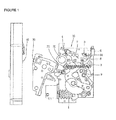
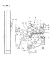
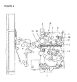
- FIGS. 1 , 2 , and 3 illustrate a broken (trip) state (or an open state), a charged state, a closed (conducted) state of the related art circuit breaker.
- a user may press an OFF button 6 to manually perform a breaking operation, or when a fault current is detected, a circuit is automatically broken (a trip operation) to change the circuit breaker into a broken state.
- an overcurrent trip relay installed outside an opening and closing mechanism 10 detects a fault current and transmits a trip control signal to an actuator, and the OFF shaft 4 is rotated in a clockwise direction by the actuator to start a breaking operation.
- a trip latch 7 is rotated in a clockwise direction so as to be released from a restrained state with respect to a main link 9 (or the trip latch 7 is rotated in a clockwise direction so as to be unlocked from the main link 9), and a breaking spring 2, which has been stretched in the closed state to charge elastic energy, discharges the elastic energy to pull a connection shaft 21 connected to one end portion of the breaking spring 2 to rotate it in a counterclockwise direction.
- the opening and closing shaft 20 is also rotated in the counterclockwise direction and the connection link is moved to the right in FIG. 3 to pull a movable contactor 30 to the right, and the movable contactor 30 is separated from the fixed contactor 40, thus completing a manual breaking operation or automatic trip operation to electrically break the circuit.
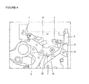
- FIGS. 4 and 5 are detailed views illustrating an operational relationship among the OFF shaft 4, the trip latch 7, and the main link 7 within the opening and closing mechanism 10 of the related art circuit breaker.
- the user may press the OFF button 6 to manually break the circuit breaker, or in case of a trip operation of the circuit breaker by an automatic trip executed when a fault current occurs, the OFF shaft 4 disposed on an upper portion of the opening and closing mechanism 10 is rotated in the clockwise direction.
- the trip latch 7 In the closed state, the trip latch 7 receiving a contact load (applied by the main link 9) in a contact portion 97 of the main link 9 and a trip latch roller 73 is rotated in the clockwise direction so as to be released (or unlocked) from the main link 9, and the contact load maintained in the contact portion of the main link 9 and the trip latch roller 73 in the closed state is changed into an open load, and as the open load is applied to the trip latch roller 73, a trip operation is substantially performed.
- circuit breaker that may reliably be changed into a broken state to cut off an electrical connection in the occurrence of an abnormal state in which the circuit breaker is not tripped in a manual manner or an auto-trip manner is required.
- An aspect of the present invention provides a circuit breaker having a mechanical trip mechanism for allowing for an emergency manual trip operation in an abnormal state in which the circuit breaker is not tripped in a manual manner or auto-trip manner.
- Another aspect of the present invention provides a
- a circuit breaker including: a fixed contactor connected to a circuit; a movable contactor movable to a closed state in which the movable contactor is in contact with the fixed contactor and a broken state in which the movable contactor is separated from the fixed contactor, an opening and closing mechanism configured to convert a rotational motion of a plurality of links and a rotational shaft to enable the movable contactor to be brought into contact with the fixed contactor or separated therefrom; a trip latch locked to or unlocked from a main link provided in the opening and closing mechanism; and an OFF button configured to rotate the trip latch to unlock the trip latch from the main link when manually pressed.
- mechanical trip mechanism when an auto-trip operation is not possibly performed in an abnormal state, mechanical trip mechanism performs an emergency manual trip operation to reliably change the circuit breaker into a broken state. Also, a condition in which the circuit breaker is not changed into a broken state by a manual operation is basically prevented, thus obtaining stability and reliability.
- the circuit breaker includes an opening and closing mechanism 10 converting a rotational motion of a plurality of links and a rotational shaft to compress a closing spring 1 and generating driving force according to elastic restoring force of the closing spring 1, an opening and closing shaft 20 connected to an opening and closing mechanism and transmitting driving force generated by the opening and closing mechanism, a fixed contactor 40, a movable contactor 30 movable to a closed state in which the movable contactor 30 is in contact with the fixed contactor 40 and a broken state in which the movable contactor 30 is separated from the fixed contactor, an overcurrent trip relay (not shown) outputting a control signal to trip the opening and closing mechanism 10 when an abnormal current is generated, and an actuator (not shown) for tripping the opening and closing mechanism by a control signal from the overcurrent trip relay.
- the configuration of the circuit breaker is the same as that of the related art circuit breaker, so a detailed configuration and operation thereof will be omitted.
- FIGS. 6 and 7 are perspective views of an OFF button and a trip latch provided in the related art circuit breaker.
- a connection pin 71 in an assembly of a trip latch 7, two trip latches placed to be parallel in a length direction are coupled by a connection pin 71.
- a rotational shaft 72 of the tip latch is installed to penetrate the assembly of the trip lath 7, and a trip latch roller 73 is provided between the rotational shaft 72 and one connection pin 71.
- a reinforcing unit 62 is provided in a body frame 61 of an OFF button 6 on a rear surface of the OFF button 6.
- the OFF button is supported to be rotatable at a predetermined angle by a button support 64 installed to penetrate an opening 63 formed in the reinforcing unit 62.
- a contact load is applied to a contact portion 97 of the main link 9 and the trip latch roller 73, and a locked state of the main link 9 and the trip latch roller 73 is maintained.
- the trip latch roller 73 is released from a state of being locked to the main link 9, a contact load is changed into an open load, and the open load is applied to the trip latch roller 73 by the main link 9.
- the OFF shaft 4 in an upper portion of the opening and closing mechanism 10 is rotated in a clockwise direction according to a manual and auto-trip operation, and accordingly, the trip lath 7 is rotated in a clockwise direction based on the rotational shaft 72 of the trip latch 7, and thus, the trip latch roller 73 locked in the main link 9 is released.
- the trip latch 7 should be rotated in the clockwise direction based on the rotational shaft 72 of the trip latch 7 to release the trip latch roller 73 locked in the main link 9.
- the mechanical trip mechanism includes a lever member 65 formed in the OFF button 6 and a protrusion member 75 coupled to the trip latch 7.
- the lever member 65 and the protrusion member 75 are in a relationship of an operating unit and an operated unit that directly rotate the trip latch 7 in the clockwise direction when a user presses the OFF button 6 in order to change the circuit breaker into a broken state.
- the lever member 65 provided on a rear surface of the OFF button 6 is provided in the reinforcing unit 62 of the OFF button having an opening 63 through which a button support pin 64 is inserted.
- the leer member 65 is integrally formed with the OFF button 6.
- the lever member 65 integrally formed in a body frame 61 of the OFF button 6 is protruded to have a certain length such that it is parallel to a length direction of the trip latch 7.
- the lever member 65 has a rectangular parallelepiped shape overall, and a front end portion 66 of the lever member 65 has a curved surface.
- an ON button (not shown) and the OFF button 6 installed on a front portion of the circuit breaker and manually operated by the user are installed to be supported by a button support pin 64 penetrating the opening 63 of the OFF button 6.
- the OFF button is rotatable within a predetermined angle range based on the button support pin 64.
- the protrusion member 75 of the trip latch 7 is provided on one surface of the trip latch 7.
- the protrusion member 75 of the trip lath 7 is protruded to have a predetermined length toward the lever member 65 of the OFF button 6 along an axial line direction of the rotational shaft 72 of the trip latch 7.
- the protrusion member 75 is protruded to slightly exceed the lever member 65 of the OFF button in a state of being installed in the opening and closing mechanism.
- the front end portion 66 of the lever member 65 rotated together according to the rotation of the OFF button reliably pressurizes the side of the protrusion member 75.
- the protrusion member 75 may be integrally formed with the trip latch 7 or may be separately formed and coupled to the trip latch 7. When the protrusion member 75 is separately formed, the protrusion member 75 may be coupled to the trip latch 7 according to a certain method known in the art. For example, the protrusion member 75 may be coupled to the trip latch 7 according to a coupling method such as welding, caulking coupling, bolt fastening, or the like.
- an OFF button 6 according to a second embodiment of the present invention including a mechanical trip mechanism is illustrated.
- the lever member 65 is formed on the body frame 61 of a rear surface of the OFF button 6.
- the lever member 65 according to the second embodiment includes a first lever unit 65a and a second lever unit 65b.
- the first lever unit 65a extends to be parallel to a length direction of the trip latch 7, and the second lever unit 65b is protruded from an end portion of the first lever unit 54a toward the trip latch 7 such that it is parallel to the rotational shaft of the trip latch 7.
- the second lever unit 65b In order to allow the second lever unit 65b to rotate the trip latch 7 in a clockwise direction, the second lever unit 65b has a length sufficient to simultaneously press one edge portion 75 of the trip latch 7 or both edge portions of the trip latch 7 of the trip latch assembly. Also, in the second embodiment, preferably, the lever member 65 is integrally formed with the OFF button 6. However, the second lever unit 65b of the lever member 65 may be separately formed and coupled.
- the lever member 65 provided in the OFF button 6 and having the first lever unit 65a and the second lever unit 65b has both the functions of the mechanical trip mechanism of the lever member 65 provided in the OFF button 6 and the protrusion member 75 provided in the trip latch 7.
- the second lever unit 65b of the lever member 65 according to the second embodiment of the present invention corresponds to the protrusion member in the first embodiment as described above.
- the second lever 65b of the lever member 65 when the lever member 65 is rotated as the OFF button 6 is pressed, the second lever 65b of the lever member 65 directly presses the edge portion 74 of the trip latch 7 to rotate the trip latch 7 in a clockwise direction based on the rotational shaft 72 of the trip latch 7.
- FIGS. 11 and 12 are detailed views illustrating a trip operation of the circuit breaker by the OFF button 6 and the trip latch 7 having the mechanical trip mechanism according to an embodiment of the present invention, and the mechanical trip mechanism corresponds to the first embodiment including the lever member 65 of the OFF button and the protrusion member 75 of the trip latch 7.
- the OFF button 6 when the user manually presses the OFF button 6 provided on a front portion of the circuit breaker, the OFF button rotates based on the button support pin 64. At the same time, the lever member 65 of the OFF button is rotated. Thus, as shown in FIG. 11 , the front end portion 66 of the lever member is brought into a lateral surface of the protrusion member 75 provided in the trip latch 7 to pressurize the trip latch 7. Subsequently, in a continuous process, as shown in FIG. 12 , the lever member 65 continuously pressurizes the protrusion member 75 of the trip latch 7, and thus, the trip latch 7 is rotated in a clockwise direction.
- the trip latch roller 73 locked in the main link 9 is released, and a contact load maintained in the contact portion 97 of the main link 9 and the trip latch roller 73 in the closed state of the circuit breaker is changed into an open load and transmitted to the trip latch roller 73. Accordingly, the trip operation of the circuit breaker is certainly, reliably executed.
- the second lever unit 65b of the lever member 65 provided in the OFF button 6 directly pressurizes the edge portion 74 of the trip latch 7, and thus, the trip latch 7 is rotated in the clockwise direction.
- the trip latch roller 73 locked in the main link 9 is released, thus executing a trip operation of the circuit beaker.
- the trip latch 7 can be directly rotated in the clockwise direction in association with an operation of the OFF button 6 to release the trip latch roller 73 locked in the main link 9.
- the circuit breaker can be change into a broken state through the emergency manual trip operation.
- a situation in which the circuit breaker is not changed into a broken state through a manual operation is fundamentally prevented.
Landscapes
- Breakers (AREA)
- Driving Mechanisms And Operating Circuits Of Arc-Extinguishing High-Tension Switches (AREA)
Abstract
Description
- The present invention relates to a circuit breaker and, more particularly, to a circuit breaker having a mechanical trip mechanism enabling a circuit breaker to perform an emergency manual trip operation.
- In general, a circuit breaker is a device for selectively turning on or off or breaking a line between a power side and a load side in the occurrence of an overload, a short-circuit fault, an electric leakage, or an electric shock.
-
FIGS. 1 ,2 , and3 illustrate a broken (trip) state (or an open state), a charged state, a closed (conducted) state of the related art circuit breaker. - In the related art circuit breaker, a user may press an
OFF button 6 to manually perform a breaking operation, or when a fault current is detected, a circuit is automatically broken (a trip operation) to change the circuit breaker into a broken state. - In the case of the manual breaking operation, as illustrated in
FIG. 3 , when the user presses theOFF button 6 in a closed state, an OFF plate (not shown) is horizontally moved to the left inFIG. 3 to rotate anOFF shaft 4 in a clockwise direction to start a breaking operation of the circuit breaker. - In case of an automatic trip for interrupting a fault current in a circuit, an overcurrent trip relay installed outside an opening and
closing mechanism 10 detects a fault current and transmits a trip control signal to an actuator, and theOFF shaft 4 is rotated in a clockwise direction by the actuator to start a breaking operation. - No matter whether it is manual or automatic trip, when the
OFF shaft 4 is rotated in the clockwise direction, atrip latch 7 is rotated in a clockwise direction so as to be released from a restrained state with respect to a main link 9 (or thetrip latch 7 is rotated in a clockwise direction so as to be unlocked from the main link 9), and a breakingspring 2, which has been stretched in the closed state to charge elastic energy, discharges the elastic energy to pull aconnection shaft 21 connected to one end portion of the breakingspring 2 to rotate it in a counterclockwise direction. Accordingly, the opening and closingshaft 20 is also rotated in the counterclockwise direction and the connection link is moved to the right inFIG. 3 to pull amovable contactor 30 to the right, and themovable contactor 30 is separated from thefixed contactor 40, thus completing a manual breaking operation or automatic trip operation to electrically break the circuit. - In relation to the trip operation,
FIGS. 4 and5 are detailed views illustrating an operational relationship among theOFF shaft 4, thetrip latch 7, and themain link 7 within the opening andclosing mechanism 10 of the related art circuit breaker. In case of a circuit breaker that normally operates, the user may press theOFF button 6 to manually break the circuit breaker, or in case of a trip operation of the circuit breaker by an automatic trip executed when a fault current occurs, theOFF shaft 4 disposed on an upper portion of the opening andclosing mechanism 10 is rotated in the clockwise direction. In the closed state, thetrip latch 7 receiving a contact load (applied by the main link 9) in acontact portion 97 of themain link 9 and atrip latch roller 73 is rotated in the clockwise direction so as to be released (or unlocked) from themain link 9, and the contact load maintained in the contact portion of themain link 9 and thetrip latch roller 73 in the closed state is changed into an open load, and as the open load is applied to thetrip latch roller 73, a trip operation is substantially performed. - However, although the user presses the
OFF button 6 so theOFF shaft 4 is rotated, if thetrip latch 7 is not rotated in the clockwise direction and is not released from themain link 9, a trip operation of the circuit breaker is not actually performed, so a fault current cannot be interrupted. - Similarly, in the occurrence of an abnormal current, although the
OFF shaft 4 is operated according to an automatic trip operation, if thetrip latch 7 is not rotated in the clockwise direction due to several abnormal factors, thetrip latch 7 is not released from themain link 9, resulting in failure of interrupting the fault current. - Thus, a circuit breaker that may reliably be changed into a broken state to cut off an electrical connection in the occurrence of an abnormal state in which the circuit breaker is not tripped in a manual manner or an auto-trip manner is required.
- An aspect of the present invention provides a circuit breaker having a mechanical trip mechanism for allowing for an emergency manual trip operation in an abnormal state in which the circuit breaker is not tripped in a manual manner or auto-trip manner.
- Another aspect of the present invention provides a
- According to an aspect of the present invention, there is provided a circuit breaker including: a fixed contactor connected to a circuit; a movable contactor movable to a closed state in which the movable contactor is in contact with the fixed contactor and a broken state in which the movable contactor is separated from the fixed contactor, an opening and closing mechanism configured to convert a rotational motion of a plurality of links and a rotational shaft to enable the movable contactor to be brought into contact with the fixed contactor or separated therefrom; a trip latch locked to or unlocked from a main link provided in the opening and closing mechanism; and an OFF button configured to rotate the trip latch to unlock the trip latch from the main link when manually pressed.
- According to an embodiment of the present invention, when an auto-trip operation is not possibly performed in an abnormal state, mechanical trip mechanism performs an emergency manual trip operation to reliably change the circuit breaker into a broken state. Also, a condition in which the circuit breaker is not changed into a broken state by a manual operation is basically prevented, thus obtaining stability and reliability.
- The foregoing and other objects, features, aspects and advantages of the present invention will become more apparent from the following detailed description of the present invention when taken in conjunction with the accompanying drawings.
-
-
FIG. 1 is a side view illustrating a broken state of the related art circuit breaker; -
FIG. 2 is a side view illustrating a charged state of the related art circuit breaker; -
FIG. 3 is a side view illustrating a closed state of the related art circuit breaker; -
FIG. 4 is a detailed view of a trip operation by an OFF shaft and a trip latch in the related art circuit breaker; -
FIG. 5 is a detailed view of a trip operation by a trip latch and a main link in the related art circuit breaker; -
FIG. 6 is a perspective view of a trip latch assembly installed in an opening and closing mechanism of the related art circuit breaker; -
FIG. 7 is a perspective view of an OFF button installed in the opening and closing mechanism of the related art circuit breaker; -
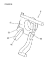
FIG. 8 is a perspective view of an OFF button of a circuit breaker according to a first embodiment of the present invention; -
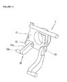
FIG. 9 is a perspective view of a trip latch assembly of the circuit breaker according to the first embodiment of the present invention; -
FIG. 10 is a perspective view of an OFF button of a circuit breaker according to a second embodiment of the present invention; and -
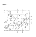
FIGS. 11 and12 are detailed views of a trip operation by the OFF button and the trip latch assembly of the circuit breaker according to the first embodiment of the present invention. - Hereinafter, a mechanical trip mechanism of a circuit breaker according to an embodiment of the present invention will be described in detail with reference to the accompanying drawings.
- The circuit breaker includes an opening and
closing mechanism 10 converting a rotational motion of a plurality of links and a rotational shaft to compress aclosing spring 1 and generating driving force according to elastic restoring force of theclosing spring 1, an opening andclosing shaft 20 connected to an opening and closing mechanism and transmitting driving force generated by the opening and closing mechanism, afixed contactor 40, amovable contactor 30 movable to a closed state in which themovable contactor 30 is in contact with thefixed contactor 40 and a broken state in which themovable contactor 30 is separated from the fixed contactor, an overcurrent trip relay (not shown) outputting a control signal to trip the opening andclosing mechanism 10 when an abnormal current is generated, and an actuator (not shown) for tripping the opening and closing mechanism by a control signal from the overcurrent trip relay. The configuration of the circuit breaker is the same as that of the related art circuit breaker, so a detailed configuration and operation thereof will be omitted. -
FIGS. 6 and7 are perspective views of an OFF button and a trip latch provided in the related art circuit breaker. As illustrated inFIG. 6 , in an assembly of atrip latch 7, two trip latches placed to be parallel in a length direction are coupled by aconnection pin 71. Arotational shaft 72 of the tip latch is installed to penetrate the assembly of thetrip lath 7, and atrip latch roller 73 is provided between therotational shaft 72 and oneconnection pin 71. As can be seen inFIG. 7 , a reinforcingunit 62 is provided in abody frame 61 of anOFF button 6 on a rear surface of theOFF button 6. The OFF button is supported to be rotatable at a predetermined angle by abutton support 64 installed to penetrate an opening 63 formed in thereinforcing unit 62. - In a closed state of the circuit breaker, the
main link 9 and thetrip latch 7 are locked, a contact load is applied to acontact portion 97 of themain link 9 and thetrip latch roller 73, and a locked state of themain link 9 and thetrip latch roller 73 is maintained. When the circuit breaker is changed from a closed state to a broken state, thetrip latch roller 73 is released from a state of being locked to themain link 9, a contact load is changed into an open load, and the open load is applied to thetrip latch roller 73 by themain link 9. - When the circuit breaker normally operates, the
OFF shaft 4 in an upper portion of the opening andclosing mechanism 10 is rotated in a clockwise direction according to a manual and auto-trip operation, and accordingly, thetrip lath 7 is rotated in a clockwise direction based on therotational shaft 72 of thetrip latch 7, and thus, thetrip latch roller 73 locked in themain link 9 is released. Thus, in order for the circuit breaker to be actually changed from the closed state to the broken state, thetrip latch 7 should be rotated in the clockwise direction based on therotational shaft 72 of thetrip latch 7 to release thetrip latch roller 73 locked in themain link 9. - Hereinafter, the mechanical trip mechanism of the circuit breaker according to an embodiment of the present invention will be described in detail.
- First, a configuration of the mechanical trip mechanism of the circuit breaker according to an embodiment of the present invention will be described.
- In
FIGS. 8 and9 , theOFF button 6 and thetrip lath 7 according to a first embodiment of the present invention including the mechanical trip mechanism are illustrated. The mechanical trip mechanism includes alever member 65 formed in theOFF button 6 and aprotrusion member 75 coupled to thetrip latch 7. Thelever member 65 and theprotrusion member 75 are in a relationship of an operating unit and an operated unit that directly rotate thetrip latch 7 in the clockwise direction when a user presses theOFF button 6 in order to change the circuit breaker into a broken state. - As illustrated in
FIG. 9 , thelever member 65 provided on a rear surface of theOFF button 6 is provided in the reinforcingunit 62 of the OFF button having anopening 63 through which abutton support pin 64 is inserted. Preferably, theleer member 65 is integrally formed with theOFF button 6. Thelever member 65 integrally formed in abody frame 61 of theOFF button 6 is protruded to have a certain length such that it is parallel to a length direction of thetrip latch 7. Thelever member 65 has a rectangular parallelepiped shape overall, and afront end portion 66 of thelever member 65 has a curved surface. In general, an ON button (not shown) and theOFF button 6 installed on a front portion of the circuit breaker and manually operated by the user are installed to be supported by abutton support pin 64 penetrating theopening 63 of theOFF button 6. Thus, when the user presses the button, the OFF button is rotatable within a predetermined angle range based on thebutton support pin 64. - As illustrated in
FIG. 8 , theprotrusion member 75 of thetrip latch 7 is provided on one surface of thetrip latch 7. Theprotrusion member 75 of thetrip lath 7 is protruded to have a predetermined length toward thelever member 65 of theOFF button 6 along an axial line direction of therotational shaft 72 of thetrip latch 7. As for the length of theprotrusion member 75, theprotrusion member 75 is protruded to slightly exceed thelever member 65 of the OFF button in a state of being installed in the opening and closing mechanism. Thus, when the OFF button is rotated based on thebutton support pin 64 as the user presses theOFF button 6, thefront end portion 66 of thelever member 65 rotated together according to the rotation of the OFF button reliably pressurizes the side of theprotrusion member 75. - The
protrusion member 75 may be integrally formed with thetrip latch 7 or may be separately formed and coupled to thetrip latch 7. When theprotrusion member 75 is separately formed, theprotrusion member 75 may be coupled to thetrip latch 7 according to a certain method known in the art. For example, theprotrusion member 75 may be coupled to thetrip latch 7 according to a coupling method such as welding, caulking coupling, bolt fastening, or the like. - Referring to
FIG. 10 , anOFF button 6 according to a second embodiment of the present invention including a mechanical trip mechanism is illustrated. In the second embodiment, thelever member 65 is formed on thebody frame 61 of a rear surface of theOFF button 6. Unlike the first embodiment as described above, thelever member 65 according to the second embodiment includes afirst lever unit 65a and asecond lever unit 65b. Thefirst lever unit 65a extends to be parallel to a length direction of thetrip latch 7, and thesecond lever unit 65b is protruded from an end portion of the first lever unit 54a toward thetrip latch 7 such that it is parallel to the rotational shaft of thetrip latch 7. In order to allow thesecond lever unit 65b to rotate thetrip latch 7 in a clockwise direction, thesecond lever unit 65b has a length sufficient to simultaneously press oneedge portion 75 of thetrip latch 7 or both edge portions of thetrip latch 7 of the trip latch assembly. Also, in the second embodiment, preferably, thelever member 65 is integrally formed with theOFF button 6. However, thesecond lever unit 65b of thelever member 65 may be separately formed and coupled. - In the case of the second embodiment illustrated in
FIG. 10 , thelever member 65 provided in theOFF button 6 and having thefirst lever unit 65a and thesecond lever unit 65b has both the functions of the mechanical trip mechanism of thelever member 65 provided in theOFF button 6 and theprotrusion member 75 provided in thetrip latch 7. Namely, thesecond lever unit 65b of thelever member 65 according to the second embodiment of the present invention corresponds to the protrusion member in the first embodiment as described above. Thus, in the second embodiment, when thelever member 65 is rotated as theOFF button 6 is pressed, thesecond lever 65b of thelever member 65 directly presses theedge portion 74 of thetrip latch 7 to rotate thetrip latch 7 in a clockwise direction based on therotational shaft 72 of thetrip latch 7. - Hereinafter, an operation of the mechanical trip mechanism in the circuit breaker according to an embodiment of the present invention will be described.
-
FIGS. 11 and12 are detailed views illustrating a trip operation of the circuit breaker by theOFF button 6 and thetrip latch 7 having the mechanical trip mechanism according to an embodiment of the present invention, and the mechanical trip mechanism corresponds to the first embodiment including thelever member 65 of the OFF button and theprotrusion member 75 of thetrip latch 7. - In the circuit breaker according to an embodiment of the present invention, when the user manually presses the
OFF button 6 provided on a front portion of the circuit breaker, the OFF button rotates based on thebutton support pin 64. At the same time, thelever member 65 of the OFF button is rotated. Thus, as shown inFIG. 11 , thefront end portion 66 of the lever member is brought into a lateral surface of theprotrusion member 75 provided in thetrip latch 7 to pressurize thetrip latch 7. Subsequently, in a continuous process, as shown inFIG. 12 , thelever member 65 continuously pressurizes theprotrusion member 75 of thetrip latch 7, and thus, thetrip latch 7 is rotated in a clockwise direction. Accordingly, thetrip latch roller 73 locked in themain link 9 is released, and a contact load maintained in thecontact portion 97 of themain link 9 and thetrip latch roller 73 in the closed state of the circuit breaker is changed into an open load and transmitted to thetrip latch roller 73. Accordingly, the trip operation of the circuit breaker is certainly, reliably executed. - Also, in the second embodiment, similarly, when the
OFF button 6 is operated manually, thesecond lever unit 65b of thelever member 65 provided in theOFF button 6 directly pressurizes theedge portion 74 of thetrip latch 7, and thus, thetrip latch 7 is rotated in the clockwise direction. As thetrip latch 7 is rotated in the clockwise direction, thetrip latch roller 73 locked in themain link 9 is released, thus executing a trip operation of the circuit beaker. - As described above, in the circuit breaker according to an embodiment of the present invention, since the
OFF button 6 includes the mechanical trip mechanism as an emergency manual trip means, thetrip latch 7 can be directly rotated in the clockwise direction in association with an operation of theOFF button 6 to release thetrip latch roller 73 locked in themain link 9. Thus, even when an auto-trip operation is not possibly performed in an abnormal situation, the circuit breaker can be change into a broken state through the emergency manual trip operation. In addition, a situation in which the circuit breaker is not changed into a broken state through a manual operation is fundamentally prevented. - As the present invention may be embodied in several forms without departing from the characteristics thereof, it should also be understood that the above-described embodiments are not limited by any of the details of the foregoing description, unless otherwise specified, but rather should be construed broadly within its scope as defined in the appended claims, and therefore all changes and modifications that fall within the metes and bounds of the claims, or equivalents of such metes and bounds are therefore intended to be embraced by the appended claims.
Claims (6)
- A circuit breaker comprising:a fixed contactor connected to a circuit;a movable contactor movable to a closed state in which the movable contactor is in contact with the fixed contactor and a broken state in which the movable contactor is separated from the fixed contactor;an opening and closing mechanism configured to convert a rotational motion of a plurality of links and a rotational shaft to enable the movable contactor to be brought into contact with the fixed contactor or separated therefrom;a trip latch locked to or unlocked from a main link provided in the opening and closing mechanism; andan OFF button configured to rotate the trip latch to unlock the trip latch from the main link when manually pressed.
- The circuit breaker of claim 1, wherein the OFF button includes a lever member configured to rotate the trip latch.
- The circuit breaker of claim 2, wherein the trip latch includes a protrusion member pressed by the lever member.
- The circuit breaker of claim 2, wherein the lever member includes a first lever unit extending to be parallel to a length direction of the trip latch and a second lever unit extending to be parallel to a rotational axial line of the trip latch.
- The circuit breaker of claim 4, wherein the second lever unit of the lever member extends in the axial line direction of a rotational shaft of the trip latch from an end portion of the first lever unit.
- The circuit breaker of claim 4 or 5, wherein the second lever unit presses an edge portion of the trip latch to rotate the trip latch.
Applications Claiming Priority (1)
| Application Number | Priority Date | Filing Date | Title |
|---|---|---|---|
| KR20110147818A KR101278501B1 (en) | 2011-12-30 | 2011-12-30 | Circuit breaker provided with a mechanical trip mechanism |
Publications (2)
| Publication Number | Publication Date |
|---|---|
| EP2610882A1 true EP2610882A1 (en) | 2013-07-03 |
| EP2610882B1 EP2610882B1 (en) | 2015-09-30 |
Family
ID=47458768
Family Applications (1)
| Application Number | Title | Priority Date | Filing Date |
|---|---|---|---|
| EP12199560.9A Not-in-force EP2610882B1 (en) | 2011-12-30 | 2012-12-28 | Circuit breaker provided with mechanical trip mechanism |
Country Status (7)
| Country | Link |
|---|---|
| US (1) | US8975546B2 (en) |
| EP (1) | EP2610882B1 (en) |
| JP (1) | JP5711205B2 (en) |
| KR (1) | KR101278501B1 (en) |
| CN (1) | CN103187212B (en) |
| BR (1) | BR102012033766A2 (en) |
| ES (1) | ES2556463T3 (en) |
Cited By (1)
| Publication number | Priority date | Publication date | Assignee | Title |
|---|---|---|---|---|
| EP3333865A4 (en) * | 2015-08-04 | 2019-03-27 | Zhejiang Chint Electrics Co., Ltd. | OPERATING MECHANISM OF ENERGY STORAGE OF CIRCUIT BREAKER |
Families Citing this family (8)
| Publication number | Priority date | Publication date | Assignee | Title |
|---|---|---|---|---|
| DE102014110757B4 (en) * | 2014-07-29 | 2016-12-29 | Eaton Industries Austria Gmbh | switchgear |
| CN104576239A (en) * | 2015-01-05 | 2015-04-29 | 无锡新宏泰电器科技股份有限公司 | Free tripping device for operating mechanism of air circuit breaker |
| KR101689531B1 (en) * | 2015-05-12 | 2016-12-27 | 현대중공업 주식회사 | Circuit breaker |
| CN106710982B (en) * | 2015-07-16 | 2018-09-21 | 上海良信电器股份有限公司 | The control mechanism of circuit breaker operation mechanism |
| KR101759601B1 (en) * | 2015-12-28 | 2017-07-31 | 엘에스산전 주식회사 | Delay time generation apparatus for air circuit breaker |
| KR101948723B1 (en) * | 2018-05-16 | 2019-02-15 | 엘에스산전 주식회사 | DC circuit breaker with manual trip mechanism |
| CN109727826B (en) | 2018-12-28 | 2024-08-13 | 浙江正泰电器股份有限公司 | Small-sized circuit breaker |
| FR3105565B1 (en) * | 2019-12-23 | 2022-01-14 | Schneider Electric Ind Sas | Electric current cut-off device |
Citations (2)
| Publication number | Priority date | Publication date | Assignee | Title |
|---|---|---|---|---|
| US5973278A (en) * | 1998-05-07 | 1999-10-26 | Eaton Corporation | Snap acting charge/discharge and open/closed indicators displaying states of electrical switching apparatus |
| EP2015336A1 (en) * | 2007-07-12 | 2009-01-14 | LS Industrial Systems Co., Ltd | Air circuit breaker with mechanical trip indicating mechanism |
Family Cites Families (11)
| Publication number | Priority date | Publication date | Assignee | Title |
|---|---|---|---|---|
| JPS60257014A (en) | 1984-06-01 | 1985-12-18 | 株式会社日立製作所 | Device for manufally closing and tripping breaker |
| JPH0869734A (en) | 1994-08-29 | 1996-03-12 | Mitsubishi Electric Corp | Breaker mechanical interlock device |
| JP3619948B2 (en) | 1997-07-15 | 2005-02-16 | 三菱電機株式会社 | Interlock device for electrical equipment |
| JP4186409B2 (en) * | 2000-10-30 | 2008-11-26 | 富士電機機器制御株式会社 | Circuit breaker |
| DE10320681B4 (en) * | 2003-04-30 | 2006-10-19 | Siemens Ag | Switch lock for latching a selector shaft and electrical switch with such a switch lock |
| KR100516944B1 (en) * | 2003-12-26 | 2005-09-23 | 엘에스산전 주식회사 | Interlocking structure of lead starting under voltage trip gear |
| KR100828931B1 (en) | 2006-01-20 | 2008-05-13 | 주식회사 제노프릭스 | Universal remote control system for multiple device control |
| KR100771918B1 (en) | 2006-10-17 | 2007-11-01 | 엘에스산전 주식회사 | Switchgear of the air circuit breaker |
| KR100882399B1 (en) * | 2007-08-20 | 2009-02-05 | 엘에스산전 주식회사 | Circuit breakers with automatic release link mechanisms and automatic release link mechanisms used therein |
| CN101599396B (en) | 2009-07-16 | 2011-06-15 | 浙江三蒙电气科技有限公司 | Circuit breaker |
| CN202058671U (en) * | 2011-05-27 | 2011-11-30 | 德力西电气(宁波)有限公司 | Spring-back resistant device for breaker |
-
2011
- 2011-12-30 KR KR20110147818A patent/KR101278501B1/en not_active Expired - Fee Related
-
2012
- 2012-12-26 US US13/727,328 patent/US8975546B2/en not_active Expired - Fee Related
- 2012-12-28 BR BRBR102012033766-5A patent/BR102012033766A2/en not_active Application Discontinuation
- 2012-12-28 CN CN201210598992.3A patent/CN103187212B/en not_active Expired - Fee Related
- 2012-12-28 JP JP2012288083A patent/JP5711205B2/en not_active Expired - Fee Related
- 2012-12-28 ES ES12199560.9T patent/ES2556463T3/en active Active
- 2012-12-28 EP EP12199560.9A patent/EP2610882B1/en not_active Not-in-force
Patent Citations (2)
| Publication number | Priority date | Publication date | Assignee | Title |
|---|---|---|---|---|
| US5973278A (en) * | 1998-05-07 | 1999-10-26 | Eaton Corporation | Snap acting charge/discharge and open/closed indicators displaying states of electrical switching apparatus |
| EP2015336A1 (en) * | 2007-07-12 | 2009-01-14 | LS Industrial Systems Co., Ltd | Air circuit breaker with mechanical trip indicating mechanism |
Cited By (2)
| Publication number | Priority date | Publication date | Assignee | Title |
|---|---|---|---|---|
| EP3333865A4 (en) * | 2015-08-04 | 2019-03-27 | Zhejiang Chint Electrics Co., Ltd. | OPERATING MECHANISM OF ENERGY STORAGE OF CIRCUIT BREAKER |
| US10643801B2 (en) | 2015-08-04 | 2020-05-05 | Zhejiang Chint Electrics Co., Ltd. | Circuit breaker energy storage operating mechanism |
Also Published As
| Publication number | Publication date |
|---|---|
| US8975546B2 (en) | 2015-03-10 |
| CN103187212A (en) | 2013-07-03 |
| ES2556463T3 (en) | 2016-01-18 |
| KR101278501B1 (en) | 2013-07-02 |
| BR102012033766A2 (en) | 2015-05-12 |
| JP2013140799A (en) | 2013-07-18 |
| JP5711205B2 (en) | 2015-04-30 |
| EP2610882B1 (en) | 2015-09-30 |
| US20130168213A1 (en) | 2013-07-04 |
| CN103187212B (en) | 2015-10-14 |
Similar Documents
| Publication | Publication Date | Title |
|---|---|---|
| EP2610882B1 (en) | Circuit breaker provided with mechanical trip mechanism | |
| EP2028671B1 (en) | Circuit breaker having automatic release linkage | |
| EP2028672B1 (en) | Circuit breaker having automatic release linkage | |
| RU2378730C1 (en) | Air circuit breaker with mechanical trip indicating mechanism | |
| EP2355121B1 (en) | Circuit breaker having trip cause indicating mechanism | |
| US7973622B2 (en) | Apparatus for auxiliary contact of circuit breaker | |
| JP5426516B2 (en) | Circuit breaker with instantaneous trip mechanism | |
| CN101369502A (en) | Electrical switching apparatus, and latch assembly and latch engagement control mechanism therefor | |
| EP2028670A2 (en) | Spring charging device of air circuit breaker | |
| EP3392898B1 (en) | Magnetic trip device of air circuit breaker | |
| CN116313667B (en) | Locking structure of breaker operating mechanism | |
| CN219759497U (en) | Locking structure of breaker operating mechanism | |
| CN102568948A (en) | Improved circuit breaker | |
| CN103295808B (en) | Switching device | |
| JP5217020B2 (en) | Circuit breaker switching mechanism | |
| JP7331803B2 (en) | circuit breaker | |
| KR101734229B1 (en) | Detecting unit for trip driving of circuit breaker | |
| CN221101987U (en) | Accessory device and operating mechanism on circuit breaker | |
| CN213483647U (en) | Spring-operated mechanism with loss-of-voltage and under-voltage trip protection | |
| JP2009259609A (en) | Switching mechanism for circuit breaker | |
| CN116864349A (en) | Auxiliary device for circuit breaker |
Legal Events
| Date | Code | Title | Description |
|---|---|---|---|
| PUAI | Public reference made under article 153(3) epc to a published international application that has entered the european phase |
Free format text: ORIGINAL CODE: 0009012 |
|
| AK | Designated contracting states |
Kind code of ref document: A1 Designated state(s): AL AT BE BG CH CY CZ DE DK EE ES FI FR GB GR HR HU IE IS IT LI LT LU LV MC MK MT NL NO PL PT RO RS SE SI SK SM TR |
|
| AX | Request for extension of the european patent |
Extension state: BA ME |
|
| RIN1 | Information on inventor provided before grant (corrected) |
Inventor name: YANG, HONG IK Inventor name: KIM, JONG DOO Inventor name: AHN, KIL YOUNG |
|
| 17P | Request for examination filed |
Effective date: 20140103 |
|
| RBV | Designated contracting states (corrected) |
Designated state(s): AL AT BE BG CH CY CZ DE DK EE ES FI FR GB GR HR HU IE IS IT LI LT LU LV MC MK MT NL NO PL PT RO RS SE SI SK SM TR |
|
| 17Q | First examination report despatched |
Effective date: 20140220 |
|
| GRAP | Despatch of communication of intention to grant a patent |
Free format text: ORIGINAL CODE: EPIDOSNIGR1 |
|
| INTG | Intention to grant announced |
Effective date: 20150520 |
|
| GRAS | Grant fee paid |
Free format text: ORIGINAL CODE: EPIDOSNIGR3 |
|
| GRAA | (expected) grant |
Free format text: ORIGINAL CODE: 0009210 |
|
| AK | Designated contracting states |
Kind code of ref document: B1 Designated state(s): AL AT BE BG CH CY CZ DE DK EE ES FI FR GB GR HR HU IE IS IT LI LT LU LV MC MK MT NL NO PL PT RO RS SE SI SK SM TR |
|
| REG | Reference to a national code |
Ref country code: CH Ref legal event code: EP Ref country code: GB Ref legal event code: FG4D |
|
| REG | Reference to a national code |
Ref country code: AT Ref legal event code: REF Ref document number: 752853 Country of ref document: AT Kind code of ref document: T Effective date: 20151015 |
|
| REG | Reference to a national code |
Ref country code: IE Ref legal event code: FG4D |
|
| REG | Reference to a national code |
Ref country code: DE Ref legal event code: R096 Ref document number: 602012011082 Country of ref document: DE |
|
| REG | Reference to a national code |
Ref country code: FR Ref legal event code: PLFP Year of fee payment: 4 |
|
| REG | Reference to a national code |
Ref country code: ES Ref legal event code: FG2A Ref document number: 2556463 Country of ref document: ES Kind code of ref document: T3 Effective date: 20160118 |
|
| PG25 | Lapsed in a contracting state [announced via postgrant information from national office to epo] |
Ref country code: NO Free format text: LAPSE BECAUSE OF FAILURE TO SUBMIT A TRANSLATION OF THE DESCRIPTION OR TO PAY THE FEE WITHIN THE PRESCRIBED TIME-LIMIT Effective date: 20151230 Ref country code: LV Free format text: LAPSE BECAUSE OF FAILURE TO SUBMIT A TRANSLATION OF THE DESCRIPTION OR TO PAY THE FEE WITHIN THE PRESCRIBED TIME-LIMIT Effective date: 20150930 Ref country code: LT Free format text: LAPSE BECAUSE OF FAILURE TO SUBMIT A TRANSLATION OF THE DESCRIPTION OR TO PAY THE FEE WITHIN THE PRESCRIBED TIME-LIMIT Effective date: 20150930 Ref country code: GR Free format text: LAPSE BECAUSE OF FAILURE TO SUBMIT A TRANSLATION OF THE DESCRIPTION OR TO PAY THE FEE WITHIN THE PRESCRIBED TIME-LIMIT Effective date: 20151231 Ref country code: FI Free format text: LAPSE BECAUSE OF FAILURE TO SUBMIT A TRANSLATION OF THE DESCRIPTION OR TO PAY THE FEE WITHIN THE PRESCRIBED TIME-LIMIT Effective date: 20150930 |
|
| REG | Reference to a national code |
Ref country code: NL Ref legal event code: MP Effective date: 20150930 |
|
| REG | Reference to a national code |
Ref country code: LT Ref legal event code: MG4D |
|
| REG | Reference to a national code |
Ref country code: AT Ref legal event code: MK05 Ref document number: 752853 Country of ref document: AT Kind code of ref document: T Effective date: 20150930 |
|
| PG25 | Lapsed in a contracting state [announced via postgrant information from national office to epo] |
Ref country code: RS Free format text: LAPSE BECAUSE OF FAILURE TO SUBMIT A TRANSLATION OF THE DESCRIPTION OR TO PAY THE FEE WITHIN THE PRESCRIBED TIME-LIMIT Effective date: 20150930 Ref country code: SE Free format text: LAPSE BECAUSE OF FAILURE TO SUBMIT A TRANSLATION OF THE DESCRIPTION OR TO PAY THE FEE WITHIN THE PRESCRIBED TIME-LIMIT Effective date: 20150930 Ref country code: HR Free format text: LAPSE BECAUSE OF FAILURE TO SUBMIT A TRANSLATION OF THE DESCRIPTION OR TO PAY THE FEE WITHIN THE PRESCRIBED TIME-LIMIT Effective date: 20150930 |
|
| PG25 | Lapsed in a contracting state [announced via postgrant information from national office to epo] |
Ref country code: SK Free format text: LAPSE BECAUSE OF FAILURE TO SUBMIT A TRANSLATION OF THE DESCRIPTION OR TO PAY THE FEE WITHIN THE PRESCRIBED TIME-LIMIT Effective date: 20150930 Ref country code: EE Free format text: LAPSE BECAUSE OF FAILURE TO SUBMIT A TRANSLATION OF THE DESCRIPTION OR TO PAY THE FEE WITHIN THE PRESCRIBED TIME-LIMIT Effective date: 20150930 Ref country code: NL Free format text: LAPSE BECAUSE OF FAILURE TO SUBMIT A TRANSLATION OF THE DESCRIPTION OR TO PAY THE FEE WITHIN THE PRESCRIBED TIME-LIMIT Effective date: 20150930 Ref country code: CZ Free format text: LAPSE BECAUSE OF FAILURE TO SUBMIT A TRANSLATION OF THE DESCRIPTION OR TO PAY THE FEE WITHIN THE PRESCRIBED TIME-LIMIT Effective date: 20150930 Ref country code: IS Free format text: LAPSE BECAUSE OF FAILURE TO SUBMIT A TRANSLATION OF THE DESCRIPTION OR TO PAY THE FEE WITHIN THE PRESCRIBED TIME-LIMIT Effective date: 20160130 |
|
| PG25 | Lapsed in a contracting state [announced via postgrant information from national office to epo] |
Ref country code: BE Free format text: LAPSE BECAUSE OF NON-PAYMENT OF DUE FEES Effective date: 20151231 Ref country code: RO Free format text: LAPSE BECAUSE OF FAILURE TO SUBMIT A TRANSLATION OF THE DESCRIPTION OR TO PAY THE FEE WITHIN THE PRESCRIBED TIME-LIMIT Effective date: 20150930 Ref country code: PT Free format text: LAPSE BECAUSE OF FAILURE TO SUBMIT A TRANSLATION OF THE DESCRIPTION OR TO PAY THE FEE WITHIN THE PRESCRIBED TIME-LIMIT Effective date: 20160201 Ref country code: PL Free format text: LAPSE BECAUSE OF FAILURE TO SUBMIT A TRANSLATION OF THE DESCRIPTION OR TO PAY THE FEE WITHIN THE PRESCRIBED TIME-LIMIT Effective date: 20150930 Ref country code: AT Free format text: LAPSE BECAUSE OF FAILURE TO SUBMIT A TRANSLATION OF THE DESCRIPTION OR TO PAY THE FEE WITHIN THE PRESCRIBED TIME-LIMIT Effective date: 20150930 |
|
| REG | Reference to a national code |
Ref country code: DE Ref legal event code: R097 Ref document number: 602012011082 Country of ref document: DE |
|
| PG25 | Lapsed in a contracting state [announced via postgrant information from national office to epo] |
Ref country code: MC Free format text: LAPSE BECAUSE OF FAILURE TO SUBMIT A TRANSLATION OF THE DESCRIPTION OR TO PAY THE FEE WITHIN THE PRESCRIBED TIME-LIMIT Effective date: 20150930 Ref country code: LU Free format text: LAPSE BECAUSE OF FAILURE TO SUBMIT A TRANSLATION OF THE DESCRIPTION OR TO PAY THE FEE WITHIN THE PRESCRIBED TIME-LIMIT Effective date: 20151228 |
|
| REG | Reference to a national code |
Ref country code: CH Ref legal event code: PL |
|
| PLBE | No opposition filed within time limit |
Free format text: ORIGINAL CODE: 0009261 |
|
| STAA | Information on the status of an ep patent application or granted ep patent |
Free format text: STATUS: NO OPPOSITION FILED WITHIN TIME LIMIT |
|
| PG25 | Lapsed in a contracting state [announced via postgrant information from national office to epo] |
Ref country code: DK Free format text: LAPSE BECAUSE OF FAILURE TO SUBMIT A TRANSLATION OF THE DESCRIPTION OR TO PAY THE FEE WITHIN THE PRESCRIBED TIME-LIMIT Effective date: 20150930 |
|
| 26N | No opposition filed |
Effective date: 20160701 |
|
| REG | Reference to a national code |
Ref country code: IE Ref legal event code: MM4A |
|
| REG | Reference to a national code |
Ref country code: FR Ref legal event code: PLFP Year of fee payment: 5 |
|
| PG25 | Lapsed in a contracting state [announced via postgrant information from national office to epo] |
Ref country code: IE Free format text: LAPSE BECAUSE OF NON-PAYMENT OF DUE FEES Effective date: 20151228 Ref country code: LI Free format text: LAPSE BECAUSE OF NON-PAYMENT OF DUE FEES Effective date: 20151231 Ref country code: CH Free format text: LAPSE BECAUSE OF NON-PAYMENT OF DUE FEES Effective date: 20151231 |
|
| PG25 | Lapsed in a contracting state [announced via postgrant information from national office to epo] |
Ref country code: SI Free format text: LAPSE BECAUSE OF FAILURE TO SUBMIT A TRANSLATION OF THE DESCRIPTION OR TO PAY THE FEE WITHIN THE PRESCRIBED TIME-LIMIT Effective date: 20150930 |
|
| PG25 | Lapsed in a contracting state [announced via postgrant information from national office to epo] |
Ref country code: BE Free format text: LAPSE BECAUSE OF FAILURE TO SUBMIT A TRANSLATION OF THE DESCRIPTION OR TO PAY THE FEE WITHIN THE PRESCRIBED TIME-LIMIT Effective date: 20150930 |
|
| PG25 | Lapsed in a contracting state [announced via postgrant information from national office to epo] |
Ref country code: SM Free format text: LAPSE BECAUSE OF FAILURE TO SUBMIT A TRANSLATION OF THE DESCRIPTION OR TO PAY THE FEE WITHIN THE PRESCRIBED TIME-LIMIT Effective date: 20150930 Ref country code: BG Free format text: LAPSE BECAUSE OF FAILURE TO SUBMIT A TRANSLATION OF THE DESCRIPTION OR TO PAY THE FEE WITHIN THE PRESCRIBED TIME-LIMIT Effective date: 20150930 Ref country code: HU Free format text: LAPSE BECAUSE OF FAILURE TO SUBMIT A TRANSLATION OF THE DESCRIPTION OR TO PAY THE FEE WITHIN THE PRESCRIBED TIME-LIMIT; INVALID AB INITIO Effective date: 20121228 |
|
| PG25 | Lapsed in a contracting state [announced via postgrant information from national office to epo] |
Ref country code: CY Free format text: LAPSE BECAUSE OF FAILURE TO SUBMIT A TRANSLATION OF THE DESCRIPTION OR TO PAY THE FEE WITHIN THE PRESCRIBED TIME-LIMIT Effective date: 20150930 |
|
| PG25 | Lapsed in a contracting state [announced via postgrant information from national office to epo] |
Ref country code: MT Free format text: LAPSE BECAUSE OF FAILURE TO SUBMIT A TRANSLATION OF THE DESCRIPTION OR TO PAY THE FEE WITHIN THE PRESCRIBED TIME-LIMIT Effective date: 20150930 |
|
| REG | Reference to a national code |
Ref country code: FR Ref legal event code: PLFP Year of fee payment: 6 |
|
| PG25 | Lapsed in a contracting state [announced via postgrant information from national office to epo] |
Ref country code: MK Free format text: LAPSE BECAUSE OF FAILURE TO SUBMIT A TRANSLATION OF THE DESCRIPTION OR TO PAY THE FEE WITHIN THE PRESCRIBED TIME-LIMIT Effective date: 20150930 Ref country code: TR Free format text: LAPSE BECAUSE OF FAILURE TO SUBMIT A TRANSLATION OF THE DESCRIPTION OR TO PAY THE FEE WITHIN THE PRESCRIBED TIME-LIMIT Effective date: 20150930 |
|
| REG | Reference to a national code |
Ref country code: FR Ref legal event code: PLFP Year of fee payment: 7 |
|
| PG25 | Lapsed in a contracting state [announced via postgrant information from national office to epo] |
Ref country code: AL Free format text: LAPSE BECAUSE OF FAILURE TO SUBMIT A TRANSLATION OF THE DESCRIPTION OR TO PAY THE FEE WITHIN THE PRESCRIBED TIME-LIMIT Effective date: 20150930 |
|
| PGFP | Annual fee paid to national office [announced via postgrant information from national office to epo] |
Ref country code: FR Payment date: 20180910 Year of fee payment: 7 |
|
| PGFP | Annual fee paid to national office [announced via postgrant information from national office to epo] |
Ref country code: DE Payment date: 20180905 Year of fee payment: 7 |
|
| PGFP | Annual fee paid to national office [announced via postgrant information from national office to epo] |
Ref country code: GB Payment date: 20181005 Year of fee payment: 7 Ref country code: IT Payment date: 20181210 Year of fee payment: 7 |
|
| PGFP | Annual fee paid to national office [announced via postgrant information from national office to epo] |
Ref country code: ES Payment date: 20190116 Year of fee payment: 7 |
|
| REG | Reference to a national code |
Ref country code: DE Ref legal event code: R119 Ref document number: 602012011082 Country of ref document: DE |
|
| GBPC | Gb: european patent ceased through non-payment of renewal fee |
Effective date: 20191228 |
|
| PG25 | Lapsed in a contracting state [announced via postgrant information from national office to epo] |
Ref country code: FR Free format text: LAPSE BECAUSE OF NON-PAYMENT OF DUE FEES Effective date: 20191231 Ref country code: IT Free format text: LAPSE BECAUSE OF NON-PAYMENT OF DUE FEES Effective date: 20191228 Ref country code: DE Free format text: LAPSE BECAUSE OF NON-PAYMENT OF DUE FEES Effective date: 20200701 Ref country code: GB Free format text: LAPSE BECAUSE OF NON-PAYMENT OF DUE FEES Effective date: 20191228 |
|
| REG | Reference to a national code |
Ref country code: ES Ref legal event code: FD2A Effective date: 20210524 |
|
| PG25 | Lapsed in a contracting state [announced via postgrant information from national office to epo] |
Ref country code: ES Free format text: LAPSE BECAUSE OF NON-PAYMENT OF DUE FEES Effective date: 20191229 |