EP2610816A1 - Vehicle unit with integrated antenna - Google Patents
Vehicle unit with integrated antenna Download PDFInfo
- Publication number
- EP2610816A1 EP2610816A1 EP11195926.8A EP11195926A EP2610816A1 EP 2610816 A1 EP2610816 A1 EP 2610816A1 EP 11195926 A EP11195926 A EP 11195926A EP 2610816 A1 EP2610816 A1 EP 2610816A1
- Authority
- EP
- European Patent Office
- Prior art keywords
- access panel
- antenna
- integrated antenna
- connection port
- vehicle
- Prior art date
- Legal status (The legal status is an assumption and is not a legal conclusion. Google has not performed a legal analysis and makes no representation as to the accuracy of the status listed.)
- Granted
Links
Images



Classifications
-
- G—PHYSICS
- G07—CHECKING-DEVICES
- G07C—TIME OR ATTENDANCE REGISTERS; REGISTERING OR INDICATING THE WORKING OF MACHINES; GENERATING RANDOM NUMBERS; VOTING OR LOTTERY APPARATUS; ARRANGEMENTS, SYSTEMS OR APPARATUS FOR CHECKING NOT PROVIDED FOR ELSEWHERE
- G07C5/00—Registering or indicating the working of vehicles
- G07C5/008—Registering or indicating the working of vehicles communicating information to a remotely located station
-
- G—PHYSICS
- G07—CHECKING-DEVICES
- G07B—TICKET-ISSUING APPARATUS; FARE-REGISTERING APPARATUS; FRANKING APPARATUS
- G07B13/00—Taximeters
- G07B13/02—Details; Accessories
-
- G—PHYSICS
- G07—CHECKING-DEVICES
- G07B—TICKET-ISSUING APPARATUS; FARE-REGISTERING APPARATUS; FRANKING APPARATUS
- G07B15/00—Arrangements or apparatus for collecting fares, tolls or entrance fees at one or more control points
-
- G—PHYSICS
- G07—CHECKING-DEVICES
- G07C—TIME OR ATTENDANCE REGISTERS; REGISTERING OR INDICATING THE WORKING OF MACHINES; GENERATING RANDOM NUMBERS; VOTING OR LOTTERY APPARATUS; ARRANGEMENTS, SYSTEMS OR APPARATUS FOR CHECKING NOT PROVIDED FOR ELSEWHERE
- G07C5/00—Registering or indicating the working of vehicles
Definitions
- the present invention relates generally to a communication arrangement in a vehicle unit and particularly to a vehicle unit having an integrated antenna.
- VU Vehicle Unit
- vehicle Unit shall mean a digital unit capable of gathering information relating to the vehicle.
- Examples of such information may be a geographical location, driving hours, distance traveled, start time, finish time, rest time, driver name, starting location and finishing location, exhaust measurements, fuel consumption, temperature data from vehicle or cargo sensors, opening and closing of cargo doors or operation of other vehicle systems, e.g. cranes and lifts etc.
- VU is a digital tachograph, capable of recording and digitally compiling and storing the vehicle data.
- the VU is normally located in the cabin of the vehicle, where the VU is arranged in the instrument board, so that the vehicle operator may operate the VU in adjacency to start or stop of a journey.
- the VU is in connectivity to one or more sensors, where the sensors are capable of measuring for instance the motion of the wheels or other parameters.
- the VU may be used by law enforcement to check whether or not the driver complies with the driving regulations.
- the VU is normally heavily regulated and must be certified to high standards regarding functionality, safety and security. It is therefore complicated to make changes and to add new functions. An extensive certification procedure can considerably contribute to a long time to market for changes and new functions.
- a hardware and software integrated data off-load function is desirable, such solution may not be economically feasible due to the above mentioned regulation and certification restrictions.
- the data stored within the VU is offloaded to an external device by connecting a cable to a connection port.
- the term "offloading data” shall be understood to be the function when the VU transfers the stored vehicle data to an external device.
- connection port is normally arranged, covered by an access panel, in a front end of the VU.
- the access panel is normally temporary removed to expose the connection port.
- the cable, connecting the external device to the connection port is removed and the access panel replaced.
- the access panel may be removed and an external "dongle" may be connected to the connection port.
- the dongle being powered by the connection port, may enable a wireless connection between the VU and an external device.
- connecting a dongle to the connection port also leaves the user with the access panel which is needed for other functionalities, such as printing.
- the dongle extends perpendicularly to the front end of the VU, the risk of physical damage, such as breakage in the connection of the connection port and the dongle, increases when the driver or a passenger moves around in the cabin of the vehicle.
- extending portions of e.g. a dongle increases the risk of physical trauma to the driver during for instance an accident.
- the dongle may also be in the way of other equipment that needs to be accessed or visible by the driver during operation of the vehicle. Since "nomadic equipment" such as a removable dongle sometimes has to be removed from the VU and inserted again such use causes irritation especially if the dongle is forgotten or lost as a result of this handling. Removable equipment with contact surfaces is also prone to cause loose connection over time which will reduce functionality.
- a Vehicle Unit having a front end which comprises a connection port and a space.
- the space is covered by an access panel which comprises an integrated antenna.
- the integrated antenna is arranged to be connected to a processing unit and the integrated antenna is arranged to be connected, via the processing unit, to the connection port.
- the integrated antenna is further arranged to wirelessly send signals to and receive signals from an external device.
- the integrated antenna and processing unit in the access panel enables retrofitting, i.e. the only part needed to be replaced is the access panel in order to enable wireless communication, compared to replacing the complete VU.
- Another advantage is that the access panel may be kept inserted and in a closed position enabling normal operation of the printer compared to removing the access panel to expose the connection port. Since the integrated antenna may enable wireless communication while the access panel is inserted, risk of breakage is reduced compared to if an antenna, or dongle, is connected directly to the communication port without any integration of the antenna.
- the access panel comprises a contact device connected to the integrated antenna.
- the contact device is arranged to connect the integrated antenna, via the processing unit, to the connection port.
- the access panel may be removable.
- the access panel may be arranged to be in at least an open position and a closed position.
- the contact device is adapted to be in contact with the connection port when the access panel is in a closed position and be disconnected from the connection port when the access panel is in an open position.
- the signals sent to the external device comprise signals may be related to vehicle data stored in the VU.
- the VU may be adapted to be in connection with a fleet management system via the external device, thereby enabling the fleet management system to request and/or receive vehicle data from the VU.
- the processing unit may be integrated with the access panel and may be arranged in series between the integrated antenna and the contact device.
- the antenna may be one of a, an Ultra-Wide band antenna, a Bluetooth antenna or an IEEE 802.11 antenna.
- the space may be adapted to comprise a removable printer module.
- the processing unit may be adapted to process a first communication protocol to a second communication protocol.
- the first protocol being applied in the wireless interface being formed between the external device and the integrated antenna
- the second communication protocol is a serial protocol for communication with the VU.
- the access panel comprises an external surface.
- the integrated antenna may be integrated into the access panel by moulding such that the antenna is arranged within the external surface of the access panel.
- the access panel comprises an external surface, wherein the integrated antenna is attached to the access panel.
- the vehicle unit is a digital tachograph.
- Fig. 1 shows a perspective view of a Vehicle Unit (VU) with a closed access panel
- Fig. 2 shows a perspective view of a Vehicle Unit (VU) with an open access panel
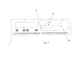
- Fig. 3 shows a front view of the Vehicle Unit (VU)
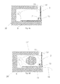
- Fig. 4a shows a side view of a removable printer unit, removed from the Vehicle Unit (VU)
- VU Vehicle Unit
- Fig. 4b shows a side view of a removable printer unit arranged inside the Vehicle Unit (VU)
- VU Vehicle Unit
- Fig. 4c shows a side view of a removable printer unit arranged inside the Vehicle Unit (VU)
- VU Vehicle Unit
- Fig. 4d shows a side view of a removable printer unit arranged inside the Vehicle Unit (VU)
- VU Vehicle Unit
- Fig. 5 illustrates a block chart of a signaling scenario involving a Vehicle Unit (VU) and a User Equipment
- Fig. 1 illustrates a perspective view of a Vehicle Unit ,VU, 1, such as a tachograph 1, for measuring, processing, storing or reporting collected vehicle data.
- the outer design and form factor of the VU 1 complies with standards in the field of tachographs such as e.g. ISO 7736.
- the front end 4 of the VU1 comprises an access panel 2 being in a closed position, i.e. wherein the access panel is closed, thereby covering a space 6 for housing a printer, preferably a removable printer module 8.
- the VU 1 further comprises a display 3, a first card tray 5 and a second card tray 5', and a first side end 4' to disclose the depth of the VU 1 in a direction perpendicular to the front side 4.
- Fig. 2 discloses the VU 1 of Fig. 1 wherein the access panel 2 has been brought to an open position, i.e. wherein the access panel 2 is open. Behind the access panel 2, the space 6 adapted to house the removable printer module 8 is disclosed. Preferably, the access panel 2 is pivotally arranged on the removable printer module 8 on the back side 2' of the access panel 2. On one side of the space 6 a connection port 7 has been arranged, wherein the connection port is accessible from the front side of the VU 1 and the ports connection pins extend in a direction normal to the plane of the front side. The connection port 7 is covered by the access panel 2 when the access panel 2 is in a closed position.
- connection port 7 is adapted for off-loading data stored in the VU 1 to an external device by connecting a cable between the connection port 7 and an external device.
- the connection port may be a serial connection port.
- the access panel 2 including the removable printer module 8 is removed entirely from the front end 4 of the VU 1 in order to expose the connection port 7. This may be done by a manual operation performed by for instance the driver of the vehicle, in a sequence of steps including first bringing the access panel 2 into an open position and thereafter pulling the access panel 2 in a direction normal to a plane of the access panel 2 and towards the driver.
- connection port 7 may be a serial data interface, i.e. a serial port.
- the connection port 7 may typically be arranged such that information stored or processed within the VU 1, can be offloaded to an external device.
- the usage and operation of serial ports exists in profusion in the prior art.
- Fig. 3 shows a front view of the VU 1, wherein the Figure shows a block chart of the components of the access panel 2 as well as the area covered by the access panel 2 when the access panel is in a closed position.
- the access panel 2 has been equipped with an integrated antenna 14. Integration of the integrated antenna 14 into the access panel 2 may be achieved by moulding the antenna into the material of the access panel 2, such as plastic, in a way that no portion of the antenna extends beyond the surface of the access panel 2, i.e. wherein the integrated antenna is arranged within the external surface of the access panel 2.
- the external surface of the access panel 2 means the outermost boundary of the access panel 2.
- Integration of the integrated antenna 14 into the material such as plastic may also comprise moulding the antenna 14 into the material such that a portion of the antenna 14 is arranged inside the external surface of the access panel 2 and a portion of the antenna 14 is arranged to protrude from the external surface of the access panel 2. Integration of the integrated antenna 14 into the material such as plastic of the access panel 2 may also comprise attaching an antenna onto and adjacent the surface of the access panel, preferably on a back side 2' of the access panel 2.
- the integrated antenna is preferably a short range antenna such as a Bluetooth antenna adapted to wirelessly send signals to, and receive signals from external devices located within or in close proximity of the vehicle.
- the integrated antenna 14 is further connected to a processing unit 9 for protocol processing or conversion wherein protocol processing or conversion comprises for instance protocol translation, tunneling, encapsulation, which will be described in further detail below in this description.
- the processing unit 9 and the integrated antenna 14 are further connectable to the connection port 7 via contact device 15.
- the processing unit 9 is connected in series between the integrated antenna 14 and the connection port 7.
- the processing unit 9 is integrated into the material of the access panel 2 together with the integrated antenna 14 during the moulding process of the access panel 2.
- the integration of the processing unit 9 may also mean that the processing unit 9 is attached onto and adjacent the surface of the access panel 2.
- Fig. 4a shows a side view of the removable printer unit 8 comprising the access panel 2 with the integrated antenna 14 and a contact device 15 for connecting the integrated antenna to the connection port 7, wherein the contact device 15 is arranged at the lowermost portion of the access panel 2, preferably on the back side 2' of the access panel 2.
- the Figure further shows the access panel in an open position wherein the removable printer unit 8 is removed from the VU 1. Further, a left side wall 11 and a lower surface portion 12 of the removable printer module 8 is disclosed in Fig. 4a .
- the access panel is pivotally arranged to the left side wall 11 and a right side wall (not shown) of the printer module 8, preferably by pins arranged on each side end of the back side 2' of the access panel 2 and adapted to engage two corresponding holes in the side walls enabling pivotal movement of the access panel 2 in relation to the printer module 8.
- a printer roller 13 is pivotally arranged on the back side 21 of the printer module 8 for feeding printer paper during print out of vehicle data.
- Fig. 4b shows the removable printer module 8 arranged in the space 6 with housing walls 20 being integrated in the VU 1 and encompassing the space 6, wherein the access panel 2 is in an open position.
- the contact device 15 In this position, wherein the access panel has been rotated to its outermost position in a counterclockwise direction, the contact device 15 is in a position such that there is a distance between the contact device 15 and the connection port 7, arranged in the VU 1 to the side of both the space 6 and the printer module 8, preferably in the housing wall 20. In this position, there is no connection between the integrated antenna 14 and the connection port 7.
- Fig. 4c shows the removable printer module 8 arranged in the space 6 of the VU 1, wherein the access panel is in a closed position. In this position, the access panel has been rotated to its outermost clockwise direction wherein the lowermost portion of the access panel 2 is adjacent the lower surface 12 of the printer module 8 and wherein the access panel 2 is essentially parallel to the plane of the front side 4.
- the connection port 7 has received the contact device 15 of the access panel 2, such that there is a connection there between, i.e. that there is a connection between the integrated antenna 14 and the connection port 7.
- Fig. 4d shows a side view similar to that of Fig. 4c , wherein a cylindrically shaped paper roll 17 is arranged between the side walls of the printer module 8. Paper from the paper roll 17 is guided from the paper roll 17 towards the back of the VU 1, above and around the printer roller 13, further extending below the lower portion of the printer module in a direction towards the front side 4 of the VU 1 to finally extend outside the front side 4 to be accessible by a driver printing out vehicle data.
- a printer of some kind e.g. a ink jet printer, or thermal printer, is arranged at the inner most portion of the space 6 (not shown), and prints vehicle data on the paper at a position essentially as the paper passes the printer roller 13.
- FIG. 5 a block chart illustrating a signaling scenario involving a VU 1, 32 and an external device, such as a User Equipment, UE, 33 is described.
- Fig. 5 shows a vehicle 30 having a VU 1, 32 arranged in the operating cabin of the vehicle 30.
- the VU 32 is in wireless communication connectivity with a UE 33.
- the VU 1, 32 can transmit data using high frequency radio communication. Although the distance of such radio communication is limited, 5 meters of signal reach will normally suffice to connect the VU 1, 32 and the UE 33.
- the VU 1, 32 comprises a Bluetooth antenna and processor, enabling a Personal Area Network, PAN, comprising the VU 1, 32 and one or more UEs 33.
- PAN Personal Area Network
- other wireless technologies such as Ultra-Wide Band (UWB) or Wireless Local Area Network LAN, Institute of Electrical and Electronics Engineers, IEEE, 802.11, are also possible for enabling a wireless communication between the VU 1, 32 and the UE 33.
- UWB Ultra-Wide Band
- LAN Institute of Electrical and Electronics Engineers, IEEE, 802.11
- the communication using wireless interface formed between the UE 33 and the integrated antenna of the VU 1, 32 is of a first communication protocol.
- the first communication protocol is defined in the prior art for WLAN, Bluetooth or any of the UWB implementations.
- the connection port may be of another interface type which requires protocol processing or conversion such as translation, tunneling or encapsulation from the first communication protocol into a second communication protocol, or vice versa, to enable the wireless communication.
- the communication port of the VU1, 32 as shown in Figs 2-4d , is a serial port having a serial communication physical interface which may require the processing unit, being connected to the integrated antenna, to process or convert, data to be sent, or which is received, to comply with the VU 1, 32 and the UE 33.
- the UE 33 may further be capable of receiving Global Positioning System, GPS, signals from one or more satellites 36.
- the UE 33 can thereby compile and structure information relating to the vehicle 30, provided by the VU 1, 32 using the wireless interface between the UE 33 and the VU 1, 32, based on the geographical position of the vehicle 30.
- the UE 33 may be capable of communicate using a Radio Access Network, RAN, comprising a Base Station 34.
- the BS 34 can then communicate, using a Wide Area Network, such as Internet or a private WAN, such as a corporate network, with a back end server 35, which may comprise a fleet management system.
- the UE 33 may also be adapted to communicate directly with a back end server 35 using a WAN or in certain situations a Wireless Local Area Network, WLAN. The latter may be preferable in a situation wherein the vehicle and the UE 33 is located or parked close to and using the WLAN of for instance a home office, goods terminal or at a customs station.
- WLAN Wireless Local Area Network
- the VU 1, 32 may provide information relating to the operation of the vehicle 30 to the UE 33 using the wireless interface between the VU 1, 32 and the UE 33. Then, the UE 33 may provide parts, or all, of the information relating to the operation of the vehicle to a back end server 35.
- the back end server 35 may then, based on the provided information, help the vehicle operator to make decisions for a more efficient transportation.
Landscapes
- Physics & Mathematics (AREA)
- General Physics & Mathematics (AREA)
- Traffic Control Systems (AREA)
- Fittings On The Vehicle Exterior For Carrying Loads, And Devices For Holding Or Mounting Articles (AREA)
Abstract
Description
- The present invention relates generally to a communication arrangement in a vehicle unit and particularly to a vehicle unit having an integrated antenna.
- Today, transportation by vehicle requires measurement of parameters and information relating to the driver activities. This is not exclusively done to satisfy regulations regarding road transportation, but also for fleet management to measure and increase performance and efficiency, as well as for the purpose of electronic road tolling, monitoring vehicle or engine performance parameters, monitoring data relevant for special transports e.g. dangerous goods, livestock or refrigerated food etc. Therefore, most vehicles, such as lorry trucks, carry a Vehicle Unit (VU) to measure, store and possible also report the collected data. In this document, the term "Vehicle Unit" shall mean a digital unit capable of gathering information relating to the vehicle. Examples of such information may be a geographical location, driving hours, distance traveled, start time, finish time, rest time, driver name, starting location and finishing location, exhaust measurements, fuel consumption, temperature data from vehicle or cargo sensors, opening and closing of cargo doors or operation of other vehicle systems, e.g. cranes and lifts etc. One example of a VU is a digital tachograph, capable of recording and digitally compiling and storing the vehicle data.
- The VU is normally located in the cabin of the vehicle, where the VU is arranged in the instrument board, so that the vehicle operator may operate the VU in adjacency to start or stop of a journey. In order to calculate and estimate the speed and the travel distance, or other parameters for instance as listed above, of the vehicle, the VU is in connectivity to one or more sensors, where the sensors are capable of measuring for instance the motion of the wheels or other parameters.
- The VU may be used by law enforcement to check whether or not the driver complies with the driving regulations. Hence, the VU is normally heavily regulated and must be certified to high standards regarding functionality, safety and security. It is therefore complicated to make changes and to add new functions. An extensive certification procedure can considerably contribute to a long time to market for changes and new functions. Although a hardware and software integrated data off-load function is desirable, such solution may not be economically feasible due to the above mentioned regulation and certification restrictions.
- According to the prior art solutions, the data stored within the VU is offloaded to an external device by connecting a cable to a connection port. The term "offloading data" shall be understood to be the function when the VU transfers the stored vehicle data to an external device.
- The connection port is normally arranged, covered by an access panel, in a front end of the VU. When offloading the vehicle data, then the access panel is normally temporary removed to expose the connection port. Once the offloading operation is completed, the cable, connecting the external device to the connection port, is removed and the access panel replaced. This solution may be sub-optimal if a continuous data feed between the VU and the external device is desired. The physical arrangement exposes the VU of increased risk of damage due to physical breakage as the driver is moving around in the cabin of the vehicle. Moreover, the access panel needs to be removed during the data offloading procedure and thereafter restored in place.
- According to another prior art solution, the access panel may be removed and an external "dongle" may be connected to the connection port. The dongle, being powered by the connection port, may enable a wireless connection between the VU and an external device. However, connecting a dongle to the connection port also leaves the user with the access panel which is needed for other functionalities, such as printing. Moreover, since the dongle extends perpendicularly to the front end of the VU, the risk of physical damage, such as breakage in the connection of the connection port and the dongle, increases when the driver or a passenger moves around in the cabin of the vehicle. Further, in addition to being unaesthetic in general, extending portions of e.g. a dongle increases the risk of physical trauma to the driver during for instance an accident. The dongle may also be in the way of other equipment that needs to be accessed or visible by the driver during operation of the vehicle. Since "nomadic equipment" such as a removable dongle sometimes has to be removed from the VU and inserted again such use causes irritation especially if the dongle is forgotten or lost as a result of this handling. Removable equipment with contact surfaces is also prone to cause loose connection over time which will reduce functionality.
- The current prior art solutions for achieving connectivity between the VU and an external device all have significant drawbacks. As previously discussed, add-on hardware increase the VU's exposure for physical trauma when the vehicle operator is moving inside the cabin.
- It is an object of the invention to address at least some of the limitations, problems and issues outlined above. It is also an object to provide a solution for enabling wireless communication between a Vehicle Unit, VU, and an external device. It may be possible to achieve these objects and others by using an arrangement as defined in the attached independent claims.
- According to one aspect, a Vehicle Unit, VU, having a front end which comprises a connection port and a space. The space is covered by an access panel which comprises an integrated antenna. The integrated antenna is arranged to be connected to a processing unit and the integrated antenna is arranged to be connected, via the processing unit, to the connection port. The integrated antenna is further arranged to wirelessly send signals to and receive signals from an external device.
- Having the integrated antenna and processing unit in the access panel enables retrofitting, i.e. the only part needed to be replaced is the access panel in order to enable wireless communication, compared to replacing the complete VU. Another advantage is that the access panel may be kept inserted and in a closed position enabling normal operation of the printer compared to removing the access panel to expose the connection port. Since the integrated antenna may enable wireless communication while the access panel is inserted, risk of breakage is reduced compared to if an antenna, or dongle, is connected directly to the communication port without any integration of the antenna.
- The above arrangements may be configured and implemented according to different embodiments. In one example embodiment, the access panel comprises a contact device connected to the integrated antenna. The contact device is arranged to connect the integrated antenna, via the processing unit, to the connection port. According to another embodiment, the access panel may be removable.
- According to another possible embodiment, the access panel may be arranged to be in at least an open position and a closed position. The contact device is adapted to be in contact with the connection port when the access panel is in a closed position and be disconnected from the connection port when the access panel is in an open position.
- According to one possible embodiment, the signals sent to the external device comprise signals may be related to vehicle data stored in the VU.
- According to another embodiment, the VU may be adapted to be in connection with a fleet management system via the external device, thereby enabling the fleet management system to request and/or receive vehicle data from the VU.
- According to another embodiment, the processing unit may be integrated with the access panel and may be arranged in series between the integrated antenna and the contact device.
- According to another possible embodiment, the antenna may be one of a, an Ultra-Wide band antenna, a Bluetooth antenna or an IEEE 802.11 antenna.
- According to another possible embodiment the space may be adapted to comprise a removable printer module.
- According to one possible embodiment, the processing unit may be adapted to process a first communication protocol to a second communication protocol. The first protocol being applied in the wireless interface being formed between the external device and the integrated antenna, and the second communication protocol is a serial protocol for communication with the VU.
- According to one possible embodiment, the access panel comprises an external surface. The integrated antenna may be integrated into the access panel by moulding such that the antenna is arranged within the external surface of the access panel.
- According to one possible embodiment, the access panel comprises an external surface, wherein the integrated antenna is attached to the access panel.
- According to one possible embodiment, the vehicle unit is a digital tachograph.
- Further possible features and benefits of this solution will become apparent from the detailed description below.
- The invention is now described, by way of example, with reference to the accompanying drawings, in which:
-
Fig. 1 shows a perspective view of a Vehicle Unit (VU) with a closed access panel -
Fig. 2 shows a perspective view of a Vehicle Unit (VU) with an open access panel -
Fig. 3 shows a front view of the Vehicle Unit (VU) -
Fig. 4a shows a side view of a removable printer unit, removed from the Vehicle Unit (VU) -
Fig. 4b shows a side view of a removable printer unit arranged inside the Vehicle Unit (VU) -
Fig. 4c shows a side view of a removable printer unit arranged inside the Vehicle Unit (VU) -
Fig. 4d shows a side view of a removable printer unit arranged inside the Vehicle Unit (VU) -
Fig. 5 illustrates a block chart of a signaling scenario involving a Vehicle Unit (VU) and a User Equipment - In the following, a detailed description of the invention will be given:
-
Fig. 1 illustrates a perspective view of a Vehicle Unit ,VU, 1, such as atachograph 1, for measuring, processing, storing or reporting collected vehicle data. The outer design and form factor of theVU 1 complies with standards in the field of tachographs such as e.g. ISO 7736. Thefront end 4 of the VU1 comprises anaccess panel 2 being in a closed position, i.e. wherein the access panel is closed, thereby covering aspace 6 for housing a printer, preferably aremovable printer module 8. TheVU 1 further comprises adisplay 3, afirst card tray 5 and a second card tray 5', and a first side end 4' to disclose the depth of theVU 1 in a direction perpendicular to thefront side 4. -
Fig. 2 discloses theVU 1 ofFig. 1 wherein theaccess panel 2 has been brought to an open position, i.e. wherein theaccess panel 2 is open. Behind theaccess panel 2, thespace 6 adapted to house theremovable printer module 8 is disclosed. Preferably, theaccess panel 2 is pivotally arranged on theremovable printer module 8 on the back side 2' of theaccess panel 2. On one side of the space 6 aconnection port 7 has been arranged, wherein the connection port is accessible from the front side of theVU 1 and the ports connection pins extend in a direction normal to the plane of the front side. Theconnection port 7 is covered by theaccess panel 2 when theaccess panel 2 is in a closed position. Theconnection port 7 is adapted for off-loading data stored in theVU 1 to an external device by connecting a cable between theconnection port 7 and an external device. The connection port may be a serial connection port. During offloading of data using a cable connection between the connection port and an external device, theaccess panel 2 including theremovable printer module 8 is removed entirely from thefront end 4 of theVU 1 in order to expose theconnection port 7. This may be done by a manual operation performed by for instance the driver of the vehicle, in a sequence of steps including first bringing theaccess panel 2 into an open position and thereafter pulling theaccess panel 2 in a direction normal to a plane of theaccess panel 2 and towards the driver. - According to one possible embodiment, the
connection port 7 may be a serial data interface, i.e. a serial port. Theconnection port 7 may typically be arranged such that information stored or processed within theVU 1, can be offloaded to an external device. The usage and operation of serial ports exists in profusion in the prior art. -
Fig. 3 shows a front view of theVU 1, wherein the Figure shows a block chart of the components of theaccess panel 2 as well as the area covered by theaccess panel 2 when the access panel is in a closed position. For the purpose of transmitting vehicle data from theVU 1 and communicating to external devices without connecting a cable there between, theaccess panel 2 has been equipped with anintegrated antenna 14. Integration of theintegrated antenna 14 into theaccess panel 2 may be achieved by moulding the antenna into the material of theaccess panel 2, such as plastic, in a way that no portion of the antenna extends beyond the surface of theaccess panel 2, i.e. wherein the integrated antenna is arranged within the external surface of theaccess panel 2. The external surface of theaccess panel 2 means the outermost boundary of theaccess panel 2. Integration of theintegrated antenna 14 into the material such as plastic may also comprise moulding theantenna 14 into the material such that a portion of theantenna 14 is arranged inside the external surface of theaccess panel 2 and a portion of theantenna 14 is arranged to protrude from the external surface of theaccess panel 2. Integration of theintegrated antenna 14 into the material such as plastic of theaccess panel 2 may also comprise attaching an antenna onto and adjacent the surface of the access panel, preferably on a back side 2' of theaccess panel 2. The integrated antenna is preferably a short range antenna such as a Bluetooth antenna adapted to wirelessly send signals to, and receive signals from external devices located within or in close proximity of the vehicle. Theintegrated antenna 14 is further connected to a processing unit 9 for protocol processing or conversion wherein protocol processing or conversion comprises for instance protocol translation, tunneling, encapsulation, which will be described in further detail below in this description. The processing unit 9 and theintegrated antenna 14 are further connectable to theconnection port 7 viacontact device 15. The processing unit 9 is connected in series between theintegrated antenna 14 and theconnection port 7. Preferably, the processing unit 9 is integrated into the material of theaccess panel 2 together with theintegrated antenna 14 during the moulding process of theaccess panel 2. However, in a manner similar to that of theintegrated antenna 14, the integration of the processing unit 9 may also mean that the processing unit 9 is attached onto and adjacent the surface of theaccess panel 2. -
Fig. 4a shows a side view of theremovable printer unit 8 comprising theaccess panel 2 with theintegrated antenna 14 and acontact device 15 for connecting the integrated antenna to theconnection port 7, wherein thecontact device 15 is arranged at the lowermost portion of theaccess panel 2, preferably on the back side 2' of theaccess panel 2. The Figure further shows the access panel in an open position wherein theremovable printer unit 8 is removed from theVU 1. Further, aleft side wall 11 and alower surface portion 12 of theremovable printer module 8 is disclosed inFig. 4a . The access panel is pivotally arranged to theleft side wall 11 and a right side wall (not shown) of theprinter module 8, preferably by pins arranged on each side end of the back side 2' of theaccess panel 2 and adapted to engage two corresponding holes in the side walls enabling pivotal movement of theaccess panel 2 in relation to theprinter module 8. Aprinter roller 13 is pivotally arranged on theback side 21 of theprinter module 8 for feeding printer paper during print out of vehicle data. -
Fig. 4b shows theremovable printer module 8 arranged in thespace 6 withhousing walls 20 being integrated in theVU 1 and encompassing thespace 6, wherein theaccess panel 2 is in an open position. In this position, wherein the access panel has been rotated to its outermost position in a counterclockwise direction, thecontact device 15 is in a position such that there is a distance between thecontact device 15 and theconnection port 7, arranged in theVU 1 to the side of both thespace 6 and theprinter module 8, preferably in thehousing wall 20. In this position, there is no connection between theintegrated antenna 14 and theconnection port 7. -
Fig. 4c shows theremovable printer module 8 arranged in thespace 6 of theVU 1, wherein the access panel is in a closed position. In this position, the access panel has been rotated to its outermost clockwise direction wherein the lowermost portion of theaccess panel 2 is adjacent thelower surface 12 of theprinter module 8 and wherein theaccess panel 2 is essentially parallel to the plane of thefront side 4. As can further be seen in the Figure, theconnection port 7 has received thecontact device 15 of theaccess panel 2, such that there is a connection there between, i.e. that there is a connection between theintegrated antenna 14 and theconnection port 7. -
Fig. 4d shows a side view similar to that ofFig. 4c , wherein a cylindrically shapedpaper roll 17 is arranged between the side walls of theprinter module 8. Paper from thepaper roll 17 is guided from thepaper roll 17 towards the back of theVU 1, above and around theprinter roller 13, further extending below the lower portion of the printer module in a direction towards thefront side 4 of theVU 1 to finally extend outside thefront side 4 to be accessible by a driver printing out vehicle data. A printer of some kind, e.g. a ink jet printer, or thermal printer, is arranged at the inner most portion of the space 6 (not shown), and prints vehicle data on the paper at a position essentially as the paper passes theprinter roller 13. - With reference to
Fig. 5 , a block chart illustrating a signaling scenario involving aVU Fig. 5 shows avehicle 30 having aVU vehicle 30. TheVU 32 is in wireless communication connectivity with aUE 33. - According to one possible example, the
VU VU UE 33. According to one possible example, theVU VU more UEs 33. However, also other wireless technologies, such as Ultra-Wide Band (UWB) or Wireless Local Area Network LAN, Institute of Electrical and Electronics Engineers, IEEE, 802.11, are also possible for enabling a wireless communication between theVU UE 33. - The communication using wireless interface formed between the
UE 33 and the integrated antenna of theVU Figs 2-4d , is a serial port having a serial communication physical interface which may require the processing unit, being connected to the integrated antenna, to process or convert, data to be sent, or which is received, to comply with theVU UE 33. - The
UE 33 may further be capable of receiving Global Positioning System, GPS, signals from one ormore satellites 36. TheUE 33 can thereby compile and structure information relating to thevehicle 30, provided by theVU UE 33 and theVU vehicle 30. - The
UE 33 may be capable of communicate using a Radio Access Network, RAN, comprising aBase Station 34. TheBS 34 can then communicate, using a Wide Area Network, such as Internet or a private WAN, such as a corporate network, with aback end server 35, which may comprise a fleet management system. TheUE 33 may also be adapted to communicate directly with aback end server 35 using a WAN or in certain situations a Wireless Local Area Network, WLAN. The latter may be preferable in a situation wherein the vehicle and theUE 33 is located or parked close to and using the WLAN of for instance a home office, goods terminal or at a customs station. In other words, theVU vehicle 30 to theUE 33 using the wireless interface between theVU UE 33. Then, theUE 33 may provide parts, or all, of the information relating to the operation of the vehicle to aback end server 35. Theback end server 35, according to one embodiment comprising a fleet management system may then, based on the provided information, help the vehicle operator to make decisions for a more efficient transportation.
Claims (14)
- A Vehicle Unit, VU, (1, 32) having a front end (4), wherein the front end comprises a connection port (7) and a space (6), wherein the space is covered by an access panel (2),
characterized in that the access panel comprises an integrated antenna (14) arranged to be connected to a processing unit (9), and wherein the integrated antenna (14) is arranged to be connected, via the processing unit, to the connection port (7), and wherein the integrated antenna (14) is arranged to wirelessly send signals to and receive signals from an external device (33). - A VU (1, 32) according to claim 1, characterized in that the access panel (2) comprises a contact device (15) connected to the integrated antenna (14), wherein the contact device (15) is arranged to connect the integrated antenna (14), via the processing unit (9), to the connection port (7).
- A VU (1, 32) according to claim 2, characterized in that the access panel (2) is arranged to be in at least an open position and a closed position, wherein the contact device (15) is adapted to be in contact with the connection port (7) when the access panel (2) is in a closed position and be disconnected from the connection port (7) when the access panel (2) is in an open position.
- A VU (1, 32) according to any one of the preceding claims, characterized in that the signals sent to the external device (33) comprises signals related to vehicle data stored in the VU (1, 32).
- A VU (1, 32) according to claim 4, characterized in that the VU (1, 32) is adapted to be in connection with a back end server (35) via the external device (33).
- A VU (1, 32) according to claim 5 characterized in that the back end server (35) comprises a fleet management system, thereby enabling the fleet management system to request and/or receive vehicle data from the VU (1, 32).
- A VU (1, 32) according any one of the previous claims, characterized in that the processing unit (9) is integrated with the access panel (2) and arranged in series between the integrated antenna (14) and the contact device (15).
- A VU (1, 32) according to any one of the previous claims, characterized in that the antenna (14) is one of a, an Ultra-Wide band antenna, a Bluetooth antenna or an IEEE 802.11 antenna.
- A VU (1, 32) according to any of the previous claims characterized in that the access panel (2) is removable.
- A VU according to any of the previous claims characterized in that the space (6) is adapted to comprise a removable printer module (8).
- A VU (1, 32) according to any of the previous claims characterized in that the processing unit (9) is adapted to convert a first communication protocol to a second communication protocol, wherein the first protocol is applied in the wireless interface being formed between the external device (33) and the integrated antenna (14), wherein the second communication protocol is a serial protocol for communication with the VU (1, 32).
- A VU (1, 32) according to any of the previous claims, characterized in that the access panel (2) comprises an external surface, wherein the integrated antenna (14) is integrated into the access panel (2) by moulding such that the antenna (14) is arranged within the external surface of the access panel (2).
- A VU (1, 32) according to any one of claim 1 to 11, characterized in that the access panel (2) comprises an external surface, wherein the integrated antenna (14) is attached to the access panel (2).
- A VU (1, 32) according to any of the previous claims characterized in that the vehicle unit (1, 32) is a digital tachograph.
Priority Applications (3)
| Application Number | Priority Date | Filing Date | Title |
|---|---|---|---|
| EP11195926.8A EP2610816B1 (en) | 2011-12-28 | 2011-12-28 | Vehicle unit with integrated antenna |
| RU2012154830A RU2634064C9 (en) | 2011-12-28 | 2012-12-18 | Digital tachograph (versions) |
| BR102012033585-9A BR102012033585B1 (en) | 2011-12-28 | 2012-12-28 | Vehicle unit with integrated antenna |
Applications Claiming Priority (1)
| Application Number | Priority Date | Filing Date | Title |
|---|---|---|---|
| EP11195926.8A EP2610816B1 (en) | 2011-12-28 | 2011-12-28 | Vehicle unit with integrated antenna |
Publications (2)
| Publication Number | Publication Date |
|---|---|
| EP2610816A1 true EP2610816A1 (en) | 2013-07-03 |
| EP2610816B1 EP2610816B1 (en) | 2021-04-21 |
Family
ID=45442974
Family Applications (1)
| Application Number | Title | Priority Date | Filing Date |
|---|---|---|---|
| EP11195926.8A Active EP2610816B1 (en) | 2011-12-28 | 2011-12-28 | Vehicle unit with integrated antenna |
Country Status (3)
| Country | Link |
|---|---|
| EP (1) | EP2610816B1 (en) |
| BR (1) | BR102012033585B1 (en) |
| RU (1) | RU2634064C9 (en) |
Cited By (4)
| Publication number | Priority date | Publication date | Assignee | Title |
|---|---|---|---|---|
| EP3239935A1 (en) | 2016-04-29 | 2017-11-01 | Stoneridge Electronics AB | Pin/puc code management in vehicle units |
| EP3279872A1 (en) * | 2016-08-01 | 2018-02-07 | Continental Automotive GmbH | Tachograph |
| US10193212B2 (en) | 2016-05-18 | 2019-01-29 | Hyundai Motor Company | Digital tacho graph apparatus having embedded radio frequency antenna |
| RU2720224C1 (en) * | 2019-07-12 | 2020-04-28 | Общество с ограниченной ответственностью "ККМ ОНЛАЙН" (ООО "ККМ ОНЛАЙН") | Digital electronic tachograph |
Citations (9)
| Publication number | Priority date | Publication date | Assignee | Title |
|---|---|---|---|---|
| US5537673A (en) * | 1992-05-25 | 1996-07-16 | Pioneer Electronic Corporation | Car stereo having a removable panel |
| WO2003067411A1 (en) * | 2002-02-05 | 2003-08-14 | Scania Cv Ab (Publ) | Function panel |
| WO2003086819A1 (en) * | 2002-04-12 | 2003-10-23 | Robert Bosch Gmbh | Motor vehicle communications system, assembly with a processor, computer program product and computer-readable storage medium |
| US20040186936A1 (en) * | 2003-03-21 | 2004-09-23 | Wei-Jen Wang | Computer system for integrating car electronic devices |
| US20060103524A1 (en) * | 2002-08-27 | 2006-05-18 | Micha Auerbach | Smart container monitoring system |
| US20080059701A1 (en) * | 2004-06-25 | 2008-03-06 | Esfandabadi Riaz H | Data Transmission In An Arrangement Comprising A Tachograph |
| JP2010047120A (en) * | 2008-08-21 | 2010-03-04 | Toyota Motor Corp | Vehicular antenna device and switching method for vehicular antenna |
| EP2362357A1 (en) * | 2010-02-22 | 2011-08-31 | Stoneridge Electronics AB | Enhanced functions of a tachograph |
| US20110257815A1 (en) * | 2008-12-18 | 2011-10-20 | Continental Automotive Gmbh | System for Collecting Operating Data of a Vehicle |
Family Cites Families (1)
| Publication number | Priority date | Publication date | Assignee | Title |
|---|---|---|---|---|
| RU103415U1 (en) * | 2010-04-19 | 2011-04-10 | Общество с ограниченной ответственностью "Производственная компания "АТПП" | DIGITAL ELECTRONIC DEVICE FOR MONITORING AND REGISTRATION OF MOTION OF A VEHICLE AND LABOR AND REST MODES OF A DRIVER |
-
2011
- 2011-12-28 EP EP11195926.8A patent/EP2610816B1/en active Active
-
2012
- 2012-12-18 RU RU2012154830A patent/RU2634064C9/en active
- 2012-12-28 BR BR102012033585-9A patent/BR102012033585B1/en not_active IP Right Cessation
Patent Citations (9)
| Publication number | Priority date | Publication date | Assignee | Title |
|---|---|---|---|---|
| US5537673A (en) * | 1992-05-25 | 1996-07-16 | Pioneer Electronic Corporation | Car stereo having a removable panel |
| WO2003067411A1 (en) * | 2002-02-05 | 2003-08-14 | Scania Cv Ab (Publ) | Function panel |
| WO2003086819A1 (en) * | 2002-04-12 | 2003-10-23 | Robert Bosch Gmbh | Motor vehicle communications system, assembly with a processor, computer program product and computer-readable storage medium |
| US20060103524A1 (en) * | 2002-08-27 | 2006-05-18 | Micha Auerbach | Smart container monitoring system |
| US20040186936A1 (en) * | 2003-03-21 | 2004-09-23 | Wei-Jen Wang | Computer system for integrating car electronic devices |
| US20080059701A1 (en) * | 2004-06-25 | 2008-03-06 | Esfandabadi Riaz H | Data Transmission In An Arrangement Comprising A Tachograph |
| JP2010047120A (en) * | 2008-08-21 | 2010-03-04 | Toyota Motor Corp | Vehicular antenna device and switching method for vehicular antenna |
| US20110257815A1 (en) * | 2008-12-18 | 2011-10-20 | Continental Automotive Gmbh | System for Collecting Operating Data of a Vehicle |
| EP2362357A1 (en) * | 2010-02-22 | 2011-08-31 | Stoneridge Electronics AB | Enhanced functions of a tachograph |
Cited By (4)
| Publication number | Priority date | Publication date | Assignee | Title |
|---|---|---|---|---|
| EP3239935A1 (en) | 2016-04-29 | 2017-11-01 | Stoneridge Electronics AB | Pin/puc code management in vehicle units |
| US10193212B2 (en) | 2016-05-18 | 2019-01-29 | Hyundai Motor Company | Digital tacho graph apparatus having embedded radio frequency antenna |
| EP3279872A1 (en) * | 2016-08-01 | 2018-02-07 | Continental Automotive GmbH | Tachograph |
| RU2720224C1 (en) * | 2019-07-12 | 2020-04-28 | Общество с ограниченной ответственностью "ККМ ОНЛАЙН" (ООО "ККМ ОНЛАЙН") | Digital electronic tachograph |
Also Published As
| Publication number | Publication date |
|---|---|
| RU2012154830A (en) | 2014-06-27 |
| EP2610816B1 (en) | 2021-04-21 |
| RU2634064C9 (en) | 2018-01-25 |
| BR102012033585B1 (en) | 2022-02-15 |
| BR102012033585A2 (en) | 2014-05-27 |
| RU2634064C2 (en) | 2017-10-23 |
Similar Documents
| Publication | Publication Date | Title |
|---|---|---|
| JP6782673B2 (en) | Vehicle access control system, vehicle access control method, and tethering kit | |
| US9349223B1 (en) | System for advertising vehicle information wirelessly | |
| RU2573775C2 (en) | Locating terminal and vehicle control system | |
| US6408232B1 (en) | Wireless piconet access to vehicle operational statistics | |
| EP2319021B1 (en) | Vehicle data storage system, vehicle data storage apparatus, vehicle data storage server, and vehicle data storage method | |
| CN108390918B (en) | System and method for object detection | |
| US20120004933A1 (en) | System And Method For The Collection And Monitoring Of Vehicle Data | |
| EP2610816B1 (en) | Vehicle unit with integrated antenna | |
| US20120010906A1 (en) | System And Method For The Collection And Monitoring Of Vehicle Data | |
| US20110281522A1 (en) | Tractor trailer data communication apparatus and method | |
| DE102020100261A1 (en) | SYSTEMS, METHODS AND DEVICES FOR VEHICLE INTEGRATION OF UNMANNED AIRCRAFT SYSTEMS | |
| WO2009058972A3 (en) | An apparatus for collecting, storing and transmitting vehicle information | |
| GB2519310A (en) | A plug-in communication device for a motor vehicle | |
| EP3528184A1 (en) | Management system, management method, and recording medium for car sharing | |
| US20240166068A1 (en) | Mobile Charging Device | |
| US20230103839A1 (en) | Systems and methods for analyzing and presenting a vehicle incident | |
| Santa et al. | Telematic platform for integral management of agricultural/perishable goods in terrestrial logistics | |
| KR20200064646A (en) | Device, System and method for monitoring long-distance vehicle | |
| CN101894107A (en) | Method for taxi to count passengers getting on and off | |
| Briante et al. | ITSPhone: An integrated platform for participatory ITS data collection and opportunistic transfer | |
| EP3239935B1 (en) | Pin/puc code management in vehicle units | |
| EP3208776B1 (en) | Vehicle unit with eject triggered download of user data | |
| EP4488966A1 (en) | Methods and vehicle units for transmitting information to a network entity | |
| RU209412U1 (en) | Digital tachograph | |
| US20140039751A1 (en) | Cigarette lighter adapter for engine status monitoring |
Legal Events
| Date | Code | Title | Description |
|---|---|---|---|
| PUAI | Public reference made under article 153(3) epc to a published international application that has entered the european phase |
Free format text: ORIGINAL CODE: 0009012 |
|
| AK | Designated contracting states |
Kind code of ref document: A1 Designated state(s): AL AT BE BG CH CY CZ DE DK EE ES FI FR GB GR HR HU IE IS IT LI LT LU LV MC MK MT NL NO PL PT RO RS SE SI SK SM TR |
|
| AX | Request for extension of the european patent |
Extension state: BA ME |
|
| 17P | Request for examination filed |
Effective date: 20140108 |
|
| RBV | Designated contracting states (corrected) |
Designated state(s): AL AT BE BG CH CY CZ DE DK EE ES FI FR GB GR HR HU IE IS IT LI LT LU LV MC MK MT NL NO PL PT RO RS SE SI SK SM TR |
|
| STAA | Information on the status of an ep patent application or granted ep patent |
Free format text: STATUS: EXAMINATION IS IN PROGRESS |
|
| 17Q | First examination report despatched |
Effective date: 20161128 |
|
| GRAP | Despatch of communication of intention to grant a patent |
Free format text: ORIGINAL CODE: EPIDOSNIGR1 |
|
| STAA | Information on the status of an ep patent application or granted ep patent |
Free format text: STATUS: GRANT OF PATENT IS INTENDED |
|
| INTG | Intention to grant announced |
Effective date: 20201221 |
|
| GRAS | Grant fee paid |
Free format text: ORIGINAL CODE: EPIDOSNIGR3 |
|
| GRAA | (expected) grant |
Free format text: ORIGINAL CODE: 0009210 |
|
| STAA | Information on the status of an ep patent application or granted ep patent |
Free format text: STATUS: THE PATENT HAS BEEN GRANTED |
|
| AK | Designated contracting states |
Kind code of ref document: B1 Designated state(s): AL AT BE BG CH CY CZ DE DK EE ES FI FR GB GR HR HU IE IS IT LI LT LU LV MC MK MT NL NO PL PT RO RS SE SI SK SM TR |
|
| REG | Reference to a national code |
Ref country code: GB Ref legal event code: FG4D |
|
| REG | Reference to a national code |
Ref country code: CH Ref legal event code: EP |
|
| REG | Reference to a national code |
Ref country code: DE Ref legal event code: R096 Ref document number: 602011070739 Country of ref document: DE Ref country code: IE Ref legal event code: FG4D |
|
| REG | Reference to a national code |
Ref country code: AT Ref legal event code: REF Ref document number: 1385447 Country of ref document: AT Kind code of ref document: T Effective date: 20210515 |
|
| REG | Reference to a national code |
Ref country code: SE Ref legal event code: TRGR |
|
| REG | Reference to a national code |
Ref country code: LT Ref legal event code: MG9D |
|
| REG | Reference to a national code |
Ref country code: AT Ref legal event code: MK05 Ref document number: 1385447 Country of ref document: AT Kind code of ref document: T Effective date: 20210421 |
|
| REG | Reference to a national code |
Ref country code: NL Ref legal event code: MP Effective date: 20210421 |
|
| PG25 | Lapsed in a contracting state [announced via postgrant information from national office to epo] |
Ref country code: LT Free format text: LAPSE BECAUSE OF FAILURE TO SUBMIT A TRANSLATION OF THE DESCRIPTION OR TO PAY THE FEE WITHIN THE PRESCRIBED TIME-LIMIT Effective date: 20210421 Ref country code: NL Free format text: LAPSE BECAUSE OF FAILURE TO SUBMIT A TRANSLATION OF THE DESCRIPTION OR TO PAY THE FEE WITHIN THE PRESCRIBED TIME-LIMIT Effective date: 20210421 Ref country code: FI Free format text: LAPSE BECAUSE OF FAILURE TO SUBMIT A TRANSLATION OF THE DESCRIPTION OR TO PAY THE FEE WITHIN THE PRESCRIBED TIME-LIMIT Effective date: 20210421 Ref country code: BG Free format text: LAPSE BECAUSE OF FAILURE TO SUBMIT A TRANSLATION OF THE DESCRIPTION OR TO PAY THE FEE WITHIN THE PRESCRIBED TIME-LIMIT Effective date: 20210721 Ref country code: AT Free format text: LAPSE BECAUSE OF FAILURE TO SUBMIT A TRANSLATION OF THE DESCRIPTION OR TO PAY THE FEE WITHIN THE PRESCRIBED TIME-LIMIT Effective date: 20210421 Ref country code: HR Free format text: LAPSE BECAUSE OF FAILURE TO SUBMIT A TRANSLATION OF THE DESCRIPTION OR TO PAY THE FEE WITHIN THE PRESCRIBED TIME-LIMIT Effective date: 20210421 |
|
| PG25 | Lapsed in a contracting state [announced via postgrant information from national office to epo] |
Ref country code: ES Free format text: LAPSE BECAUSE OF FAILURE TO SUBMIT A TRANSLATION OF THE DESCRIPTION OR TO PAY THE FEE WITHIN THE PRESCRIBED TIME-LIMIT Effective date: 20210421 Ref country code: NO Free format text: LAPSE BECAUSE OF FAILURE TO SUBMIT A TRANSLATION OF THE DESCRIPTION OR TO PAY THE FEE WITHIN THE PRESCRIBED TIME-LIMIT Effective date: 20210721 Ref country code: PL Free format text: LAPSE BECAUSE OF FAILURE TO SUBMIT A TRANSLATION OF THE DESCRIPTION OR TO PAY THE FEE WITHIN THE PRESCRIBED TIME-LIMIT Effective date: 20210421 Ref country code: PT Free format text: LAPSE BECAUSE OF FAILURE TO SUBMIT A TRANSLATION OF THE DESCRIPTION OR TO PAY THE FEE WITHIN THE PRESCRIBED TIME-LIMIT Effective date: 20210823 Ref country code: RS Free format text: LAPSE BECAUSE OF FAILURE TO SUBMIT A TRANSLATION OF THE DESCRIPTION OR TO PAY THE FEE WITHIN THE PRESCRIBED TIME-LIMIT Effective date: 20210421 Ref country code: IS Free format text: LAPSE BECAUSE OF FAILURE TO SUBMIT A TRANSLATION OF THE DESCRIPTION OR TO PAY THE FEE WITHIN THE PRESCRIBED TIME-LIMIT Effective date: 20210821 Ref country code: GR Free format text: LAPSE BECAUSE OF FAILURE TO SUBMIT A TRANSLATION OF THE DESCRIPTION OR TO PAY THE FEE WITHIN THE PRESCRIBED TIME-LIMIT Effective date: 20210722 Ref country code: LV Free format text: LAPSE BECAUSE OF FAILURE TO SUBMIT A TRANSLATION OF THE DESCRIPTION OR TO PAY THE FEE WITHIN THE PRESCRIBED TIME-LIMIT Effective date: 20210421 |
|
| REG | Reference to a national code |
Ref country code: DE Ref legal event code: R097 Ref document number: 602011070739 Country of ref document: DE |
|
| PG25 | Lapsed in a contracting state [announced via postgrant information from national office to epo] |
Ref country code: RO Free format text: LAPSE BECAUSE OF FAILURE TO SUBMIT A TRANSLATION OF THE DESCRIPTION OR TO PAY THE FEE WITHIN THE PRESCRIBED TIME-LIMIT Effective date: 20210421 Ref country code: CZ Free format text: LAPSE BECAUSE OF FAILURE TO SUBMIT A TRANSLATION OF THE DESCRIPTION OR TO PAY THE FEE WITHIN THE PRESCRIBED TIME-LIMIT Effective date: 20210421 Ref country code: DK Free format text: LAPSE BECAUSE OF FAILURE TO SUBMIT A TRANSLATION OF THE DESCRIPTION OR TO PAY THE FEE WITHIN THE PRESCRIBED TIME-LIMIT Effective date: 20210421 Ref country code: EE Free format text: LAPSE BECAUSE OF FAILURE TO SUBMIT A TRANSLATION OF THE DESCRIPTION OR TO PAY THE FEE WITHIN THE PRESCRIBED TIME-LIMIT Effective date: 20210421 Ref country code: SM Free format text: LAPSE BECAUSE OF FAILURE TO SUBMIT A TRANSLATION OF THE DESCRIPTION OR TO PAY THE FEE WITHIN THE PRESCRIBED TIME-LIMIT Effective date: 20210421 Ref country code: SK Free format text: LAPSE BECAUSE OF FAILURE TO SUBMIT A TRANSLATION OF THE DESCRIPTION OR TO PAY THE FEE WITHIN THE PRESCRIBED TIME-LIMIT Effective date: 20210421 |
|
| PLBE | No opposition filed within time limit |
Free format text: ORIGINAL CODE: 0009261 |
|
| STAA | Information on the status of an ep patent application or granted ep patent |
Free format text: STATUS: NO OPPOSITION FILED WITHIN TIME LIMIT |
|
| 26N | No opposition filed |
Effective date: 20220124 |
|
| PG25 | Lapsed in a contracting state [announced via postgrant information from national office to epo] |
Ref country code: IS Free format text: LAPSE BECAUSE OF FAILURE TO SUBMIT A TRANSLATION OF THE DESCRIPTION OR TO PAY THE FEE WITHIN THE PRESCRIBED TIME-LIMIT Effective date: 20210821 Ref country code: AL Free format text: LAPSE BECAUSE OF FAILURE TO SUBMIT A TRANSLATION OF THE DESCRIPTION OR TO PAY THE FEE WITHIN THE PRESCRIBED TIME-LIMIT Effective date: 20210421 |
|
| PG25 | Lapsed in a contracting state [announced via postgrant information from national office to epo] |
Ref country code: MC Free format text: LAPSE BECAUSE OF FAILURE TO SUBMIT A TRANSLATION OF THE DESCRIPTION OR TO PAY THE FEE WITHIN THE PRESCRIBED TIME-LIMIT Effective date: 20210421 Ref country code: IT Free format text: LAPSE BECAUSE OF FAILURE TO SUBMIT A TRANSLATION OF THE DESCRIPTION OR TO PAY THE FEE WITHIN THE PRESCRIBED TIME-LIMIT Effective date: 20210421 |
|
| REG | Reference to a national code |
Ref country code: CH Ref legal event code: PL |
|
| REG | Reference to a national code |
Ref country code: BE Ref legal event code: MM Effective date: 20211231 |
|
| PG25 | Lapsed in a contracting state [announced via postgrant information from national office to epo] |
Ref country code: LU Free format text: LAPSE BECAUSE OF NON-PAYMENT OF DUE FEES Effective date: 20211228 Ref country code: IE Free format text: LAPSE BECAUSE OF NON-PAYMENT OF DUE FEES Effective date: 20211228 |
|
| PG25 | Lapsed in a contracting state [announced via postgrant information from national office to epo] |
Ref country code: FR Free format text: LAPSE BECAUSE OF NON-PAYMENT OF DUE FEES Effective date: 20211231 Ref country code: BE Free format text: LAPSE BECAUSE OF NON-PAYMENT OF DUE FEES Effective date: 20211231 |
|
| PG25 | Lapsed in a contracting state [announced via postgrant information from national office to epo] |
Ref country code: LI Free format text: LAPSE BECAUSE OF NON-PAYMENT OF DUE FEES Effective date: 20211231 Ref country code: CH Free format text: LAPSE BECAUSE OF NON-PAYMENT OF DUE FEES Effective date: 20211231 |
|
| PG25 | Lapsed in a contracting state [announced via postgrant information from national office to epo] |
Ref country code: HU Free format text: LAPSE BECAUSE OF FAILURE TO SUBMIT A TRANSLATION OF THE DESCRIPTION OR TO PAY THE FEE WITHIN THE PRESCRIBED TIME-LIMIT; INVALID AB INITIO Effective date: 20111228 Ref country code: CY Free format text: LAPSE BECAUSE OF FAILURE TO SUBMIT A TRANSLATION OF THE DESCRIPTION OR TO PAY THE FEE WITHIN THE PRESCRIBED TIME-LIMIT Effective date: 20210421 |
|
| PG25 | Lapsed in a contracting state [announced via postgrant information from national office to epo] |
Ref country code: MK Free format text: LAPSE BECAUSE OF FAILURE TO SUBMIT A TRANSLATION OF THE DESCRIPTION OR TO PAY THE FEE WITHIN THE PRESCRIBED TIME-LIMIT Effective date: 20210421 |
|
| PG25 | Lapsed in a contracting state [announced via postgrant information from national office to epo] |
Ref country code: MT Free format text: LAPSE BECAUSE OF FAILURE TO SUBMIT A TRANSLATION OF THE DESCRIPTION OR TO PAY THE FEE WITHIN THE PRESCRIBED TIME-LIMIT Effective date: 20210421 |
|
| PG25 | Lapsed in a contracting state [announced via postgrant information from national office to epo] |
Ref country code: TR Free format text: LAPSE BECAUSE OF FAILURE TO SUBMIT A TRANSLATION OF THE DESCRIPTION OR TO PAY THE FEE WITHIN THE PRESCRIBED TIME-LIMIT Effective date: 20210421 |
|
| PGFP | Annual fee paid to national office [announced via postgrant information from national office to epo] |
Ref country code: GB Payment date: 20251218 Year of fee payment: 15 |
|
| PGFP | Annual fee paid to national office [announced via postgrant information from national office to epo] |
Ref country code: SE Payment date: 20251217 Year of fee payment: 15 |
|
| PGFP | Annual fee paid to national office [announced via postgrant information from national office to epo] |
Ref country code: DE Payment date: 20251222 Year of fee payment: 15 |