EP2610689A2 - Image Forming Apparatus - Google Patents
Image Forming Apparatus Download PDFInfo
- Publication number
- EP2610689A2 EP2610689A2 EP12008634.3A EP12008634A EP2610689A2 EP 2610689 A2 EP2610689 A2 EP 2610689A2 EP 12008634 A EP12008634 A EP 12008634A EP 2610689 A2 EP2610689 A2 EP 2610689A2
- Authority
- EP
- European Patent Office
- Prior art keywords
- sheet
- heat insulation
- hot air
- exhaust passage
- conveyance path
- Prior art date
- Legal status (The legal status is an assumption and is not a legal conclusion. Google has not performed a legal analysis and makes no representation as to the accuracy of the status listed.)
- Granted
Links
Images




Classifications
-
- G—PHYSICS
- G03—PHOTOGRAPHY; CINEMATOGRAPHY; ANALOGOUS TECHNIQUES USING WAVES OTHER THAN OPTICAL WAVES; ELECTROGRAPHY; HOLOGRAPHY
- G03G—ELECTROGRAPHY; ELECTROPHOTOGRAPHY; MAGNETOGRAPHY
- G03G15/00—Apparatus for electrographic processes using a charge pattern
- G03G15/20—Apparatus for electrographic processes using a charge pattern for fixing, e.g. by using heat
- G03G15/2003—Apparatus for electrographic processes using a charge pattern for fixing, e.g. by using heat using heat
- G03G15/2014—Apparatus for electrographic processes using a charge pattern for fixing, e.g. by using heat using heat using contact heat
- G03G15/2039—Apparatus for electrographic processes using a charge pattern for fixing, e.g. by using heat using heat using contact heat with means for controlling the fixing temperature
-
- G—PHYSICS
- G03—PHOTOGRAPHY; CINEMATOGRAPHY; ANALOGOUS TECHNIQUES USING WAVES OTHER THAN OPTICAL WAVES; ELECTROGRAPHY; HOLOGRAPHY
- G03G—ELECTROGRAPHY; ELECTROPHOTOGRAPHY; MAGNETOGRAPHY
- G03G21/00—Arrangements not provided for by groups G03G13/00 - G03G19/00, e.g. cleaning, elimination of residual charge
- G03G21/20—Humidity or temperature control also ozone evacuation; Internal apparatus environment control
- G03G21/206—Conducting air through the machine, e.g. for cooling, filtering, removing gases like ozone
-
- G—PHYSICS
- G03—PHOTOGRAPHY; CINEMATOGRAPHY; ANALOGOUS TECHNIQUES USING WAVES OTHER THAN OPTICAL WAVES; ELECTROGRAPHY; HOLOGRAPHY
- G03G—ELECTROGRAPHY; ELECTROPHOTOGRAPHY; MAGNETOGRAPHY
- G03G15/00—Apparatus for electrographic processes using a charge pattern
- G03G15/20—Apparatus for electrographic processes using a charge pattern for fixing, e.g. by using heat
- G03G15/2003—Apparatus for electrographic processes using a charge pattern for fixing, e.g. by using heat using heat
- G03G15/2014—Apparatus for electrographic processes using a charge pattern for fixing, e.g. by using heat using heat using contact heat
- G03G15/2017—Structural details of the fixing unit in general, e.g. cooling means, heat shielding means
-
- G—PHYSICS
- G03—PHOTOGRAPHY; CINEMATOGRAPHY; ANALOGOUS TECHNIQUES USING WAVES OTHER THAN OPTICAL WAVES; ELECTROGRAPHY; HOLOGRAPHY
- G03G—ELECTROGRAPHY; ELECTROPHOTOGRAPHY; MAGNETOGRAPHY
- G03G21/00—Arrangements not provided for by groups G03G13/00 - G03G19/00, e.g. cleaning, elimination of residual charge
- G03G21/16—Mechanical means for facilitating the maintenance of the apparatus, e.g. modular arrangements
- G03G21/1661—Mechanical means for facilitating the maintenance of the apparatus, e.g. modular arrangements means for handling parts of the apparatus in the apparatus
- G03G21/1685—Mechanical means for facilitating the maintenance of the apparatus, e.g. modular arrangements means for handling parts of the apparatus in the apparatus for the fixing unit
-
- G—PHYSICS
- G03—PHOTOGRAPHY; CINEMATOGRAPHY; ANALOGOUS TECHNIQUES USING WAVES OTHER THAN OPTICAL WAVES; ELECTROGRAPHY; HOLOGRAPHY
- G03G—ELECTROGRAPHY; ELECTROPHOTOGRAPHY; MAGNETOGRAPHY
- G03G21/00—Arrangements not provided for by groups G03G13/00 - G03G19/00, e.g. cleaning, elimination of residual charge
- G03G21/16—Mechanical means for facilitating the maintenance of the apparatus, e.g. modular arrangements
- G03G21/1604—Arrangement or disposition of the entire apparatus
- G03G21/1619—Frame structures
Definitions
- the present disclosure relates to an image forming apparatus for applying an image forming process to a sheet and particularly to an image forming apparatus with a hot air exhaust passage for exhausting heat generated from a fixing unit to the outside of the apparatus.
- An image forming apparatus is provided with various components and members which serve as heat sources and devices including them.
- a fixing device for applying a fixing process to a sheet having a toner image transferred thereto can be cited as such.
- the image forming apparatus is provided with a hot air exhaust passage for heat exhaust.
- a fan for promoting the heat exhaust is generally mounted on an end part of the above hot air exhaust passage. Due to the operation of the fan, an air flow is generated in the hot air exhaust passage and warm air in the apparatus is discharged to the outside of the apparatus by this air flow.
- An area around the fixing unit tends to get hot in the image forming apparatus. If a device containing a toner is arranged in such an area, the toner may be softened or a plurality of toner particles may be aggregated. As a result, various problems occur in the image forming apparatus. Thus, it is required to exhaust warm air in the area near the fixing unit. However, a cost increase of the entire apparatus is brought about if a fan dedicated for the fixing unit is arranged as in the above conventional technology.
- the present disclosure was made in view of the above problem and aims to enhance a heat insulation effect between a fixing unit and peripheral devices.
- An image forming apparatus includes a housing, a sheet conveyance path, a toner containing unit, a fixing unit, a fixing housing, a heat insulation member, a first hot air exhaust passage, a second hot air exhaust passage and a third hot air exhaust passage.
- the sheet conveyance path is arranged to extend from a lower side toward an upper side in the housing.
- the toner containing unit is arranged to face the sheet conveyance path at a first position of the sheet conveyance path and contains a toner inside.
- the fixing unit faces the sheet conveyance path at a second position of the sheet conveyance path downstream of the first position in a conveying direction and applies a fixing process to the sheet.
- the fixing housing houses the fixing unit and includes a wall portion facing the toner containing unit. One end of the heat insulation member faces the sheet conveyance path, the other end thereof extends away from the sheet conveyance path and the heat insulation member shields between the wall portion and the toner containing unit.
- the first hot air exhaust passage is arranged between the heat insulation member and the toner containing unit.
- the second hot air exhaust passage communicates with the first hot air exhaust passage at the other end of the heat insulation member.
- the third hot air exhaust passage is arranged between the wall portion and the heat insulation member and includes an opening facing the sheet conveyance path at the one end of the heat insulation member and a communication port communicating with the second hot air exhaust passage at the other end of the heat insulation member.
- FIG. 1 is a perspective view showing the external appearance of an image forming apparatus 1 according to one embodiment of the present disclosure.
- FIG. 2 is a perspective view showing the internal structure of the image forming apparatus 1 according to the one embodiment of the present disclosure.
- FIG. 2 shows a state where covers and an image forming unit 30 to be described later are removed in a state of FIG. 1 .
- FIG. 3 is a side view in section showing the internal structure of the image forming apparatus 1 according to the one embodiment of the present disclosure.
- the image forming apparatus 1 may be a copier, a facsimile machine or a complex machine provided with these functions or may be an image forming apparatus for forming a color image.
- the image forming apparatus 1 includes a main body housing 10 (housing) having a substantially rectangular parallelepiped housing structure, a sheet feeding unit 20, the image forming unit 30, a fixing unit 40, a toner container 50, a board unit 70 and a cooling fan 80 housed in this main body housing 10.
- a front cover 11 and a rear cover 12 are respectively provided on a front surface side and a rear surface side of the main body housing 10. By opening the front cover 11, the toner container 50 is exposed as shown in FIG. 2 . This enables a user to take out the toner container 50 from the front surface side of the main body housing 10 when a toner runs out.
- the rear cover 12 is a cover which is opened at the time of a sheet jam or maintenance. The respective image forming unit 30 and fixing unit 40 can be taken out from the rear surface side of the main body housing 10 by opening the rear cover 12. Further, a left cover 12L ( FIG. 1 ) and a right cover 12R (not shown in FIG.
- Various devices for performing image formation are housed in an inner space S ( FIG. 2 ) defined by the front cover 11, the rear cover 12, the left cover 12L, the right cover 12R and the sheet discharging portion 13.
- the left frame 10L supports various devices on the side of the left cover 12L of the main body housing 10.
- the right frame 10R supports various devices on the side of the right cover 12R of the main body housing 10.
- the image forming unit 30 and the fixing unit 40 extending in a lateral direction are supported by the left frame 10L and the right frame 10R.
- a front frame 10F extending between the left and right frames 10L, 10R is arranged on the front surface side of the main body housing 10.
- an inner cover 11B for covering a front inner part of the main body housing 10 is arranged below the front frame 10F.
- the inner cover 11B is arranged from the left frame 10L to the right frame 10R while facing an upper surface part of a sheet cassette 21. Further, ends of the front frame 10F and the inner cover 11B on the side of the left frame 10L are respectively partly cut out.
- a front opening 10F1 is formed at this cut-out part and the toner container 50 to be described later is housed therein.
- the sheet feeding unit 20 includes the sheet cassette 21 storing sheets to which an image forming process is to be applied ( FIG. 3 ). A part of this sheet cassette 21 projects further forward from the front surface of the main body housing 10. The upper surface of a part of the sheet cassette 21 housed in the main body housing 10 is covered by a sheet cassette ceiling plate 21U.
- the sheet cassette 21 includes a sheet storage space in which a stack of sheets is stored, a lift plate for lifting up the stack of sheet for sheet feeding and the like.
- a sheet pickup unit 21A is provided above a rear end side of the sheet cassette 21.
- a feed roller 21B for picking up the uppermost sheet of the sheet stack in the sheet cassette 21 one by one is arranged in this sheet pickup unit 21A.
- the image forming unit 30 performs an image forming process for forming a toner image on a sheet fed from the sheet feeding unit 20.
- the image forming unit 30 includes a photoconductive drum 31 (image bearing member) and a charging device 32, an exposure device (not shown in FIG. 3 ), a developing device 33, a transfer roller 34 and a cleaning device 35 arranged around this photoconductive drum 31.
- the image forming unit 30 is arranged between the left cover 12L and the right cover 12R, more specifically between the left frame 10L and the right frame 10R.
- the photoconductive drum 31 is rotated about its shaft and an electrostatic latent image and a toner image are formed on the circumferential surface thereof.
- a photoconductive drum made of an amorphous silicon (a-Si) material can be used as the photoconductive drum 31.
- the charging device 32 is for uniformly charging the surface of the photoconductive drum 31 and includes a charging roller held in contact with the photoconductive drum 31.
- the cleaning device 35 includes a cleaning blade and the like and cleans the toner adhering to the circumferential surface of the photoconductive drum 31 after the transfer of the toner image and conveys the toner to an unillustrated collecting device. Further, the photoconductive drum 31, the charging device 32 and the cleaning device 35 are integrally configured as a drum unit 30H (see FIG. 4 ).
- the exposure device includes optical devices such as a laser light source, a mirror and a lens and irradiates the circumferential surface of the photoconductive drum 31 with light modulated based on image data given from an external apparatus such as a personal computer, thereby forming an electrostatic latent image.
- the developing device 33 supplies a toner to the circumferential surface of the photoconductive drum 31 to develop the electrostatic latent image formed on the photoconductive drum 31 and form a toner image.
- the developing device 33 includes a developing roller 331 for bearing the toner to be supplied to the photoconductive drum 31 and a first conveyor screw 332 and a second conveyor screw 333 for conveying a developer in a circulating manner while agitating the developer in an unillustrated development housing.
- the transfer roller 34 is a roller for transferring the toner image formed on the circumferential surface of the photoconductive drum 31 onto a sheet and forms a transfer nip portion together with the photoconductive drum 31.
- a transfer bias having a polarity opposite to that of the toner is applied to this transfer roller 34.
- the fixing unit 40 performs a fixing process for fixing a transferred toner image onto a sheet.
- the fixing unit 40 includes a fixing roller 41 internally provided with a heat source and a pressure roller 42 pressed in contact with this fixing roller 41 and forming a fixing nip portion together with the fixing roller 41.
- a sheet having a toner image transferred thereto is passed through the fixing nip portion, the toner image is fixed onto the sheet by heating by the fixing roller 41 and pressing by the pressure roller 42.
- the fixing unit 40 is housed in a box-shaped fixing housing 40H (see FIG. 4 ).
- the toner container 50 stores the toner to be supplied to the developing device 33.
- the toner container 50 includes a container main body 51 as a main storage part for the toner, a tubular portion 52 projecting from a lower part of one side surface of the container main body 51, a lid member 53 covering the other side surface of the container main body 51, and a rotary member 54 housed in the container for conveying the toner.
- the toner stored in the toner container 50 is supplied into the developing device 33 through a toner discharge opening 521 provided on the lower surface of the leading end of the tubular portion 52 by driving and rotating the rotary member 54.
- This toner container 50 is arranged at an upper position at an inner side of the left frame 10L ( FIG. 2 ). Further, a container ceiling plate 50H covering an upper side of the toner container 50 is located below the sheet discharging portion 13 (see FIG. 3 ).
- a main conveyance path 22F (sheet conveyance path) and a reversing conveyance path 22B are provided to convey a sheet in the main body housing 10.
- the main conveyance path 22F extends from the sheet pickup unit 21A of the sheet feeding unit 20 to a sheet discharge opening 14 provided to face the sheet discharge portion 13 on the upper surface of the main body housing 10 by way of the image forming unit 30 and the fixing unit 40.
- the reversing conveyance path 22B is a conveyance path for returning a sheet, one side of which is printed, to a side of the main conveyance path 22F upstream of the image forming unit 30 in the case of printing both sides of the sheet.
- a pair of registration rollers 23 are arranged in a side of the main conveyance path 22F upstream of the transfer nip portion between the photoconductive drum 31 and the transfer roller 34.
- a sheet is temporarily stopped at the pair of registration rollers 23 and fed to the transfer nip portion at a predetermined timing for image transfer after a skew correction is made.
- a plurality of conveyor rollers for conveying a sheet are arranged at suitable positions of the main conveyance path 22F and the reversing conveyance path 22B, and a pair of discharge rollers 24 are arranged, for example, near the sheet discharge opening 14.
- the reversing conveyance path 22B is formed between the outer side surface of a reversing unit 25 and the inner surface of the rear cover 12 of the main body housing 10. Note that the transfer roller 34 and one of the pair of registration rollers 23 are mounted on the inner side surface of the reversing unit 25.
- the rear cover 12 and the reversing unit 25 are respectively rotatable about a supporting point portion 121 provided at the lower ends thereof. If a sheet jam occurs in the rear conveyance path 22B, the rear cover 12 is opened. If a sheet jam occurs in the main conveyance path 22F or if the unit including the photoconductive drum 31 or the developing device 33 is taken out to the outside, the reversing unit 25 is also opened in addition to the rear cover 12.
- the board unit 70 is arranged on the outer (right) side surface of the right frame 10R when viewed from front ( FIG. 2 ).
- a plurality of circuit boards are consolidated and arranged in the board unit 70.
- the cooling fan 80 is arranged on the outer (left) side surface of the left frame 10L when viewed from front and at a front position of the main body housing 10.
- the cooling fan 80 includes an unillustrated rotary shaft, a motor and a plurality of blade members.
- the cooling fan 80 rotates when a drive current is supplied to the motor from an unillustrated power supply and rotates while forming a plane of rotation parallel to the left frame 10L.
- the cooling fan 80 is arranged mainly for the purpose of cooling the board unit 70.
- the air flow entering the interior of the main body housing 10 is blown toward a lower part of the board unit 70 while passing through a space located below the inner cover 11B and above the sheet cassette 21.
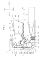
- FIG. 4 is an enlarged sectional view of the periphery of the photoconductive drum 31 and the fixing unit 40 according to this embodiment.
- FIG. 5 is a perspective view partly in section showing the periphery of the fixing unit 40 and
- FIG. 6 is a plan view partly in section of the image forming apparatus 1.
- a sheet fed from the sheet cassette 21 ( FIG. 3 ) arranged in a lower part of the main body housing 10 is conveyed from a lower side toward an upper side along the main conveyance path 22F (sheet conveyance path).
- the drum unit 30H image bearing member unit
- the drum unit 30H is arranged to face the main conveyance path 22F at a predetermined position (first position) of the main conveyance path 22F.
- a toner image is transferred to the sheet being conveyed between the photoconductive drum 31 and the transfer roller 34 in the drum unit 30H.
- the fixing unit 40 is arranged to face the main conveyance path 22F at a position (second position) of the main conveyance path 22F downstream of the drum unit 30H in a conveying direction and above the drum unit 30H to face the main conveyance path 22F.
- the sheet having the toner image transferred thereto is subjected to a fixing process while being nipped between the fixing roller 41 and the pressure roller 42 in the fixing unit 40.
- the sheet having passed through the fixing unit 40 is conveyed further upward and discharged to the sheet discharging portion 13 through the sheet discharge opening 14 by the pair of discharge rollers 24.
- the fixing unit 40 is arranged above the drum unit 30H housing the photoconductive drum 31.
- the cleaning device 35 for cleaning the surface of the photoconductive drum 31 is arranged at a position closest to the fixing unit 40.
- the cleaning device 35 is covered by an upper surface portion 35H of the drum unit 30H.
- the upper surface portion 35H is a cleaner housing for housing the cleaning device 35.
- the upper surface portion 35H is connected to the drum unit 30H.
- the cleaning device 35 includes a plate-like cleaning blade 35B which is held in contact with a vertically uppermost part of the photoconductive drum 31 at a predetermined angle.
- the cleaning device 35 includes a conveyor screw 35S for conveying the toner to the unillustrated collecting device. As the photoconductive drum 31 is rotated in a direction of an arrow D1, the toner scraped off by the cleaning blade 35B is stored into the upper surface portion 35H (cleaner housing) and conveyed toward the unillustrated collecting device by the conveyor screw 35S.
- a distance between the upper surface portion 35H of the drum unit 30H and the fixing housing 40H housing the fixing unit 40 is only about 20 to 30 mm. Accordingly, heat generated by the fixing roller 41 heated to apply the fixing process to a sheet tends to be transferred to the cleaning device 35. If the cleaning device 35 is warmed by this heat, the toner contained inside tends to be softened. A temperature at which the softening of the toner starts differs depending on a toner material used. A glass transition temperature which is one characteristic of a resin material is used as an index for the softening of the toner.
- the softening of the toner starts when toner temperature exceeds 40°C to 50°C which is a glass transition temperature.
- the softening of the toner having occurred in the cleaning device 35 changes outer shapes of toner particles and causes the aggregation of a plurality of toner particles.
- the aggregated toner particles hinder the conveyance of the toner to the collecting device (not shown) by the conveyor screw 35S and causes incorrect rotation of the conveyor screw 35S, a torque increase and the like. As a result, a failure of the image forming apparatus 1 occurs.
- a first air passage r1 and a second air passage r2 are arranged between the cleaning device 35 and the fixing unit 40 in this embodiment.
- the first and second air passages r1, r2 are arranged before the main conveyance path 22F in the image forming apparatus 1.
- the structures of the first and second air passages r1, r2 are described with reference to FIGS. 4 and 5 .
- the first and second air passages r1, r2 are formed by the fixing housing 40H, the drum unit 30H and a frame supporting the main body housing 10.
- the fixing housing 40H includes a fixing roller supporting portion 41B ( FIG. 5 ), a fixing unit standing wall 40T and a fixing housing bottom portion 40L (wall portion).
- a bearing for supporting the fixing roller 41 is fitted into the fixing roller supporting portion 41B.
- the fixing unit standing wall 40T stands in a vertical direction at a side of the fixing roller 41 opposite to the main conveyance path 22F.
- the fixing housing bottom portion 40L is arranged below the fixing roller 41 to form a bottom part of the fixing housing 40H.
- the fixing housing bottom portion 40L is connected at an angle to the lower end of the fixing unit standing wall 40T.
- the fixing unit standing wall 40T and the fixing housing bottom portion 40L are in an inverted T-shaped arrangement when viewed sideways.
- the fixing housing bottom portion 40L is arranged to face the drum unit 30H located below the fixing unit 40. Further, a rear part of the fixing housing bottom portion 40L is arranged to face the fixing roller 41 below the fixing roller 41. On the other hand, a front part of the fixing housing bottom portion 40L extends away from the fixing roller 41 and is arranged to face a main body standing wall lower portion 10M to be described later.
- the main body housing 10 includes a heat insulation frame 10S, the main body standing wall lower portion 10M, vents 76, a main body standing wall upper portion 10H and louvers 75.
- the heat insulation frame 10S is arranged in parallel to the fixing housing bottom portion 40L below the fixing housing bottom portion 40L.
- the heat insulation frame 10S is a part of the frame supporting the main body housing 10.
- the heat insulation frame 10S is a plate member substantially horizontally arranged from the left frame 10L to the right frame 10R (see FIG. 2 ) when viewed from front.
- a leading end portion 10Sa (one end) of the heat insulation frame 10S is arranged to face the main conveyance path 22F while being spaced apart therefrom by a predetermined distance ( FIGS. 4 and 5 ).
- the heat insulation frame 10S is arranged such that an end (other end) opposite to the leading end portion 10Sa extends away from the main conveyance path 22F.
- the heat insulation frame 10S has a function of insulating (shielding) heat between the fixing unit 40 and the cleaning device 35.
- the main body standing wall lower portion 10M faces the heat insulation frame 10S and the fixing housing bottom portion 40L at a side of the heat insulation frame 10S opposite to the main conveyance path 22F and stands in the vertical direction.
- the main body standing wall lower portion 10M is a part of a cover member of the main body housing 10 and connected at a right angle to a front end part of the heat insulation frame 10S. Further, the main body standing wall lower portion 10M faces the fixing housing bottom portion 40L at a facing portion E3 ( FIG. 4 ).
- the vents 76 are arranged near a boundary between the heat insulation frame 10S and the main body standing wall lower portion 10M.
- the vents 76 are openings formed to penetrate though a part of the heat insulation frame 10S. As shown in FIG. 6 , the vents 76 are arranged at a plurality of positions of the heat insulation frame 10S spaced apart in the lateral direction.
- the main body standing wall upper portion 10H is a part of the cover member of the main body housing 10 and is vertically arranged while being connected to an upper part of the main body standing wall lower portion 10M.
- An upper end part of the main body standing wall upper portion 10H forms the lower end of the sheet discharge opening 14 through which a sheet is to be discharged.
- the louvers 75 are composed of a plurality of slits formed on an upper end side of the main body standing wall upper portion 10H below the sheet discharge opening 14.
- the plurality of slits forming the louvers 75 are arranged in the vertical and lateral directions of the main body standing wall upper portion 10H (see FIG. 1 ).
- the louvers 75 are arranged on the upper end part of the main body standing wall upper portion 10H.
- the louvers 75 are arranged at a distance in the vertical direction from sheets stacked on the sheet discharging portion 13.
- the first air passage r1 is composed of a first horizontal air passage r11 (first hot air exhaust passage) arranged substantially in the horizontal direction and a first vertical air passage r12 (second hot air exhaust passage) arranged substantially in the vertical direction.
- the first horizontal air passage r11 is arranged between the heat insulation frame 10S and the upper surface portion 35H of the drum unit 30H.
- the first vertical air passage r12 is arranged to extend upward from an area E2 formed by the vents 76 along the main body standing wall lower portion 10M and the main body standing wall upper portion 10H up to the louvers 75.
- the first horizontal air passage r11 and the first vertical air passage r12 are allowed to communicate by the vents 76.
- the second air passage r2 is composed of a second horizontal air passage r21 (third hot air exhaust passage) arranged substantially in the horizontal direction and a second vertical air passage r22 arranged substantially in the vertical direction.
- the second horizontal air passage r21 is formed between the fixing housing bottom portion 40L and the heat insulation frame 10S.
- the second horizontal air passage r21 includes a first flow inlet E1 (opening) on the side of the leading end portion 10Sa of the heat insulation frame 10S.
- the first flow inlet E1 is defined by an end portion 40La ( FIG. 5 ) of the fixing housing bottom portion 40L on the side of the main conveyance path 22F and the leading end portion 10Sa of the heat insulation frame 10S on the side of the main conveyance path 22F.
- the second vertical air passage r22 is arranged in an area from the facing portion E3 to the louvers 75 along the main body standing wall lower portion 10M and the main body standing wall upper portion 10H.
- the first vertical air passage r12 and the second vertical air passage r22 are so arranged as to join at the facing portion E3 and, thereafter, share a path up to the louvers 75.
- the second horizontal air passage r21 communicates with the second vertical air passage r22 at a communication port 77 arranged at a side opposite to the leading end portion 10Sa.
- first and second air passages r1, r2 functions of the first and second air passages r1, r2 according to this embodiment are described with reference to FIG. 4 .
- the operation of the image forming apparatus 1 is performed, the fixing roller 41 is heated and a sheet is conveyed upward along the main conveyance path 22F. At this time, air on a sheet surface moves together with the sheet to produce a laminar flow as the sheet is conveyed. Then, this laminar flow (air flow in the sheet conveyance path) enters the first horizontal air passage r11 from the leading end portion 10Sa of the heat insulation frame 10S by conveying the sheet from the photoconductive drum 31 toward the fixing unit 40. As a result, an air flow moving toward the main body standing wall lower portion 10M (front side) is produced in the first horizontal air passage r11.
- This air flow further moves toward the main body standing wall lower portion 10M in the first horizontal air passage r11 due to the momentum of the flow itself and a function of being pushed by the laminar flow further fed from the main conveyance path 22F. Then, this air flow exits through the vents 76 and enters the first vertical air passage r12 and, after ascending, is discharged to the outside of the apparatus.
- the laminar flow produced by the sheet being conveyed contacts the upper surface portion 35H of the drum unit 30H when passing along the first horizontal air passage r11.
- the upper surface portion 35H is cooled by the laminar flow.
- This can suppress the transfer of heat from the fixing unit 40 to the drum unit 30H.
- This suppresses the softening and aggregation of the toner adhering to the photoconductive drum 31 in the drum unit 30H.
- an increase in the rotational torque of the photoconductive drum 31 and the adhesion of the toner to the surface of the photoconductive drum 31 due to the softened and aggregated toner are prevented.
- the cooling fan 80 arranged at a lower part of the left cover 12L to cool the board unit 70 introduces an air flow into the interior of the main body housing 10 through the air inlet 12La (see FIGS. 1 and 2 ).
- new air is easily introduced into a lower space in the main body housing 10. Therefore, a laminar flow moving upward is more easily produced by a sheet being conveyed upward along the main conveyance path 22F.
- the heat insulation frame 10S effectively insulates heat transferred from the fixing roller 41 of the fixing unit 40 toward the drum unit 30H.
- the second horizontal air passage r21 is arranged between the heat insulation frame 10S and the fixing housing bottom portion 40L.
- air in a space A ( FIG. 5 ) between the fixing housing bottom portion 40L and the heat insulation frame 10S is warmed.
- the density of this air decreases due to a temperature increase and the air tries to ascend.
- the heat insulation frame 10S and the fixing housing bottom portion 40L are arranged horizontally to each other.
- the leading end portion 10Sa of the heat insulation frame 10S is bent upward in advance (bent portion).
- the communication port 77 has a larger opening cross-sectional area than the first flow inlet E1.
- heat generated from the fixing roller 41 is transferred from the fixing housing bottom portion 40L to the air in the space A.
- This air produces a natural convection, enters the second vertical air passage r22 from the second horizontal air passage r21 and is discharged via the louvers 75. Since the louvers 75 are arranged on the upper end part of the main body standing wall upper portion 10H, the flow of warm air to the sheets stacked on the sheet discharging portion 13 is suppressed. Thus, the re-melting of the toner image on the sheet is suppressed.
- the heat insulation frame 10S effectively insulates heat between the fixing unit 40 and the cleaning device 35.
- the laminar flow produced by the sheet being conveyed cools the cleaning device 35 and blocks heat transferred from the fixing unit 40 as an air curtain while passing along the first horizontal air passage r11.
- the warmed air flow is discharged via the louvers 75 from the first vertical air passage r12.
- the air flow having passed through the first horizontal air passage r11 and that exiting from the second horizontal air passage r21 join at the facing portion E3.
- the exhaust efficiency of each air flow is enhanced and a heat insulation effect between the fixing unit 40 and the cleaning device 35 is promoted more.
- the air flow having entered the first horizontal air passage r11 enters the first vertical air passage r12 through the vents 76 formed in the heat insulation frame 10S. At this time, the air flow enters the first vertical air passage r12 while being squeezed to have a cross-sectional area corresponding to the opening cross-sectional area of the vents 76.
- the air flow entering the first vertical air passage r12 from the first horizontal air passage r11 and that entering the first vertical air passage r12 from the second horizontal air passage r21 are easily mixed.
- the heat radiation member 80D is a plate made of a metal material having high heat radiation performance.
- the heat radiation member 80D includes a horizontal portion 80L (first surface) and a vertical portion 80U (second surface).
- the plate is bent in advance so that the vertical portion 80U intersects at a right angle to the horizontal portion 80L.
- the horizontal portion 80L is arranged between the fixing housing bottom portion 40L and the heat insulation frame 10S.
- the vertical portion 80U extends upward substantially at a right angle from the horizontal portion 80L near a main body standing wall 10N.
- a third horizontal air passage r31 is arranged below the heat insulation frame 10S and a third vertical air passage r32 perpendicular to the third horizontal air passage r21 is arranged to extend upward at a downstream side of the third horizontal portion r31.
- a fourth horizontal air passage r41 is split into a fifth horizontal air passage r41a and a sixth horizontal air passage r41b by the horizontal portion 80L between the heat insulation frame 10S and the fixing housing bottom portion 40L.
- the third vertical air passage r32 and the fourth vertical air passage r42 are formed before and after the vertical portion 80U.
- a laminar flow formed by a sheet being conveyed along the main conveyance path 22F is discharged to the outside of the apparatus from the louvers 75 via the third horizontal air passage r31 and the third vertical air passage r32.
- air warmed between the fixing housing bottom portion 40L and the heat insulation frame 10S moves toward the horizontal portion 80L in the fourth horizontal air passage r41.
- this air flow is split into two upper and lower flows by the horizontal portion 80L.
- the one moving along the fifth horizontal portion r41a collides with the vertical portion 80U to change its moving direction to move vertically upward and enters the fourth vertical air passage r42.
- the air flow moving upward along the fourth vertical air passage r42 joins the air flow having moved along the third vertical air passage r32 above the horizontal portion 80L.
- the one moving along the sixth horizontal air passage r41b enters the third horizontal air passage r31 below the vertical portion 80U and is discharged to the outside of the apparatus via the third vertical air passage r32.
- the horizontal portion 80L absorbs heat from the air flows moving in the fifth and sixth horizontal air passages r41a and r41b and transfers it to the vertical portion 80U.
- the heat transferred to the vertical portion 80U is radiated to the air flows ascending in the third and fourth vertical air passages r32, r42.
- the heat radiation member 80D functions as a heat sink and can transfer the heat generated from the fixing unit 40 in the plate and radiate the heat to the vertical air passage.
- the heat radiation member 80D has a function of shielding infrared rays radiated from the fixing unit 40 to the cleaning device 35.
Landscapes
- Physics & Mathematics (AREA)
- General Physics & Mathematics (AREA)
- Life Sciences & Earth Sciences (AREA)
- Engineering & Computer Science (AREA)
- Atmospheric Sciences (AREA)
- Biodiversity & Conservation Biology (AREA)
- Ecology (AREA)
- Environmental & Geological Engineering (AREA)
- Environmental Sciences (AREA)
- Control Or Security For Electrophotography (AREA)
- Fixing For Electrophotography (AREA)
- Electrophotography Configuration And Component (AREA)
Abstract
Description
- This application is based on Japanese Patent Application Serial No.
2011-288346 - The present disclosure relates to an image forming apparatus for applying an image forming process to a sheet and particularly to an image forming apparatus with a hot air exhaust passage for exhausting heat generated from a fixing unit to the outside of the apparatus.
- An image forming apparatus is provided with various components and members which serve as heat sources and devices including them. For example, a fixing device for applying a fixing process to a sheet having a toner image transferred thereto can be cited as such. To discharge heat generated by these heat source devices, the image forming apparatus is provided with a hot air exhaust passage for heat exhaust.
- A fan for promoting the heat exhaust is generally mounted on an end part of the above hot air exhaust passage. Due to the operation of the fan, an air flow is generated in the hot air exhaust passage and warm air in the apparatus is discharged to the outside of the apparatus by this air flow. Conventionally, there has been disclosed a technology for causing an air flow generated by the suction of the fan to enter an image forming apparatus and causing heat generated by heat source devices such as a fixing unit to be exhausted.
- An area around the fixing unit tends to get hot in the image forming apparatus. If a device containing a toner is arranged in such an area, the toner may be softened or a plurality of toner particles may be aggregated. As a result, various problems occur in the image forming apparatus. Thus, it is required to exhaust warm air in the area near the fixing unit. However, a cost increase of the entire apparatus is brought about if a fan dedicated for the fixing unit is arranged as in the above conventional technology.
- The present disclosure was made in view of the above problem and aims to enhance a heat insulation effect between a fixing unit and peripheral devices.
- An image forming apparatus according to one aspect of the present disclosure includes a housing, a sheet conveyance path, a toner containing unit, a fixing unit, a fixing housing, a heat insulation member, a first hot air exhaust passage, a second hot air exhaust passage and a third hot air exhaust passage. The sheet conveyance path is arranged to extend from a lower side toward an upper side in the housing. The toner containing unit is arranged to face the sheet conveyance path at a first position of the sheet conveyance path and contains a toner inside. The fixing unit faces the sheet conveyance path at a second position of the sheet conveyance path downstream of the first position in a conveying direction and applies a fixing process to the sheet. The fixing housing houses the fixing unit and includes a wall portion facing the toner containing unit. One end of the heat insulation member faces the sheet conveyance path, the other end thereof extends away from the sheet conveyance path and the heat insulation member shields between the wall portion and the toner containing unit. The first hot air exhaust passage is arranged between the heat insulation member and the toner containing unit. The second hot air exhaust passage communicates with the first hot air exhaust passage at the other end of the heat insulation member. The third hot air exhaust passage is arranged between the wall portion and the heat insulation member and includes an opening facing the sheet conveyance path at the one end of the heat insulation member and a communication port communicating with the second hot air exhaust passage at the other end of the heat insulation member.
- These and other objects, features and advantages of the present disclosure will become more apparent upon reading the following detailed description along with the accompanying drawings.
-
-
FIG. 1 is a perspective view showing the external appearance of an image forming apparatus according to one embodiment of the present disclosure, -
FIG. 2 is a perspective view showing the internal structure of the image forming apparatus according to the one embodiment of the present disclosure, -
FIG. 3 is a side view in section showing the internal structure of the image forming apparatus according to the one embodiment of the present disclosure, -
FIG. 4 is a sectional view for explaining hot air exhaust passages of the image forming apparatus according to the one embodiment of the present disclosure, -
FIG. 5 is a perspective view partly in section for explaining the hot air exhaust passages of the image forming apparatus according to the one embodiment of the present disclosure, -
FIG. 6 is a plan view partly in section for explaining the hot air exhaust passages of the image forming apparatus according to the one embodiment of the present disclosure, and -
FIG. 7 is a sectional view for explaining hot air exhaust passages of an image forming apparatus according to another embodiment of the present disclosure. - Hereinafter, an embodiment of the present disclosure is described based on the drawings.
FIG. 1 is a perspective view showing the external appearance of animage forming apparatus 1 according to one embodiment of the present disclosure. Further,FIG. 2 is a perspective view showing the internal structure of theimage forming apparatus 1 according to the one embodiment of the present disclosure.FIG. 2 shows a state where covers and an image forming unit 30 to be described later are removed in a state ofFIG. 1 . Furthermore,FIG. 3 is a side view in section showing the internal structure of theimage forming apparatus 1 according to the one embodiment of the present disclosure. Although a black-and-white printer is illustrated as theimage forming apparatus 1 here, the image forming apparatus may be a copier, a facsimile machine or a complex machine provided with these functions or may be an image forming apparatus for forming a color image. - The
image forming apparatus 1 includes a main body housing 10 (housing) having a substantially rectangular parallelepiped housing structure, asheet feeding unit 20, the image forming unit 30, afixing unit 40, atoner container 50, aboard unit 70 and acooling fan 80 housed in thismain body housing 10. - A
front cover 11 and arear cover 12 are respectively provided on a front surface side and a rear surface side of themain body housing 10. By opening thefront cover 11, thetoner container 50 is exposed as shown inFIG. 2 . This enables a user to take out thetoner container 50 from the front surface side of the main body housing 10 when a toner runs out. Therear cover 12 is a cover which is opened at the time of a sheet jam or maintenance. The respective image forming unit 30 andfixing unit 40 can be taken out from the rear surface side of themain body housing 10 by opening therear cover 12. Further, aleft cover 12L (FIG. 1 ) and a right cover 12R (not shown inFIG. 1 ) opposite to theleft cover 12L are respectively so arranged on side surfaces of themain body housing 10 as to extend in a vertical direction. An air inlet 12La through which air is taken by thecooling fan 80 to be described later is arranged in a front part of theleft cover 12L. Further, asheet discharging portion 13 to which a sheet after image formation is to be discharged is provided on the upper surface of themain body housing 10. Various devices for performing image formation are housed in an inner space S (FIG. 2 ) defined by thefront cover 11, therear cover 12, theleft cover 12L, the right cover 12R and thesheet discharging portion 13. - A
left frame 10L and aright frame 10R which are exposed by removing thefront cover 11, therear cover 12, theleft cover 12L and right cover 12R stand in the main body housing 10 (FIG. 2 ). Theleft frame 10L supports various devices on the side of theleft cover 12L of themain body housing 10. Further, theright frame 10R supports various devices on the side of the right cover 12R of themain body housing 10. The image forming unit 30 and thefixing unit 40 extending in a lateral direction are supported by theleft frame 10L and theright frame 10R. Further, afront frame 10F extending between the left andright frames main body housing 10. Furthermore, aninner cover 11B for covering a front inner part of themain body housing 10 is arranged below thefront frame 10F. Theinner cover 11B is arranged from theleft frame 10L to theright frame 10R while facing an upper surface part of asheet cassette 21. Further, ends of thefront frame 10F and theinner cover 11B on the side of theleft frame 10L are respectively partly cut out. A front opening 10F1 is formed at this cut-out part and thetoner container 50 to be described later is housed therein. - The
sheet feeding unit 20 includes thesheet cassette 21 storing sheets to which an image forming process is to be applied (FIG. 3 ). A part of thissheet cassette 21 projects further forward from the front surface of themain body housing 10. The upper surface of a part of thesheet cassette 21 housed in themain body housing 10 is covered by a sheetcassette ceiling plate 21U. Thesheet cassette 21 includes a sheet storage space in which a stack of sheets is stored, a lift plate for lifting up the stack of sheet for sheet feeding and the like. Asheet pickup unit 21A is provided above a rear end side of thesheet cassette 21. Afeed roller 21B for picking up the uppermost sheet of the sheet stack in thesheet cassette 21 one by one is arranged in thissheet pickup unit 21A. - The image forming unit 30 performs an image forming process for forming a toner image on a sheet fed from the
sheet feeding unit 20. The image forming unit 30 includes a photoconductive drum 31 (image bearing member) and a chargingdevice 32, an exposure device (not shown inFIG. 3 ), a developingdevice 33, atransfer roller 34 and acleaning device 35 arranged around thisphotoconductive drum 31. The image forming unit 30 is arranged between theleft cover 12L and the right cover 12R, more specifically between theleft frame 10L and theright frame 10R. - The
photoconductive drum 31 is rotated about its shaft and an electrostatic latent image and a toner image are formed on the circumferential surface thereof. A photoconductive drum made of an amorphous silicon (a-Si) material can be used as thephotoconductive drum 31. The chargingdevice 32 is for uniformly charging the surface of thephotoconductive drum 31 and includes a charging roller held in contact with thephotoconductive drum 31. Thecleaning device 35 includes a cleaning blade and the like and cleans the toner adhering to the circumferential surface of thephotoconductive drum 31 after the transfer of the toner image and conveys the toner to an unillustrated collecting device. Further, thephotoconductive drum 31, the chargingdevice 32 and thecleaning device 35 are integrally configured as adrum unit 30H (seeFIG. 4 ). - The exposure device includes optical devices such as a laser light source, a mirror and a lens and irradiates the circumferential surface of the
photoconductive drum 31 with light modulated based on image data given from an external apparatus such as a personal computer, thereby forming an electrostatic latent image. The developingdevice 33 supplies a toner to the circumferential surface of thephotoconductive drum 31 to develop the electrostatic latent image formed on thephotoconductive drum 31 and form a toner image. The developingdevice 33 includes a developingroller 331 for bearing the toner to be supplied to thephotoconductive drum 31 and afirst conveyor screw 332 and asecond conveyor screw 333 for conveying a developer in a circulating manner while agitating the developer in an unillustrated development housing. - The
transfer roller 34 is a roller for transferring the toner image formed on the circumferential surface of thephotoconductive drum 31 onto a sheet and forms a transfer nip portion together with thephotoconductive drum 31. A transfer bias having a polarity opposite to that of the toner is applied to thistransfer roller 34. - The fixing
unit 40 performs a fixing process for fixing a transferred toner image onto a sheet. The fixingunit 40 includes a fixingroller 41 internally provided with a heat source and apressure roller 42 pressed in contact with this fixingroller 41 and forming a fixing nip portion together with the fixingroller 41. When a sheet having a toner image transferred thereto is passed through the fixing nip portion, the toner image is fixed onto the sheet by heating by the fixingroller 41 and pressing by thepressure roller 42. The fixingunit 40 is housed in a box-shaped fixinghousing 40H (seeFIG. 4 ). - The
toner container 50 stores the toner to be supplied to the developingdevice 33. Thetoner container 50 includes a containermain body 51 as a main storage part for the toner, atubular portion 52 projecting from a lower part of one side surface of the containermain body 51, alid member 53 covering the other side surface of the containermain body 51, and arotary member 54 housed in the container for conveying the toner. The toner stored in thetoner container 50 is supplied into the developingdevice 33 through atoner discharge opening 521 provided on the lower surface of the leading end of thetubular portion 52 by driving and rotating therotary member 54. Thistoner container 50 is arranged at an upper position at an inner side of theleft frame 10L (FIG. 2 ). Further, acontainer ceiling plate 50H covering an upper side of thetoner container 50 is located below the sheet discharging portion 13 (seeFIG. 3 ). - A
main conveyance path 22F (sheet conveyance path) and a reversingconveyance path 22B are provided to convey a sheet in themain body housing 10. Themain conveyance path 22F extends from thesheet pickup unit 21A of thesheet feeding unit 20 to a sheet discharge opening 14 provided to face thesheet discharge portion 13 on the upper surface of themain body housing 10 by way of the image forming unit 30 and the fixingunit 40. The reversingconveyance path 22B is a conveyance path for returning a sheet, one side of which is printed, to a side of themain conveyance path 22F upstream of the image forming unit 30 in the case of printing both sides of the sheet. - A pair of
registration rollers 23 are arranged in a side of themain conveyance path 22F upstream of the transfer nip portion between thephotoconductive drum 31 and thetransfer roller 34. A sheet is temporarily stopped at the pair ofregistration rollers 23 and fed to the transfer nip portion at a predetermined timing for image transfer after a skew correction is made. A plurality of conveyor rollers for conveying a sheet are arranged at suitable positions of themain conveyance path 22F and the reversingconveyance path 22B, and a pair ofdischarge rollers 24 are arranged, for example, near thesheet discharge opening 14. - The reversing
conveyance path 22B is formed between the outer side surface of a reversingunit 25 and the inner surface of therear cover 12 of themain body housing 10. Note that thetransfer roller 34 and one of the pair ofregistration rollers 23 are mounted on the inner side surface of the reversingunit 25. Therear cover 12 and the reversingunit 25 are respectively rotatable about a supportingpoint portion 121 provided at the lower ends thereof. If a sheet jam occurs in therear conveyance path 22B, therear cover 12 is opened. If a sheet jam occurs in themain conveyance path 22F or if the unit including thephotoconductive drum 31 or the developingdevice 33 is taken out to the outside, the reversingunit 25 is also opened in addition to therear cover 12. - The
board unit 70 is arranged on the outer (right) side surface of theright frame 10R when viewed from front (FIG. 2 ). A plurality of circuit boards are consolidated and arranged in theboard unit 70. - The cooling
fan 80 is arranged on the outer (left) side surface of theleft frame 10L when viewed from front and at a front position of themain body housing 10. The coolingfan 80 includes an unillustrated rotary shaft, a motor and a plurality of blade members. The coolingfan 80 rotates when a drive current is supplied to the motor from an unillustrated power supply and rotates while forming a plane of rotation parallel to theleft frame 10L. By the rotation of the coolingfan 80, air outside themain body housing 10 is sucked through the air inlet 12La to produce an air flow moving toward the interior of themain body housing 10. In this embodiment, the coolingfan 80 is arranged mainly for the purpose of cooling theboard unit 70. The air flow entering the interior of themain body housing 10 is blown toward a lower part of theboard unit 70 while passing through a space located below theinner cover 11B and above thesheet cassette 21. - Next, the configuration of peripheral parts of the
photoconductive drum 31 and the fixingunit 40 is described with reference toFIGS. 4 to 6 .FIG. 4 is an enlarged sectional view of the periphery of thephotoconductive drum 31 and the fixingunit 40 according to this embodiment. Further,FIG. 5 is a perspective view partly in section showing the periphery of the fixingunit 40 andFIG. 6 is a plan view partly in section of theimage forming apparatus 1. - With reference to
FIG. 4 , a sheet fed from the sheet cassette 21 (FIG. 3 ) arranged in a lower part of themain body housing 10 is conveyed from a lower side toward an upper side along themain conveyance path 22F (sheet conveyance path). Thedrum unit 30H (image bearing member unit) is arranged to face themain conveyance path 22F at a predetermined position (first position) of themain conveyance path 22F. A toner image is transferred to the sheet being conveyed between thephotoconductive drum 31 and thetransfer roller 34 in thedrum unit 30H. The fixingunit 40 is arranged to face themain conveyance path 22F at a position (second position) of themain conveyance path 22F downstream of thedrum unit 30H in a conveying direction and above thedrum unit 30H to face themain conveyance path 22F. The sheet having the toner image transferred thereto is subjected to a fixing process while being nipped between the fixingroller 41 and thepressure roller 42 in the fixingunit 40. The sheet having passed through the fixingunit 40 is conveyed further upward and discharged to thesheet discharging portion 13 through the sheet discharge opening 14 by the pair ofdischarge rollers 24. - As just described, in this embodiment, the fixing
unit 40 is arranged above thedrum unit 30H housing thephotoconductive drum 31. In thedrum unit 30H, thecleaning device 35 for cleaning the surface of thephotoconductive drum 31 is arranged at a position closest to the fixingunit 40. - An upper part of the
cleaning device 35 is covered by anupper surface portion 35H of thedrum unit 30H. Theupper surface portion 35H is a cleaner housing for housing thecleaning device 35. Theupper surface portion 35H is connected to thedrum unit 30H. Thecleaning device 35 includes a plate-like cleaning blade 35B which is held in contact with a vertically uppermost part of thephotoconductive drum 31 at a predetermined angle. Further, thecleaning device 35 includes aconveyor screw 35S for conveying the toner to the unillustrated collecting device. As thephotoconductive drum 31 is rotated in a direction of an arrow D1, the toner scraped off by thecleaning blade 35B is stored into theupper surface portion 35H (cleaner housing) and conveyed toward the unillustrated collecting device by theconveyor screw 35S. - In this embodiment, to maximally reduce the size of the
image forming apparatus 1, a distance between theupper surface portion 35H of thedrum unit 30H and the fixinghousing 40H housing the fixingunit 40 is only about 20 to 30 mm. Accordingly, heat generated by the fixingroller 41 heated to apply the fixing process to a sheet tends to be transferred to thecleaning device 35. If thecleaning device 35 is warmed by this heat, the toner contained inside tends to be softened. A temperature at which the softening of the toner starts differs depending on a toner material used. A glass transition temperature which is one characteristic of a resin material is used as an index for the softening of the toner. For example, if a polyether-based resin is used as a main material of the toner, the softening of the toner starts when toner temperature exceeds 40°C to 50°C which is a glass transition temperature. The softening of the toner having occurred in thecleaning device 35 changes outer shapes of toner particles and causes the aggregation of a plurality of toner particles. The aggregated toner particles hinder the conveyance of the toner to the collecting device (not shown) by theconveyor screw 35S and causes incorrect rotation of theconveyor screw 35S, a torque increase and the like. As a result, a failure of theimage forming apparatus 1 occurs. - To solve such a problem, a first air passage r1 and a second air passage r2 are arranged between the cleaning
device 35 and the fixingunit 40 in this embodiment. The first and second air passages r1, r2 are arranged before themain conveyance path 22F in theimage forming apparatus 1. The structures of the first and second air passages r1, r2 are described with reference toFIGS. 4 and5 . - The first and second air passages r1, r2 are formed by the fixing
housing 40H, thedrum unit 30H and a frame supporting themain body housing 10. - The fixing
housing 40H includes a fixingroller supporting portion 41B (FIG. 5 ), a fixingunit standing wall 40T and a fixinghousing bottom portion 40L (wall portion). A bearing for supporting the fixingroller 41 is fitted into the fixingroller supporting portion 41B. The fixingunit standing wall 40T stands in a vertical direction at a side of the fixingroller 41 opposite to themain conveyance path 22F. The fixinghousing bottom portion 40L is arranged below the fixingroller 41 to form a bottom part of the fixinghousing 40H. The fixinghousing bottom portion 40L is connected at an angle to the lower end of the fixingunit standing wall 40T. The fixingunit standing wall 40T and the fixinghousing bottom portion 40L are in an inverted T-shaped arrangement when viewed sideways. The fixinghousing bottom portion 40L is arranged to face thedrum unit 30H located below the fixingunit 40. Further, a rear part of the fixinghousing bottom portion 40L is arranged to face the fixingroller 41 below the fixingroller 41. On the other hand, a front part of the fixinghousing bottom portion 40L extends away from the fixingroller 41 and is arranged to face a main body standing walllower portion 10M to be described later. - Further, the
main body housing 10 includes aheat insulation frame 10S, the main body standing walllower portion 10M, vents 76, a main body standing wallupper portion 10H andlouvers 75. - The
heat insulation frame 10S is arranged in parallel to the fixinghousing bottom portion 40L below the fixinghousing bottom portion 40L. Theheat insulation frame 10S is a part of the frame supporting themain body housing 10. Theheat insulation frame 10S is a plate member substantially horizontally arranged from theleft frame 10L to theright frame 10R (seeFIG. 2 ) when viewed from front. When view sideways, a leading end portion 10Sa (one end) of theheat insulation frame 10S is arranged to face themain conveyance path 22F while being spaced apart therefrom by a predetermined distance (FIGS. 4 and5 ). Theheat insulation frame 10S is arranged such that an end (other end) opposite to the leading end portion 10Sa extends away from themain conveyance path 22F. Theheat insulation frame 10S has a function of insulating (shielding) heat between the fixingunit 40 and thecleaning device 35. - The main body standing wall
lower portion 10M faces theheat insulation frame 10S and the fixinghousing bottom portion 40L at a side of theheat insulation frame 10S opposite to themain conveyance path 22F and stands in the vertical direction. The main body standing walllower portion 10M is a part of a cover member of themain body housing 10 and connected at a right angle to a front end part of theheat insulation frame 10S. Further, the main body standing walllower portion 10M faces the fixinghousing bottom portion 40L at a facing portion E3 (FIG. 4 ). - The
vents 76 are arranged near a boundary between theheat insulation frame 10S and the main body standing walllower portion 10M. Thevents 76 are openings formed to penetrate though a part of theheat insulation frame 10S. As shown inFIG. 6 , thevents 76 are arranged at a plurality of positions of theheat insulation frame 10S spaced apart in the lateral direction. - The main body standing wall
upper portion 10H is a part of the cover member of themain body housing 10 and is vertically arranged while being connected to an upper part of the main body standing walllower portion 10M. An upper end part of the main body standing wallupper portion 10H forms the lower end of the sheet discharge opening 14 through which a sheet is to be discharged. - The
louvers 75 are composed of a plurality of slits formed on an upper end side of the main body standing wallupper portion 10H below thesheet discharge opening 14. The plurality of slits forming thelouvers 75 are arranged in the vertical and lateral directions of the main body standing wallupper portion 10H (seeFIG. 1 ). As described above, thelouvers 75 are arranged on the upper end part of the main body standing wallupper portion 10H. Thus, thelouvers 75 are arranged at a distance in the vertical direction from sheets stacked on thesheet discharging portion 13. - The first air passage r1 is composed of a first horizontal air passage r11 (first hot air exhaust passage) arranged substantially in the horizontal direction and a first vertical air passage r12 (second hot air exhaust passage) arranged substantially in the vertical direction.
- The first horizontal air passage r11 is arranged between the
heat insulation frame 10S and theupper surface portion 35H of thedrum unit 30H. - The first vertical air passage r12 is arranged to extend upward from an area E2 formed by the
vents 76 along the main body standing walllower portion 10M and the main body standing wallupper portion 10H up to thelouvers 75. The first horizontal air passage r11 and the first vertical air passage r12 are allowed to communicate by thevents 76. - The second air passage r2 is composed of a second horizontal air passage r21 (third hot air exhaust passage) arranged substantially in the horizontal direction and a second vertical air passage r22 arranged substantially in the vertical direction.
- The second horizontal air passage r21 is formed between the fixing
housing bottom portion 40L and theheat insulation frame 10S. The second horizontal air passage r21 includes a first flow inlet E1 (opening) on the side of the leading end portion 10Sa of theheat insulation frame 10S. The first flow inlet E1 is defined by an end portion 40La (FIG. 5 ) of the fixinghousing bottom portion 40L on the side of themain conveyance path 22F and the leading end portion 10Sa of theheat insulation frame 10S on the side of themain conveyance path 22F. - The second vertical air passage r22 is arranged in an area from the facing portion E3 to the
louvers 75 along the main body standing walllower portion 10M and the main body standing wallupper portion 10H. In this embodiment, the first vertical air passage r12 and the second vertical air passage r22 are so arranged as to join at the facing portion E3 and, thereafter, share a path up to thelouvers 75. The second horizontal air passage r21 communicates with the second vertical air passage r22 at acommunication port 77 arranged at a side opposite to the leading end portion 10Sa. - Next, functions of the first and second air passages r1, r2 according to this embodiment are described with reference to
FIG. 4 . The operation of theimage forming apparatus 1 is performed, the fixingroller 41 is heated and a sheet is conveyed upward along themain conveyance path 22F. At this time, air on a sheet surface moves together with the sheet to produce a laminar flow as the sheet is conveyed. Then, this laminar flow (air flow in the sheet conveyance path) enters the first horizontal air passage r11 from the leading end portion 10Sa of theheat insulation frame 10S by conveying the sheet from thephotoconductive drum 31 toward the fixingunit 40. As a result, an air flow moving toward the main body standing walllower portion 10M (front side) is produced in the first horizontal air passage r11. This air flow further moves toward the main body standing walllower portion 10M in the first horizontal air passage r11 due to the momentum of the flow itself and a function of being pushed by the laminar flow further fed from themain conveyance path 22F. Then, this air flow exits through thevents 76 and enters the first vertical air passage r12 and, after ascending, is discharged to the outside of the apparatus. - In this way, the laminar flow produced by the sheet being conveyed contacts the
upper surface portion 35H of thedrum unit 30H when passing along the first horizontal air passage r11. Thus, theupper surface portion 35H is cooled by the laminar flow. This can suppress the transfer of heat from the fixingunit 40 to thedrum unit 30H. This, in turn, suppresses the softening and aggregation of the toner adhering to thephotoconductive drum 31 in thedrum unit 30H. As a result, an increase in the rotational torque of thephotoconductive drum 31 and the adhesion of the toner to the surface of thephotoconductive drum 31 due to the softened and aggregated toner are prevented. - Further, the cooling
fan 80 arranged at a lower part of theleft cover 12L to cool theboard unit 70 introduces an air flow into the interior of themain body housing 10 through the air inlet 12La (seeFIGS. 1 and2 ). Thus, new air is easily introduced into a lower space in themain body housing 10. Therefore, a laminar flow moving upward is more easily produced by a sheet being conveyed upward along themain conveyance path 22F. - Further, as described above, the
heat insulation frame 10S effectively insulates heat transferred from the fixingroller 41 of the fixingunit 40 toward thedrum unit 30H. - Further, in this embodiment, the second horizontal air passage r21 is arranged between the
heat insulation frame 10S and the fixinghousing bottom portion 40L. When the fixingroller 41 is heated and the fixinghousing 40H is warmed, air in a space A (FIG. 5 ) between the fixinghousing bottom portion 40L and theheat insulation frame 10S is warmed. The density of this air decreases due to a temperature increase and the air tries to ascend. Here, theheat insulation frame 10S and the fixinghousing bottom portion 40L are arranged horizontally to each other. However, as shown inFIG. 4 , the leading end portion 10Sa of theheat insulation frame 10S is bent upward in advance (bent portion). Thus, thecommunication port 77 has a larger opening cross-sectional area than the first flow inlet E1. As a result, in the space A, pressure of air is lower on the side of thecommunication port 77 than on the side of the first flow inlet E1. Therefore, the air warmed in the space A becomes an air flow and moves toward the main body standing walllower portion 10M. The air flow having reached thecommunication port 77 enters the second vertical air passage r22 (first vertical air passage r12) and, after ascending along the main body standing walllower portion 10M and the main body standing wallupper portion 10H, is discharged from thelouvers 75. - When the air warmed in the space A moves toward the main body standing wall
lower portion 10M, the pressure in the space A becomes lower than the pressure of the air around themain conveyance path 22F. As a result, the air around themain conveyance path 22F flows into the space A through the first flow inlet E1. When the flowed-in air is warmed again, an air flow, which will move toward the main body standing walllower portion 10M, is similarly formed. - As just described, in this embodiment, heat generated from the fixing
roller 41 is transferred from the fixinghousing bottom portion 40L to the air in the space A. This air produces a natural convection, enters the second vertical air passage r22 from the second horizontal air passage r21 and is discharged via thelouvers 75. Since thelouvers 75 are arranged on the upper end part of the main body standing wallupper portion 10H, the flow of warm air to the sheets stacked on thesheet discharging portion 13 is suppressed. Thus, the re-melting of the toner image on the sheet is suppressed. - Further, the
heat insulation frame 10S effectively insulates heat between the fixingunit 40 and thecleaning device 35. In addition, the laminar flow produced by the sheet being conveyed cools thecleaning device 35 and blocks heat transferred from the fixingunit 40 as an air curtain while passing along the first horizontal air passage r11. By cooling thecleaning device 35, the warmed air flow is discharged via thelouvers 75 from the first vertical air passage r12. - By the above configuration, heat insulation between the fixing
unit 40 and thecleaning device 35 is realized without providing such a dedicated fan as to directly blow an air flow to the fixingunit 40 and thecleaning device 35. This suppresses the softening and aggregation of the toner adhering to thecleaning blade 35B in thecleaning device 35. As a result, the adhesion of the softened and aggregated toner to thecleaning blade 35B is prevented. - Further, in this embodiment, the air flow having passed through the first horizontal air passage r11 and that exiting from the second horizontal air passage r21 join at the facing portion E3. Thus, the exhaust efficiency of each air flow is enhanced and a heat insulation effect between the fixing
unit 40 and thecleaning device 35 is promoted more. - Further, according to the above embodiment, the air flow having entered the first horizontal air passage r11 enters the first vertical air passage r12 through the
vents 76 formed in theheat insulation frame 10S. At this time, the air flow enters the first vertical air passage r12 while being squeezed to have a cross-sectional area corresponding to the opening cross-sectional area of thevents 76. Thus, the air flow entering the first vertical air passage r12 from the first horizontal air passage r11 and that entering the first vertical air passage r12 from the second horizontal air passage r21 are easily mixed. - Although the
image forming apparatus 1 including the hot air exhaust passages according to the embodiment of the present disclosure has been described above, the present disclosure is not limited to this. For example, the following modifications can be made. - (1) Although the
drum unit 30H is described as a target (toner containing unit) to be heat-insulated from the fixingunit 40 in the above embodiment, the target (toner containing unit) including the toner and to be heat-insulated from the fixingunit 40 is not limited to this. For example, the cleaner housing containing thecleaning device 35 or the development housing containing the developer or the toner inside may be heat-insulated as the toner containing unit from the fixingunit 40. Even in such a case, heat generated from the fixingunit 40 is insulated between the fixingunit 40 and the toner containing unit and exhausted, whereby the softening and aggregation of the toner are suppressed to prevent problems which occur in the toner containing unit. - (2) In the above embodiment, the
heat insulation frame 10S is described to be a part of the frame supporting themain body housing 10. However, theheat insulation frame 10S is not limited to this. For example, theheat insulation frame 10S may be a bottom part of the fixinghousing 40H. In this case, theheat insulation frame 10S forms the outermost wall of the fixinghousing 40H and the fixinghousing bottom portion 40L forms the wall portion at the inner side of theheat insulation frame 10S. Even in such a configuration, heat is effectively insulated between the fixingunit 40 and thecleaning device 35 by the first horizontal air passage r11 and the second horizontal air passage r21 formed above and below theheat insulation frame 10S. Further, by arranging the fixinghousing 40H above and at the predetermined distance from thedrum unit 30H, the first horizontal air passage r11 and the second horizontal air passage r21 are formed without arranging a frame member between the both. - (3) Further, in the above embodiment, the pressure is set to be lower on the side of the
communication port 77 than on the side of the first flow inlet E1 in the space A by bending the leading end portion 10Sa of theheat insulation frame 10S to extend upward in advance. However, a configuration for exhausting the air warmed in the space A upward with a natural convection is not limited to this. For example, the fixinghousing bottom portion 40L may be inclined slightly upward toward the main body standing walllower portion 10M. - (4) Further, although the cooling
fan 80 is provided to cool theboard unit 70 in the above embodiment, there is no limitation to this. As described above, the present disclosure is configured to effectively insulate heat between the fixingunit 40 and the cleaning device 35 (toner containing unit) by a laminar flow generated by a sheet being conveyed. Thus, a laminar flow is generated by a sheet being conveyed and heat generation and heat exhaust effects are promoted even by a configuration not including the coolingfan 80. - (5) Furthermore, although the space A is an air layer in the above embodiment, there is no limitation to this. For example, fibers or a foamed material capable of causing air to flow inside may be filled in the space A. Further, a member for promoting the radiation of heat of the air inside may be arranged in the space A. For example,
FIG. 7 is a diagrammatic sectional view when aheat radiation member 80D is arranged between the fixinghousing bottom portion 40L and theheat insulation frame 10S. - The
heat radiation member 80D is a plate made of a metal material having high heat radiation performance. Theheat radiation member 80D includes ahorizontal portion 80L (first surface) and avertical portion 80U (second surface). The plate is bent in advance so that thevertical portion 80U intersects at a right angle to thehorizontal portion 80L. Thehorizontal portion 80L is arranged between the fixinghousing bottom portion 40L and theheat insulation frame 10S. Thevertical portion 80U extends upward substantially at a right angle from thehorizontal portion 80L near a mainbody standing wall 10N. - By arranging the
heat radiation member 80D, a third horizontal air passage r31 is arranged below theheat insulation frame 10S and a third vertical air passage r32 perpendicular to the third horizontal air passage r21 is arranged to extend upward at a downstream side of the third horizontal portion r31. On the other hand, a fourth horizontal air passage r41 is split into a fifth horizontal air passage r41a and a sixth horizontal air passage r41b by thehorizontal portion 80L between theheat insulation frame 10S and the fixinghousing bottom portion 40L. Further, the third vertical air passage r32 and the fourth vertical air passage r42 are formed before and after thevertical portion 80U. - A laminar flow formed by a sheet being conveyed along the
main conveyance path 22F is discharged to the outside of the apparatus from thelouvers 75 via the third horizontal air passage r31 and the third vertical air passage r32. On the other hand, air warmed between the fixinghousing bottom portion 40L and theheat insulation frame 10S moves toward thehorizontal portion 80L in the fourth horizontal air passage r41. Then, this air flow is split into two upper and lower flows by thehorizontal portion 80L. Out of the split air flows, the one moving along the fifth horizontal portion r41a collides with thevertical portion 80U to change its moving direction to move vertically upward and enters the fourth vertical air passage r42. The air flow moving upward along the fourth vertical air passage r42 joins the air flow having moved along the third vertical air passage r32 above thehorizontal portion 80L. On the other hand, out of the air flows split by thehorizontal portion 80L, the one moving along the sixth horizontal air passage r41b enters the third horizontal air passage r31 below thevertical portion 80U and is discharged to the outside of the apparatus via the third vertical air passage r32. - As just described, also in this embodiment, the air flow moving along the third horizontal air passage r31 and the two air flows split from the fourth horizontal air passage r41 finally join above the
vertical portion 80U. Thus, the exhaust efficiency of each air flow increases. Further, in this embodiment, thehorizontal portion 80L absorbs heat from the air flows moving in the fifth and sixth horizontal air passages r41a and r41b and transfers it to thevertical portion 80U. The heat transferred to thevertical portion 80U is radiated to the air flows ascending in the third and fourth vertical air passages r32, r42. Specifically, in this embodiment, theheat radiation member 80D functions as a heat sink and can transfer the heat generated from the fixingunit 40 in the plate and radiate the heat to the vertical air passage. Further, theheat radiation member 80D has a function of shielding infrared rays radiated from the fixingunit 40 to thecleaning device 35. - Although the present invention has been fully described by way of example with reference to the accompanying drawings, it is to be understood that various changes and modifications will be apparent to those skilled in the art. Therefore, unless otherwise such changes and modifications depart from the scope of the present invention hereinafter defined, they should be construed as being included therein.
Claims (10)
- An image forming apparatus (1), comprising:a housing (10);a sheet conveyance path (22F) along which a sheet is conveyed from a lower side toward an upper side in the housing (10);a toner containing unit (30H, 35H) which is arranged to face the sheet conveyance path at a first position of the sheet conveyance path and contains a toner inside;a fixing unit (40) which faces the sheet conveyance path at a second position of the sheet conveyance path downstream of the first position in a conveying direction and applies a fixing process to the sheet;a fixing housing (40H) which houses the fixing unit and includes a wall portion (40L) facing the toner containing unit;a heat insulation member (10S), one end of which faces the sheet conveyance path, the other end of which extends away from the sheet conveyance path and which shields between the wall portion and the toner containing unit;a first hot air exhaust passage (r11) which is arranged between the heat insulation member and the toner containing unit and into which an air flow in the sheet conveyance path enters from the one end of the heat insulation member;a second hot air exhaust passage (r12, r32) which communicates with the first hot air exhaust passage at the other end of the heat insulation member and allows the air flow having entered the first hot air exhaust passage to be exhausted upward; anda third hot air exhaust passage (r21, r41) which is arranged between the wall portion and the heat insulation member and includes an opening (E1) facing the sheet conveyance path at the one end of the heat insulation member and a communication port (77) communicating with the second hot air exhaust passage at the other end of the heat insulation member.
- An image forming apparatus according to claim 1, wherein the first hot air exhaust passage (r11) and the second hot air exhaust passage (r12) are allowed to communicate with each other by a vent (76) formed on the other end of the heat insulation member (10S).
- An image forming apparatus according to claim 1 or 2, wherein a cross-sectional area of the opening (E1) is smaller than that of the communication port (77).
- An image forming apparatus according to any of claims 1 to 3, wherein:the heat insulation member (10S) includes a bent portion (10Sa) formed by bending the one end toward the wall portion (40L); andthe opening (E1) is defined by the leading end of the bent portion (10Sa) and the wall portion (40L).
- An image forming apparatus according to any one of claims 1 to 4, further comprising a plate-like member (80D) including a first surface (80L) extending in a horizontal direction and a second surface (80U) connected to the first surface and extending upward; wherein:the first surface (80L) is arranged in the third hot air exhaust passage (r41) and the second surface (80U) is arranged in the second hot air exhaust passage (r32).
- An image forming apparatus according to any one of claims 1 to 5, further comprising an image bearing member (31) on the circumferential surface of which a toner image is to be formed and from which the toner image is to be transferred to the sheet at the first position; wherein:the toner containing unit is an image bearing member unit (30H) supporting the image bearing member.
- An image forming apparatus according to any one of claims 1 to 6, further comprising a cleaning unit (35) for cleaning a surface of an image bearing member, on the circumferential surface of which a toner image is to be formed; wherein:the toner containing unit is a cleaner housing (35H) supporting the cleaning unit.
- An image forming apparatus according to any one of claims 1 to 7, wherein the heat insulation member (10S) is a frame member forming a part of the housing (10).
- An image forming apparatus according to any one of claims 1 to 7, wherein the heat insulation member (10S) is an outer wall portion of the fixing housing defining the fixing housing (40H) at an outer side of the wall portion (40L).
- An image forming apparatus according to any one of claims 1 to 9, further comprising:a sheet discharge opening (14) which is arranged at a side of the sheet conveyance path (22F) downstream of the second position and through which the sheet is to be discharged;a sheet discharging portion (13) which is located below the sheet discharge opening and on which the sheet being discharged is to be placed; anda standing wall (10H, 10M) standing between the fixing housing and the sheet discharging portion;wherein the second hot air exhaust passage (r12) is arranged between the fixing housing (40H) and the standing wall and the standing wall includes an exhaust port (75) for allowing the air flow to be exhausted from the second hot air exhaust passage.
Applications Claiming Priority (1)
| Application Number | Priority Date | Filing Date | Title |
|---|---|---|---|
| JP2011288346A JP5520925B2 (en) | 2011-12-28 | 2011-12-28 | Image forming apparatus |
Publications (3)
| Publication Number | Publication Date |
|---|---|
| EP2610689A2 true EP2610689A2 (en) | 2013-07-03 |
| EP2610689A3 EP2610689A3 (en) | 2015-02-25 |
| EP2610689B1 EP2610689B1 (en) | 2018-11-07 |
Family
ID=47738951
Family Applications (1)
| Application Number | Title | Priority Date | Filing Date |
|---|---|---|---|
| EP12008634.3A Active EP2610689B1 (en) | 2011-12-28 | 2012-12-27 | Image Forming Apparatus |
Country Status (4)
| Country | Link |
|---|---|
| US (1) | US8913914B2 (en) |
| EP (1) | EP2610689B1 (en) |
| JP (1) | JP5520925B2 (en) |
| CN (3) | CN105511244B (en) |
Cited By (1)
| Publication number | Priority date | Publication date | Assignee | Title |
|---|---|---|---|---|
| US12523947B2 (en) * | 2023-07-19 | 2026-01-13 | Sharp Kabushiki Kaisha | Image forming device capable of suppressing temperature rise of a member disposed near a fixing device |
Families Citing this family (7)
| Publication number | Priority date | Publication date | Assignee | Title |
|---|---|---|---|---|
| JP2015125429A (en) * | 2013-12-27 | 2015-07-06 | キヤノン株式会社 | Image forming apparatus, image forming apparatus control method, and program |
| JP6566291B2 (en) * | 2014-12-12 | 2019-08-28 | 株式会社リコー | Housing structure, electronic device, and image forming apparatus |
| JP6544125B2 (en) * | 2015-08-05 | 2019-07-17 | ブラザー工業株式会社 | Image forming apparatus and tray cover |
| JP2017068054A (en) * | 2015-09-30 | 2017-04-06 | キヤノン株式会社 | Image forming apparatus |
| JP7311282B2 (en) * | 2019-03-20 | 2023-07-19 | シャープ株式会社 | Fixing device and image forming device |
| JP7501022B2 (en) * | 2020-03-19 | 2024-06-18 | 富士フイルムビジネスイノベーション株式会社 | Image forming device |
| JP7505271B2 (en) | 2020-06-02 | 2024-06-25 | 京セラドキュメントソリューションズ株式会社 | Image forming device |
Family Cites Families (11)
| Publication number | Priority date | Publication date | Assignee | Title |
|---|---|---|---|---|
| JPH0527531A (en) | 1991-07-24 | 1993-02-05 | Canon Inc | Image forming device |
| JPH06348096A (en) * | 1993-06-03 | 1994-12-22 | Matsushita Electric Ind Co Ltd | Electrophotographic printing device |
| JP3029525B2 (en) * | 1993-11-29 | 2000-04-04 | 富士通株式会社 | Image forming device |
| JPH11249368A (en) * | 1998-02-26 | 1999-09-17 | Ricoh Co Ltd | Image forming device |
| JPH11338212A (en) * | 1998-03-25 | 1999-12-10 | Ricoh Co Ltd | Image forming device |
| JP4174119B2 (en) * | 1999-02-15 | 2008-10-29 | 株式会社リコー | Image forming apparatus |
| JP2007086629A (en) * | 2005-09-26 | 2007-04-05 | Brother Ind Ltd | Image forming apparatus |
| CN100517122C (en) * | 2005-11-25 | 2009-07-22 | 富士施乐株式会社 | image forming device |
| JP5092588B2 (en) * | 2007-07-03 | 2012-12-05 | コニカミノルタビジネステクノロジーズ株式会社 | Image forming apparatus |
| JP2011107222A (en) * | 2009-11-12 | 2011-06-02 | Fuji Xerox Co Ltd | Heat insulation structure and image forming apparatus |
| JP2011252944A (en) * | 2010-05-31 | 2011-12-15 | Brother Ind Ltd | Image forming apparatus |
-
2011
- 2011-12-28 JP JP2011288346A patent/JP5520925B2/en active Active
-
2012
- 2012-12-26 CN CN201510862444.0A patent/CN105511244B/en active Active
- 2012-12-26 CN CN201210574827.4A patent/CN103186082B/en active Active
- 2012-12-26 CN CN201510862473.7A patent/CN105372972B/en active Active
- 2012-12-27 US US13/727,961 patent/US8913914B2/en active Active
- 2012-12-27 EP EP12008634.3A patent/EP2610689B1/en active Active
Non-Patent Citations (1)
| Title |
|---|
| None |
Cited By (1)
| Publication number | Priority date | Publication date | Assignee | Title |
|---|---|---|---|---|
| US12523947B2 (en) * | 2023-07-19 | 2026-01-13 | Sharp Kabushiki Kaisha | Image forming device capable of suppressing temperature rise of a member disposed near a fixing device |
Also Published As
| Publication number | Publication date |
|---|---|
| CN105372972A (en) | 2016-03-02 |
| US20130170852A1 (en) | 2013-07-04 |
| CN103186082B (en) | 2016-01-20 |
| JP5520925B2 (en) | 2014-06-11 |
| US8913914B2 (en) | 2014-12-16 |
| CN105372972B (en) | 2018-11-30 |
| CN103186082A (en) | 2013-07-03 |
| EP2610689A3 (en) | 2015-02-25 |
| JP2013137421A (en) | 2013-07-11 |
| CN105511244A (en) | 2016-04-20 |
| CN105511244B (en) | 2018-04-24 |
| EP2610689B1 (en) | 2018-11-07 |
Similar Documents
| Publication | Publication Date | Title |
|---|---|---|
| EP2610689B1 (en) | Image Forming Apparatus | |
| US7020411B2 (en) | Image forming apparatus with heat exhausting means for exhausting air from around a fixing unit and a delivery tray | |
| CN103576519B (en) | Image processing system | |
| CN103135389B (en) | Image processing system | |
| US20140147160A1 (en) | Cooling system and image forming apparatus incorporating same | |
| US9625877B2 (en) | Image forming apparatus having air blower for cooling | |
| CN109976129B (en) | Catheter mechanism and image forming apparatus including the same | |
| JP5595340B2 (en) | Image forming apparatus | |
| JP2020046639A (en) | Image forming device | |
| US20180275602A1 (en) | Image forming apparatus | |
| US11054789B2 (en) | Image forming apparatus provided with a duct | |
| US11720056B2 (en) | Image forming apparatus having fan to suck air into the image forming apparatus | |
| JP5715935B2 (en) | Blower mechanism mounting member, cooling mechanism, and image forming apparatus | |
| JP2001318576A (en) | Image forming device | |
| JP2001312200A (en) | Image forming device | |
| JP2010066429A (en) | Image forming apparatus | |
| JP5358708B2 (en) | Image forming apparatus | |
| US12474654B2 (en) | Image forming apparatus | |
| JP6562772B2 (en) | Image forming apparatus | |
| JP5651796B2 (en) | Paper feeding device and image forming apparatus having the same | |
| JP2017134102A (en) | Image forming apparatus | |
| JP2023035446A (en) | Image forming apparatus | |
| JP2001109341A (en) | Image forming device |
Legal Events
| Date | Code | Title | Description |
|---|---|---|---|
| PUAI | Public reference made under article 153(3) epc to a published international application that has entered the european phase |
Free format text: ORIGINAL CODE: 0009012 |
|
| AK | Designated contracting states |
Kind code of ref document: A2 Designated state(s): AL AT BE BG CH CY CZ DE DK EE ES FI FR GB GR HR HU IE IS IT LI LT LU LV MC MK MT NL NO PL PT RO RS SE SI SK SM TR |
|
| AX | Request for extension of the european patent |
Extension state: BA ME |
|
| PUAL | Search report despatched |
Free format text: ORIGINAL CODE: 0009013 |
|
| AK | Designated contracting states |
Kind code of ref document: A3 Designated state(s): AL AT BE BG CH CY CZ DE DK EE ES FI FR GB GR HR HU IE IS IT LI LT LU LV MC MK MT NL NO PL PT RO RS SE SI SK SM TR |
|
| AX | Request for extension of the european patent |
Extension state: BA ME |
|
| RIC1 | Information provided on ipc code assigned before grant |
Ipc: G03G 21/20 20060101ALI20150121BHEP Ipc: G03G 21/16 20060101AFI20150121BHEP Ipc: G03G 15/20 20060101ALI20150121BHEP |
|
| 17P | Request for examination filed |
Effective date: 20150824 |
|
| RBV | Designated contracting states (corrected) |
Designated state(s): AL AT BE BG CH CY CZ DE DK EE ES FI FR GB GR HR HU IE IS IT LI LT LU LV MC MK MT NL NO PL PT RO RS SE SI SK SM TR |
|
| 17Q | First examination report despatched |
Effective date: 20180516 |
|
| GRAP | Despatch of communication of intention to grant a patent |
Free format text: ORIGINAL CODE: EPIDOSNIGR1 |
|
| INTG | Intention to grant announced |
Effective date: 20180809 |
|
| GRAS | Grant fee paid |
Free format text: ORIGINAL CODE: EPIDOSNIGR3 |
|
| GRAA | (expected) grant |
Free format text: ORIGINAL CODE: 0009210 |
|
| AK | Designated contracting states |
Kind code of ref document: B1 Designated state(s): AL AT BE BG CH CY CZ DE DK EE ES FI FR GB GR HR HU IE IS IT LI LT LU LV MC MK MT NL NO PL PT RO RS SE SI SK SM TR |
|
| REG | Reference to a national code |
Ref country code: GB Ref legal event code: FG4D |
|
| REG | Reference to a national code |
Ref country code: CH Ref legal event code: EP Ref country code: AT Ref legal event code: REF Ref document number: 1062829 Country of ref document: AT Kind code of ref document: T Effective date: 20181115 |
|
| REG | Reference to a national code |
Ref country code: IE Ref legal event code: FG4D |
|
| REG | Reference to a national code |
Ref country code: DE Ref legal event code: R096 Ref document number: 602012053075 Country of ref document: DE |
|
| REG | Reference to a national code |
Ref country code: NL Ref legal event code: MP Effective date: 20181107 |
|
| REG | Reference to a national code |
Ref country code: LT Ref legal event code: MG4D |
|
| REG | Reference to a national code |
Ref country code: AT Ref legal event code: MK05 Ref document number: 1062829 Country of ref document: AT Kind code of ref document: T Effective date: 20181107 |
|
| PG25 | Lapsed in a contracting state [announced via postgrant information from national office to epo] |
Ref country code: LV Free format text: LAPSE BECAUSE OF FAILURE TO SUBMIT A TRANSLATION OF THE DESCRIPTION OR TO PAY THE FEE WITHIN THE PRESCRIBED TIME-LIMIT Effective date: 20181107 Ref country code: HR Free format text: LAPSE BECAUSE OF FAILURE TO SUBMIT A TRANSLATION OF THE DESCRIPTION OR TO PAY THE FEE WITHIN THE PRESCRIBED TIME-LIMIT Effective date: 20181107 Ref country code: AT Free format text: LAPSE BECAUSE OF FAILURE TO SUBMIT A TRANSLATION OF THE DESCRIPTION OR TO PAY THE FEE WITHIN THE PRESCRIBED TIME-LIMIT Effective date: 20181107 Ref country code: FI Free format text: LAPSE BECAUSE OF FAILURE TO SUBMIT A TRANSLATION OF THE DESCRIPTION OR TO PAY THE FEE WITHIN THE PRESCRIBED TIME-LIMIT Effective date: 20181107 Ref country code: BG Free format text: LAPSE BECAUSE OF FAILURE TO SUBMIT A TRANSLATION OF THE DESCRIPTION OR TO PAY THE FEE WITHIN THE PRESCRIBED TIME-LIMIT Effective date: 20190207 Ref country code: NO Free format text: LAPSE BECAUSE OF FAILURE TO SUBMIT A TRANSLATION OF THE DESCRIPTION OR TO PAY THE FEE WITHIN THE PRESCRIBED TIME-LIMIT Effective date: 20190207 Ref country code: ES Free format text: LAPSE BECAUSE OF FAILURE TO SUBMIT A TRANSLATION OF THE DESCRIPTION OR TO PAY THE FEE WITHIN THE PRESCRIBED TIME-LIMIT Effective date: 20181107 Ref country code: IS Free format text: LAPSE BECAUSE OF FAILURE TO SUBMIT A TRANSLATION OF THE DESCRIPTION OR TO PAY THE FEE WITHIN THE PRESCRIBED TIME-LIMIT Effective date: 20190307 Ref country code: LT Free format text: LAPSE BECAUSE OF FAILURE TO SUBMIT A TRANSLATION OF THE DESCRIPTION OR TO PAY THE FEE WITHIN THE PRESCRIBED TIME-LIMIT Effective date: 20181107 |
|
| PG25 | Lapsed in a contracting state [announced via postgrant information from national office to epo] |
Ref country code: GR Free format text: LAPSE BECAUSE OF FAILURE TO SUBMIT A TRANSLATION OF THE DESCRIPTION OR TO PAY THE FEE WITHIN THE PRESCRIBED TIME-LIMIT Effective date: 20190208 Ref country code: RS Free format text: LAPSE BECAUSE OF FAILURE TO SUBMIT A TRANSLATION OF THE DESCRIPTION OR TO PAY THE FEE WITHIN THE PRESCRIBED TIME-LIMIT Effective date: 20181107 Ref country code: NL Free format text: LAPSE BECAUSE OF FAILURE TO SUBMIT A TRANSLATION OF THE DESCRIPTION OR TO PAY THE FEE WITHIN THE PRESCRIBED TIME-LIMIT Effective date: 20181107 Ref country code: PT Free format text: LAPSE BECAUSE OF FAILURE TO SUBMIT A TRANSLATION OF THE DESCRIPTION OR TO PAY THE FEE WITHIN THE PRESCRIBED TIME-LIMIT Effective date: 20190307 Ref country code: SE Free format text: LAPSE BECAUSE OF FAILURE TO SUBMIT A TRANSLATION OF THE DESCRIPTION OR TO PAY THE FEE WITHIN THE PRESCRIBED TIME-LIMIT Effective date: 20181107 Ref country code: AL Free format text: LAPSE BECAUSE OF FAILURE TO SUBMIT A TRANSLATION OF THE DESCRIPTION OR TO PAY THE FEE WITHIN THE PRESCRIBED TIME-LIMIT Effective date: 20181107 |
|
| PG25 | Lapsed in a contracting state [announced via postgrant information from national office to epo] |
Ref country code: DK Free format text: LAPSE BECAUSE OF FAILURE TO SUBMIT A TRANSLATION OF THE DESCRIPTION OR TO PAY THE FEE WITHIN THE PRESCRIBED TIME-LIMIT Effective date: 20181107 Ref country code: PL Free format text: LAPSE BECAUSE OF FAILURE TO SUBMIT A TRANSLATION OF THE DESCRIPTION OR TO PAY THE FEE WITHIN THE PRESCRIBED TIME-LIMIT Effective date: 20181107 Ref country code: CZ Free format text: LAPSE BECAUSE OF FAILURE TO SUBMIT A TRANSLATION OF THE DESCRIPTION OR TO PAY THE FEE WITHIN THE PRESCRIBED TIME-LIMIT Effective date: 20181107 Ref country code: IT Free format text: LAPSE BECAUSE OF FAILURE TO SUBMIT A TRANSLATION OF THE DESCRIPTION OR TO PAY THE FEE WITHIN THE PRESCRIBED TIME-LIMIT Effective date: 20181107 |
|
| REG | Reference to a national code |
Ref country code: CH Ref legal event code: PL |
|
| REG | Reference to a national code |
Ref country code: DE Ref legal event code: R097 Ref document number: 602012053075 Country of ref document: DE |
|
| PG25 | Lapsed in a contracting state [announced via postgrant information from national office to epo] |
Ref country code: LU Free format text: LAPSE BECAUSE OF NON-PAYMENT OF DUE FEES Effective date: 20181227 Ref country code: MC Free format text: LAPSE BECAUSE OF FAILURE TO SUBMIT A TRANSLATION OF THE DESCRIPTION OR TO PAY THE FEE WITHIN THE PRESCRIBED TIME-LIMIT Effective date: 20181107 Ref country code: SK Free format text: LAPSE BECAUSE OF FAILURE TO SUBMIT A TRANSLATION OF THE DESCRIPTION OR TO PAY THE FEE WITHIN THE PRESCRIBED TIME-LIMIT Effective date: 20181107 Ref country code: SM Free format text: LAPSE BECAUSE OF FAILURE TO SUBMIT A TRANSLATION OF THE DESCRIPTION OR TO PAY THE FEE WITHIN THE PRESCRIBED TIME-LIMIT Effective date: 20181107 Ref country code: EE Free format text: LAPSE BECAUSE OF FAILURE TO SUBMIT A TRANSLATION OF THE DESCRIPTION OR TO PAY THE FEE WITHIN THE PRESCRIBED TIME-LIMIT Effective date: 20181107 Ref country code: RO Free format text: LAPSE BECAUSE OF FAILURE TO SUBMIT A TRANSLATION OF THE DESCRIPTION OR TO PAY THE FEE WITHIN THE PRESCRIBED TIME-LIMIT Effective date: 20181107 |
|
| PLBE | No opposition filed within time limit |
Free format text: ORIGINAL CODE: 0009261 |
|
| STAA | Information on the status of an ep patent application or granted ep patent |
Free format text: STATUS: NO OPPOSITION FILED WITHIN TIME LIMIT |
|
| REG | Reference to a national code |
Ref country code: IE Ref legal event code: MM4A |
|
| REG | Reference to a national code |
Ref country code: BE Ref legal event code: MM Effective date: 20181231 |
|
| 26N | No opposition filed |
Effective date: 20190808 |
|
| PG25 | Lapsed in a contracting state [announced via postgrant information from national office to epo] |
Ref country code: IE Free format text: LAPSE BECAUSE OF NON-PAYMENT OF DUE FEES Effective date: 20181227 Ref country code: SI Free format text: LAPSE BECAUSE OF FAILURE TO SUBMIT A TRANSLATION OF THE DESCRIPTION OR TO PAY THE FEE WITHIN THE PRESCRIBED TIME-LIMIT Effective date: 20181107 |
|
| PG25 | Lapsed in a contracting state [announced via postgrant information from national office to epo] |
Ref country code: BE Free format text: LAPSE BECAUSE OF NON-PAYMENT OF DUE FEES Effective date: 20181231 |
|
| PG25 | Lapsed in a contracting state [announced via postgrant information from national office to epo] |
Ref country code: LI Free format text: LAPSE BECAUSE OF NON-PAYMENT OF DUE FEES Effective date: 20181231 Ref country code: CH Free format text: LAPSE BECAUSE OF NON-PAYMENT OF DUE FEES Effective date: 20181231 |
|
| PG25 | Lapsed in a contracting state [announced via postgrant information from national office to epo] |
Ref country code: MT Free format text: LAPSE BECAUSE OF NON-PAYMENT OF DUE FEES Effective date: 20181227 |
|
| PG25 | Lapsed in a contracting state [announced via postgrant information from national office to epo] |
Ref country code: TR Free format text: LAPSE BECAUSE OF FAILURE TO SUBMIT A TRANSLATION OF THE DESCRIPTION OR TO PAY THE FEE WITHIN THE PRESCRIBED TIME-LIMIT Effective date: 20181107 |
|
| PG25 | Lapsed in a contracting state [announced via postgrant information from national office to epo] |
Ref country code: CY Free format text: LAPSE BECAUSE OF FAILURE TO SUBMIT A TRANSLATION OF THE DESCRIPTION OR TO PAY THE FEE WITHIN THE PRESCRIBED TIME-LIMIT Effective date: 20181107 Ref country code: MK Free format text: LAPSE BECAUSE OF NON-PAYMENT OF DUE FEES Effective date: 20181107 Ref country code: HU Free format text: LAPSE BECAUSE OF FAILURE TO SUBMIT A TRANSLATION OF THE DESCRIPTION OR TO PAY THE FEE WITHIN THE PRESCRIBED TIME-LIMIT; INVALID AB INITIO Effective date: 20121227 |
|
| P01 | Opt-out of the competence of the unified patent court (upc) registered |
Effective date: 20230420 |
|
| PGFP | Annual fee paid to national office [announced via postgrant information from national office to epo] |
Ref country code: DE Payment date: 20251126 Year of fee payment: 14 |
|
| PGFP | Annual fee paid to national office [announced via postgrant information from national office to epo] |
Ref country code: GB Payment date: 20251120 Year of fee payment: 14 |
|
| PGFP | Annual fee paid to national office [announced via postgrant information from national office to epo] |
Ref country code: FR Payment date: 20251120 Year of fee payment: 14 |