EP2610684A2 - Cartridge and image forming apparatus provided therewith - Google Patents
Cartridge and image forming apparatus provided therewith Download PDFInfo
- Publication number
- EP2610684A2 EP2610684A2 EP12197692.2A EP12197692A EP2610684A2 EP 2610684 A2 EP2610684 A2 EP 2610684A2 EP 12197692 A EP12197692 A EP 12197692A EP 2610684 A2 EP2610684 A2 EP 2610684A2
- Authority
- EP
- European Patent Office
- Prior art keywords
- cartridge
- moving member
- driving force
- detection
- detected
- Prior art date
- Legal status (The legal status is an assumption and is not a legal conclusion. Google has not performed a legal analysis and makes no representation as to the accuracy of the status listed.)
- Granted
Links
- 230000005540 biological transmission Effects 0.000 claims abstract description 24
- 238000001514 detection method Methods 0.000 claims description 132
- 238000013019 agitation Methods 0.000 claims description 13
- 230000008878 coupling Effects 0.000 description 23
- 238000010168 coupling process Methods 0.000 description 23
- 238000005859 coupling reaction Methods 0.000 description 23
- 238000007639 printing Methods 0.000 description 21
- 239000000523 sample Substances 0.000 description 20
- 230000004048 modification Effects 0.000 description 13
- 238000012986 modification Methods 0.000 description 13
- 238000000034 method Methods 0.000 description 9
- 238000011144 upstream manufacturing Methods 0.000 description 9
- 230000008569 process Effects 0.000 description 7
- 230000006835 compression Effects 0.000 description 6
- 238000007906 compression Methods 0.000 description 6
- 239000003795 chemical substances by application Substances 0.000 description 5
- 230000000694 effects Effects 0.000 description 4
- 230000002093 peripheral effect Effects 0.000 description 3
- 238000013459 approach Methods 0.000 description 1
- 239000003086 colorant Substances 0.000 description 1
- 238000004891 communication Methods 0.000 description 1
- 238000006073 displacement reaction Methods 0.000 description 1
- 230000007246 mechanism Effects 0.000 description 1
- 230000003287 optical effect Effects 0.000 description 1
- 230000000149 penetrating effect Effects 0.000 description 1
- 239000011347 resin Substances 0.000 description 1
- 229920005989 resin Polymers 0.000 description 1
- 238000012546 transfer Methods 0.000 description 1
Images


Classifications
-
- G—PHYSICS
- G03—PHOTOGRAPHY; CINEMATOGRAPHY; ANALOGOUS TECHNIQUES USING WAVES OTHER THAN OPTICAL WAVES; ELECTROGRAPHY; HOLOGRAPHY
- G03G—ELECTROGRAPHY; ELECTROPHOTOGRAPHY; MAGNETOGRAPHY
- G03G15/00—Apparatus for electrographic processes using a charge pattern
- G03G15/06—Apparatus for electrographic processes using a charge pattern for developing
- G03G15/08—Apparatus for electrographic processes using a charge pattern for developing using a solid developer, e.g. powder developer
- G03G15/0822—Arrangements for preparing, mixing, supplying or dispensing developer
- G03G15/0865—Arrangements for supplying new developer
-
- G—PHYSICS
- G03—PHOTOGRAPHY; CINEMATOGRAPHY; ANALOGOUS TECHNIQUES USING WAVES OTHER THAN OPTICAL WAVES; ELECTROGRAPHY; HOLOGRAPHY
- G03G—ELECTROGRAPHY; ELECTROPHOTOGRAPHY; MAGNETOGRAPHY
- G03G15/00—Apparatus for electrographic processes using a charge pattern
- G03G15/06—Apparatus for electrographic processes using a charge pattern for developing
- G03G15/08—Apparatus for electrographic processes using a charge pattern for developing using a solid developer, e.g. powder developer
- G03G15/0822—Arrangements for preparing, mixing, supplying or dispensing developer
- G03G15/0863—Arrangements for preparing, mixing, supplying or dispensing developer provided with identifying means or means for storing process- or use parameters, e.g. an electronic memory
-
- G—PHYSICS
- G03—PHOTOGRAPHY; CINEMATOGRAPHY; ANALOGOUS TECHNIQUES USING WAVES OTHER THAN OPTICAL WAVES; ELECTROGRAPHY; HOLOGRAPHY
- G03G—ELECTROGRAPHY; ELECTROPHOTOGRAPHY; MAGNETOGRAPHY
- G03G15/00—Apparatus for electrographic processes using a charge pattern
- G03G15/06—Apparatus for electrographic processes using a charge pattern for developing
- G03G15/08—Apparatus for electrographic processes using a charge pattern for developing using a solid developer, e.g. powder developer
- G03G15/0822—Arrangements for preparing, mixing, supplying or dispensing developer
- G03G15/0887—Arrangements for conveying and conditioning developer in the developing unit, e.g. agitating, removing impurities or humidity
- G03G15/0889—Arrangements for conveying and conditioning developer in the developing unit, e.g. agitating, removing impurities or humidity for agitation or stirring
-
- G—PHYSICS
- G03—PHOTOGRAPHY; CINEMATOGRAPHY; ANALOGOUS TECHNIQUES USING WAVES OTHER THAN OPTICAL WAVES; ELECTROGRAPHY; HOLOGRAPHY
- G03G—ELECTROGRAPHY; ELECTROPHOTOGRAPHY; MAGNETOGRAPHY
- G03G21/00—Arrangements not provided for by groups G03G13/00 - G03G19/00, e.g. cleaning, elimination of residual charge
- G03G21/16—Mechanical means for facilitating the maintenance of the apparatus, e.g. modular arrangements
- G03G21/1642—Mechanical means for facilitating the maintenance of the apparatus, e.g. modular arrangements for connecting the different parts of the apparatus
- G03G21/1647—Mechanical connection means
-
- G—PHYSICS
- G03—PHOTOGRAPHY; CINEMATOGRAPHY; ANALOGOUS TECHNIQUES USING WAVES OTHER THAN OPTICAL WAVES; ELECTROGRAPHY; HOLOGRAPHY
- G03G—ELECTROGRAPHY; ELECTROPHOTOGRAPHY; MAGNETOGRAPHY
- G03G21/00—Arrangements not provided for by groups G03G13/00 - G03G19/00, e.g. cleaning, elimination of residual charge
- G03G21/16—Mechanical means for facilitating the maintenance of the apparatus, e.g. modular arrangements
- G03G21/1661—Mechanical means for facilitating the maintenance of the apparatus, e.g. modular arrangements means for handling parts of the apparatus in the apparatus
- G03G21/1676—Mechanical means for facilitating the maintenance of the apparatus, e.g. modular arrangements means for handling parts of the apparatus in the apparatus for the developer unit
-
- G—PHYSICS
- G03—PHOTOGRAPHY; CINEMATOGRAPHY; ANALOGOUS TECHNIQUES USING WAVES OTHER THAN OPTICAL WAVES; ELECTROGRAPHY; HOLOGRAPHY
- G03G—ELECTROGRAPHY; ELECTROPHOTOGRAPHY; MAGNETOGRAPHY
- G03G21/00—Arrangements not provided for by groups G03G13/00 - G03G19/00, e.g. cleaning, elimination of residual charge
- G03G21/16—Mechanical means for facilitating the maintenance of the apparatus, e.g. modular arrangements
- G03G21/18—Mechanical means for facilitating the maintenance of the apparatus, e.g. modular arrangements using a processing cartridge, whereby the process cartridge comprises at least two image processing means in a single unit
- G03G21/1875—Mechanical means for facilitating the maintenance of the apparatus, e.g. modular arrangements using a processing cartridge, whereby the process cartridge comprises at least two image processing means in a single unit provided with identifying means or means for storing process- or use parameters, e.g. lifetime of the cartridge
- G03G21/1896—Mechanical means for facilitating the maintenance of the apparatus, e.g. modular arrangements using a processing cartridge, whereby the process cartridge comprises at least two image processing means in a single unit provided with identifying means or means for storing process- or use parameters, e.g. lifetime of the cartridge mechanical or optical identification means, e.g. protrusions, bar codes
Definitions
- the present invention relates to a cartridge to be used in an electro-photographic type image forming apparatus, and to an image forming apparatus provided with the cartridge.
- a printer including a photosensitive body and a developing cartridge configured to supply toner to the photosensitive body is known.
- a conventional printer is provided with a detection device for detecting information of the developing cartridge assembled therein, for example, for detecting whether or not the assembled developing cartridge is a brand new cartridge.
- Japanese Patent Application Publication No. 2006-267994 proposes a laser printer that detects rotation of a detection gear provided in a developing cartridge using an actuator provided in a main casing and that determines information on the developing cartridge based on a detection result.
- the detection gear has an abutment protrusion corresponding to the information on the developing cartridge.
- the detection gear is rotated by a predetermined driving amount after assembly of the developing cartridge to the main casing.
- the abutment protrusion abuts on the actuator, allowing the rotation of the detection gear to be detected by the actuator.
- the developing cartridge only has the detection gear for allowing the main casing to detect the information on the developing cartridge.
- substantially the entire part of the detection gear is covered by a gear cover, which lowers visibility of the detection gear from outside the apparatus.
- a user who does not have knowledge of the new cartridge detection device has a difficulty in determining whether the developing cartridge is a new one or a used one.
- the present invention provides a cartridge including: a frame; a rotation body; a driving force transmission unit; and a moving member.
- the frame is configured to accommodate therein developing agent.
- the rotation body has a rotation axis extending in a predetermined direction.
- the rotation body is provided at the frame and rotatable about the rotation axis relative to the frame.
- the driving force transmission unit is provided at the frame and configured to transmit an external driving force to the rotation body.
- the moving member is configured to be irreversibly moved to one of a covered position and an exposed position by the external driving force transmitted through the driving force transmission unit.
- the moving member covers at least a portion of the driving force transmission unit when the moving member is at the covered position.
- the moving member exposes the driving force transmission unit when the moving member is at the exposed position.
- the exposed position provides an exposing degree greater than that at the covered position.
- the moving member When the moving member is at the covered position, there may be no exposing degree. In other words, when the moving member is at the covered position, the moving member may cover the driving force transmission unit in its entirety.
- one of the covered position and the exposed position indicates that the cartridge is a new cartridge.
- the moving member is irreversibly moved from the covered position to the exposed position.
- the moving member is irreversibly moved from the exposed position to the covered position.
- the driving force transmission unit includes a detected portion configured to be detected by an external detection unit.
- the detected portion has information relating to types of the cartridge.
- the moving member covers the detected portion when the moving member is at the covered position.
- the detected portion is a projection detected by the external detection unit.
- the projection is indicative of one of the types of the cartridge.
- the detected portion includes a light guiding portion configured to guide a detection light emitted from the external detection unit into the frame.
- the rotation body is an agitation member configured to agitate developing agent.
- the moving member includes a partially untoothed gear comprising a toothed portion to which the external driving force is transmittable, and an untoothed portion prohibiting transmission of the external driving force.
- the present invention provides an image forming apparatus including: a main casing; and the above-described cartridge.
- the cartridge is detachable from and attachable to the main casing.
- the external driving force is transmitted from the main casing.
- the main casing includes: a detection unit; and a judgment unit.
- the detection unit is configured to detect a movement of the moving member.
- the judgment unit is configured to judge a condition of the cartridge based on a detection of the detection unit.
- the condition of the cartridge judged by the judgment unit in the present invention implies a usage state of the cartridge whether the cartridge is new or used, types of the cartridge, a remaining amount of toner accommodated in the cartridge, and a position of agitation blades, for example.
- the moving member when the moving member is at the covered position, there may be no exposing degree. That is, when the moving member is at the covered position, the moving member may cover the driving force transmission unit in its entirety.
- one of the covered position and the exposed position indicates that the cartridge is a new cartridge.
- the moving member is irreversibly moved from the covered position to the exposed position.
- the moving member is irreversibly moved from the exposed position to the covered position.
- the judgment unit makes a judgment that the cartridge attached to the main casing is a new cartridge if the detection unit detects the movement of the moving member within a predetermined period of time.
- the driving force transmission unit includes a detected portion configured to be detected by the detection unit.
- the detected portion has information relating to types of the cartridge.
- the moving member covers the detected portion at the covered position.
- the detected portion is a projection detected by the detection unit.
- the projection is indicative of one of the types of the cartridge.
- the detection unit is configured to emit a detection light.
- the detected portion includes a light guiding portion configured to guide the detection light into the frame.
- the rotation body is an agitation member configured to agitate developing agent.
- the moving member includes a partially untoothed gear including a toothed portion to which the driving force is transmittable, and an untoothed portion prohibiting transmission of the driving force.
- Fig. 1 is a cross-sectional view of a printer according to one embodiment of the present invention.
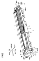
- Fig. 2 is a perspective view of a developing cartridge accommodated in the printer shown in Fig. 1 as viewed from a diagonally front left side;
- Fig. 3 is an exploded perspective view of the developing cartridge of Fig. 2 ;
- Fig. 4 is a left side view of a cartridge frame of the developing cartridge of Fig. 3 ;
- Fig. 5 is a left side view of the cartridge frame of Fig. 4 at which a gear train is disposed;
- Fig. 6 is a perspective view of an agitator gear of the developing cartridge of Fig. 3 as viewed from a left side;
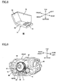
- Fig. 7 is a perspective view of a gear cover of the developing cartridge of Fig. 3 as viewed from a diagonally rear right side;
- Fig. 8 is a perspective view of a shutter of the developing cartridge of Fig. 3 as viewed from a diagonally rear right side;
- Fig. 9 is a view for description of relative positional relationship among the gear cover, the shutter, and the agitator gear;
- Figs. 10A and 10B are views for description of movement of the shutter; and in which Fig. 10A shows a state where the shutter is at a covered position, and Fig. 10B shows a state where the shutter is at the exposed position;
- Figs. 11A and 11B are views for description of a new cartridge detecting operation; and in which Fig. 11A shows a state where a detection unit is at a new cartridge detection position and the shutter is at the covered position, and Fig. 11B shows a state where the detection unit is at the new cartridge detection position and the shutter is at the exposed position;
- Figs. 12A and 12B are views for description of a cartridge type detecting operation; and in which Fig. 12A shows a state where the detection unit is at a cartridge type detection position and a right end portion of a probe is in abutment with an agitator gear, and Fig. 12B shows a state where the detection unit is at the cartridge type detection position and the right end portion of the probe is inside a detected opening formed in the agitator gear;
- Figs. 13A and 13B are views for description of detection by an empty sensor unit; and in which Fig. 13A shows a toner amount detection for a remaining amount of toner in a toner chamber, and Fig. 13B shows a position detection of an agitator;
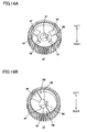
- Fig. 14A is a perspective view of an agitator gear according to one modification; in which the agitator gear is formed with two detected openings; and
- Fig. 14B is a perspective view of an agitator gear according to another modification; in which the agitator gear is provided with two detected protrusions.
- FIG. 1 A printer as an image forming apparatus according to one embodiment of the present invention will be described with reference to Figs. 1 through 13A .
- the terms “upward”, “downward”, “upper”, “lower”, “above”, “below”, “beneath”, “right”, “left”, “front”, “rear” and the like will be used assuming that the image forming apparatus is disposed in an orientation in which it is intended to be used. More specifically, in Fig. 1 a left side and a right side are a front side and a rear side, respectively.
- the printer 1 is a horizontal direct tandem type color printer.
- the printer 1 includes a main casing 2 having a generally box shape.
- the main casing 2 has an upper portion provided with a top cover 4 which can be opened or closed for opening and closing an opening 3.
- the top cover 4 has a rear end portion pivotally movably supported to the main casing 2.
- the printer 1 includes four process cartridges 5.
- Each process cartridge 5 is detachable from and attachable to the main casing 2. When mounted, the process cartridges 5 are juxtaposedly arrayed in the frontward/rearward direction at intervals within the main casing 2.
- the four process cartridges 5 corresponds to four colors different from each other (black, yellow, magenta, and cyan), respectively.
- Each process cartridge 5 includes a drum cartridge 6 and a developing cartridge 7 as a claimed cartridge detachable from and attachable to the drum cartridge 6.
- Each drum cartridge 6 has a photosensitive drum 8.
- the photosensitive drum 8 is cylindrical in shape and extends in a lateral direction (rightward/leftward direction), and is rotatably supported to a frame of the drum cartridge 6.
- the drum cartridge 6 has a scorotron charger 9 and an LED unit 10.
- the scorotron charger 9 is positioned diagonally above and rearward of the photosensitive drum 8, and confronts the photosensitive drum 8.
- the LED unit 10 is positioned above the photosensitive drum 8, and confronts the photosensitive drum 8.
- the developing cartridge 7 has a developing roller 11 and a supply roller 12 adapted to supply toner to the developing roller 11.
- the developing roller 11 has a rotation shaft extending in the lateral direction.
- the developing roller 11 is rotatably supported in a rear end portion of the developing cartridge 7 such that each lateral end portion of the rotation shaft is rotatably supported to each side wall 33 of a cartridge frame 31 ( Fig. 2 , described later) of the developing cartridge 7.
- a rear edge of the developing roller 11 is exposed to an outside through a rear edge of the developing cartridge 7 and contacts the corresponding photosensitive drum 8 from an upper front side thereof.
- the supply roller 12 has a rotation shaft extending in the lateral direction.
- the supply roller 12 is rotatably supported in the developing cartridge 7 such that each lateral end portion of the rotation shaft is rotatably supported to each side wall 33 of the cartridge frame 31 (described later).
- the supply roller 12 is disposed diagonally above and frontward of the developing roller 11 and in contact therewith.
- the developing cartridge 7 is provided with a layer thickness regulation blade 13, a toner chamber 14 and an agitator 15.
- the layer thickness regulation blade 13 is adapted to regulate a thickness of a toner layer supplied to the developing roller 11.
- the toner chamber 14 is positioned above the developing roller 11 and the supply roller 12.
- the toner chamber 14 accommodates toner as a developing agent therein.
- the agitator 15 as an agitation member is provided in the toner chamber 14 for agitating the toner.
- the agitator 15 includes an agitator shaft 16 extending in the lateral direction (i.e. a predetermined direction) and agitation blades 17 extending radially toward an inner circumferential surface of the toner chamber 14 from the agitator shaft 16.
- the agitator 15 is adapted to rotate about an axis A as a claimed rotation axis ( Fig. 3 ) of the agitator shaft 16. That is, the agitator 15 is an example of rotation body.
- Toner accommodated in the toner chamber 14 is subjected to triboelectric charging to have a positive polarity between the supply roller 12 and the developing roller 11.
- the toner is carried on an outer peripheral surface of the developing roller 11 in a form of a thin toner layer having a uniform thickness by the layer thickness regulation blade 13.
- an outer peripheral surface of the photosensitive drum 8 is uniformly charged by the scorotron charger 9, the surface is exposed to light by the LED unit 10 based on a predetermined image data to form an electrostatic latent image on the surface. Then, a visible toner image (developing agent image) corresponding to the electrostatic latent image is formed on the outer peripheral surface of the photosensitive drum 8 by supplying toner carried on the developing roller 11 to the corresponding photosensitive drum 8.
- a sheet cassette 18 is provided at a bottom portion of the main casing 2 for accommodating sheets P therein in a stacked state.
- Each sheet P accommodated in the sheet cassette 18 is passed through a U-shaped passage and is conveyed diagonally upward and rearward to a position between the photosensitive drum 8 and a conveyor belt 19 at a prescribed timing by various rollers. Then, each sheet P is conveyed rearward by the conveyer belt 19 at a position between each photosensitive drum 8 and each transfer roller 20. At this time, the toner image is transferred onto the sheet P.
- the sheet P onto which the toner image has been transferred is then conveyed to a fixing unit provided downstream of the conveyer belt 19.
- the fixing unit includes a heat roller 21 and a pressure roller 22.
- the toner image is thermally fixed to the sheet P when the sheet P passes through the heat roller 21 and the pressure roller 22.
- the sheet P carrying the toner image is then conveyed through an U-shaped passage frontward and upward, and is discharged onto a discharge tray 23 provided at the top cover 4.
- the developing cartridge 7 includes a cartridge frame 31 as a claimed frame and a drive unit 32 positioned at a left side of the cartridge frame 31.
- a side on which the developing roller 11 is disposed is defined as the rear side
- a side on which the layer thickness regulation blade 13 is disposed is defined as the upper side
- the cartridge frame 31 extends in the lateral direction and is generally box shaped, as shown in Figs. 2 and 3 .
- the cartridge frame 31 includes the pair of side walls 33, a front wall 34, a lower wall 35 and an upper wall 36.
- the pair of side walls 33 includes a left side wall 33L and a right side wall 33R.
- Each side wall 33 extends in the frontward/rearward direction and in the vertical direction, and is generally rectangular shaped in a side view.
- the pair of side walls 33 is spaced away from each other in the lateral direction.
- the left side wall 33L is formed with an agitator shaft exposure hole 37, and a detection window 38, as shown in Fig. 3 .
- the agitator shaft exposure hole 37 is formed for exposing the agitator shaft 16 to the outside therethrouh.
- the agitator shaft exposure hole 37 is positioned at a generally center portion of the left side wall 33L in the frontward/rearward direction and is generally circular shaped in a side view.
- the agitator shaft exposure hole 37 is penetrated through a thickness of the left side wall 33L and has a diameter greater than an outer diameter of a left end portion of the agitator shaft 16.
- the left end portion of the agitator shaft 16 extends through the agitator shaft exposure hole 37 and protrudes laterally outward from the left side wall 33L.
- the detection window 38 is formed in the left side wall 33L and positioned adjacent to the agitator shaft exposure hole 37. More specifically, the detection window 38 is positioned diagonally below and frontward of the agitator shaft exposure hole 37.
- the detection window 38 is a generally circular shaped in a side view. The detection window 38 is penetrated through a thickness of the left side wall 33L. The detection window 38 is closed by a transparent resin plate.
- the agitator shaft 16 has a right end portion which is rotatably supported to the right side wall 33R. Further, the right side wall 33R is formed with a detection window (not shown) similar to the detection window 38 formed in the left side wall 33L. The detection window of the right side wall 33R is superposed with the detection window 38 of the left side wall 33L when projected in the lateral direction.
- the front wall 34 extends in the lateral direction and is spanned between front end portions of the side walls 33.
- the lower wall 35 extends in the lateral direction and is spanned between lower end portions of the side walls 33 such that the lower wall 35 is connected to a lower end portion of the front wall 34.
- the upper wall 36 extends in the lateral direction and is spanned between upper end portions of the side walls 33 such that the upper wall 36 is connected to an upper end portion of the front wall 34.
- the drive unit 32 includes a gear train 41 as a claimed driving force transmission unit and a gear cover 42 for covering the gear train 41.
- the gear train 41 includes a developing gear 43, a supply gear 44, a developing coupling 45, an idle gear 46, and an agitator gear 47.
- the gear train 41 is adapted to transmit a driving force from the main casing 2 to the agitator 15.
- the developing gear 43 is assembled to a left side of the left side wall 33L of the cartridge frame 31.
- the developing gear 43 is fixedly coupled to a left end portion of the rotation shaft of the developing roller 11 protruding leftward from the left side wall 33L such that relative rotation therebetween is prevented.
- the supply gear 44 is assembled to the left side of the left side wall 33L of the cartridge frame 31.
- the supply gear 44 is fixedly coupled to a left end portion of the rotation shaft of the supply roller 12 protruding leftward from the left side wall 33L such that relative rotation therebetween is prevented.
- the supply gear 44 is positioned below and spaced apart from the developing gear 43.
- the developing coupling 45 is rotatably supported to the left side wall 33L of the cartridge frame 31 and positioned frontward of the developing gear 43.
- the developing coupling 45 is generally cylindrical shaped extending in the lateral direction.
- the developing coupling 45 integrally includes a large-diameter gear portion 48, a small-diameter gear portion 49, and a coupling portion 50.
- the large-diameter gear portion 48 is provided at a right end portion of the developing coupling 45. Gear teeth are provided along the entire circumferential surface of the large-diameter gear portion 48.
- the large-diameter gear portion 48 is meshingly engaged with the developing gear 43 from a front side thereof.
- the small-diameter gear portion 49 is generally cylindrical shaped extending leftward continuously from a left end portion of the large-diameter gear portion 48 and coaxial with the large-diameter gear portion 48.
- the small-diameter gear portion 49 has an outer diameter smaller than that of the large-diameter gear portion 48.
- Gear teeth are provided along the entire circumferential surface of the small-diameter gear portion 49.
- the small-diameter gear portion 49 is meshingly engaged with the supply gear 44 from an upper-front side thereof.
- the coupling portion 50 is generally cylindrical shaped extending leftward continuously from a left end portion of the small-diameter gear portion 49 and coaxial with the large-diameter gear portion 48.
- the coupling portion 50 has an outer diameter smaller than that of the small-diameter gear portion 49.
- the coupling portion 50 has a left side surface provided with a fitting portion 51.
- the idle gear 46 is rotatably supported to the left side wall 33L of the cartridge frame 31 at a front side of the developing coupling 45.
- the idle gear 46 is generally disk shaped having a thickness in the lateral direction.
- the idle gear 46 integrally includes a large-diameter portion 52 and a small-diameter portion 53.
- the large-diameter portion 52 constitutes a left half portion of the idle gear 46.
- the large-diameter portion 52 is generally disk shaped having gear teeth formed along the entire circumference thereof.
- the large-diameter portion 52 is meshingly engaged with the small-diameter gear portion 49 of the developing coupling 45 from a lower-front side thereof.
- the small-diameter portion 53 constitutes a right half portion of the idle gear 46 and is coaxial with the large-diameter portion 52.
- the small-diameter portion 53 is generally disk shaped having gear teeth formed along the entire circumference thereof.
- the small-diameter portion 53 is disposed diagonally below and frontward of the large-diameter gear portion 48 of the developing coupling 45 and spaced apart therefrom.
- the agitator gear 47 is fixedly coupled to a left end portion of the agitator shaft 16 protruding leftward from the left side wall 33L such that relative rotation therebetween is prevented.
- the agitator gear 47 is rotatably supported to the left side wall 33L of the cartridge frame 31 through the agitator shaft 16.
- the agitator gear 47 is meshingly engaged with the small-diameter portion 53 of the idle gear 46 from an upper front side thereof.
- the agitator gear 47 is formed with a fitting hole 54 in which the agitator shaft 16 is fitted and a detected opening 55 as a claimed detected portion.
- the fitting hole 54 is positioned at a radially substantially center portion of the agitator gear 47.
- the fitting hole 54 is generally D-shaped in a side view and penetrated through a thickness of the agitator gear 47 in the lateral direction.
- the left end portion of the agitator shaft 16 is generally D-shaped in correspondence with the shape of the fitting hole 54, and non-rotatably fitted into the fitting hole 54 so that relative rotation between the agitator gear 47 and the agitator shaft 16 is prevented.
- the detected opening 55 is positioned between the gear teeth of the agitator gear 47 and the fitting hole 54.
- the detected opening 55 is an opening penetrating a thickness of the agitator gear 47 in the lateral direction.
- the detected opening 55 has a generally arcuate shape extending in a circumferential direction of the agitator gear 47.
- the detected opening 55 is defined by an upstream surface 56 and a downstream surface 57.
- the upstream surface 56 is positioned upstream of the downstream surface 57 in a clockwise direction in a left side view.
- the upstream surface 56 is inclined diagonally rightward in a direction from an upstream end to a downstream end of the upstream surface 56 in the clockwise direction in a left side view.
- the downstream surface 57 is inclined diagonally leftward from an upstream end to a downstream end of the downstream surface 57 in the clockwise direction in a left side view.
- the gear cover 42 includes a main portion 61 and a shutter 62 as a claimed moving member.
- the main portion 61 is generally hollow prismatic body shaped and extends in the lateral direction with its leftmost end being closed.
- the main portion 61 includes a collar portion 63, a support portion 66, and a regulation portion 67. Further, the main portion 61 is formed with a detection opening 64 and an exposure opening 65.
- the collar portion 63 is positioned at a rear end portion of a left wall of the main portion 61 and protrudes leftward from the left wall of the main portion 61.
- the collar portion 63 is generally hollow cylindrical shaped with its right end portion being in communication with an internal space of the main portion 61.
- the coupling portion 50 of the developing coupling 45 extends through the collar portion 63 and is rotatable relative to the collar portion 63.
- the fitting portion 51 of the coupling portion 50 is exposed to the outside through a left end portion of the collar portion 63.
- the detection opening 64 is generally circular shaped in a side view.
- the detection opening 64 is positioned at a generally center portion of the left wall of the main portion 61 in the frontward/rearward direction such that the detection opening 64 confronts a lower front end portion of the agitator gear 47 from a left side thereof.
- the detection opening 64 is penetrated through a thickness of the left wall of the main portion 61.
- the exposure opening 65 is generally square shaped in a front view.
- the exposure opening 65 is positioned at a lower end portion of a front wall of the main portion 61.
- the exposure opening 65 is penetrated through a thickness of the front wall of the main portion 61.
- the support portion 66 is generally rectangular shaped in a side view and elongated in the frontward/rearward direction.
- the support portion 66 is disposed at a right surface side of the left wall of the main portion 61 and at a rear side of a lower end portion of the exposure opening 65.
- the support portion 66 protrudes upward from a lower wall of the main portion 61.
- the regulation portion 67 is a protrusion protruding rightward from the left wall of the main portion 61 and extending in the frontward/rearward direction.
- the regulation portion 67 is disposed at the right surface side of the left wall of the main portion 61 and at a rear side of an upper end portion of the exposure opening 65.
- the shutter 62 integrally includes a slider 71 as a claimed partially untoothed gear, a display portion 73, and a cover portion 72.
- the slider 71 is generally flat plate shaped extending in the frontward/rearward direction. Gear teeth are provided at an upper surface of a rear end portion of the slider 71. In the slider 71, a portion where gear teeth are provided will be referred to as a toothed portion 74, and a portion where gear teeth are not provided will be referred to as an untoothed portion 75.
- the display portion 73 is generally rectangular flat-plate shaped in a front view extending continuously from a front end portion of the slider 71 and inclined diagonally upward toward a front side of the display portion 73.
- the cover portion 72 is generally rectangular flat-plate shaped in a side view extending upward continuously from left end portions of the slider 71 and the display portion 73.
- the shutter 62 is slidably mounted on the support portion 66 of the main portion 61 such that the cover portion 72 is positioned between the support portion 66 and regulation portion 67.
- This configuration allows the shutter 62 to move to a covered position ( Fig. 10A ) and to an exposed position ( Fig. 10B ). At the covered position, the shutter 62 covers the lower front end portion of the agitator gear 47. At the exposed position, the shutter 62 allows the lower front end portion of the agitator gear 47 to be exposed to the outside.
- the cover portion 72 of the shutter 62 is interposed between the detection opening 64 and the lower front end portion of the agitator gear 47. Further, the display portion 73 of the shutter 62 is retracted rearward from the exposure opening 65 of the main portion 61. Further, the toothed portion 74 of the shutter 62 is meshingly engaged with a lower end portion of the agitator gear 47.
- the cover portion 72 of the shutter 62 is advanced frontward from a position between the detection window 64 and the lower front end portion of the agitator gear 47.
- the display portion 73 of the shutter 62 is exposed to the outside (a front side of the exposure opening 65) through the exposure opening 65 of the main portion 61.
- the toothed portion 74 of the shutter 62 is positioned frontward of the lower end portion of the agitator gear 47 and spaced apart therefrom.
- a detection unit 78 As shown in Figs. 2 , 11A , 11B , 12A, and 12B , a detection unit 78, an empty sensor unit 79, and a CPU 82 as a judgment unit are provided within the main casing 2.
- the detection unit 78 is positioned at a left side of the developing cartridge 7 within the main casing 2. As shown in Figs. 11A through 12B , the detection unit 78 includes a slide member 84, a probe 87, an actuator 88, and a photo-sensor 89.
- the slide member 84 is a generally rectangular flat plate shaped extending in the vertical direction.
- the slide member 84 is slidably movable in the lateral direction by a moving mechanism (not shown).
- the probe 87 is generally cylindrical shaped extending in the lateral direction.
- the probe 87 is movably supported in the slide member 84.
- the probe 87 is slidably movable in the lateral direction to an advanced position ( Figs. 11B and 12B ) and to a retracted position ( Figs. 11A and 12A ).
- the probe 87 is advanced rightward, and at the retracted position, the probe 87 is retracted leftward from the advanced position.
- the probe 87 is connected to a compression coil spring 86, so that the probe 87 is normally urged rightward by the compression coil spring 86 so as to be positioned at the advanced position.
- the actuator 88 integrally includes a pivot shaft 91, an abutment lever 92, and a light shielding lever 93.
- the pivot shaft 91 extends in the frontward/rearward direction and is generally hollow cylindrical shaped.
- the abutment lever 92 extends upward from the pivot shaft 91.
- the light shielding lever 93 extends downward from the pivot shaft 91.
- the light shielding lever 93 has a lower end portion provided with a light shielding plate 94 extending in the lateral direction.
- the actuator 88 is supported to the slide member 84 and pivotally movable relative to the slide member 84 about the pivot shaft 91.
- the actuator 88 is pivotally movable to a light transmitting position ( Figs. 11B and 12B ) and to a light shielding position ( Figs. 11A and 12A ).
- the abutment lever 92 is directed diagonally upward and rightward and the light shielding lever 93 is directed diagonally downward and leftward.
- the abutment lever 92 and the light shielding lever 93 are directed in the vertical direction.
- the photo-sensor 89 includes a light emitting portion 95 and a light receiving portion 96.
- the light emitting portion 95 is adapted to emit a light.
- the light receiving portion 96 is adapted to receive the light from the light emitting portion 95 and positioned in confrontation with and downward of the light emitting portion 95 with a gap therebetween.
- the photo-sensor 89 is positioned below the actuator 88 such that the light shielding plate 94 of the actuator 88 at the light shielding position is positioned between the light emitting portion 95 and the light receiving portion 96 in the vertical direction.
- the light shielding plate 94 of the actuator 88 is positioned between the light emitting portion 95 and the light receiving portion 96, so that the light emitted from the light emitting portion 95 of the photo-sensor 89 is blocked by the light shielding plate 94 of the light shielding lever 93, whereupon an ON signal is outputted from the photo-sensor 89.
- the light shielding plate 94 of the actuator 88 is retracted leftward from the gap between the light emitting portion 95 and the light receiving portion 96.
- the light emitted from the light emitting portion 95 of the photo-sensor 89 is received by the light receiving portion 96.
- an ON signal is not outputted from the photo-sensor 89.
- the detection unit 78 is movable within the main casing 2 to a new cartridge detection position ( Figs. 11A and 11B ) and to a cartridge type detection position ( Figs. 12A and 12B ). At the new cartridge detection position, the detection unit 78 detects whether the developing cartridge 7 is new or used. At the cartridge type detection position, the detection unit 78 detects types of the developing cartridge 7.
- the empty sensor unit 79 includes a light emitting element 80 and a light receiving element 81.
- the light emitting element 80 is positioned within the main casing 2 and in confrontation with the detection opening 64 of the gear cover 42 from a left side thereof.
- the light emitting element 80 is adapted to emit a detection light to the detection opening 64.
- the light receiving element 81 is positioned within the main casing 2 and in confrontation with the detection window (not shown) of the right side wall 33R of the cartridge frame 31 from a right side thereof.
- the light receiving element 81 outputs an ON signal upon receipt of the detection light emitted from the light emitting element 80.
- a combination of the detection unit 78 and the empty sensor unit 79 constitutes a claimed detection unit.
- the CPU 82 is electrically connected to the photo-sensor 89 and the light receiving element 81 so as to receive the ON signal from the photo-sensor 89 and the ON signal from the light receiving element 81.
- the unused developing cartridge 7 is first attached to the drum cartridge 6.
- the developing cartridge 7 is unused in a case where the display portion 73 of the shutter 62 is not exposed to the outside through the exposure opening 65, while the developing cartridge 7 is in a used state in a case where the display portion 73 of the shutter 62 is exposed to the outside through the exposure opening 65.
- the user may determine a used or unused state of the developing cartridge 7 by looking at the shutter 62 as to whether the shutter 62 is visible or invisible through the detection opening 64.
- the top cover 4 of the main casing 2 is opened to insert, from diagonally above and frontward thereof, into the main casing 2 the process cartridge 5 to which the unused developing cartridge 7 is assembled.
- the top cover 4 is closed.
- the main coupling (not shown) provided in the main casing 2 is coupled to the developing coupling 45, preventing relative rotation therebetween.
- the detection unit 78 is positioned at the new cartridge detection position before the main coupling (not shown) is driven.
- a right end portion of the probe 87 is brought into contact with the cover portion 72 of the shutter 62 from a left side thereof through the detection opening 64 of the main portion 61.
- the probe 87 is pressed leftward against the urging force of the compression coil spring 86 to be positioned at the retracted position.
- the actuator 88 is pivotally moved in the counterclockwise direction in a front view to be positioned at the light shielding position
- the photo-sensor 89 outputs the ON signal to the CPU 82. That is, the detection unit 78 detects the covered position of the shutter 62.
- the CPU 82 determines that the shutter 62 has been positioned at the covered position upon receipt of the ON signal from the photo-sensor 89 in a state where the detection unit 78 is at the new cartridge detection position.
- a driving force from the main casing 2 is transmitted to the developing coupling 45 through the main coupling (not shown) for starting a warm-up operation.
- a driving force from the developing coupling 45 is transmitted to the agitator gear 47 through the gear train 41.
- the agitator 15 is rotated in the counterclockwise direction in a left side view.
- the cover portion 72 of the shutter 62 is retracted frontward from a position between the detection opening 64 and the lower front end portion of the agitator gear 47, and the probe 87 is pressed rightward by the urging force of the compression coil spring 86 to be positioned at the advanced position.
- the actuator 88 is pivotally moved in the clockwise direction in a front view from the light shielding position to the light transmitting position.
- the CPU 82 determines that the shutter 62 has been moved from the covered position to the exposed position due to interruption of the ON signal from the photo-sensor 89.
- the CPU 82 determines that the developing cartridge 7 is unused.
- the CPU 82 determines that the developing cartridge 7 is an unused cartridge when the detection unit 78 detects a movement of the shutter 62 from the covered position to the exposed position within a predetermined time period.
- the detection unit 78 is moved rightward to be positioned at the cartridge type detection position while the agitator gear 47 is rotated continuously.
- the probe 87 is pressed leftward against the urging force of the compression coil spring 86 to be positioned at the retracted position.
- the actuator 88 is pivotally moved in the counterclockwise direction in a front view to be positioned at the light shielding position.
- the photo-sensor 89 outputs the ON signal to the CPU 82.
- the CPU 82 determines that the probe 87 has been moved from the advanced position to the retracted position upon receipt of the ON signal from the photo-sensor 89.
- the probe 87 is pressed rightward by the urging force of the compression coil spring 86 to be positioned at the advanced position.
- the actuator 88 is pivotally moved in the clockwise direction in a front view from the light shielding position to be positioned at the light transmitting position.
- the CPU 82 determines that the detected opening 55 of the agitator gear 47 has been detected due to interruption of the ON signal from the photo-sensor 89 in a state where the detection unit 78 is at the cartridge type detection position.
- the CPU 82 determines the type of the developing cartridge 7 in accordance with the number of times of interruption of the ON signal from the photo-sensor 89 per unit time.
- the ON signal from the photo-sensor 89 is interrupted once during one rotation of the agitator 15.
- the CPU 82 determines that a predetermined printing times is 6,000 sheets printing.
- the ON signal from the photo-sensor 89 is interrupted twice during one rotation of the agitator 15.
- the CPU 82 determines that a predetermined printing times is 3,000 sheets printing.
- the number of the detected openings 55 corresponds to information about the types of the developing cartridge 7. More specifically, the case where the agitator gear 47 is formed with a single detected opening 55 corresponds to information (first information) about the types of the developing cartridge 7 indicating that the predetermined printing times is 6,000 sheets printing, and the case where the agitator gear 47 is formed with two detected openings 55 corresponds to information (second information) about the types of the developing cartridge 7 indicating that the predetermined printing times is 3,000 sheets printing.
- the CPU 82 counts actual printing times starting from assembly of the unused developing cartridge 7 into the main casing 2, and notifies and displays on an operation panel (not shown) an exchanging timing of the developing cartridge 7 when the counted printing times approaches a predetermined printing times in accordance with the types of the developing cartridge 7.
- the CPU 82 determines that the developing cartridge 7 has been detached from the main casing 2 when the type of the developing cartridge 7 has not been detected within a predetermined period of time.
- the developing cartridge 7 is again assembled to the main casing 2 after the developing cartridge 7 is detached from the main casing 2, for example, for removing a jammed sheet P.
- the shutter 62 is stopped at the exposed position.
- the user looks at the gear cover 42 of the developing cartridge 7 to confirm that the display portion 73 of the shutter 62 is exposed to the outside through the exposure opening 65.
- the user determines that the developing cartridge 7 is an old cartridge (a cartridge in use).
- the probe 87 is not positioned at the retracted position but stays at the advanced position as shown in Fig. 11B when the detection unit 78 is positioned at the new cartridge detection position. Thus, the CPU 82 does not receive the ON signal from the photo-sensor 89.
- the CPU 82 determines that the shutter 62 has stayed at the exposed position. Further, the CPU 82 determines that the re-assembled cartridge 7 is an old cartridge.
- the CPU 82 continues comparison between the predetermined printing times and the accumulated total number of printing times from the timing at which the CPU 82 determines that the assembled developing cartridge 7 is a new cartridge.
- the detection unit 78 is retracted from an optical path of the detection light emitted from the light emitting element 80.
- the detected opening 55 and the detection window 38 are opposed to each other by rotation of the agitator gear 47 as shown in Fig. 13A , the detection light enters the toner chamber 14 passing through the detection window 38. That is, the detected opening 55 serves also as a light guiding portion that guides the detection light to the toner chamber 14.
- the light receiving element 81 When an amount of the toner in the toner chamber 14 is reduced to allow the detection light to pass through the toner chamber 14 and the detection window (not shown) of the right side wall 33R of the cartridge frame 31, and thus, the detection light is received by the light receiving element 81, the light receiving element 81 outputs an ON signal to the CPU 82.
- the CPU 82 determines that the amount of the toner in the toner chamber 14 is reduced.
- the CPU 82 notifies and displays on an operation panel (not shown) that an exchanging timing of the developing cartridge 7 is approaching.
- the shutter 62 is irreversibly movable from the covered position ( Fig. 10A ) to the exposed position ( Fig. 10B ).
- the CPU 82 determines that the developing cartridge 7 is unused.
- the movement of the shutter 62 allows the detection unit 78 of the main casing 2 to detect the information as to whether the developing cartridge 7 is used or unused.
- the user can easily visually confirm a position of the display portion 73 of the shutter 62.
- the user can easily recognize whether the developing cartridge 7 is used or unused by confirming displacement of the display portion 73 of the shutter 62.
- the developing cartridge 7 can be determined to be unused when the display portion 73 of the shutter 62 is positioned at the exposed position.
- the agitator gear 47 can be covered by the shutter 62 before the driving force is inputted to the gear train 41, i.e., when the developing cartridge 7 is unused, as shown in Fig. 10A .
- the agitator gear 47 can be protected.
- the detection unit 78 can detect the types of the developing cartridge 7 at an arbitrary timing.
- the detected opening 55 serves also as a light guiding portion for guiding the detection light emitted from the light emitting element 80 of the empty sensor unit 79 to the toner chamber 14 as shown in Fig. 13A .
- the empty sensor unit 79 can detect the remaining amount of toner in the toner chamber 14.
- the remaining amount of toner in the toner chamber 14 is detected by means of the empty sensor unit 79.
- a position of the agitation blades 17 of the agitator 15 can be determined by means of the empty sensor unit 79. In this case, it is assumed that a toner level is below the detection window 38 and the detection light emitted from the light emitting element 80 is always received by the light receiving element 81.
- the CPU 82 determines that the agitation blades 17 are in confrontation with the detection window 38 due to interruption of the ON signal from the light receiving element 81.
- the position of the agitation blades 17 of the agitator 15 can be detected by means of the empty sensor unit 79.
- rotation of the agitator 15 can be controlled so as to stop the agitation blades 17 at a desired position.
- the empty sensor unit 79 includes the light emitting element 80 and the light receiving element 81.
- the light emitting element 80 is positioned at a left side of the developing cartridge 7, and the light receiving element 81 is positioned at a right side of the developing cartridge 7.
- the detection light from the light emitting element 80 is received by the light receiving element 81.
- both the light emitting element 80 and the light receiving element 81 are positioned at a left side of the developing cartridge 7 and a reflection plate is positioned at a right side of the developing cartridge 7 to allow the detection light from the light emitting element 80 to be reflected by the reflection plate and received by the light receiving element 81.
- the shutter 62 is positioned at the covered position in a state where the developing cartridge 7 is unused, and the shutter 62 is moved from the covered position to the exposed position in the new cartridge detection operation.
- a configuration may be possible in which the shutter 62 is positioned at the exposed position in a state where the developing cartridge 7 is unused and the shutter 62 is moved from the exposed position to the covered position in the new cartridge detection operation.
- the toothed portion 74 of the shutter 62 is moved rearward of the agitator gear 47 so as to be spaced away from the agitator gear 47, and the untoothed portion 75 of the shutter 62 is opposed to the agitator gear 47 from below.
- the cartridge type detecting operation and the toner amount detecting operation may be performed by methods different from those described in the above embodiment and known to those skilled in the art.
- the agitator gear 47 can be covered after input of the driving force to the gear train 41, i.e., while the developing cartridge 7 is being used.
- the agitator 47 can be protected while the developing cartridge 7 is being used.
- the shutter 62 includes the toothed portion 74 to which the driving force is transmitted and the untoothed portion 75 to which the driving force is not transmitted. Accordingly, the shutter 62 can be stopped reliably after being moved with a predetermined moving amount.
- the shutter 62 can reliably be irreversibly moved with a simple configuration.
- the number of the detected openings 55 formed in the agitator gear 47 corresponds to information about the type of the developing cartridge 7. Further, the CPU 82 determines the type of the developing cartridge 7 in accordance with the number of times of interruption of the ON signal from the photo-sensor 89 per unit time.
- a length of the detected opening 55 in a circumferential direction of the agitator gear 47 may be made to correspond to the information about the type of the developing cartridge 7.
- this length of the detected opening 55 corresponds to the information (first information) about the type of the developing cartridge 7 indicating that a predetermined printing times is 6,000 sheets printing. Further, in a case where the length of the detected opening 55 in the circumferential direction of the agitator 47 is short, this length of the detected opening 55 corresponds to the information (second information) about the type of the developing cartridge 7 indicating that a predetermined printing times 3,000 sheets printing.
- the CPU 82 determines the types of the developing cartridge 7 in accordance with duration of interruption of the ON signal from the photo-sensor 89.
- the CPU 82 determines that the predetermined printing times is 6,000 sheets printing. Further, in a case where the duration of interruption of the ON signal from the photo-sensor 89 is short, the CPU 82 determines that the predetermined printing times is 3,000 sheets printing.
- the detected opening 55 as a detected portion is formed in the agitator gear 47.
- a shape of the detected portion is not specifically limited.
- two detected projections 100 may be provided in the agitator gear 47 as an example of two detected portions.
- Each of the detected projections 100 is formed as a projection protruding leftward from a left surface of the agitator gear 47.
- the detected projection 100 is defined by a first sloped surface 98 and a second sloped surface 99.
- the first sloped surface 98 is positioned downstream of the second sloped surface 99 in the clockwise direction in a left side view.
- the first sloped surface 98 is inclined diagonally rightward from an upstream end to a downstream end of the first sloped surface 98 in the clockwise direction in a left side view.
- the second sloped surface 99 is inclined diagonally leftward from an upstream end to a downstream end of the second sloped surface 99 in the clockwise direction in a left side view.
- the toner amount detecting operation may be performed by a method different from that described in the above embodiment and known to those skilled in the art.
- the detection unit 78 is allowed to detect the types of the developing cartridge 7 with a simple configuration.
- the detection unit 78 is movable to the new cartridge detection position and to the cartridge type detection position.
- appropriate arrangement of the slide member 84, the probe 87, the actuator 88, and the photo-sensor 89 allows detection of whether the developing cartridge 7 is used or unused and detection of the type of the developing cartridge 7 without moving the detection unit 78.
Abstract
Description
- The present invention relates to a cartridge to be used in an electro-photographic type image forming apparatus, and to an image forming apparatus provided with the cartridge.
- As an electro-photographic type image forming apparatus, a printer including a photosensitive body and a developing cartridge configured to supply toner to the photosensitive body is known.
- A conventional printer is provided with a detection device for detecting information of the developing cartridge assembled therein, for example, for detecting whether or not the assembled developing cartridge is a brand new cartridge.
- Japanese Patent Application Publication No.
2006-267994 - In the above laser printer, the detection gear has an abutment protrusion corresponding to the information on the developing cartridge. The detection gear is rotated by a predetermined driving amount after assembly of the developing cartridge to the main casing. At this time, the abutment protrusion abuts on the actuator, allowing the rotation of the detection gear to be detected by the actuator.
- However, in the laser printer described above, the developing cartridge only has the detection gear for allowing the main casing to detect the information on the developing cartridge.
- Additionally, substantially the entire part of the detection gear is covered by a gear cover, which lowers visibility of the detection gear from outside the apparatus.
- Therefore, a user who does not have knowledge of the new cartridge detection device has a difficulty in determining whether the developing cartridge is a new one or a used one.
- It is therefore an object of the present invention to provide a cartridge allowing a user to easily determine whether the cartridge is unused or used and an image forming apparatus provided with the cartridge.
- In order to attain the above and other objects, the present invention provides a cartridge including: a frame; a rotation body; a driving force transmission unit; and a moving member. The frame is configured to accommodate therein developing agent. The rotation body has a rotation axis extending in a predetermined direction. The rotation body is provided at the frame and rotatable about the rotation axis relative to the frame. The driving force transmission unit is provided at the frame and configured to transmit an external driving force to the rotation body. The moving member is configured to be irreversibly moved to one of a covered position and an exposed position by the external driving force transmitted through the driving force transmission unit. The moving member covers at least a portion of the driving force transmission unit when the moving member is at the covered position. The moving member exposes the driving force transmission unit when the moving member is at the exposed position. The exposed position provides an exposing degree greater than that at the covered position.
- When the moving member is at the covered position, there may be no exposing degree. In other words, when the moving member is at the covered position, the moving member may cover the driving force transmission unit in its entirety.
- It is preferable that one of the covered position and the exposed position indicates that the cartridge is a new cartridge.
- It is preferable that the moving member is irreversibly moved from the covered position to the exposed position.
- It is preferable that the moving member is irreversibly moved from the exposed position to the covered position.
- It is preferable that the driving force transmission unit includes a detected portion configured to be detected by an external detection unit. The detected portion has information relating to types of the cartridge. The moving member covers the detected portion when the moving member is at the covered position.
- It is preferable that the detected portion is a projection detected by the external detection unit. The projection is indicative of one of the types of the cartridge.
- It is preferable that the detected portion includes a light guiding portion configured to guide a detection light emitted from the external detection unit into the frame.
- It is preferable that the rotation body is an agitation member configured to agitate developing agent.
- It is preferable that the moving member includes a partially untoothed gear comprising a toothed portion to which the external driving force is transmittable, and an untoothed portion prohibiting transmission of the external driving force.
- According to another aspect, the present invention provides an image forming apparatus including: a main casing; and the above-described cartridge. The cartridge is detachable from and attachable to the main casing. The external driving force is transmitted from the main casing. The main casing includes: a detection unit; and a judgment unit. The detection unit is configured to detect a movement of the moving member. The judgment unit is configured to judge a condition of the cartridge based on a detection of the detection unit.
- The condition of the cartridge judged by the judgment unit in the present invention implies a usage state of the cartridge whether the cartridge is new or used, types of the cartridge, a remaining amount of toner accommodated in the cartridge, and a position of agitation blades, for example.
- Further, when the moving member is at the covered position, there may be no exposing degree. That is, when the moving member is at the covered position, the moving member may cover the driving force transmission unit in its entirety.
- It is preferable that one of the covered position and the exposed position indicates that the cartridge is a new cartridge.
- It is preferable that the moving member is irreversibly moved from the covered position to the exposed position.
- It is preferable that the moving member is irreversibly moved from the exposed position to the covered position.
- It is preferable that the judgment unit makes a judgment that the cartridge attached to the main casing is a new cartridge if the detection unit detects the movement of the moving member within a predetermined period of time.
- It is preferable that the driving force transmission unit includes a detected portion configured to be detected by the detection unit. The detected portion has information relating to types of the cartridge. The moving member covers the detected portion at the covered position.
- It is preferable that the detected portion is a projection detected by the detection unit. The projection is indicative of one of the types of the cartridge.
- It is preferable that the detection unit is configured to emit a detection light. The detected portion includes a light guiding portion configured to guide the detection light into the frame.
- It is preferable that the rotation body is an agitation member configured to agitate developing agent.
- It is preferable that the moving member includes a partially untoothed gear including a toothed portion to which the driving force is transmittable, and an untoothed portion prohibiting transmission of the driving force.
- In the drawings;
-
Fig. 1 is a cross-sectional view of a printer according to one embodiment of the present invention; -
Fig. 2 is a perspective view of a developing cartridge accommodated in the printer shown inFig. 1 as viewed from a diagonally front left side; -
Fig. 3 is an exploded perspective view of the developing cartridge ofFig. 2 ; -
Fig. 4 is a left side view of a cartridge frame of the developing cartridge ofFig. 3 ; -
Fig. 5 is a left side view of the cartridge frame ofFig. 4 at which a gear train is disposed; -
Fig. 6 is a perspective view of an agitator gear of the developing cartridge ofFig. 3 as viewed from a left side; -
Fig. 7 is a perspective view of a gear cover of the developing cartridge ofFig. 3 as viewed from a diagonally rear right side; -
Fig. 8 is a perspective view of a shutter of the developing cartridge ofFig. 3 as viewed from a diagonally rear right side; -
Fig. 9 is a view for description of relative positional relationship among the gear cover, the shutter, and the agitator gear; -
Figs. 10A and 10B are views for description of movement of the shutter; and in whichFig. 10A shows a state where the shutter is at a covered position, andFig. 10B shows a state where the shutter is at the exposed position; -
Figs. 11A and 11B are views for description of a new cartridge detecting operation; and in whichFig. 11A shows a state where a detection unit is at a new cartridge detection position and the shutter is at the covered position, andFig. 11B shows a state where the detection unit is at the new cartridge detection position and the shutter is at the exposed position; -
Figs. 12A and 12B are views for description of a cartridge type detecting operation; and in whichFig. 12A shows a state where the detection unit is at a cartridge type detection position and a right end portion of a probe is in abutment with an agitator gear, andFig. 12B shows a state where the detection unit is at the cartridge type detection position and the right end portion of the probe is inside a detected opening formed in the agitator gear; -
Figs. 13A and 13B are views for description of detection by an empty sensor unit; and in whichFig. 13A shows a toner amount detection for a remaining amount of toner in a toner chamber, andFig. 13B shows a position detection of an agitator; -
Fig. 14A is a perspective view of an agitator gear according to one modification; in which the agitator gear is formed with two detected openings; and -
Fig. 14B is a perspective view of an agitator gear according to another modification; in which the agitator gear is provided with two detected protrusions. - A printer as an image forming apparatus according to one embodiment of the present invention will be described with reference to
Figs. 1 through 13A . Throughout the specification, the terms "upward", "downward", "upper", "lower", "above", "below", "beneath", "right", "left", "front", "rear" and the like will be used assuming that the image forming apparatus is disposed in an orientation in which it is intended to be used. More specifically, inFig. 1 a left side and a right side are a front side and a rear side, respectively. - 1. Overall Structure of Color Printer
- Referring to
Fig. 1 , theprinter 1 is a horizontal direct tandem type color printer. Theprinter 1 includes amain casing 2 having a generally box shape. Themain casing 2 has an upper portion provided with a top cover 4 which can be opened or closed for opening and closing an opening 3. The top cover 4 has a rear end portion pivotally movably supported to themain casing 2. Theprinter 1 includes fourprocess cartridges 5. - Each
process cartridge 5 is detachable from and attachable to themain casing 2. When mounted, theprocess cartridges 5 are juxtaposedly arrayed in the frontward/rearward direction at intervals within themain casing 2. The fourprocess cartridges 5 corresponds to four colors different from each other (black, yellow, magenta, and cyan), respectively. - Each
process cartridge 5 includes adrum cartridge 6 and a developingcartridge 7 as a claimed cartridge detachable from and attachable to thedrum cartridge 6. - Each
drum cartridge 6 has aphotosensitive drum 8. Thephotosensitive drum 8 is cylindrical in shape and extends in a lateral direction (rightward/leftward direction), and is rotatably supported to a frame of thedrum cartridge 6. - Further, the
drum cartridge 6 has a scorotron charger 9 and anLED unit 10. The scorotron charger 9 is positioned diagonally above and rearward of thephotosensitive drum 8, and confronts thephotosensitive drum 8. TheLED unit 10 is positioned above thephotosensitive drum 8, and confronts thephotosensitive drum 8. - The developing
cartridge 7 has a developingroller 11 and asupply roller 12 adapted to supply toner to the developingroller 11. - The developing
roller 11 has a rotation shaft extending in the lateral direction. The developingroller 11 is rotatably supported in a rear end portion of the developingcartridge 7 such that each lateral end portion of the rotation shaft is rotatably supported to eachside wall 33 of a cartridge frame 31 (Fig. 2 , described later) of the developingcartridge 7. A rear edge of the developingroller 11 is exposed to an outside through a rear edge of the developingcartridge 7 and contacts the correspondingphotosensitive drum 8 from an upper front side thereof. - The
supply roller 12 has a rotation shaft extending in the lateral direction. Thesupply roller 12 is rotatably supported in the developingcartridge 7 such that each lateral end portion of the rotation shaft is rotatably supported to eachside wall 33 of the cartridge frame 31 (described later). Thesupply roller 12 is disposed diagonally above and frontward of the developingroller 11 and in contact therewith. - The developing
cartridge 7 is provided with a layerthickness regulation blade 13, atoner chamber 14 and anagitator 15. The layerthickness regulation blade 13 is adapted to regulate a thickness of a toner layer supplied to the developingroller 11. Thetoner chamber 14 is positioned above the developingroller 11 and thesupply roller 12. Thetoner chamber 14 accommodates toner as a developing agent therein. - The
agitator 15 as an agitation member is provided in thetoner chamber 14 for agitating the toner. Theagitator 15 includes anagitator shaft 16 extending in the lateral direction (i.e. a predetermined direction) andagitation blades 17 extending radially toward an inner circumferential surface of thetoner chamber 14 from theagitator shaft 16. Theagitator 15 is adapted to rotate about an axis A as a claimed rotation axis (Fig. 3 ) of theagitator shaft 16. That is, theagitator 15 is an example of rotation body. - Toner accommodated in the
toner chamber 14 is subjected to triboelectric charging to have a positive polarity between thesupply roller 12 and the developingroller 11. The toner is carried on an outer peripheral surface of the developingroller 11 in a form of a thin toner layer having a uniform thickness by the layerthickness regulation blade 13. - After an outer peripheral surface of the
photosensitive drum 8 is uniformly charged by the scorotron charger 9, the surface is exposed to light by theLED unit 10 based on a predetermined image data to form an electrostatic latent image on the surface. Then, a visible toner image (developing agent image) corresponding to the electrostatic latent image is formed on the outer peripheral surface of thephotosensitive drum 8 by supplying toner carried on the developingroller 11 to the correspondingphotosensitive drum 8. - A
sheet cassette 18 is provided at a bottom portion of themain casing 2 for accommodating sheets P therein in a stacked state. Each sheet P accommodated in thesheet cassette 18 is passed through a U-shaped passage and is conveyed diagonally upward and rearward to a position between thephotosensitive drum 8 and aconveyor belt 19 at a prescribed timing by various rollers. Then, each sheet P is conveyed rearward by theconveyer belt 19 at a position between eachphotosensitive drum 8 and eachtransfer roller 20. At this time, the toner image is transferred onto the sheet P. - The sheet P onto which the toner image has been transferred is then conveyed to a fixing unit provided downstream of the
conveyer belt 19. The fixing unit includes aheat roller 21 and apressure roller 22. The toner image is thermally fixed to the sheet P when the sheet P passes through theheat roller 21 and thepressure roller 22. The sheet P carrying the toner image is then conveyed through an U-shaped passage frontward and upward, and is discharged onto adischarge tray 23 provided at the top cover 4. - 2. Details of Developing Cartridge
- As shown in
Figs. 2 and3 , the developingcartridge 7 includes acartridge frame 31 as a claimed frame and adrive unit 32 positioned at a left side of thecartridge frame 31. - When referring to the directions in the description of the developing
cartridge 7, the terms "upward", "downward", "upper", "lower", "above", "below", "beneath", "right", "left", "front", "rear" and the like will be used assuming that the developingcartridge 7 is detached from themain casing 2 and placed on a horizontal plane. Specifically, a side on which the developingroller 11 is disposed is defined as the rear side, and a side on which the layerthickness regulation blade 13 is disposed is defined as the upper side. - (1) Cartridge Frame
- The
cartridge frame 31 extends in the lateral direction and is generally box shaped, as shown inFigs. 2 and3 . Thecartridge frame 31 includes the pair ofside walls 33, afront wall 34, alower wall 35 and anupper wall 36. The pair ofside walls 33 includes aleft side wall 33L and aright side wall 33R. - Each
side wall 33 extends in the frontward/rearward direction and in the vertical direction, and is generally rectangular shaped in a side view. The pair ofside walls 33 is spaced away from each other in the lateral direction. Theleft side wall 33L is formed with an agitatorshaft exposure hole 37, and adetection window 38, as shown inFig. 3 . - The agitator
shaft exposure hole 37 is formed for exposing theagitator shaft 16 to the outside therethrouh. The agitatorshaft exposure hole 37 is positioned at a generally center portion of theleft side wall 33L in the frontward/rearward direction and is generally circular shaped in a side view. The agitatorshaft exposure hole 37 is penetrated through a thickness of theleft side wall 33L and has a diameter greater than an outer diameter of a left end portion of theagitator shaft 16. The left end portion of theagitator shaft 16 extends through the agitatorshaft exposure hole 37 and protrudes laterally outward from theleft side wall 33L. - The
detection window 38 is formed in theleft side wall 33L and positioned adjacent to the agitatorshaft exposure hole 37. More specifically, thedetection window 38 is positioned diagonally below and frontward of the agitatorshaft exposure hole 37. Thedetection window 38 is a generally circular shaped in a side view. Thedetection window 38 is penetrated through a thickness of theleft side wall 33L. Thedetection window 38 is closed by a transparent resin plate. - The
agitator shaft 16 has a right end portion which is rotatably supported to theright side wall 33R. Further, theright side wall 33R is formed with a detection window (not shown) similar to thedetection window 38 formed in theleft side wall 33L. The detection window of theright side wall 33R is superposed with thedetection window 38 of theleft side wall 33L when projected in the lateral direction. - The
front wall 34 extends in the lateral direction and is spanned between front end portions of theside walls 33. Thelower wall 35 extends in the lateral direction and is spanned between lower end portions of theside walls 33 such that thelower wall 35 is connected to a lower end portion of thefront wall 34. Theupper wall 36 extends in the lateral direction and is spanned between upper end portions of theside walls 33 such that theupper wall 36 is connected to an upper end portion of thefront wall 34. - (2) Drive Unit
- As shown in
Figs. 3 and5 , thedrive unit 32 includes agear train 41 as a claimed driving force transmission unit and agear cover 42 for covering thegear train 41. - (2-1) Gear Train
- The
gear train 41 includes a developinggear 43, asupply gear 44, a developingcoupling 45, anidle gear 46, and anagitator gear 47. Thegear train 41 is adapted to transmit a driving force from themain casing 2 to theagitator 15. - The developing
gear 43 is assembled to a left side of theleft side wall 33L of thecartridge frame 31. The developinggear 43 is fixedly coupled to a left end portion of the rotation shaft of the developingroller 11 protruding leftward from theleft side wall 33L such that relative rotation therebetween is prevented. - The
supply gear 44 is assembled to the left side of theleft side wall 33L of thecartridge frame 31. Thesupply gear 44 is fixedly coupled to a left end portion of the rotation shaft of thesupply roller 12 protruding leftward from theleft side wall 33L such that relative rotation therebetween is prevented. Thesupply gear 44 is positioned below and spaced apart from the developinggear 43. - The developing
coupling 45 is rotatably supported to theleft side wall 33L of thecartridge frame 31 and positioned frontward of the developinggear 43. The developingcoupling 45 is generally cylindrical shaped extending in the lateral direction. The developingcoupling 45 integrally includes a large-diameter gear portion 48, a small-diameter gear portion 49, and acoupling portion 50. - The large-
diameter gear portion 48 is provided at a right end portion of the developingcoupling 45. Gear teeth are provided along the entire circumferential surface of the large-diameter gear portion 48. The large-diameter gear portion 48 is meshingly engaged with the developinggear 43 from a front side thereof. - The small-
diameter gear portion 49 is generally cylindrical shaped extending leftward continuously from a left end portion of the large-diameter gear portion 48 and coaxial with the large-diameter gear portion 48. The small-diameter gear portion 49 has an outer diameter smaller than that of the large-diameter gear portion 48. Gear teeth are provided along the entire circumferential surface of the small-diameter gear portion 49. The small-diameter gear portion 49 is meshingly engaged with thesupply gear 44 from an upper-front side thereof. - The
coupling portion 50 is generally cylindrical shaped extending leftward continuously from a left end portion of the small-diameter gear portion 49 and coaxial with the large-diameter gear portion 48. Thecoupling portion 50 has an outer diameter smaller than that of the small-diameter gear portion 49. Thecoupling portion 50 has a left side surface provided with afitting portion 51. In a state where the developingcartridge 7 is assembled to themain casing 2, a leading end portion of a main coupling (not shown) provided to themain casing 2 is fixedly coupled to thefitting portion 51 such that relative rotation therebetween is prevented. A driving force from themain casing 2 is transmitted to thefitting portion 51 through the main coupling (not shown). - The
idle gear 46 is rotatably supported to theleft side wall 33L of thecartridge frame 31 at a front side of the developingcoupling 45. Theidle gear 46 is generally disk shaped having a thickness in the lateral direction. Theidle gear 46 integrally includes a large-diameter portion 52 and a small-diameter portion 53. - The large-
diameter portion 52 constitutes a left half portion of theidle gear 46. The large-diameter portion 52 is generally disk shaped having gear teeth formed along the entire circumference thereof. The large-diameter portion 52 is meshingly engaged with the small-diameter gear portion 49 of the developingcoupling 45 from a lower-front side thereof. - The small-
diameter portion 53 constitutes a right half portion of theidle gear 46 and is coaxial with the large-diameter portion 52. The small-diameter portion 53 is generally disk shaped having gear teeth formed along the entire circumference thereof. The small-diameter portion 53 is disposed diagonally below and frontward of the large-diameter gear portion 48 of the developingcoupling 45 and spaced apart therefrom. - The
agitator gear 47 is fixedly coupled to a left end portion of theagitator shaft 16 protruding leftward from theleft side wall 33L such that relative rotation therebetween is prevented. Theagitator gear 47 is rotatably supported to theleft side wall 33L of thecartridge frame 31 through theagitator shaft 16. Theagitator gear 47 is meshingly engaged with the small-diameter portion 53 of theidle gear 46 from an upper front side thereof. - More specifically, as illustrated in
Fig. 6 , theagitator gear 47 is formed with afitting hole 54 in which theagitator shaft 16 is fitted and a detectedopening 55 as a claimed detected portion. - The
fitting hole 54 is positioned at a radially substantially center portion of theagitator gear 47. Thefitting hole 54 is generally D-shaped in a side view and penetrated through a thickness of theagitator gear 47 in the lateral direction. The left end portion of theagitator shaft 16 is generally D-shaped in correspondence with the shape of thefitting hole 54, and non-rotatably fitted into thefitting hole 54 so that relative rotation between theagitator gear 47 and theagitator shaft 16 is prevented. - The detected
opening 55 is positioned between the gear teeth of theagitator gear 47 and thefitting hole 54. The detectedopening 55 is an opening penetrating a thickness of theagitator gear 47 in the lateral direction. The detectedopening 55 has a generally arcuate shape extending in a circumferential direction of theagitator gear 47. The detectedopening 55 is defined by anupstream surface 56 and adownstream surface 57. Theupstream surface 56 is positioned upstream of thedownstream surface 57 in a clockwise direction in a left side view. Theupstream surface 56 is inclined diagonally rightward in a direction from an upstream end to a downstream end of theupstream surface 56 in the clockwise direction in a left side view. Thedownstream surface 57 is inclined diagonally leftward from an upstream end to a downstream end of thedownstream surface 57 in the clockwise direction in a left side view. - (2-2) Gear Cover
- As shown in
Fig. 3 , thegear cover 42 includes amain portion 61 and ashutter 62 as a claimed moving member. - As shown in
Figs. 3 and7 , themain portion 61 is generally hollow prismatic body shaped and extends in the lateral direction with its leftmost end being closed. Themain portion 61 includes acollar portion 63, asupport portion 66, and aregulation portion 67. Further, themain portion 61 is formed with adetection opening 64 and anexposure opening 65. - The
collar portion 63 is positioned at a rear end portion of a left wall of themain portion 61 and protrudes leftward from the left wall of themain portion 61. Thecollar portion 63 is generally hollow cylindrical shaped with its right end portion being in communication with an internal space of themain portion 61. - The
coupling portion 50 of the developingcoupling 45 extends through thecollar portion 63 and is rotatable relative to thecollar portion 63. Thefitting portion 51 of thecoupling portion 50 is exposed to the outside through a left end portion of thecollar portion 63. - The
detection opening 64 is generally circular shaped in a side view. Thedetection opening 64 is positioned at a generally center portion of the left wall of themain portion 61 in the frontward/rearward direction such that thedetection opening 64 confronts a lower front end portion of theagitator gear 47 from a left side thereof. Thedetection opening 64 is penetrated through a thickness of the left wall of themain portion 61. - The
exposure opening 65 is generally square shaped in a front view. Theexposure opening 65 is positioned at a lower end portion of a front wall of themain portion 61. Theexposure opening 65 is penetrated through a thickness of the front wall of themain portion 61. - The
support portion 66 is generally rectangular shaped in a side view and elongated in the frontward/rearward direction. Thesupport portion 66 is disposed at a right surface side of the left wall of themain portion 61 and at a rear side of a lower end portion of theexposure opening 65. Thesupport portion 66 protrudes upward from a lower wall of themain portion 61. - The
regulation portion 67 is a protrusion protruding rightward from the left wall of themain portion 61 and extending in the frontward/rearward direction. Theregulation portion 67 is disposed at the right surface side of the left wall of themain portion 61 and at a rear side of an upper end portion of theexposure opening 65. - As shown in
Figs. 3 and8 , theshutter 62 integrally includes aslider 71 as a claimed partially untoothed gear, adisplay portion 73, and acover portion 72. - The
slider 71 is generally flat plate shaped extending in the frontward/rearward direction. Gear teeth are provided at an upper surface of a rear end portion of theslider 71. In theslider 71, a portion where gear teeth are provided will be referred to as atoothed portion 74, and a portion where gear teeth are not provided will be referred to as anuntoothed portion 75. - The
display portion 73 is generally rectangular flat-plate shaped in a front view extending continuously from a front end portion of theslider 71 and inclined diagonally upward toward a front side of thedisplay portion 73. - The
cover portion 72 is generally rectangular flat-plate shaped in a side view extending upward continuously from left end portions of theslider 71 and thedisplay portion 73. - As shown in
Fig. 9 , within themain portion 61, theshutter 62 is slidably mounted on thesupport portion 66 of themain portion 61 such that thecover portion 72 is positioned between thesupport portion 66 andregulation portion 67. - This configuration allows the
shutter 62 to move to a covered position (Fig. 10A ) and to an exposed position (Fig. 10B ). At the covered position, theshutter 62 covers the lower front end portion of theagitator gear 47. At the exposed position, theshutter 62 allows the lower front end portion of theagitator gear 47 to be exposed to the outside. - When the
shutter 62 is at the covered position (Fig. 10A ), thecover portion 72 of theshutter 62 is interposed between thedetection opening 64 and the lower front end portion of theagitator gear 47. Further, thedisplay portion 73 of theshutter 62 is retracted rearward from the exposure opening 65 of themain portion 61. Further, thetoothed portion 74 of theshutter 62 is meshingly engaged with a lower end portion of theagitator gear 47. - When the
shutter 62 is at the exposed position (Fig. 10B ), thecover portion 72 of theshutter 62 is advanced frontward from a position between thedetection window 64 and the lower front end portion of theagitator gear 47. At this time, thedisplay portion 73 of theshutter 62 is exposed to the outside (a front side of the exposure opening 65) through the exposure opening 65 of themain portion 61. Further, thetoothed portion 74 of theshutter 62 is positioned frontward of the lower end portion of theagitator gear 47 and spaced apart therefrom. - 3. Main Casing
- As shown in
Figs. 2 ,11A ,11B ,12A, and 12B , adetection unit 78, anempty sensor unit 79, and aCPU 82 as a judgment unit are provided within themain casing 2. - The
detection unit 78 is positioned at a left side of the developingcartridge 7 within themain casing 2. As shown inFigs. 11A through 12B , thedetection unit 78 includes aslide member 84, aprobe 87, anactuator 88, and a photo-sensor 89. - The
slide member 84 is a generally rectangular flat plate shaped extending in the vertical direction. Theslide member 84 is slidably movable in the lateral direction by a moving mechanism (not shown). - The
probe 87 is generally cylindrical shaped extending in the lateral direction. Theprobe 87 is movably supported in theslide member 84. Theprobe 87 is slidably movable in the lateral direction to an advanced position (Figs. 11B and12B ) and to a retracted position (Figs. 11A and12A ). At the advanced position, theprobe 87 is advanced rightward, and at the retracted position, theprobe 87 is retracted leftward from the advanced position. Theprobe 87 is connected to acompression coil spring 86, so that theprobe 87 is normally urged rightward by thecompression coil spring 86 so as to be positioned at the advanced position. - The
actuator 88 integrally includes apivot shaft 91, anabutment lever 92, and alight shielding lever 93. Thepivot shaft 91 extends in the frontward/rearward direction and is generally hollow cylindrical shaped. Theabutment lever 92 extends upward from thepivot shaft 91. Thelight shielding lever 93 extends downward from thepivot shaft 91. Thelight shielding lever 93 has a lower end portion provided with alight shielding plate 94 extending in the lateral direction. - The
actuator 88 is supported to theslide member 84 and pivotally movable relative to theslide member 84 about thepivot shaft 91. - The
actuator 88 is pivotally movable to a light transmitting position (Figs. 11B and12B ) and to a light shielding position (Figs. 11A and12A ). At the light transmitting position, theabutment lever 92 is directed diagonally upward and rightward and thelight shielding lever 93 is directed diagonally downward and leftward. At the light shielding position, theabutment lever 92 and thelight shielding lever 93 are directed in the vertical direction. - The photo-
sensor 89 includes alight emitting portion 95 and alight receiving portion 96. Thelight emitting portion 95 is adapted to emit a light. Thelight receiving portion 96 is adapted to receive the light from thelight emitting portion 95 and positioned in confrontation with and downward of thelight emitting portion 95 with a gap therebetween. The photo-sensor 89 is positioned below theactuator 88 such that thelight shielding plate 94 of theactuator 88 at the light shielding position is positioned between thelight emitting portion 95 and thelight receiving portion 96 in the vertical direction. - At the light shielding position of the
actuator 88, thelight shielding plate 94 of theactuator 88 is positioned between thelight emitting portion 95 and thelight receiving portion 96, so that the light emitted from thelight emitting portion 95 of the photo-sensor 89 is blocked by thelight shielding plate 94 of thelight shielding lever 93, whereupon an ON signal is outputted from the photo-sensor 89. - On the other hand, at the light transmitting position of the
actuator 88, thelight shielding plate 94 of theactuator 88 is retracted leftward from the gap between thelight emitting portion 95 and thelight receiving portion 96. Thus, the light emitted from thelight emitting portion 95 of the photo-sensor 89 is received by thelight receiving portion 96. At this time, an ON signal is not outputted from the photo-sensor 89. - Further, the
detection unit 78 is movable within themain casing 2 to a new cartridge detection position (Figs. 11A and 11B ) and to a cartridge type detection position (Figs. 12A and 12B ). At the new cartridge detection position, thedetection unit 78 detects whether the developingcartridge 7 is new or used. At the cartridge type detection position, thedetection unit 78 detects types of the developingcartridge 7. - As shown in
Fig. 2 , theempty sensor unit 79 includes alight emitting element 80 and alight receiving element 81. - The
light emitting element 80 is positioned within themain casing 2 and in confrontation with thedetection opening 64 of the gear cover 42 from a left side thereof. Thelight emitting element 80 is adapted to emit a detection light to thedetection opening 64. - The
light receiving element 81 is positioned within themain casing 2 and in confrontation with the detection window (not shown) of theright side wall 33R of thecartridge frame 31 from a right side thereof. Thelight receiving element 81 outputs an ON signal upon receipt of the detection light emitted from thelight emitting element 80. - A combination of the
detection unit 78 and theempty sensor unit 79 constitutes a claimed detection unit. - The
CPU 82 is electrically connected to the photo-sensor 89 and thelight receiving element 81 so as to receive the ON signal from the photo-sensor 89 and the ON signal from thelight receiving element 81. - 4. Operation for Detecting New Developing Cartridge
- An operation for detecting a new developing
cartridge 7 will be described. Note that, in the present embodiment, when the developingcartridge 7 is an unused (new) cartridge, theshutter 62 is at the covered position. That is, the covered position of theshutter 62 indicates that the developingcartridge 7 is unused (new). - In order to assemble the unused developing
cartridge 7 into themain casing 2, the unused developingcartridge 7 is first attached to thedrum cartridge 6. - At this time, a user looks at the
gear cover 42 of the developingcartridge 7 to confirm that thedisplay portion 73 of theshutter 62 is not exposed to the outside through theexposure opening 65. Thus, the user can determine that the developingcartridge 7 is unused. In order to let the user know how to determine whether the developingcartridge 7 is new or used, for example, the following description is given in an instruction manual of the printer 1: the developingcartridge 7 is unused in a case where thedisplay portion 73 of theshutter 62 is not exposed to the outside through the exposure opening 65, while the developingcartridge 7 is in a used state in a case where thedisplay portion 73 of theshutter 62 is exposed to the outside through theexposure opening 65. The user may determine a used or unused state of the developingcartridge 7 by looking at theshutter 62 as to whether theshutter 62 is visible or invisible through thedetection opening 64. - Then, in order to assemble the unused developing
cartridge 7 into themain casing 2, the top cover 4 of themain casing 2 is opened to insert, from diagonally above and frontward thereof, into themain casing 2 theprocess cartridge 5 to which the unused developingcartridge 7 is assembled. After theprocess cartridge 5 is inserted into themain casing 2, the top cover 4 is closed. In association with closing movement of the top cover 4, the main coupling (not shown) provided in themain casing 2 is coupled to the developingcoupling 45, preventing relative rotation therebetween. - As shown in
Fig. 11A , thedetection unit 78 is positioned at the new cartridge detection position before the main coupling (not shown) is driven. - Then, a right end portion of the
probe 87 is brought into contact with thecover portion 72 of theshutter 62 from a left side thereof through thedetection opening 64 of themain portion 61. - Then, the
probe 87 is pressed leftward against the urging force of thecompression coil spring 86 to be positioned at the retracted position. At the same time, theactuator 88 is pivotally moved in the counterclockwise direction in a front view to be positioned at the light shielding position - As a result, the photo-
sensor 89 outputs the ON signal to theCPU 82. That is, thedetection unit 78 detects the covered position of theshutter 62. - Then, the
CPU 82 determines that theshutter 62 has been positioned at the covered position upon receipt of the ON signal from the photo-sensor 89 in a state where thedetection unit 78 is at the new cartridge detection position. - Then, a driving force from the
main casing 2 is transmitted to the developingcoupling 45 through the main coupling (not shown) for starting a warm-up operation. Then, a driving force from the developingcoupling 45 is transmitted to theagitator gear 47 through thegear train 41. As a result of rotation of theagitator gear 47 in the counterclockwise direction in a left side view, theagitator 15 is rotated in the counterclockwise direction in a left side view. - At the same time, the counterclockwise rotation of the
agitator gear 47 in a left side view causes theshutter 62 to move from the covered position to the exposed position. - Then, as shown in
Fig. 11B , thecover portion 72 of theshutter 62 is retracted frontward from a position between thedetection opening 64 and the lower front end portion of theagitator gear 47, and theprobe 87 is pressed rightward by the urging force of thecompression coil spring 86 to be positioned at the advanced position. At the same time, theactuator 88 is pivotally moved in the clockwise direction in a front view from the light shielding position to the light transmitting position. - As a result, output of the ON signal from the photo-
sensor 89 to theCPU 82 is interrupted. That is, thedetection unit 78 detects the exposed position of theshutter 62. - Then, the
CPU 82 determines that theshutter 62 has been moved from the covered position to the exposed position due to interruption of the ON signal from the photo-sensor 89. - When having sequentially determined, within a predetermined period of time, that the
shutter 62 is positioned at the covered position and theshutter 62 is positioned at the exposed position, theCPU 82 determines that the developingcartridge 7 is unused. - That is, the
CPU 82 determines that the developingcartridge 7 is an unused cartridge when thedetection unit 78 detects a movement of theshutter 62 from the covered position to the exposed position within a predetermined time period. - Subsequently, as shown in
Fig. 12A , thedetection unit 78 is moved rightward to be positioned at the cartridge type detection position while theagitator gear 47 is rotated continuously. - Then, the right end portion of the
probe 87 is brought into contact with theagitator gear 47 from a left side thereof. - Then, the
probe 87 is pressed leftward against the urging force of thecompression coil spring 86 to be positioned at the retracted position. At the same time, theactuator 88 is pivotally moved in the counterclockwise direction in a front view to be positioned at the light shielding position. - As a result, the photo-
sensor 89 outputs the ON signal to theCPU 82. - Then, the
CPU 82 determines that theprobe 87 has been moved from the advanced position to the retracted position upon receipt of the ON signal from the photo-sensor 89. - Then, as shown in
Fig. 12B , further rotation of theagitator gear 47 causes theprobe 87 to face the detectedopening 55 of theagitator gear 47. - As a result, the
probe 87 is pressed rightward by the urging force of thecompression coil spring 86 to be positioned at the advanced position. At the same time, theactuator 88 is pivotally moved in the clockwise direction in a front view from the light shielding position to be positioned at the light transmitting position. - Thus, output of the ON signal from the photo-
sensor 89 to theCPU 82 is interrupted. That is, thedetection unit 78 detects the detectedopening 55 of theagitator gear 47. - Then, the
CPU 82 determines that the detectedopening 55 of theagitator gear 47 has been detected due to interruption of the ON signal from the photo-sensor 89 in a state where thedetection unit 78 is at the cartridge type detection position. - Then, the
CPU 82 determines the type of the developingcartridge 7 in accordance with the number of times of interruption of the ON signal from the photo-sensor 89 per unit time. - For example, in a case where a single detected
opening 55 is formed in the agitator gear 47 (Fig. 6 ), the ON signal from the photo-sensor 89 is interrupted once during one rotation of theagitator 15. In this case, theCPU 82 determines that a predetermined printing times is 6,000 sheets printing. - In a case where two detected
openings 55 are formed in theagitator gear 47 so as to be angularly spaced away from each other by 180 degrees (seeFig. 14A ), the ON signal from the photo-sensor 89 is interrupted twice during one rotation of theagitator 15. In this case, theCPU 82 determines that a predetermined printing times is 3,000 sheets printing. - That is, the number of the detected
openings 55 corresponds to information about the types of the developingcartridge 7. More specifically, the case where theagitator gear 47 is formed with a single detectedopening 55 corresponds to information (first information) about the types of the developingcartridge 7 indicating that the predetermined printing times is 6,000 sheets printing, and the case where theagitator gear 47 is formed with two detectedopenings 55 corresponds to information (second information) about the types of the developingcartridge 7 indicating that the predetermined printing times is 3,000 sheets printing. - Thereafter, the
CPU 82 counts actual printing times starting from assembly of the unused developingcartridge 7 into themain casing 2, and notifies and displays on an operation panel (not shown) an exchanging timing of the developingcartridge 7 when the counted printing times approaches a predetermined printing times in accordance with the types of the developingcartridge 7. - Incidentally, the
CPU 82 determines that the developingcartridge 7 has been detached from themain casing 2 when the type of the developingcartridge 7 has not been detected within a predetermined period of time. - On the other hand, there is a case where after the unused developing
cartridge 7 is assembled, the developingcartridge 7 is again assembled to themain casing 2 after the developingcartridge 7 is detached from themain casing 2, for example, for removing a jammed sheet P. In such a case, theshutter 62 is stopped at the exposed position. - At this time, the user looks at the
gear cover 42 of the developingcartridge 7 to confirm that thedisplay portion 73 of theshutter 62 is exposed to the outside through theexposure opening 65. Thus, the user determines that the developingcartridge 7 is an old cartridge (a cartridge in use). - After the used developing
cartridge 7 that has once been detached is assembled once again into themain cartridge 2, theprobe 87 is not positioned at the retracted position but stays at the advanced position as shown inFig. 11B when thedetection unit 78 is positioned at the new cartridge detection position. Thus, theCPU 82 does not receive the ON signal from the photo-sensor 89. - Accordingly, the
CPU 82 determines that theshutter 62 has stayed at the exposed position. Further, theCPU 82 determines that there-assembled cartridge 7 is an old cartridge. - Then, the
CPU 82 continues comparison between the predetermined printing times and the accumulated total number of printing times from the timing at which theCPU 82 determines that the assembled developingcartridge 7 is a new cartridge. - 5. Operation for Detecting Remaining Amount of Toner in Developing Cartridge
- An operation for detecting a remaining amount of toner in the developing
cartridge 7 will be described. - Although not illustrated, after completion of the new cartridge detection operation and the cartridge type detection operation, the
detection unit 78 is retracted from an optical path of the detection light emitted from thelight emitting element 80. - Then, when the detected
opening 55 and thedetection window 38 are opposed to each other by rotation of theagitator gear 47 as shown inFig. 13A , the detection light enters thetoner chamber 14 passing through thedetection window 38. That is, the detectedopening 55 serves also as a light guiding portion that guides the detection light to thetoner chamber 14. - When an amount of the toner in the
toner chamber 14 is reduced to allow the detection light to pass through thetoner chamber 14 and the detection window (not shown) of theright side wall 33R of thecartridge frame 31, and thus, the detection light is received by thelight receiving element 81, thelight receiving element 81 outputs an ON signal to theCPU 82. - By receiving the ON signal from the
light receiving element 81, theCPU 82 determines that the amount of the toner in thetoner chamber 14 is reduced. - Also in this case, the
CPU 82 notifies and displays on an operation panel (not shown) that an exchanging timing of the developingcartridge 7 is approaching. - 6. Operational Advantages
- (1) According to the developing
cartridge 7 and theprinter 1, theshutter 62 is irreversibly movable from the covered position (Fig. 10A ) to the exposed position (Fig. 10B ). - When the
detection unit 78 detects the movement of theshutter 62 within a predetermined period of time, theCPU 82 determines that the developingcartridge 7 is unused. - Thus, in a state where the developing
cartridge 7 is assembled into themain casing 2, the movement of theshutter 62 allows thedetection unit 78 of themain casing 2 to detect the information as to whether the developingcartridge 7 is used or unused. - Further, in a state where the developing
cartridge 7 is detached from themain casing 2, the user can easily visually confirm a position of thedisplay portion 73 of theshutter 62. - Thus, the user can easily recognize whether the developing
cartridge 7 is used or unused by confirming displacement of thedisplay portion 73 of theshutter 62. - (2) Further, according to the developing
cartridge 7 and theprinter 1, the developingcartridge 7 can be determined to be unused when thedisplay portion 73 of theshutter 62 is positioned at the exposed position. - (3) Further, according to the developing
cartridge 7 and theprinter 1, theagitator gear 47 can be covered by theshutter 62 before the driving force is inputted to thegear train 41, i.e., when the developingcartridge 7 is unused, as shown inFig. 10A . - Thus, when the developing
cartridge 7 is unused, theagitator gear 47 can be protected. - (4) Further, according to the developing
cartridge 7 and theprinter 1, by positioning thedetection unit 78 at the cartridge type detection position after theshutter 62 has been positioned at the exposed position as shown inFig. 12 , the types of the developingcartridge 7 can be detected. - Thus, during the use of the developing
cartridge 7, thedetection unit 78 can detect the types of the developingcartridge 7 at an arbitrary timing. - (5) Further, according to the developing
cartridge 7 and theprinter 1, the detectedopening 55 serves also as a light guiding portion for guiding the detection light emitted from thelight emitting element 80 of theempty sensor unit 79 to thetoner chamber 14 as shown inFig. 13A . - Thus, the
empty sensor unit 79 can detect the remaining amount of toner in thetoner chamber 14. - 7. Modifications
- (1) In the above-described embodiment, the remaining amount of toner in the
toner chamber 14 is detected by means of theempty sensor unit 79. Alternatively, however, as shown inFig. 13B , a position of theagitation blades 17 of theagitator 15 can be determined by means of theempty sensor unit 79. In this case, it is assumed that a toner level is below thedetection window 38 and the detection light emitted from thelight emitting element 80 is always received by thelight receiving element 81. - When the
agitation blades 17 extending from theagitator shaft 16 confront thedetection window 38 during rotation of theagitator 15, the detection light is blocked by theagitation blades 17. As a result, output of the ON signal from thelight receiving element 81 to theCPU 82 is interrupted. - Then, the
CPU 82 determines that theagitation blades 17 are in confrontation with thedetection window 38 due to interruption of the ON signal from thelight receiving element 81. - According to the modification, the position of the
agitation blades 17 of theagitator 15 can be detected by means of theempty sensor unit 79. - Thus, rotation of the
agitator 15 can be controlled so as to stop theagitation blades 17 at a desired position. - According to this modification, operations and effects similar to those of the above-described embodiment can also be obtained.
- (2) Further, in the above-described embodiment, the
empty sensor unit 79 includes thelight emitting element 80 and thelight receiving element 81. Thelight emitting element 80 is positioned at a left side of the developingcartridge 7, and thelight receiving element 81 is positioned at a right side of the developingcartridge 7. The detection light from thelight emitting element 80 is received by thelight receiving element 81. - Alternatively, however, a configuration may be possible in which both the
light emitting element 80 and thelight receiving element 81 are positioned at a left side of the developingcartridge 7 and a reflection plate is positioned at a right side of the developingcartridge 7 to allow the detection light from thelight emitting element 80 to be reflected by the reflection plate and received by thelight receiving element 81. - (3) In the above-described embodiment, the
shutter 62 is positioned at the covered position in a state where the developingcartridge 7 is unused, and theshutter 62 is moved from the covered position to the exposed position in the new cartridge detection operation. Alternatively, however, a configuration may be possible in which theshutter 62 is positioned at the exposed position in a state where the developingcartridge 7 is unused and theshutter 62 is moved from the exposed position to the covered position in the new cartridge detection operation. - Then, after the
shutter 62 is positioned at the covered position, thetoothed portion 74 of theshutter 62 is moved rearward of theagitator gear 47 so as to be spaced away from theagitator gear 47, and theuntoothed portion 75 of theshutter 62 is opposed to theagitator gear 47 from below. - As a result, meshing engagement between the
toothed portion 74 of theshutter 62 and theagitator gear 47 is released. - Note that, in this modification, the cartridge type detecting operation and the toner amount detecting operation may be performed by methods different from those described in the above embodiment and known to those skilled in the art.
- According to this modification, the
agitator gear 47 can be covered after input of the driving force to thegear train 41, i.e., while the developingcartridge 7 is being used. - Thus, the
agitator 47 can be protected while the developingcartridge 7 is being used. - Further, the
shutter 62 includes thetoothed portion 74 to which the driving force is transmitted and theuntoothed portion 75 to which the driving force is not transmitted. Accordingly, theshutter 62 can be stopped reliably after being moved with a predetermined moving amount. - Thus, the
shutter 62 can reliably be irreversibly moved with a simple configuration. - According to this modification, operations and effects similar to those of the above-described embodiment can also be obtained.
- (4) Further, in the above-described embodiment, the number of the detected
openings 55 formed in theagitator gear 47 corresponds to information about the type of the developingcartridge 7. Further, theCPU 82 determines the type of the developingcartridge 7 in accordance with the number of times of interruption of the ON signal from the photo-sensor 89 per unit time. - Alternatively, however, a length of the detected
opening 55 in a circumferential direction of theagitator gear 47 may be made to correspond to the information about the type of the developingcartridge 7. - For example, in a case where the length of the detected
opening 55 in the circumferential direction of theagitator 47 is long, this length of the detectedopening 55 corresponds to the information (first information) about the type of the developingcartridge 7 indicating that a predetermined printing times is 6,000 sheets printing. Further, in a case where the length of the detectedopening 55 in the circumferential direction of theagitator 47 is short, this length of the detectedopening 55 corresponds to the information (second information) about the type of the developingcartridge 7 indicating that a predetermined printing times 3,000 sheets printing. - Thus, the
CPU 82 determines the types of the developingcartridge 7 in accordance with duration of interruption of the ON signal from the photo-sensor 89. - More specifically, in a case where the duration of interruption of the ON signal from the photo-
sensor 89 is long, theCPU 82 determines that the predetermined printing times is 6,000 sheets printing. Further, in a case where the duration of interruption of the ON signal from the photo-sensor 89 is short, theCPU 82 determines that the predetermined printing times is 3,000 sheets printing. - According to this modification, operations and effects similar to those of the above-described embodiment can also be obtained.
- (5) Further, in the above-described embodiment, the detected
opening 55 as a detected portion is formed in theagitator gear 47. However, a shape of the detected portion is not specifically limited. For example, as shown inFig. 14B , two detectedprojections 100 may be provided in theagitator gear 47 as an example of two detected portions. - Each of the detected
projections 100 is formed as a projection protruding leftward from a left surface of theagitator gear 47. The detectedprojection 100 is defined by a first slopedsurface 98 and a second slopedsurface 99. The first slopedsurface 98 is positioned downstream of the second slopedsurface 99 in the clockwise direction in a left side view. The first slopedsurface 98 is inclined diagonally rightward from an upstream end to a downstream end of the first slopedsurface 98 in the clockwise direction in a left side view. The second slopedsurface 99 is inclined diagonally leftward from an upstream end to a downstream end of the second slopedsurface 99 in the clockwise direction in a left side view. - Note that, in this modification, the toner amount detecting operation may be performed by a method different from that described in the above embodiment and known to those skilled in the art.
- According to this modification, the
detection unit 78 is allowed to detect the types of the developingcartridge 7 with a simple configuration. - According to this modification, operations and effects similar to those of the above-described embodiment can also be obtained.
- (6) Further, in the above-described embodiment, the
detection unit 78 is movable to the new cartridge detection position and to the cartridge type detection position. Alternatively, however, appropriate arrangement of theslide member 84, theprobe 87, theactuator 88, and the photo-sensor 89 allows detection of whether the developingcartridge 7 is used or unused and detection of the type of the developingcartridge 7 without moving thedetection unit 78. - While the present invention has been described in detail with reference to the embodiments thereof, it would be apparent to those skilled in the art that various changes and modifications may be made therein without departing from the spirit of the present invention.
Claims (15)
- A cartridge (7) comprising:a frame (31) configured to accommodate therein developing agent;a rotation body (15) having a rotation axis (A) extending in a predetermined direction, the rotation body (15) being provided at the frame (31) and rotatable about the rotation axis relative to the frame (31);a driving force transmission unit (41) provided at the frame (31) and configured to transmit an external driving force to the rotation body (15); anda moving member (62) configured to be irreversibly moved to one of a covered position and an exposed position by the external driving force transmitted through the driving force transmission unit (41), the moving member (62) covering at least a portion of the driving force transmission unit (41) when the moving member (62) is at the covered position, the moving member (62) exposing the driving force transmission unit (41) when the moving member (62) is at the exposed position, the exposed position providing an exposing degree greater than that at the covered position.
- The cartridge as claimed in claim 1, wherein one of the covered position and the exposed position indicates that the cartridge (7) is a new cartridge.
- The cartridge as claimed in claim 1, wherein the moving member (62) is irreversibly moved from the covered position to the exposed position.
- The cartridge as claimed in claim 1, wherein the moving member (62) is irreversibly moved from the exposed position to the covered position.
- The cartridge as claimed in claim 1, wherein the driving force transmission unit (41) includes a detected portion (55, 100) configured to be detected by an external detection unit (79, 78);
wherein the detected portion (55, 100) has information relating to types of the cartridge (7); and
wherein the moving member (62) covers the detected portion (55, 100) when the moving member (62) is at the covered position. - The cartridge as claimed in claim 5, wherein the detected portion (100) is a projection detected by the external detection unit (79, 78), the projection being indicative of one of the types of the cartridge (7).
- The cartridge as claimed in claim 5, wherein the detected portion (55) includes a light guiding portion configured to guide a detection light emitted from the external detection unit (79, 78) into the frame (31).
- The cartridge as claimed in claim 7, wherein the rotation body (15) is an agitation member configured to agitate developing agent.
- The cartridge as claimed in claim 1, wherein the moving member (62) includes a partially untoothed gear (71) comprising a toothed portion (74) to which the external driving force is transmittable, and an untoothed portion (75) prohibiting transmission of the external driving force.
- An image forming apparatus (1) comprising:a main casing (2); anda cartridge (7) as claimed in any one of claims 1 to 9, the cartridge being detachable from and attachable to the main casing (2), the external driving force being transmitted from the main casing (2),the main casing (2) comprising:a detection unit (78, 79) configured to detect a movement of the moving member (62); anda judgment unit (82) configured to judge a condition of the cartridge (7) based on a detection of the detection unit (78, 79).
- The image forming apparatus as claimed in claim 10, wherein the judgment unit (82) makes a judgment that the cartridge (7) attached to the main casing (2) is a new cartridge if the detection unit (78, 79) detects the movement of the moving member (62) within a predetermined period of time.
- The image forming apparatus as claimed in claim 10, wherein the driving force transmission unit (41) includes a detected portion (55, 100) configured to be detected by the detection unit (78, 79);
wherein the detected portion (55, 100) has information relating to types of the cartridge (7); and
wherein the moving member (62) covers the detected portion (55, 100) at the covered position. - The image forming apparatus as claimed in claim 12, wherein the detected portion (100) is a projection detected by the detection unit (78, 79), the projection being indicative of one of the types of the cartridge (7).
- The image forming apparatus as claimed in claim 12, wherein the detection unit (78, 79) configured to emit a detection light; and
wherein the detected portion (55) includes a light guiding portion configured to guide the detection light into the frame (31). - The image forming apparatus as claimed in claim 14, wherein the rotation body (15) is an agitation member configured to agitate developing agent.
Applications Claiming Priority (1)
| Application Number | Priority Date | Filing Date | Title |
|---|---|---|---|
| JP2011288490A JP5887930B2 (en) | 2011-12-28 | 2011-12-28 | Cartridge and image forming apparatus |
Publications (3)
| Publication Number | Publication Date |
|---|---|
| EP2610684A2 true EP2610684A2 (en) | 2013-07-03 |
| EP2610684A3 EP2610684A3 (en) | 2014-11-26 |
| EP2610684B1 EP2610684B1 (en) | 2017-04-12 |
Family
ID=47522313
Family Applications (1)
| Application Number | Title | Priority Date | Filing Date |
|---|---|---|---|
| EP12197692.2A Active EP2610684B1 (en) | 2011-12-28 | 2012-12-18 | Cartridge and image forming apparatus provided therewith |
Country Status (4)
| Country | Link |
|---|---|
| US (1) | US9020369B2 (en) |
| EP (1) | EP2610684B1 (en) |
| JP (1) | JP5887930B2 (en) |
| CN (1) | CN103186074B (en) |
Cited By (3)
| Publication number | Priority date | Publication date | Assignee | Title |
|---|---|---|---|---|
| WO2016125209A1 (en) | 2015-02-06 | 2016-08-11 | Brother Kogyo Kabushiki Kaisha | Developing cartridge |
| US9904237B2 (en) | 2016-03-09 | 2018-02-27 | Brother Kogyo Kabushiki Kaisha | Developing cartridge including protrusion pivotally movable relative to casing |
| EP3370121A1 (en) * | 2017-03-03 | 2018-09-05 | Canon Kabushiki Kaisha | Cartridge and image forming apparatus |
Families Citing this family (22)
| Publication number | Priority date | Publication date | Assignee | Title |
|---|---|---|---|---|
| JP4919124B2 (en) | 2010-03-31 | 2012-04-18 | ブラザー工業株式会社 | cartridge |
| JP5115607B2 (en) | 2010-08-31 | 2013-01-09 | ブラザー工業株式会社 | Caps and cartridges |
| JP5884436B2 (en) | 2011-11-24 | 2016-03-15 | ブラザー工業株式会社 | cartridge |
| JP5887931B2 (en) * | 2011-12-28 | 2016-03-16 | ブラザー工業株式会社 | Cartridge and image forming apparatus |
| JP6127779B2 (en) * | 2013-06-28 | 2017-05-17 | ブラザー工業株式会社 | cartridge |
| JP5817791B2 (en) | 2013-06-28 | 2015-11-18 | トヨタ自動車株式会社 | Lower body structure |
| JP6102573B2 (en) | 2013-06-28 | 2017-03-29 | ブラザー工業株式会社 | cartridge |
| USD736310S1 (en) * | 2013-07-25 | 2015-08-11 | Samsung Electronics Co., Ltd. | Toner cartridge for copy machine |
| USD736308S1 (en) * | 2013-07-25 | 2015-08-11 | Samsung Electronics Co., Ltd. | Toner cartridge for copy machine |
| CN104423207B (en) * | 2013-08-23 | 2019-03-19 | 纳思达股份有限公司 | Developer box and its detection method, image forming apparatus |
| JP6060866B2 (en) | 2013-09-20 | 2017-01-18 | ブラザー工業株式会社 | Image forming apparatus |
| JP6064867B2 (en) | 2013-10-31 | 2017-01-25 | ブラザー工業株式会社 | cartridge |
| JP6136938B2 (en) | 2014-01-06 | 2017-05-31 | ブラザー工業株式会社 | Developer cartridge |
| JP6137027B2 (en) * | 2014-03-31 | 2017-05-31 | ブラザー工業株式会社 | cartridge |
| JP6135583B2 (en) * | 2014-03-31 | 2017-05-31 | ブラザー工業株式会社 | cartridge |
| JP6079688B2 (en) * | 2014-03-31 | 2017-02-15 | ブラザー工業株式会社 | cartridge |
| JP6137029B2 (en) | 2014-03-31 | 2017-05-31 | ブラザー工業株式会社 | cartridge |
| JP6079687B2 (en) | 2014-03-31 | 2017-02-15 | ブラザー工業株式会社 | cartridge |
| JP6221905B2 (en) | 2014-03-31 | 2017-11-01 | ブラザー工業株式会社 | cartridge |
| JP6137028B2 (en) | 2014-03-31 | 2017-05-31 | ブラザー工業株式会社 | cartridge |
| CN107783393B (en) * | 2016-08-26 | 2021-01-08 | 京瓷办公信息系统株式会社 | Toner container and image forming apparatus |
| JP2019174625A (en) * | 2018-03-28 | 2019-10-10 | ブラザー工業株式会社 | Developing cartridge |
Citations (1)
| Publication number | Priority date | Publication date | Assignee | Title |
|---|---|---|---|---|
| JP2006267994A (en) | 2005-02-28 | 2006-10-05 | Brother Ind Ltd | Image-forming device and developer cartridge |
Family Cites Families (25)
| Publication number | Priority date | Publication date | Assignee | Title |
|---|---|---|---|---|
| JPH08146739A (en) | 1994-11-21 | 1996-06-07 | Casio Electron Mfg Co Ltd | Powder replenishing cartridge receiving device |
| JPH08305244A (en) | 1995-04-28 | 1996-11-22 | Fuji Xerox Co Ltd | Image forming device |
| JP2000047549A (en) | 1998-07-24 | 2000-02-18 | Ricoh Co Ltd | Image forming device |
| JP2000098725A (en) | 1998-09-24 | 2000-04-07 | Ricoh Co Ltd | Toner bottle |
| JP2002006605A (en) | 2000-06-22 | 2002-01-11 | Matsushita Electric Ind Co Ltd | Toner cartridge |
| JP4023130B2 (en) | 2001-10-31 | 2007-12-19 | 富士ゼロックス株式会社 | Toner cartridge and toner replenishing device using the same |
| JP2003271039A (en) * | 2002-03-15 | 2003-09-25 | Sharp Corp | Initial detecting mechanism and imaging unit |
| JP2003316227A (en) | 2002-04-24 | 2003-11-07 | Canon Inc | Image forming apparatus, consumables, and developer feed container |
| JP4320571B2 (en) | 2003-08-07 | 2009-08-26 | ブラザー工業株式会社 | Developing cartridge, process device, and image forming apparatus |
| JP4380461B2 (en) | 2004-08-10 | 2009-12-09 | ブラザー工業株式会社 | Image forming apparatus |
| JP4353025B2 (en) | 2004-08-10 | 2009-10-28 | ブラザー工業株式会社 | Image forming apparatus and program |
| JP2006163304A (en) * | 2004-12-10 | 2006-06-22 | Fuji Xerox Co Ltd | Image forming apparatus |
| JP2006184515A (en) | 2004-12-27 | 2006-07-13 | Brother Ind Ltd | Developing device and image forming apparatus |
| CN1828446B (en) | 2005-02-28 | 2010-04-21 | 兄弟工业株式会社 | Image-forming device and developer cartridge for use therein |
| JP4310703B2 (en) * | 2005-02-28 | 2009-08-12 | ブラザー工業株式会社 | Image forming apparatus and developing cartridge |
| JP4305769B2 (en) * | 2005-02-28 | 2009-07-29 | ブラザー工業株式会社 | Image forming apparatus and developing cartridge |
| JP2006308928A (en) | 2005-04-28 | 2006-11-09 | Canon Inc | Developer supply cartridge, process cartridge, and electrophotographic image forming apparatus |
| JP4857739B2 (en) * | 2005-11-30 | 2012-01-18 | ブラザー工業株式会社 | Image forming apparatus and developing cartridge |
| WO2008105556A1 (en) * | 2007-02-28 | 2008-09-04 | Brother Kogyo Kabushiki Kaisha | Cartridge |
| JP4893369B2 (en) | 2007-02-28 | 2012-03-07 | ブラザー工業株式会社 | Image forming apparatus |
| JP5446041B2 (en) * | 2009-10-01 | 2014-03-19 | 株式会社リコー | Toner hopper, developing device, process cartridge, and image forming apparatus |
| JP5071492B2 (en) * | 2010-02-26 | 2012-11-14 | ブラザー工業株式会社 | Image forming apparatus |
| JP5803218B2 (en) | 2011-03-31 | 2015-11-04 | ブラザー工業株式会社 | cartridge |
| JP2013061629A (en) | 2011-08-25 | 2013-04-04 | Ricoh Co Ltd | Powder container, toner cartridge, development apparatus, process unit, image formation device and powder container reproduction method |
| JP5887931B2 (en) * | 2011-12-28 | 2016-03-16 | ブラザー工業株式会社 | Cartridge and image forming apparatus |
-
2011
- 2011-12-28 JP JP2011288490A patent/JP5887930B2/en active Active
-
2012
- 2012-12-18 EP EP12197692.2A patent/EP2610684B1/en active Active
- 2012-12-19 US US13/719,417 patent/US9020369B2/en active Active
- 2012-12-21 CN CN201210558753.5A patent/CN103186074B/en active Active
Patent Citations (1)
| Publication number | Priority date | Publication date | Assignee | Title |
|---|---|---|---|---|
| JP2006267994A (en) | 2005-02-28 | 2006-10-05 | Brother Ind Ltd | Image-forming device and developer cartridge |
Cited By (15)
| Publication number | Priority date | Publication date | Assignee | Title |
|---|---|---|---|---|
| US11327418B2 (en) | 2015-02-06 | 2022-05-10 | Brother Kogyo Kabushiki Kaisha | Developing cartridge including protrusion positioned at outer surface of casing |
| EP3146392A4 (en) * | 2015-02-06 | 2017-06-21 | Brother Kogyo Kabushiki Kaisha | Developing cartridge |
| US9857731B2 (en) | 2015-02-06 | 2018-01-02 | Brother Kogyo Kabushiki Kaisha | Developing cartridge including protrusion positioned at outer surface of casing |
| WO2016125209A1 (en) | 2015-02-06 | 2016-08-11 | Brother Kogyo Kabushiki Kaisha | Developing cartridge |
| US11934113B2 (en) | 2015-02-06 | 2024-03-19 | Brother Kogyo Kabushiki Kaisha | Developing cartridge including protrusion positioned at outer surface of casing |
| US10222724B2 (en) | 2015-02-06 | 2019-03-05 | Brother Kogyo Kabushiki Kaisha | Developing cartridge including protrusion positioned at outer surface of casing |
| EP4258061A3 (en) * | 2015-02-06 | 2023-11-22 | Brother Kogyo Kabushiki Kaisha | Developing cartridge |
| US11635708B2 (en) | 2015-02-06 | 2023-04-25 | Brother Kogyo Kabushiki Kaisha | Developing cartridge including protrusion positioned at outer surface of casing |
| US10551768B2 (en) | 2015-02-06 | 2020-02-04 | Brother Kogyo Kabushiki Kaisha | Developing cartridge including protrusion positioned at outer surface of casing |
| EP3736635A1 (en) * | 2015-02-06 | 2020-11-11 | Brother Kogyo Kabushiki Kaisha | Developing cartridge |
| US10928750B2 (en) | 2015-02-06 | 2021-02-23 | Brother Kogyo Kabushiki Kaisha | Developing cartridge including protrusion positioned at outer surface of casing |
| US9904237B2 (en) | 2016-03-09 | 2018-02-27 | Brother Kogyo Kabushiki Kaisha | Developing cartridge including protrusion pivotally movable relative to casing |
| US10429793B2 (en) | 2016-03-09 | 2019-10-01 | Brother Kogyo Kabushiki Kaisha | Developing cartridge including configurable protrusion |
| US10353339B2 (en) | 2017-03-03 | 2019-07-16 | Canon Kabushiki Kaisha | Cartridge with restriction member for restricting relative movement of toner cartridge and process cartridge |
| EP3370121A1 (en) * | 2017-03-03 | 2018-09-05 | Canon Kabushiki Kaisha | Cartridge and image forming apparatus |
Also Published As
| Publication number | Publication date |
|---|---|
| US9020369B2 (en) | 2015-04-28 |
| US20130170844A1 (en) | 2013-07-04 |
| CN103186074A (en) | 2013-07-03 |
| JP5887930B2 (en) | 2016-03-16 |
| EP2610684B1 (en) | 2017-04-12 |
| CN103186074B (en) | 2015-04-08 |
| EP2610684A3 (en) | 2014-11-26 |
| JP2013137428A (en) | 2013-07-11 |
Similar Documents
| Publication | Publication Date | Title |
|---|---|---|
| US9020369B2 (en) | Cartridge and image forming apparatus provided therewith | |
| EP2610683B1 (en) | Cartridge and image forming apparatus provided therewith | |
| US9274451B2 (en) | Image forming apparatus and cartridge therefor | |
| US8849133B2 (en) | Image forming apparatus and cartridge therefor | |
| US9268296B2 (en) | Image forming apparatus and cartridge therefor | |
| CA2846368C (en) | A mountable cartridge for an electrophotographic image-forming apparatus | |
| EP3671357B1 (en) | Cartridge having coupling member and detection body | |
| US8867932B2 (en) | Cartridge and image forming apparatus | |
| JP6136938B2 (en) | Developer cartridge | |
| US8923709B2 (en) | Image forming apparatus capable of determining a condition of cartridge assembled therein | |
| JP4816801B2 (en) | Image forming apparatus | |
| JP4654660B2 (en) | Process cartridge and image forming apparatus | |
| JP6947255B2 (en) | cartridge | |
| JP2021185441A (en) | cartridge |
Legal Events
| Date | Code | Title | Description |
|---|---|---|---|
| PUAI | Public reference made under article 153(3) epc to a published international application that has entered the european phase |
Free format text: ORIGINAL CODE: 0009012 |
|
| AK | Designated contracting states |
Kind code of ref document: A2 Designated state(s): AL AT BE BG CH CY CZ DE DK EE ES FI FR GB GR HR HU IE IS IT LI LT LU LV MC MK MT NL NO PL PT RO RS SE SI SK SM TR |
|
| AX | Request for extension of the european patent |
Extension state: BA ME |
|
| PUAL | Search report despatched |
Free format text: ORIGINAL CODE: 0009013 |
|
| AK | Designated contracting states |
Kind code of ref document: A3 Designated state(s): AL AT BE BG CH CY CZ DE DK EE ES FI FR GB GR HR HU IE IS IT LI LT LU LV MC MK MT NL NO PL PT RO RS SE SI SK SM TR |
|
| AX | Request for extension of the european patent |
Extension state: BA ME |
|
| RIC1 | Information provided on ipc code assigned before grant |
Ipc: G03G 21/18 20060101ALI20141022BHEP Ipc: G03G 21/16 20060101ALI20141022BHEP Ipc: G03G 15/08 20060101AFI20141022BHEP |
|
| 17P | Request for examination filed |
Effective date: 20150526 |
|
| RBV | Designated contracting states (corrected) |
Designated state(s): AL AT BE BG CH CY CZ DE DK EE ES FI FR GB GR HR HU IE IS IT LI LT LU LV MC MK MT NL NO PL PT RO RS SE SI SK SM TR |
|
| GRAP | Despatch of communication of intention to grant a patent |
Free format text: ORIGINAL CODE: EPIDOSNIGR1 |
|
| INTG | Intention to grant announced |
Effective date: 20161123 |
|
| GRAS | Grant fee paid |
Free format text: ORIGINAL CODE: EPIDOSNIGR3 |
|
| GRAA | (expected) grant |
Free format text: ORIGINAL CODE: 0009210 |
|
| RIN1 | Information on inventor provided before grant (corrected) |
Inventor name: ITABASHI, NAO |
|
| AK | Designated contracting states |
Kind code of ref document: B1 Designated state(s): AL AT BE BG CH CY CZ DE DK EE ES FI FR GB GR HR HU IE IS IT LI LT LU LV MC MK MT NL NO PL PT RO RS SE SI SK SM TR |
|
| REG | Reference to a national code |
Ref country code: GB Ref legal event code: FG4D |
|
| REG | Reference to a national code |
Ref country code: CH Ref legal event code: EP |
|
| REG | Reference to a national code |
Ref country code: IE Ref legal event code: FG4D |
|
| REG | Reference to a national code |
Ref country code: AT Ref legal event code: REF Ref document number: 884487 Country of ref document: AT Kind code of ref document: T Effective date: 20170515 |
|
| REG | Reference to a national code |
Ref country code: DE Ref legal event code: R096 Ref document number: 602012030996 Country of ref document: DE |
|
| REG | Reference to a national code |
Ref country code: NL Ref legal event code: MP Effective date: 20170412 |
|
| REG | Reference to a national code |
Ref country code: LT Ref legal event code: MG4D |
|
| REG | Reference to a national code |
Ref country code: AT Ref legal event code: MK05 Ref document number: 884487 Country of ref document: AT Kind code of ref document: T Effective date: 20170412 |
|
| PG25 | Lapsed in a contracting state [announced via postgrant information from national office to epo] |
Ref country code: NL Free format text: LAPSE BECAUSE OF FAILURE TO SUBMIT A TRANSLATION OF THE DESCRIPTION OR TO PAY THE FEE WITHIN THE PRESCRIBED TIME-LIMIT Effective date: 20170412 |
|
| PG25 | Lapsed in a contracting state [announced via postgrant information from national office to epo] |
Ref country code: LT Free format text: LAPSE BECAUSE OF FAILURE TO SUBMIT A TRANSLATION OF THE DESCRIPTION OR TO PAY THE FEE WITHIN THE PRESCRIBED TIME-LIMIT Effective date: 20170412 Ref country code: AT Free format text: LAPSE BECAUSE OF FAILURE TO SUBMIT A TRANSLATION OF THE DESCRIPTION OR TO PAY THE FEE WITHIN THE PRESCRIBED TIME-LIMIT Effective date: 20170412 Ref country code: FI Free format text: LAPSE BECAUSE OF FAILURE TO SUBMIT A TRANSLATION OF THE DESCRIPTION OR TO PAY THE FEE WITHIN THE PRESCRIBED TIME-LIMIT Effective date: 20170412 Ref country code: HR Free format text: LAPSE BECAUSE OF FAILURE TO SUBMIT A TRANSLATION OF THE DESCRIPTION OR TO PAY THE FEE WITHIN THE PRESCRIBED TIME-LIMIT Effective date: 20170412 Ref country code: NO Free format text: LAPSE BECAUSE OF FAILURE TO SUBMIT A TRANSLATION OF THE DESCRIPTION OR TO PAY THE FEE WITHIN THE PRESCRIBED TIME-LIMIT Effective date: 20170712 Ref country code: ES Free format text: LAPSE BECAUSE OF FAILURE TO SUBMIT A TRANSLATION OF THE DESCRIPTION OR TO PAY THE FEE WITHIN THE PRESCRIBED TIME-LIMIT Effective date: 20170412 Ref country code: GR Free format text: LAPSE BECAUSE OF FAILURE TO SUBMIT A TRANSLATION OF THE DESCRIPTION OR TO PAY THE FEE WITHIN THE PRESCRIBED TIME-LIMIT Effective date: 20170713 |
|
| REG | Reference to a national code |
Ref country code: FR Ref legal event code: PLFP Year of fee payment: 6 |
|
| PG25 | Lapsed in a contracting state [announced via postgrant information from national office to epo] |
Ref country code: RS Free format text: LAPSE BECAUSE OF FAILURE TO SUBMIT A TRANSLATION OF THE DESCRIPTION OR TO PAY THE FEE WITHIN THE PRESCRIBED TIME-LIMIT Effective date: 20170412 Ref country code: SE Free format text: LAPSE BECAUSE OF FAILURE TO SUBMIT A TRANSLATION OF THE DESCRIPTION OR TO PAY THE FEE WITHIN THE PRESCRIBED TIME-LIMIT Effective date: 20170412 Ref country code: LV Free format text: LAPSE BECAUSE OF FAILURE TO SUBMIT A TRANSLATION OF THE DESCRIPTION OR TO PAY THE FEE WITHIN THE PRESCRIBED TIME-LIMIT Effective date: 20170412 Ref country code: IS Free format text: LAPSE BECAUSE OF FAILURE TO SUBMIT A TRANSLATION OF THE DESCRIPTION OR TO PAY THE FEE WITHIN THE PRESCRIBED TIME-LIMIT Effective date: 20170812 Ref country code: BG Free format text: LAPSE BECAUSE OF FAILURE TO SUBMIT A TRANSLATION OF THE DESCRIPTION OR TO PAY THE FEE WITHIN THE PRESCRIBED TIME-LIMIT Effective date: 20170712 Ref country code: PL Free format text: LAPSE BECAUSE OF FAILURE TO SUBMIT A TRANSLATION OF THE DESCRIPTION OR TO PAY THE FEE WITHIN THE PRESCRIBED TIME-LIMIT Effective date: 20170412 |
|
| REG | Reference to a national code |
Ref country code: DE Ref legal event code: R097 Ref document number: 602012030996 Country of ref document: DE |
|
| PG25 | Lapsed in a contracting state [announced via postgrant information from national office to epo] |
Ref country code: CZ Free format text: LAPSE BECAUSE OF FAILURE TO SUBMIT A TRANSLATION OF THE DESCRIPTION OR TO PAY THE FEE WITHIN THE PRESCRIBED TIME-LIMIT Effective date: 20170412 Ref country code: RO Free format text: LAPSE BECAUSE OF FAILURE TO SUBMIT A TRANSLATION OF THE DESCRIPTION OR TO PAY THE FEE WITHIN THE PRESCRIBED TIME-LIMIT Effective date: 20170412 Ref country code: DK Free format text: LAPSE BECAUSE OF FAILURE TO SUBMIT A TRANSLATION OF THE DESCRIPTION OR TO PAY THE FEE WITHIN THE PRESCRIBED TIME-LIMIT Effective date: 20170412 Ref country code: SK Free format text: LAPSE BECAUSE OF FAILURE TO SUBMIT A TRANSLATION OF THE DESCRIPTION OR TO PAY THE FEE WITHIN THE PRESCRIBED TIME-LIMIT Effective date: 20170412 Ref country code: EE Free format text: LAPSE BECAUSE OF FAILURE TO SUBMIT A TRANSLATION OF THE DESCRIPTION OR TO PAY THE FEE WITHIN THE PRESCRIBED TIME-LIMIT Effective date: 20170412 |
|
| PLBE | No opposition filed within time limit |
Free format text: ORIGINAL CODE: 0009261 |
|
| STAA | Information on the status of an ep patent application or granted ep patent |
Free format text: STATUS: NO OPPOSITION FILED WITHIN TIME LIMIT |
|
| PG25 | Lapsed in a contracting state [announced via postgrant information from national office to epo] |
Ref country code: SM Free format text: LAPSE BECAUSE OF FAILURE TO SUBMIT A TRANSLATION OF THE DESCRIPTION OR TO PAY THE FEE WITHIN THE PRESCRIBED TIME-LIMIT Effective date: 20170412 Ref country code: IT Free format text: LAPSE BECAUSE OF FAILURE TO SUBMIT A TRANSLATION OF THE DESCRIPTION OR TO PAY THE FEE WITHIN THE PRESCRIBED TIME-LIMIT Effective date: 20170412 |
|
| 26N | No opposition filed |
Effective date: 20180115 |
|
| PG25 | Lapsed in a contracting state [announced via postgrant information from national office to epo] |
Ref country code: SI Free format text: LAPSE BECAUSE OF FAILURE TO SUBMIT A TRANSLATION OF THE DESCRIPTION OR TO PAY THE FEE WITHIN THE PRESCRIBED TIME-LIMIT Effective date: 20170412 |
|
| REG | Reference to a national code |
Ref country code: CH Ref legal event code: PL |
|
| REG | Reference to a national code |
Ref country code: IE Ref legal event code: MM4A |
|
| PG25 | Lapsed in a contracting state [announced via postgrant information from national office to epo] |
Ref country code: MT Free format text: LAPSE BECAUSE OF NON-PAYMENT OF DUE FEES Effective date: 20171218 Ref country code: LU Free format text: LAPSE BECAUSE OF NON-PAYMENT OF DUE FEES Effective date: 20171218 |
|
| REG | Reference to a national code |
Ref country code: BE Ref legal event code: MM Effective date: 20171231 |
|
| PG25 | Lapsed in a contracting state [announced via postgrant information from national office to epo] |
Ref country code: IE Free format text: LAPSE BECAUSE OF NON-PAYMENT OF DUE FEES Effective date: 20171218 |
|
| PG25 | Lapsed in a contracting state [announced via postgrant information from national office to epo] |
Ref country code: LI Free format text: LAPSE BECAUSE OF NON-PAYMENT OF DUE FEES Effective date: 20171231 Ref country code: BE Free format text: LAPSE BECAUSE OF NON-PAYMENT OF DUE FEES Effective date: 20171231 Ref country code: CH Free format text: LAPSE BECAUSE OF NON-PAYMENT OF DUE FEES Effective date: 20171231 |
|
| PG25 | Lapsed in a contracting state [announced via postgrant information from national office to epo] |
Ref country code: MC Free format text: LAPSE BECAUSE OF FAILURE TO SUBMIT A TRANSLATION OF THE DESCRIPTION OR TO PAY THE FEE WITHIN THE PRESCRIBED TIME-LIMIT Effective date: 20170412 Ref country code: HU Free format text: LAPSE BECAUSE OF FAILURE TO SUBMIT A TRANSLATION OF THE DESCRIPTION OR TO PAY THE FEE WITHIN THE PRESCRIBED TIME-LIMIT; INVALID AB INITIO Effective date: 20121218 |
|
| PG25 | Lapsed in a contracting state [announced via postgrant information from national office to epo] |
Ref country code: CY Free format text: LAPSE BECAUSE OF NON-PAYMENT OF DUE FEES Effective date: 20170412 |
|
| PG25 | Lapsed in a contracting state [announced via postgrant information from national office to epo] |
Ref country code: MK Free format text: LAPSE BECAUSE OF FAILURE TO SUBMIT A TRANSLATION OF THE DESCRIPTION OR TO PAY THE FEE WITHIN THE PRESCRIBED TIME-LIMIT Effective date: 20170412 |
|
| PG25 | Lapsed in a contracting state [announced via postgrant information from national office to epo] |
Ref country code: TR Free format text: LAPSE BECAUSE OF FAILURE TO SUBMIT A TRANSLATION OF THE DESCRIPTION OR TO PAY THE FEE WITHIN THE PRESCRIBED TIME-LIMIT Effective date: 20170412 |
|
| PG25 | Lapsed in a contracting state [announced via postgrant information from national office to epo] |
Ref country code: PT Free format text: LAPSE BECAUSE OF FAILURE TO SUBMIT A TRANSLATION OF THE DESCRIPTION OR TO PAY THE FEE WITHIN THE PRESCRIBED TIME-LIMIT Effective date: 20170412 |
|
| PG25 | Lapsed in a contracting state [announced via postgrant information from national office to epo] |
Ref country code: AL Free format text: LAPSE BECAUSE OF FAILURE TO SUBMIT A TRANSLATION OF THE DESCRIPTION OR TO PAY THE FEE WITHIN THE PRESCRIBED TIME-LIMIT Effective date: 20170412 |
|
| P01 | Opt-out of the competence of the unified patent court (upc) registered |
Effective date: 20230529 |
|
| PGFP | Annual fee paid to national office [announced via postgrant information from national office to epo] |
Ref country code: GB Payment date: 20231108 Year of fee payment: 12 |
|
| PGFP | Annual fee paid to national office [announced via postgrant information from national office to epo] |
Ref country code: FR Payment date: 20231108 Year of fee payment: 12 Ref country code: DE Payment date: 20231108 Year of fee payment: 12 |