EP2610453A1 - Marine denitration system and marine vessel equipped with the same - Google Patents
Marine denitration system and marine vessel equipped with the same Download PDFInfo
- Publication number
- EP2610453A1 EP2610453A1 EP11819850.6A EP11819850A EP2610453A1 EP 2610453 A1 EP2610453 A1 EP 2610453A1 EP 11819850 A EP11819850 A EP 11819850A EP 2610453 A1 EP2610453 A1 EP 2610453A1
- Authority
- EP
- European Patent Office
- Prior art keywords
- electric power
- marine vessel
- exhaust gas
- ammonia
- power generator
- Prior art date
- Legal status (The legal status is an assumption and is not a legal conclusion. Google has not performed a legal analysis and makes no representation as to the accuracy of the status listed.)
- Withdrawn
Links
Images


Classifications
-
- B—PERFORMING OPERATIONS; TRANSPORTING
- B01—PHYSICAL OR CHEMICAL PROCESSES OR APPARATUS IN GENERAL
- B01D—SEPARATION
- B01D53/00—Separation of gases or vapours; Recovering vapours of volatile solvents from gases; Chemical or biological purification of waste gases, e.g. engine exhaust gases, smoke, fumes, flue gases, aerosols
- B01D53/34—Chemical or biological purification of waste gases
- B01D53/74—General processes for purification of waste gases; Apparatus or devices specially adapted therefor
- B01D53/86—Catalytic processes
- B01D53/8621—Removing nitrogen compounds
- B01D53/8625—Nitrogen oxides
-
- F—MECHANICAL ENGINEERING; LIGHTING; HEATING; WEAPONS; BLASTING
- F01—MACHINES OR ENGINES IN GENERAL; ENGINE PLANTS IN GENERAL; STEAM ENGINES
- F01N—GAS-FLOW SILENCERS OR EXHAUST APPARATUS FOR MACHINES OR ENGINES IN GENERAL; GAS-FLOW SILENCERS OR EXHAUST APPARATUS FOR INTERNAL-COMBUSTION ENGINES
- F01N3/00—Exhaust or silencing apparatus having means for purifying, rendering innocuous, or otherwise treating exhaust
- F01N3/08—Exhaust or silencing apparatus having means for purifying, rendering innocuous, or otherwise treating exhaust for rendering innocuous
-
- B—PERFORMING OPERATIONS; TRANSPORTING
- B01—PHYSICAL OR CHEMICAL PROCESSES OR APPARATUS IN GENERAL
- B01D—SEPARATION
- B01D53/00—Separation of gases or vapours; Recovering vapours of volatile solvents from gases; Chemical or biological purification of waste gases, e.g. engine exhaust gases, smoke, fumes, flue gases, aerosols
- B01D53/34—Chemical or biological purification of waste gases
- B01D53/92—Chemical or biological purification of waste gases of engine exhaust gases
- B01D53/94—Chemical or biological purification of waste gases of engine exhaust gases by catalytic processes
-
- B—PERFORMING OPERATIONS; TRANSPORTING
- B63—SHIPS OR OTHER WATERBORNE VESSELS; RELATED EQUIPMENT
- B63H—MARINE PROPULSION OR STEERING
- B63H21/00—Use of propulsion power plant or units on vessels
- B63H21/32—Arrangements of propulsion power-unit exhaust uptakes; Funnels peculiar to vessels
-
- B—PERFORMING OPERATIONS; TRANSPORTING
- B63—SHIPS OR OTHER WATERBORNE VESSELS; RELATED EQUIPMENT
- B63J—AUXILIARIES ON VESSELS
- B63J3/00—Driving of auxiliaries
-
- B—PERFORMING OPERATIONS; TRANSPORTING
- B63—SHIPS OR OTHER WATERBORNE VESSELS; RELATED EQUIPMENT
- B63J—AUXILIARIES ON VESSELS
- B63J4/00—Arrangements of installations for treating ballast water, waste water, sewage, sludge, or refuse, or for preventing environmental pollution not otherwise provided for
-
- C—CHEMISTRY; METALLURGY
- C01—INORGANIC CHEMISTRY
- C01C—AMMONIA; CYANOGEN; COMPOUNDS THEREOF
- C01C1/00—Ammonia; Compounds thereof
- C01C1/02—Preparation, purification or separation of ammonia
- C01C1/04—Preparation of ammonia by synthesis
-
- F—MECHANICAL ENGINEERING; LIGHTING; HEATING; WEAPONS; BLASTING
- F01—MACHINES OR ENGINES IN GENERAL; ENGINE PLANTS IN GENERAL; STEAM ENGINES
- F01K—STEAM ENGINE PLANTS; STEAM ACCUMULATORS; ENGINE PLANTS NOT OTHERWISE PROVIDED FOR; ENGINES USING SPECIAL WORKING FLUIDS OR CYCLES
- F01K23/00—Plants characterised by more than one engine delivering power external to the plant, the engines being driven by different fluids
- F01K23/02—Plants characterised by more than one engine delivering power external to the plant, the engines being driven by different fluids the engine cycles being thermally coupled
- F01K23/06—Plants characterised by more than one engine delivering power external to the plant, the engines being driven by different fluids the engine cycles being thermally coupled combustion heat from one cycle heating the fluid in another cycle
- F01K23/065—Plants characterised by more than one engine delivering power external to the plant, the engines being driven by different fluids the engine cycles being thermally coupled combustion heat from one cycle heating the fluid in another cycle the combustion taking place in an internal combustion piston engine, e.g. a diesel engine
-
- F—MECHANICAL ENGINEERING; LIGHTING; HEATING; WEAPONS; BLASTING
- F01—MACHINES OR ENGINES IN GENERAL; ENGINE PLANTS IN GENERAL; STEAM ENGINES
- F01N—GAS-FLOW SILENCERS OR EXHAUST APPARATUS FOR MACHINES OR ENGINES IN GENERAL; GAS-FLOW SILENCERS OR EXHAUST APPARATUS FOR INTERNAL-COMBUSTION ENGINES
- F01N3/00—Exhaust or silencing apparatus having means for purifying, rendering innocuous, or otherwise treating exhaust
- F01N3/08—Exhaust or silencing apparatus having means for purifying, rendering innocuous, or otherwise treating exhaust for rendering innocuous
- F01N3/10—Exhaust or silencing apparatus having means for purifying, rendering innocuous, or otherwise treating exhaust for rendering innocuous by thermal or catalytic conversion of noxious components of exhaust
- F01N3/18—Exhaust or silencing apparatus having means for purifying, rendering innocuous, or otherwise treating exhaust for rendering innocuous by thermal or catalytic conversion of noxious components of exhaust characterised by methods of operation; Control
- F01N3/20—Exhaust or silencing apparatus having means for purifying, rendering innocuous, or otherwise treating exhaust for rendering innocuous by thermal or catalytic conversion of noxious components of exhaust characterised by methods of operation; Control specially adapted for catalytic conversion
- F01N3/2053—By-passing catalytic reactors, e.g. to prevent overheating
-
- F—MECHANICAL ENGINEERING; LIGHTING; HEATING; WEAPONS; BLASTING
- F01—MACHINES OR ENGINES IN GENERAL; ENGINE PLANTS IN GENERAL; STEAM ENGINES
- F01N—GAS-FLOW SILENCERS OR EXHAUST APPARATUS FOR MACHINES OR ENGINES IN GENERAL; GAS-FLOW SILENCERS OR EXHAUST APPARATUS FOR INTERNAL-COMBUSTION ENGINES
- F01N3/00—Exhaust or silencing apparatus having means for purifying, rendering innocuous, or otherwise treating exhaust
- F01N3/08—Exhaust or silencing apparatus having means for purifying, rendering innocuous, or otherwise treating exhaust for rendering innocuous
- F01N3/10—Exhaust or silencing apparatus having means for purifying, rendering innocuous, or otherwise treating exhaust for rendering innocuous by thermal or catalytic conversion of noxious components of exhaust
- F01N3/18—Exhaust or silencing apparatus having means for purifying, rendering innocuous, or otherwise treating exhaust for rendering innocuous by thermal or catalytic conversion of noxious components of exhaust characterised by methods of operation; Control
- F01N3/20—Exhaust or silencing apparatus having means for purifying, rendering innocuous, or otherwise treating exhaust for rendering innocuous by thermal or catalytic conversion of noxious components of exhaust characterised by methods of operation; Control specially adapted for catalytic conversion
- F01N3/206—Adding periodically or continuously substances to exhaust gases for promoting purification, e.g. catalytic material in liquid form, NOx reducing agents
- F01N3/2066—Selective catalytic reduction [SCR]
-
- F—MECHANICAL ENGINEERING; LIGHTING; HEATING; WEAPONS; BLASTING
- F01—MACHINES OR ENGINES IN GENERAL; ENGINE PLANTS IN GENERAL; STEAM ENGINES
- F01N—GAS-FLOW SILENCERS OR EXHAUST APPARATUS FOR MACHINES OR ENGINES IN GENERAL; GAS-FLOW SILENCERS OR EXHAUST APPARATUS FOR INTERNAL-COMBUSTION ENGINES
- F01N5/00—Exhaust or silencing apparatus combined or associated with devices profiting by exhaust energy
- F01N5/02—Exhaust or silencing apparatus combined or associated with devices profiting by exhaust energy the devices using heat
-
- F—MECHANICAL ENGINEERING; LIGHTING; HEATING; WEAPONS; BLASTING
- F01—MACHINES OR ENGINES IN GENERAL; ENGINE PLANTS IN GENERAL; STEAM ENGINES
- F01N—GAS-FLOW SILENCERS OR EXHAUST APPARATUS FOR MACHINES OR ENGINES IN GENERAL; GAS-FLOW SILENCERS OR EXHAUST APPARATUS FOR INTERNAL-COMBUSTION ENGINES
- F01N5/00—Exhaust or silencing apparatus combined or associated with devices profiting by exhaust energy
- F01N5/04—Exhaust or silencing apparatus combined or associated with devices profiting by exhaust energy the devices using kinetic energy
-
- F—MECHANICAL ENGINEERING; LIGHTING; HEATING; WEAPONS; BLASTING
- F02—COMBUSTION ENGINES; HOT-GAS OR COMBUSTION-PRODUCT ENGINE PLANTS
- F02B—INTERNAL-COMBUSTION PISTON ENGINES; COMBUSTION ENGINES IN GENERAL
- F02B37/00—Engines characterised by provision of pumps driven at least for part of the time by exhaust
- F02B37/12—Control of the pumps
- F02B37/18—Control of the pumps by bypassing exhaust from the inlet to the outlet of turbine or to the atmosphere
-
- F—MECHANICAL ENGINEERING; LIGHTING; HEATING; WEAPONS; BLASTING
- F02—COMBUSTION ENGINES; HOT-GAS OR COMBUSTION-PRODUCT ENGINE PLANTS
- F02B—INTERNAL-COMBUSTION PISTON ENGINES; COMBUSTION ENGINES IN GENERAL
- F02B43/00—Engines characterised by operating on gaseous fuels; Plants including such engines
- F02B43/10—Engines or plants characterised by use of other specific gases, e.g. acetylene, oxyhydrogen
-
- F—MECHANICAL ENGINEERING; LIGHTING; HEATING; WEAPONS; BLASTING
- F02—COMBUSTION ENGINES; HOT-GAS OR COMBUSTION-PRODUCT ENGINE PLANTS
- F02B—INTERNAL-COMBUSTION PISTON ENGINES; COMBUSTION ENGINES IN GENERAL
- F02B61/00—Adaptations of engines for driving vehicles or for driving propellers; Combinations of engines with gearing
- F02B61/04—Adaptations of engines for driving vehicles or for driving propellers; Combinations of engines with gearing for driving propellers
-
- F—MECHANICAL ENGINEERING; LIGHTING; HEATING; WEAPONS; BLASTING
- F02—COMBUSTION ENGINES; HOT-GAS OR COMBUSTION-PRODUCT ENGINE PLANTS
- F02B—INTERNAL-COMBUSTION PISTON ENGINES; COMBUSTION ENGINES IN GENERAL
- F02B63/00—Adaptations of engines for driving pumps, hand-held tools or electric generators; Portable combinations of engines with engine-driven devices
- F02B63/04—Adaptations of engines for driving pumps, hand-held tools or electric generators; Portable combinations of engines with engine-driven devices for electric generators
-
- B—PERFORMING OPERATIONS; TRANSPORTING
- B01—PHYSICAL OR CHEMICAL PROCESSES OR APPARATUS IN GENERAL
- B01D—SEPARATION
- B01D2251/00—Reactants
- B01D2251/20—Reductants
- B01D2251/206—Ammonium compounds
- B01D2251/2062—Ammonia
-
- B—PERFORMING OPERATIONS; TRANSPORTING
- B01—PHYSICAL OR CHEMICAL PROCESSES OR APPARATUS IN GENERAL
- B01D—SEPARATION
- B01D2257/00—Components to be removed
- B01D2257/40—Nitrogen compounds
- B01D2257/404—Nitrogen oxides other than dinitrogen oxide
-
- B—PERFORMING OPERATIONS; TRANSPORTING
- B01—PHYSICAL OR CHEMICAL PROCESSES OR APPARATUS IN GENERAL
- B01D—SEPARATION
- B01D2258/00—Sources of waste gases
- B01D2258/01—Engine exhaust gases
- B01D2258/012—Diesel engines and lean burn gasoline engines
-
- B—PERFORMING OPERATIONS; TRANSPORTING
- B01—PHYSICAL OR CHEMICAL PROCESSES OR APPARATUS IN GENERAL
- B01D—SEPARATION
- B01D2259/00—Type of treatment
- B01D2259/45—Gas separation or purification devices adapted for specific applications
- B01D2259/4566—Gas separation or purification devices adapted for specific applications for use in transportation means
-
- F—MECHANICAL ENGINEERING; LIGHTING; HEATING; WEAPONS; BLASTING
- F01—MACHINES OR ENGINES IN GENERAL; ENGINE PLANTS IN GENERAL; STEAM ENGINES
- F01N—GAS-FLOW SILENCERS OR EXHAUST APPARATUS FOR MACHINES OR ENGINES IN GENERAL; GAS-FLOW SILENCERS OR EXHAUST APPARATUS FOR INTERNAL-COMBUSTION ENGINES
- F01N13/00—Exhaust or silencing apparatus characterised by constructional features
- F01N13/08—Other arrangements or adaptations of exhaust conduits
- F01N13/10—Other arrangements or adaptations of exhaust conduits of exhaust manifolds
- F01N13/107—More than one exhaust manifold or exhaust collector
-
- F—MECHANICAL ENGINEERING; LIGHTING; HEATING; WEAPONS; BLASTING
- F01—MACHINES OR ENGINES IN GENERAL; ENGINE PLANTS IN GENERAL; STEAM ENGINES
- F01N—GAS-FLOW SILENCERS OR EXHAUST APPARATUS FOR MACHINES OR ENGINES IN GENERAL; GAS-FLOW SILENCERS OR EXHAUST APPARATUS FOR INTERNAL-COMBUSTION ENGINES
- F01N2240/00—Combination or association of two or more different exhaust treating devices, or of at least one such device with an auxiliary device, not covered by indexing codes F01N2230/00 or F01N2250/00, one of the devices being
- F01N2240/16—Combination or association of two or more different exhaust treating devices, or of at least one such device with an auxiliary device, not covered by indexing codes F01N2230/00 or F01N2250/00, one of the devices being an electric heater, i.e. a resistance heater
-
- F—MECHANICAL ENGINEERING; LIGHTING; HEATING; WEAPONS; BLASTING
- F01—MACHINES OR ENGINES IN GENERAL; ENGINE PLANTS IN GENERAL; STEAM ENGINES
- F01N—GAS-FLOW SILENCERS OR EXHAUST APPARATUS FOR MACHINES OR ENGINES IN GENERAL; GAS-FLOW SILENCERS OR EXHAUST APPARATUS FOR INTERNAL-COMBUSTION ENGINES
- F01N2240/00—Combination or association of two or more different exhaust treating devices, or of at least one such device with an auxiliary device, not covered by indexing codes F01N2230/00 or F01N2250/00, one of the devices being
- F01N2240/25—Combination or association of two or more different exhaust treating devices, or of at least one such device with an auxiliary device, not covered by indexing codes F01N2230/00 or F01N2250/00, one of the devices being an ammonia generator
-
- F—MECHANICAL ENGINEERING; LIGHTING; HEATING; WEAPONS; BLASTING
- F01—MACHINES OR ENGINES IN GENERAL; ENGINE PLANTS IN GENERAL; STEAM ENGINES
- F01N—GAS-FLOW SILENCERS OR EXHAUST APPARATUS FOR MACHINES OR ENGINES IN GENERAL; GAS-FLOW SILENCERS OR EXHAUST APPARATUS FOR INTERNAL-COMBUSTION ENGINES
- F01N2390/00—Arrangements for controlling or regulating exhaust apparatus
-
- F—MECHANICAL ENGINEERING; LIGHTING; HEATING; WEAPONS; BLASTING
- F01—MACHINES OR ENGINES IN GENERAL; ENGINE PLANTS IN GENERAL; STEAM ENGINES
- F01N—GAS-FLOW SILENCERS OR EXHAUST APPARATUS FOR MACHINES OR ENGINES IN GENERAL; GAS-FLOW SILENCERS OR EXHAUST APPARATUS FOR INTERNAL-COMBUSTION ENGINES
- F01N2410/00—By-passing, at least partially, exhaust from inlet to outlet of apparatus, to atmosphere or to other device
-
- F—MECHANICAL ENGINEERING; LIGHTING; HEATING; WEAPONS; BLASTING
- F01—MACHINES OR ENGINES IN GENERAL; ENGINE PLANTS IN GENERAL; STEAM ENGINES
- F01N—GAS-FLOW SILENCERS OR EXHAUST APPARATUS FOR MACHINES OR ENGINES IN GENERAL; GAS-FLOW SILENCERS OR EXHAUST APPARATUS FOR INTERNAL-COMBUSTION ENGINES
- F01N2590/00—Exhaust or silencing apparatus adapted to particular use, e.g. for military applications, airplanes, submarines
- F01N2590/02—Exhaust or silencing apparatus adapted to particular use, e.g. for military applications, airplanes, submarines for marine vessels or naval applications
-
- F—MECHANICAL ENGINEERING; LIGHTING; HEATING; WEAPONS; BLASTING
- F01—MACHINES OR ENGINES IN GENERAL; ENGINE PLANTS IN GENERAL; STEAM ENGINES
- F01N—GAS-FLOW SILENCERS OR EXHAUST APPARATUS FOR MACHINES OR ENGINES IN GENERAL; GAS-FLOW SILENCERS OR EXHAUST APPARATUS FOR INTERNAL-COMBUSTION ENGINES
- F01N2610/00—Adding substances to exhaust gases
- F01N2610/02—Adding substances to exhaust gases the substance being ammonia or urea
-
- Y—GENERAL TAGGING OF NEW TECHNOLOGICAL DEVELOPMENTS; GENERAL TAGGING OF CROSS-SECTIONAL TECHNOLOGIES SPANNING OVER SEVERAL SECTIONS OF THE IPC; TECHNICAL SUBJECTS COVERED BY FORMER USPC CROSS-REFERENCE ART COLLECTIONS [XRACs] AND DIGESTS
- Y02—TECHNOLOGIES OR APPLICATIONS FOR MITIGATION OR ADAPTATION AGAINST CLIMATE CHANGE
- Y02P—CLIMATE CHANGE MITIGATION TECHNOLOGIES IN THE PRODUCTION OR PROCESSING OF GOODS
- Y02P20/00—Technologies relating to chemical industry
- Y02P20/10—Process efficiency
- Y02P20/133—Renewable energy sources, e.g. sunlight
-
- Y—GENERAL TAGGING OF NEW TECHNOLOGICAL DEVELOPMENTS; GENERAL TAGGING OF CROSS-SECTIONAL TECHNOLOGIES SPANNING OVER SEVERAL SECTIONS OF THE IPC; TECHNICAL SUBJECTS COVERED BY FORMER USPC CROSS-REFERENCE ART COLLECTIONS [XRACs] AND DIGESTS
- Y02—TECHNOLOGIES OR APPLICATIONS FOR MITIGATION OR ADAPTATION AGAINST CLIMATE CHANGE
- Y02T—CLIMATE CHANGE MITIGATION TECHNOLOGIES RELATED TO TRANSPORTATION
- Y02T10/00—Road transport of goods or passengers
- Y02T10/10—Internal combustion engine [ICE] based vehicles
- Y02T10/12—Improving ICE efficiencies
-
- Y—GENERAL TAGGING OF NEW TECHNOLOGICAL DEVELOPMENTS; GENERAL TAGGING OF CROSS-SECTIONAL TECHNOLOGIES SPANNING OVER SEVERAL SECTIONS OF THE IPC; TECHNICAL SUBJECTS COVERED BY FORMER USPC CROSS-REFERENCE ART COLLECTIONS [XRACs] AND DIGESTS
- Y02—TECHNOLOGIES OR APPLICATIONS FOR MITIGATION OR ADAPTATION AGAINST CLIMATE CHANGE
- Y02T—CLIMATE CHANGE MITIGATION TECHNOLOGIES RELATED TO TRANSPORTATION
- Y02T10/00—Road transport of goods or passengers
- Y02T10/10—Internal combustion engine [ICE] based vehicles
- Y02T10/30—Use of alternative fuels, e.g. biofuels
-
- Y—GENERAL TAGGING OF NEW TECHNOLOGICAL DEVELOPMENTS; GENERAL TAGGING OF CROSS-SECTIONAL TECHNOLOGIES SPANNING OVER SEVERAL SECTIONS OF THE IPC; TECHNICAL SUBJECTS COVERED BY FORMER USPC CROSS-REFERENCE ART COLLECTIONS [XRACs] AND DIGESTS
- Y02—TECHNOLOGIES OR APPLICATIONS FOR MITIGATION OR ADAPTATION AGAINST CLIMATE CHANGE
- Y02T—CLIMATE CHANGE MITIGATION TECHNOLOGIES RELATED TO TRANSPORTATION
- Y02T70/00—Maritime or waterways transport
- Y02T70/50—Measures to reduce greenhouse gas emissions related to the propulsion system
Definitions
- the present invention relates to a marine vessel denitration system mounted on a marine vessel and suitably used, for example, for denitration of exhaust gas from a diesel engine, and to a marine vessel equipped with the same.
- Denitration equipment is mounted on marine vessels to remove nitrogen oxide (NOx) produced by the diesel engine (main engine) used for marine vessel propulsion.
- NOx nitrogen oxide
- Patent Document 1 an invention which enables production of ammonia for use as a reducing agent of a denitration catalyst on a marine vessel is disclosed. Since the ammonia can be produced on the marine vessel, there is no need to transport liquid ammonia onto the marine vessel and store the liquid ammonia on the marine vessel. Moreover, liquid ammonia is handled as a hazardous material and so, if used, special storage equipment such as a leak detection sensor and double walled piping must be installed. However, if as much ammonia as required can be produced on the marine vessel, there is no need to install the special storage equipment.
- the present invention was conceived upon consideration of the above circumstances and has an objective of providing a marine vessel denitration system and a marine vessel equipped with the same, the marine vessel denitration system being capable of providing, with a low energy consumption, a stable supply of the electrical energy required when producing ammonia for use as a reducing agent for denitration.
- the marine vessel denitration system includes: an ammonia producing device that has a hydrogen producing unit for producing hydrogen from water and a nitrogen producing unit for producing nitrogen from air, and that produces ammonia from the hydrogen produced by the hydrogen producing unit and the nitrogen produced by the nitrogen producing unit; and a denitration catalyst unit that is provided in an exhaust gas passage of a main engine for marine vessel propulsion and/or an electric power generating engine, and that performs denitration of the exhaust gas with the ammonia produced by the ammonia producing device.
- the marine vessel denitration system includes an electric power generator that generates electric power using the exhaust energy from the main engine, and a storage battery electrically connected to the electric power generator, wherein the electric power generator and the storage battery are connected to an electric power system that supplies electric power to the ammonia producing device.
- the ammonia producing device has the hydrogen producing unit that produces hydrogen from water and the nitrogen producing unit that produces nitrogen from air, and produces ammonia from the hydrogen and the nitrogen produced by the hydrogen producing unit and the nitrogen producing unit, respectively.
- the ammonia can be produced on the marine vessel using water and air as raw materials, and there is no need to provide space on the marine vessel for storing reducing agents such as liquid ammonia (aqueous ammonia solution or the like) or urea.
- the marine vessel denitration system can be installed on the marine vessel without ensuring a large space.
- the electric power generator that generates electric power using the exhaust energy from the main engine is connected to the electric power system that supplies electric power to the ammonia producing device.
- the ammonia producing device can be operated with a low energy consumption. Also, the exhaust energy from the main engine can be used effectively and so it is possible to avoid increasing the capacity or a number of separately provided electric power generating auxiliary engines, such as diesel engine electric power generators. Moreover, due to the inclusion of the storage battery connected to the electric power system that supplies electric power to the ammonia producing device, electric power from the storage battery can be used when fluctuations in the load on the main engine result in fluctuations in the electric power output from the electric power generator. This arrangement is particularly effective at a low load on the main engine when the sufficient electric power output from the electric power generator cannot be obtained.
- electric power can be supplied in a stable manner to the ammonia producing device. Further, because the storage battery is connected to the same electric power system as the electric power generator, excessive electric power generated by the electric power generator can be stored. When an electric power generating engine is provided in the marine vessel, the inclusion of the storage battery suppresses load fluctuations and thus allows the capacity and size of the electric power generating engine to be reduced.
- the marine vessel denitration system includes an electric heater that heats the exhaust gas being introduced to the denitration catalyst unit, and the electric heater is supplied with electric power from the electric power system.
- the risk of deterioration increases as the temperature of the exhaust gas decreases.
- the exhaust gas temperature is increased using the electric heater, and so deterioration of the SCR catalyst can be prevented.
- the electric heater is supplied with electric power in a stable manner from the electric power system to which the electric power generator and the storage battery are connected.
- photovoltaic power generator may be connected to the electric power system.
- the photovoltaic power generator Since the photovoltaic power generator is connected to the electric power system, electric power output from the photovoltaic power generator can be supplied to the storage battery. As a result, electric power can be supplied in a more stable manner.
- an external electric power input unit for receiving electric power from an electric power source outside the marine vessel may be connected to the electric power system.
- the external electric power input unit for receiving an electric power supply from an electric power source outside the marine vessel is connected to the electric power system.
- the marine vessel can, for example, be supplied with electric power from an external (on shore) source when berthed.
- an external (on shore) source when berthed.
- an electric power generator connected to a turbocharger generating electric power by obtaining rotation energy of an exhaust gas turbocharger of the main engine may be used as the electric power generator.
- turbocharger including an electric power generator connected to a turbocharger that generates electric power by obtaining rotation energy of an exhaust gas turbocharger of the main engine
- a hybrid turbocharger the electric power generator connected to a turbocharger is used as the electric power generator for supplying electric power to the ammonia producing device.
- the exhaust energy from the main engine can be used effectively.
- a power turbine side electric power generator that generates electric power with a power turbine driven by the exhaust gas from the main engine may be used as the electric power generator.
- the output electric power from the power turbine side electric power generator that generates electric power with the power turbine driven by the exhaust gas from the main engine is used in the ammonia producing device.
- the exhaust energy from the main engine can be used effectively.
- a heterogeneous turbine side electric power generator that generates electric power using the power turbine driven by exhaust gas from the main engine and a steam turbine driven by steam generated with an exhaust gas boiler utilizing the exhaust gas from the main engine may be used as the electric power generator.
- heterogeneous turbine side electric power generator different types (heterogeneous) of turbines such as a power turbine and a steam turbine are connected.
- the heterogeneous turbine side electric power generator When the heterogeneous turbine side electric power generator is used, electric power is generated using both the power turbine driven by the exhaust gas from the main engine and the steam turbine driven by steam generated with the exhaust gas boiler utilizing the exhaust gas from the main engine. Hence, the exhaust energy from the main engine can be used more effectively.
- a steam turbine side electric power generator that generates electric power with the steam turbine driven by steam generated with the exhaust gas boiler utilizing the exhaust gas from the main engine may be used as the electric power generator.
- a heat transmitting medium turbine side electric power generator that generates electric power using a turbine driven by a vaporized heat transmitting medium may be used as the electric power generator, the heat transmitting medium being vaporized through heat exchange with heated water, and the heated water being heated by heat exchange with exhaust gas and/or cooling water of a jacket or an air cooler of the main engine.
- Systems using alternative CFCs with a boiling point lower than water (such as R-245fa or R-134a), or organic heat transmitting media such as pentane or butane are well-known as the heat transmitting medium. Such systems make use of what is known as the Rankin cycle.
- a marine vessel according to a second aspect of the present invention includes a main engine for marine vessel propulsion and/or an electric power generating engine, and any one of the above-described marine vessel denitration systems.
- Any of the above-described marine vessel denitration systems are capable of supplying electric power in a stable manner and is therefore suitable for installation in the marine vessel.
- electric power output from an electric power generator generating electric power using exhaust energy from a main engine is utilized to produce ammonia.
- a marine vessel denitration system can be operated with a low energy consumption.
- a storage battery is provided.
- electric power from the storage battery can be used when fluctuations in the load on the main engine result in fluctuations in the electric power output from the electric power generator, and it is possible to supply electric power in a stable manner.
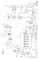
- FIG. 1 schematically illustrates a configuration surrounding a diesel engine 3 where a marine vessel denitration system 1 according to this embodiment is provided.
- the marine vessel is provided with the diesel engine (main engine) 3 for marine vessel propulsion, the denitration system 1 for denitrating exhaust gas from the diesel engine 3, a hybrid turbocharger 5 driven by exhaust gas from the diesel engine 3, and an exhaust gas economizer (exhaust gas boiler) 11 that generates steam using the exhaust gas from the diesel engine 3.
- the diesel engine (main engine) 3 for marine vessel propulsion
- the denitration system 1 for denitrating exhaust gas from the diesel engine 3
- a hybrid turbocharger 5 driven by exhaust gas from the diesel engine 3
- an exhaust gas economizer exhaust gas boiler
- Output from the diesel engine 3 is connected directly or indirectly to a screw propeller via a propeller shaft.
- An exhaust port of each of steam cylinder units 13 of the diesel engine 3 is connected to an exhaust manifold 15, which forms an exhaust gas collection pipe.
- the exhaust manifold 15 is connected to an inlet side of a turbine unit 5a of the hybrid turbocharger 5 via a first exhaust pipe L1.
- the denitration system 1 may be used for denitration of the exhaust gas from the electric power generating engines 61 and 63.
- each cylinder unit 13 An intake port of each cylinder unit 13 is connected to an intake manifold 17.
- the intake manifold 17 is connected to a compressor unit 5b of the hybrid turbocharger 5 via an intake pipe K1.
- An air cooler (intercooler) 18 is installed in the intake pipe K1.
- the hybrid turbocharger 5 includes the turbine unit 5a, the compressor unit 5b, and a hybrid electric power generator motor (electric power generator connected to a turbocharger) 5c.
- the turbine unit 5a, the compressor unit 5b, and the hybrid electric power generator motor 5c are coupled by a same rotating shaft 5d.
- the hybrid electric power generator motor 5c generates electric power using rotation energy from the turbine unit 5a and assists rotation of the compressor unit 5b by obtaining electric power from a marine vessel system 30.
- a converter 19 that converts alternating-current power to direct-current power
- an inverter 20 that converts direct-current power to alternating-current power
- an on-off switch 21 Provided between the hybrid electric power generator motor 5c and the marine vessel electric power system 30 are, in order from the hybrid electric power generator motor 5c side, a converter 19 that converts alternating-current power to direct-current power, an inverter 20 that converts direct-current power to alternating-current power and an on-off switch 21.
- a first electric power generating diesel engine 61 including an electric power generator 62, a second electric power generating diesel engine 63 including an electric power generator 64, a storage battery 67, photovoltaic power generator 69 and an external electric power input unit 71 are connected in parallel.
- a lithium ion secondary battery may, for example, be preferably used.
- the storage battery 67 is charged by electric power from the first electric power generating diesel engine 61, the second electric power generating diesel engine 63, the photovoltaic power generator 69 and the hybrid electric power generator motor 5c.
- the discharging and recharging of the storage battery 67 is performed by a control unit not illustrated in the drawings.
- the external electric power input unit 71 is supplied with electric power from an electric power source outside the marine vessel (an on-shore electric power source).
- the storage battery 67 is charged by the electric power supplied from the external electric power input unit 71.
- the marine vessel system 30 is connected to the ammonia producing device 2 and a later-described electric heater 73, and electric power is supplied to the ammonia producing device 2 and the electric heater 73.
- the exhaust gas economizer 11 is connected to a second exhaust pipe L2 on an outlet side of the turbine unit 5a of the hybrid turbocharger 5, and exhaust gas discharged from the main engine 3 and water supplied by a water supply pipe 23 are allowed to exchange heat so as to generate steam.
- an exhaust gas economizer on-off valve 22 that controls the flow of the exhaust gas is provided.
- a switching timing for the exhaust gas economizer on-off valve 22 is determined by a control unit not illustrated in the drawings.
- the marine vessel denitration system 1 includes the ammonia producing device 2 and an SCR catalyst unit 4 used for a selective catalytic reduction (SCR).
- the ammonia producing device 2 and the SCR catalyst unit 4 are connected to the second exhaust pipe L2, the ammonia producing device 2 being installed on the upstream side of the exhaust gas flow and the SCR catalyst unit 4 on the downstream side.
- the ammonia producing device 2 includes a hydrogen producing unit 81 that produces hydrogen from water, a nitrogen producing unit 83 that produces nitrogen from air, and an ammonia producing unit 80 that generates ammonia from the hydrogen and the nitrogen.
- pure water is used for the water used in the hydrogen producing unit 81.
- Fresh water is produced from sea water using a fresh water generator 85 mounted on the marine vessel and the fresh water is purified to pure water using a water purifier 87 mounted on the marine vessel.
- the hydrogen producing unit 81 uses a solid-state polymer electrolyte film method whereby an ion exchange film is used as an electrolyte to electrolyze pure water.
- the hydrogen produced by the hydrogen producing unit 81 is treated to remove moisture in a hydrogen drier (not illustrated in the drawings) and then fed to the ammonia producing unit 80.
- nitrogen producing unit 83 nitrogen is produced from air using a Pressure Swing Adsorption (PSA) method or the like.
- PSA Pressure Swing Adsorption
- the nitrogen produced by the nitrogen producing unit 83 is fed to the ammonia producing unit 80.
- the hydrogen and the nitrogen are mixed and heated, and ammonia is produced with a catalyst such as a ruthenium catalyst.
- the ammonia producing device 2 consumes electric power for the electrolysis and the like of the hydrogen producing unit 81. To provide such electric power, electric power from the above-described hybrid electric power generator motor 5c is used. As illustrated in FIG. 1 , the ammonia (gas) produced in the ammonia producing device 2 is supplied directly to the second exhaust pipe L2 via an ammonia producing device on-off valve 24. Thus, the produced ammonia is supplied directly into the exhaust gas without being stored on the way. A switching timing for the ammonia producing device on-off valve 24 is determined by the control unit not illustrated in the drawings.
- the exhaust gas is introduced to the SCR catalyst unit 4 from the second exhaust pipe L2 via an SCR on-off valve 26.
- a switching timing for the SCR on-off valve 26 is determined by the control unit not illustrated in the drawings.
- the NOx in the exhaust gas is selectively reduced by the catalyst and decomposed into non-hazardous nitrogen and steam.
- the electric heater 73 is provided for heating the exhaust gas that is to be introduced.
- the SCR on-off valve 26 and the exhaust gas economizer on-off valve 22 are opened and closed alternately. Specifically, when it is necessary to perform denitration of the exhaust gas, such as when the marine vessel is operating in areas where exhaust gas NOx regulations are strict, the SCR on-off valve 26 is opened and the exhaust gas economizer on-off valve 22 is closed. On the other hand, when it is not necessary to perform denitration of the exhaust gas, such as when the marine vessel is operating in areas where exhaust gas NOx regulations are relatively light, the SCR on-off valve 26 is closed and the exhaust gas economizer on-off valve 22 is opened. Note that the SCR on-off valve 26 and the exhaust gas economizer on-off valve 22 may be replaced with a three-way valve.
- the exhaust gas discharged from the diesel engine 3 is guided from the exhaust manifold 15 to the turbine unit 5a of the hybrid turbocharger 5 via the first exhaust pipe L1.
- the turbine unit 5a obtains the exhaust gas energy and is caused to rotate.
- the rotation energy is transmitted to the compressor unit 5b and the hybrid electric power generator motor 5c via the rotating shaft 5d.
- the compressor unit 5b air taken in (from the atmosphere) is compressed and fed to the intake manifold 17 via the air cooler 18.
- the hybrid electric power generator motor 5c electric power is generated from the rotation energy of the turbine unit 5a and the electric power output is supplied to the marine vessel system 30.
- the electric power from the hybrid electric power generator motor 5c is fed to the ammonia producing device 2 and used in the electrolysis in the hydrogen producing unit 81, a transfer pump that transfers the intermediate produced gas and produced ammonia, and the like. Further, the electric power output from the hybrid electric power generator motor 5c is supplied to the storage battery 67 connected to the marine vessel system 30.
- the photovoltaic power generator 69 is connected to the marine vessel system 30, and the electric power generated from sunlight is supplied to the marine vessel system 30, used to meet a load that is connected to the marine vessel system 30 and not illustrated in the drawings, and to charge the storage battery 67.
- the electric power generated by the electric power generating diesel engines 61 and 63 is similarly supplied to the marine vessel system 30, used to meet the load that is connected to the marine vessel system and not illustrated in the drawings, and to charge the storage battery 67.
- an electric power supply is received from the shore via the external electric power input unit 71, and the received electric power is used to meet the load that is connected to the marine vessel system 30 and not illustrated in the drawings, and to charge the storage battery 67.
- the electric power generating diesel engines 61 and 63 are preferably switched off.
- ammonia is produced from the hydrogen produced in the hydrogen producing unit 81 and the nitrogen produced in the nitrogen producing unit 83 using the electric power from the marine vessel system 30.
- Emission Control Area Emission Control Area
- denitration of the exhaust gas is performed.
- the exhaust gas economizer on-off valve 22 is closed, and the ammonia producing device on-off valve 24 and the SCR on-off valve 26 are opened.
- the exhaust gas discharged from the turbine unit 5a of the hybrid turbocharger 5 passes through the second exhaust pipe L2, and is mixed with the ammonia (gas) supplied from the ammonia producing device 2.
- the exhaust gas mixed with the ammonia is introduced to the SCR catalyst unit 4 via the SCR on-off valve 26.
- the electric heater 73 is turned on by the control unit not illustrated in the drawings and the exhaust gas is heated. On the other hand, if the exhaust gas temperature is equal to or higher than the predetermined value, the electric heater 73 is turned off by the control unit not illustrated in the drawings. The exhaust gas that has passed through the electric heater 73 undergoes denitration in the SCR catalyst unit 4 and is subsequently discharged to the outside from a funnel not illustrated in the drawings.
- ammonia producing device 2 ammonia can be produced on the marine vessel using water and air as raw materials. Hence, there is no need to provide space on the marine vessel to store a reducing agent such as liquid ammonia (such as ammonia aqueous solution) or urea. Hence, the marine vessel denitration system can be installed on the marine vessel without ensuring a large space.
- a reducing agent such as liquid ammonia (such as ammonia aqueous solution) or urea.
- the electric power output of the hybrid electric power generator motor 5c of the hybrid turbocharger 5 that generates electric power using the exhaust gas from the diesel engine 3 is supplied to the ammonia producing device 2.
- the ammonia producing device 2 can be operated with a low energy consumption.
- the exhaust energy from the diesel engine 3 can be used effectively and so it is possible to avoid increasing the capacity or a number of separately provided electric power generating auxiliary engines, such as diesel engine electric power generators.
- the electric power from the storage battery 67 can be used when fluctuations in the load on the diesel engine 3 result in fluctuations in the electric power output from the hybrid turbocharger 5.
- this arrangement is effective when the load on the diesel engine 3 is low and sufficient electric power output from the hybrid turbocharger 5 cannot be obtained.
- electric power can be supplied in a stable manner to the ammonia producing device 2.
- the storage battery 67 is connected to the same marine vessel system 30 as the hybrid turbocharger 5, the storage battery can be charged with excessive electric power generated by the electric power generator. Further, the inclusion of the storage battery enables load fluctuations to be suppressed and thus allows the capacity and size of the electric power generating diesel engines 61 and 63 to be reduced.
- the temperature of the exhaust gas flowing into the SCR catalyst unit 4 can be increased using the electric heater 73. Hence, deterioration of the SCR catalyst can be prevented. Further, the electric heater 73 uses electric power from the marine vessel system 30 that is connected to the storage battery 67, and can therefore receive a stable electric power supply.
- the photovoltaic power generator 69 is connected to the marine vessel system 30 and the electric power output of the photovoltaic power generator 69 is supplied to the storage battery 67, enabling a further improvement in the stability of the electric power supply.
- the external electric power input unit 71 for receiving an electric power supply from the shore is connected to the marine vessel system 30.
- the marine vessel can be supplied with electric power when berthed.
- the electric power output from the hybrid turbocharger 5 (see FIG. 1 ) is connected to the marine vessel system 30 and used in the denitration system.
- This embodiment differs in that the electric power output from a power turbine (gas turbine) is connected to the marine vessel system 30 and used in the denitration system. Accordingly, the same reference signs are used for other common constituents and repetitious descriptions are omitted.
- the hybrid turbocharger 5 (see FIG. 1 ) of the first embodiment is replaced with an exhaust gas turbocharger 5' as illustrated in FIG. 3 .
- the turbine unit 5a driven by the exhaust gas and the compressor unit 5b that compresses air are the same as in the first embodiment.
- a third exhaust pipe L3 is connected to the exhaust manifold 15, and exhaust gas from the diesel engine 3 is guided to an inlet side of a power turbine 7 via the third exhaust pipe L3.
- a portion of the exhaust gas from the diesel engine 3 is bled off and supplied to the power turbine 7.
- the power turbine 7 is driven to rotate by the bled exhaust gas.
- Exhaust gas discharged from an outlet side of the power turbine 7 is guided to the second exhaust pipe L2 via a fourth exhaust pipe L4.
- Rotation energy from the power turbine 7 is transmitted to a power turbine side electric power generator 33 via a rotational shaft 32.
- Electric power generated by the power turbine side electric power generator 33 is supplied to the marine vessel system 30 via the frequency converter 35 and the on/off switch 36. Accordingly, the electric power output from the power turbine side electric power generator 33 is supplied to the ammonia producing device 2.
- a load bank 44 is provided between the power turbine side electric power generator 33 and the frequency converter 35. For the load bank 44, a load resistance device is used. The load bank 44 is used to consume excessive electric power from the power turbine side electric power generator 33 and thereby reduce fluctuation in the output.
- An exhaust gas flow adjusting valve 37 for controlling an amount of gas introduced into the power turbine 7 is provided in the third exhaust pipe L3.
- a bypass valve 40 and an orifice 42 are provided between the third exhaust pipe L3 and the fourth exhaust pipe L4 to prevent over charging of the turbine unit 5a of the exhaust gas turbocharger 5' (charging that exceeds the optimal operating pressure of the engine) when the exhaust gas flow adjusting valve 37 is shut off.
- the electric power output from the power turbine side electric power generator 33 that generates electric power using the power turbine 7 driven by the exhaust gas from the diesel engine 3 is used in the ammonia producing device 2 via the marine vessel system 30. Hence, the exhaust energy from the diesel engine 3 can be used effectively.
- FIG. 4 a third embodiment of the present invention will be described using FIG. 4 .
- the electric power output from the power turbine 7 (see FIG. 3 ) is connected to the marine vessel system 30 and used in the denitration system.
- This embodiment differs in that the electric power output from a power turbine and a steam turbine is connected to the marine vessel system 30 and used in the denitration system. Accordingly, the same reference signs are used for other common constituents and repetitious descriptions are omitted.
- a steam turbine 9 is driven to rotate by steam generated by the exhaust gas economizer 11 and supplied via a first steam pipe J1.
- the exhaust gas economizer 11 receives exhaust gas discharged from the outlet side of the turbine unit 5a of the exhaust gas turbocharger 5' via the second exhaust pipe L2, and exhaust gas discharged from the outlet side of the power turbine 7 via a fourth exhaust pipe L4.
- Steam generated by the exhaust gas economizer 11 is introduced to the steam turbine 9 via the first steam pipe J1. After being used in the steam turbine 9, the steam is discharged using the second steam pipe J2 and guided to a condenser not illustrated in the drawings.
- the power turbine 7 and the steam turbine 9 are coupled in series to drive the heterogeneous turbine side electric power generator 50.
- the electric power generator 50 has different types (heterogeneous) of turbines, such as the power turbine 7 and the steam turbine 9, connected on the same shaft.
- Electric power generated by the heterogeneous turbine side electric power generator 50 is supplied to the marine vessel system 30 via the frequency converter 35 and the on/off switch 36. Accordingly, the electric power output from the heterogeneous turbine side electric power generator 50 is supplied to the ammonia producing device 2.
- a rotational shaft 52 of the steam turbine 9 is connected to the heterogeneous turbine side electric power generator 50 via a reduction gear and a coupling not illustrated in the drawings.
- the rotational shaft 32 of the power turbine 7 is coupled to the rotational shaft 52 of the steam turbine 9 via a reduction gear not illustrated in the drawings and a clutch 53.
- a clutch that engages and disengages at predetermined speeds such as a Synchro-Self-Shifting (SSS) clutch is favorably used.
- SSS Synchro-Self-Shifting
- the first steam pipe J1 is provided with a steam flow adjusting valve 54 for controlling an amount of steam introduced to the steam turbine 9 and an emergency shut-off valve 55 to shut off the supply of steam to the steam turbine 9 in an emergency.
- a steam bypass valve 57 is provided between the first steam pipe J1 and the second steam pipe J2 to adjust the flow rate of steam bypassing the steam turbine 7.
- Electric power is generated by the power turbine 7 driven by the exhaust gas from the diesel engine 3 and by the steam turbine 9 driven by steam generated by the exhaust gas economizer 11 using the exhaust gas from the diesel engine 3.
- the exhaust energy from the diesel engine 3 can be used more effectively.
- FIG. 5 a fourth embodiment of the present invention will be described using FIG. 5 .
- the electric power output from the power turbine 7 and the steam turbine 9 is connected to the marine vessel system 30 and used in the denitration system.
- This embodiment differs in that the electric power output from a heat transmitting medium turbine is connected to the marine vessel system 30 and used in the denitration system. Accordingly, the same reference signs are used for other common constituents and repetitious descriptions are omitted.
- a jacket water heat exchanger 90 is provided in a second cooling water pipe C2.
- Jacket water circulated through a first cooling water pipe C1 and a cylinder unit 13 by a circulation pump 48 is introduced to the jacket water heat exchanger 90, thereby heating cooling water introduced from a cooling water tank 46.
- Cooling water pumped from the cooling water tank 46 by a circulation pump 47 and heated in stages by being passed through a second air cooler 16 via the heat exchanger 90 and the second cooling water pipe C2 is introduced to a heat exchanger 89 by a third cooling water pipe C3.
- a heat transmitting medium turbine 8 is driven to rotate by supplying the heat transmitting medium vaporized by the heat exchanger 89 via a first heat transmitting medium pipe R1.
- the vaporized heat transmitting medium undergoes heat exchange with low-temperature heat transmitting medium in an economizer 95, and is then condensed in a condenser 97 and recirculated into the system by a circulation pump 99.
- the heat transmitting medium undergoes heat exchange with cooling water that has passed through the jacket water heat exchanger 90 and the second air cooler 16. Note, however, that a configuration in which the heat transmitting medium undergoes heat exchange with water heated by heat exchange with the exhaust gas from the engine is also possible.
- Rotation energy from the heat transmitting medium turbine 8 is transmitted to a heat transmitting medium turbine side electric power generator 93 via a rotational shaft 91.
- Electric power generated by the heat transmitting medium turbine side electric power generator 93 is supplied to the marine vessel system 30 via the frequency converter 35 and the on-off switch 36. Accordingly, the electric power output from the heat transmitting medium turbine side electric power generator 93 is supplied to the ammonia producing device 2.
- the electric power output from the heat transmitting medium turbine side electric power generator 93 that generates electric power using the heat transmitting medium turbine 8 driven by the heat transmitting medium vaporized through heat exchange with cooling water of the diesel engine 3 is used in the ammonia producing device 2 via the marine vessel system 30. Hence, the low-temperature exhaust energy from the diesel engine 3 can be used effectively.
- the power turbine 7, the third exhaust pipe L3, and the fourth exhaust pipe L4 may be omitted and electric power may be generated using the steam turbine 9 alone.
Landscapes
- Engineering & Computer Science (AREA)
- Chemical & Material Sciences (AREA)
- Combustion & Propulsion (AREA)
- Mechanical Engineering (AREA)
- General Engineering & Computer Science (AREA)
- Chemical Kinetics & Catalysis (AREA)
- Health & Medical Sciences (AREA)
- Environmental & Geological Engineering (AREA)
- Toxicology (AREA)
- Analytical Chemistry (AREA)
- Ocean & Marine Engineering (AREA)
- Organic Chemistry (AREA)
- Biomedical Technology (AREA)
- General Chemical & Material Sciences (AREA)
- Oil, Petroleum & Natural Gas (AREA)
- Inorganic Chemistry (AREA)
- General Health & Medical Sciences (AREA)
- Public Health (AREA)
- Exhaust Gas After Treatment (AREA)
- Engine Equipment That Uses Special Cycles (AREA)
- Exhaust Gas Treatment By Means Of Catalyst (AREA)
- Supercharger (AREA)
Abstract
Provided is a marine vessel denitration system capable of supplying, in a stable manner, the electrical energy required when producing ammonia for use as a reducing agent in denitration. Provided is the marine vessel denitration system (1) including: an ammonia producing device (2) that has a hydrogen producing unit (81) for producing hydrogen from water and a nitrogen producing unit (83) for producing nitrogen from air, and that produces ammonia from the hydrogen produced by the hydrogen producing unit (81) and the nitrogen produced by the nitrogen producing unit (83); and an SCR catalyst unit (4) that is provided in a second exhaust pipe (L2), which is an exhaust gas passage of a diesel engine (3) for marine vessel propulsion, and performs denitration of the exhaust gas with the ammonia produced by the ammonia producing device. The marine vessel denitration system (1) including: a hybrid turbocharger (5); and a storage battery (67), wherein an electric power output of the hybrid turbocharger (5) and the storage battery (67) is supplied to the ammonia producing device (2).
Description
- The present invention relates to a marine vessel denitration system mounted on a marine vessel and suitably used, for example, for denitration of exhaust gas from a diesel engine, and to a marine vessel equipped with the same.
- Denitration equipment is mounted on marine vessels to remove nitrogen oxide (NOx) produced by the diesel engine (main engine) used for marine vessel propulsion.
In the below-mentioned Patent Document 1, an invention which enables production of ammonia for use as a reducing agent of a denitration catalyst on a marine vessel is disclosed. Since the ammonia can be produced on the marine vessel, there is no need to transport liquid ammonia onto the marine vessel and store the liquid ammonia on the marine vessel. Moreover, liquid ammonia is handled as a hazardous material and so, if used, special storage equipment such as a leak detection sensor and double walled piping must be installed. However, if as much ammonia as required can be produced on the marine vessel, there is no need to install the special storage equipment. -
- {PTL 1}
Japanese Unexamined Patent Application Publication No.H11-292531 - To produce ammonia on the marine vessel, electrical energy is required to drive transfer pumps, perform electrolysis of water and the like. In the above-mentioned Patent Document 1, use of electric power from a diesel engine electric power generator which is an auxiliary engine is described.
However, generally speaking, because diesel engine electric power generators have a lower thermal efficiency than the main engine, when the electric power for producing ammonia is obtained from a diesel engine electric power generator, more energy is wasted. Hence, from the point of view of saving energy, use of the diesel engine electric power generator is not favorable.
It is desirable that the electric power required for producing ammonia is supplied in a stable manner irrespective of the electric power demand on the marine vessel, the load on the main engine or the like. - The present invention was conceived upon consideration of the above circumstances and has an objective of providing a marine vessel denitration system and a marine vessel equipped with the same, the marine vessel denitration system being capable of providing, with a low energy consumption, a stable supply of the electrical energy required when producing ammonia for use as a reducing agent for denitration.
- To solve the above-described problem, the marine vessel denitration system and the marine vessel equipped with the same of the present invention employs the following means.
Specifically, the marine vessel denitration system according to a first aspect of the present invention includes: an ammonia producing device that has a hydrogen producing unit for producing hydrogen from water and a nitrogen producing unit for producing nitrogen from air, and that produces ammonia from the hydrogen produced by the hydrogen producing unit and the nitrogen produced by the nitrogen producing unit; and a denitration catalyst unit that is provided in an exhaust gas passage of a main engine for marine vessel propulsion and/or an electric power generating engine, and that performs denitration of the exhaust gas with the ammonia produced by the ammonia producing device. The marine vessel denitration system includes an electric power generator that generates electric power using the exhaust energy from the main engine, and a storage battery electrically connected to the electric power generator, wherein the electric power generator and the storage battery are connected to an electric power system that supplies electric power to the ammonia producing device. - The ammonia producing device has the hydrogen producing unit that produces hydrogen from water and the nitrogen producing unit that produces nitrogen from air, and produces ammonia from the hydrogen and the nitrogen produced by the hydrogen producing unit and the nitrogen producing unit, respectively. Thus, the ammonia can be produced on the marine vessel using water and air as raw materials, and there is no need to provide space on the marine vessel for storing reducing agents such as liquid ammonia (aqueous ammonia solution or the like) or urea. Hence, the marine vessel denitration system can be installed on the marine vessel without ensuring a large space.
The electric power generator that generates electric power using the exhaust energy from the main engine is connected to the electric power system that supplies electric power to the ammonia producing device. Since the electric power output of the electric power generator is supplied to the ammonia producing device, the ammonia producing device can be operated with a low energy consumption. Also, the exhaust energy from the main engine can be used effectively and so it is possible to avoid increasing the capacity or a number of separately provided electric power generating auxiliary engines, such as diesel engine electric power generators.
Moreover, due to the inclusion of the storage battery connected to the electric power system that supplies electric power to the ammonia producing device, electric power from the storage battery can be used when fluctuations in the load on the main engine result in fluctuations in the electric power output from the electric power generator. This arrangement is particularly effective at a low load on the main engine when the sufficient electric power output from the electric power generator cannot be obtained. Hence, electric power can be supplied in a stable manner to the ammonia producing device. Further, because the storage battery is connected to the same electric power system as the electric power generator, excessive electric power generated by the electric power generator can be stored.
When an electric power generating engine is provided in the marine vessel, the inclusion of the storage battery suppresses load fluctuations and thus allows the capacity and size of the electric power generating engine to be reduced. - It is more preferable for the marine vessel denitration system according to the first aspect to include an electric heater that heats the exhaust gas being introduced to the denitration catalyst unit, and the electric heater is supplied with electric power from the electric power system.
- In a selective catalytic reduction (SCR) catalyst, which is the method mainly applied in denitration catalyst units, the risk of deterioration increases as the temperature of the exhaust gas decreases. According to the first aspect, the exhaust gas temperature is increased using the electric heater, and so deterioration of the SCR catalyst can be prevented.
The electric heater is supplied with electric power in a stable manner from the electric power system to which the electric power generator and the storage battery are connected. - Further, in the marine vessel denitration system according to the first aspect, photovoltaic power generator may be connected to the electric power system.
- Since the photovoltaic power generator is connected to the electric power system, electric power output from the photovoltaic power generator can be supplied to the storage battery. As a result, electric power can be supplied in a more stable manner.
- In the marine vessel denitration system according to the first aspect, an external electric power input unit for receiving electric power from an electric power source outside the marine vessel may be connected to the electric power system.
- The external electric power input unit for receiving an electric power supply from an electric power source outside the marine vessel is connected to the electric power system. Hence, the marine vessel can, for example, be supplied with electric power from an external (on shore) source when berthed. As a result, it is not necessary to run the electric power generating engine when the marine vessel is berthed, and a so-called zero emission state can thus be achieved.
- Further, in the marine vessel denitration system according to the first aspect, an electric power generator connected to a turbocharger generating electric power by obtaining rotation energy of an exhaust gas turbocharger of the main engine may be used as the electric power generator.
- One known example of a turbocharger including an electric power generator connected to a turbocharger that generates electric power by obtaining rotation energy of an exhaust gas turbocharger of the main engine is a hybrid turbocharger. Here, the electric power generator connected to a turbocharger is used as the electric power generator for supplying electric power to the ammonia producing device. As a result, the exhaust energy from the main engine can be used effectively.
- Further, in the marine vessel denitration system according to the first aspect, a power turbine side electric power generator that generates electric power with a power turbine driven by the exhaust gas from the main engine may be used as the electric power generator.
- Here, the output electric power from the power turbine side electric power generator that generates electric power with the power turbine driven by the exhaust gas from the main engine is used in the ammonia producing device. As a result, the exhaust energy from the main engine can be used effectively.
- Further, in the marine vessel denitration system according to the first aspect, a heterogeneous turbine side electric power generator that generates electric power using the power turbine driven by exhaust gas from the main engine and a steam turbine driven by steam generated with an exhaust gas boiler utilizing the exhaust gas from the main engine may be used as the electric power generator.
- In the heterogeneous turbine side electric power generator, different types (heterogeneous) of turbines such as a power turbine and a steam turbine are connected. When the heterogeneous turbine side electric power generator is used, electric power is generated using both the power turbine driven by the exhaust gas from the main engine and the steam turbine driven by steam generated with the exhaust gas boiler utilizing the exhaust gas from the main engine. Hence, the exhaust energy from the main engine can be used more effectively.
- Further, in the marine vessel denitration system according to the first aspect, a steam turbine side electric power generator that generates electric power with the steam turbine driven by steam generated with the exhaust gas boiler utilizing the exhaust gas from the main engine may be used as the electric power generator.
- In the marine vessel denitration system according to the first aspect, a heat transmitting medium turbine side electric power generator that generates electric power using a turbine driven by a vaporized heat transmitting medium may be used as the electric power generator, the heat transmitting medium being vaporized through heat exchange with heated water, and the heated water being heated by heat exchange with exhaust gas and/or cooling water of a jacket or an air cooler of the main engine.
Systems using alternative CFCs with a boiling point lower than water (such as R-245fa or R-134a), or organic heat transmitting media such as pentane or butane are well-known as the heat transmitting medium. Such systems make use of what is known as the Rankin cycle. - A marine vessel according to a second aspect of the present invention includes a main engine for marine vessel propulsion and/or an electric power generating engine, and any one of the above-described marine vessel denitration systems.
- Any of the above-described marine vessel denitration systems are capable of supplying electric power in a stable manner and is therefore suitable for installation in the marine vessel.
- According to the present invention, electric power output from an electric power generator generating electric power using exhaust energy from a main engine is utilized to produce ammonia. Hence, a marine vessel denitration system can be operated with a low energy consumption.
Moreover, a storage battery is provided. Hence, electric power from the storage battery can be used when fluctuations in the load on the main engine result in fluctuations in the electric power output from the electric power generator, and it is possible to supply electric power in a stable manner. -
- {
Fig. 1 }
FIG. 1 is a schematic view illustrating a configuration surrounding a diesel engine where a marine vessel denitration system according to a first embodiment of the present invention is provided. - {
Fig. 2 }
FIG. 2 is a schematic view illustrating an overview of an ammonia producing device depicted inFIG. 1 . - {
Fig. 3 }
FIG. 3 is a schematic view illustrating a configuration surrounding a diesel engine where a marine vessel denitration system according to a second embodiment of the present invention is provided. - {
Fig. 4 }
FIG. 4 is a schematic view illustrating a configuration surrounding a diesel engine where a marine vessel denitration system according to a third embodiment of the present invention is provided. - {
Fig. 5 }
FIG. 5 is a schematic view illustrating a configuration surrounding a diesel engine where a marine vessel denitration system according to a fourth embodiment of the present invention is provided. - Next, embodiments according to the present invention will be described while referring to the drawings.
- A first embodiment of the present invention will be described below using
FIG. 1 .
FIG. 1 schematically illustrates a configuration surrounding adiesel engine 3 where a marine vessel denitration system 1 according to this embodiment is provided.
The marine vessel is provided with the diesel engine (main engine) 3 for marine vessel propulsion, the denitration system 1 for denitrating exhaust gas from thediesel engine 3, ahybrid turbocharger 5 driven by exhaust gas from thediesel engine 3, and an exhaust gas economizer (exhaust gas boiler) 11 that generates steam using the exhaust gas from thediesel engine 3. - Output from the
diesel engine 3 is connected directly or indirectly to a screw propeller via a propeller shaft. An exhaust port of each ofsteam cylinder units 13 of thediesel engine 3 is connected to anexhaust manifold 15, which forms an exhaust gas collection pipe. Theexhaust manifold 15 is connected to an inlet side of aturbine unit 5a of thehybrid turbocharger 5 via a first exhaust pipe L1.
Note that the denitration system 1 may be used for denitration of the exhaust gas from the electricpower generating engines - An intake port of each
cylinder unit 13 is connected to anintake manifold 17. Theintake manifold 17 is connected to acompressor unit 5b of thehybrid turbocharger 5 via an intake pipe K1. An air cooler (intercooler) 18 is installed in the intake pipe K1. - The
hybrid turbocharger 5 includes theturbine unit 5a, thecompressor unit 5b, and a hybrid electric power generator motor (electric power generator connected to a turbocharger) 5c. Theturbine unit 5a, thecompressor unit 5b, and the hybrid electricpower generator motor 5c are coupled by a samerotating shaft 5d.
The hybrid electricpower generator motor 5c generates electric power using rotation energy from theturbine unit 5a and assists rotation of thecompressor unit 5b by obtaining electric power from amarine vessel system 30. Provided between the hybrid electricpower generator motor 5c and the marine vesselelectric power system 30 are, in order from the hybrid electricpower generator motor 5c side, aconverter 19 that converts alternating-current power to direct-current power, aninverter 20 that converts direct-current power to alternating-current power and an on-off switch 21. - In the
marine vessel system 30, a first electric power generatingdiesel engine 61 including anelectric power generator 62, a second electric power generatingdiesel engine 63 including anelectric power generator 64, astorage battery 67,photovoltaic power generator 69 and an external electricpower input unit 71 are connected in parallel.
For thestorage battery 67, a lithium ion secondary battery may, for example, be preferably used. Thestorage battery 67 is charged by electric power from the first electric power generatingdiesel engine 61, the second electric power generatingdiesel engine 63, thephotovoltaic power generator 69 and the hybrid electricpower generator motor 5c. The discharging and recharging of thestorage battery 67 is performed by a control unit not illustrated in the drawings.
The external electricpower input unit 71 is supplied with electric power from an electric power source outside the marine vessel (an on-shore electric power source). Thestorage battery 67 is charged by the electric power supplied from the external electricpower input unit 71.
Themarine vessel system 30 is connected to theammonia producing device 2 and a later-describedelectric heater 73, and electric power is supplied to theammonia producing device 2 and theelectric heater 73. - The
exhaust gas economizer 11 is connected to a second exhaust pipe L2 on an outlet side of theturbine unit 5a of thehybrid turbocharger 5, and exhaust gas discharged from themain engine 3 and water supplied by awater supply pipe 23 are allowed to exchange heat so as to generate steam. On an upstream side of theexhaust gas economizer 11, an exhaust gas economizer on-offvalve 22 that controls the flow of the exhaust gas is provided. A switching timing for the exhaust gas economizer on-offvalve 22 is determined by a control unit not illustrated in the drawings. - The marine vessel denitration system 1 includes the
ammonia producing device 2 and anSCR catalyst unit 4 used for a selective catalytic reduction (SCR). Theammonia producing device 2 and theSCR catalyst unit 4 are connected to the second exhaust pipe L2, theammonia producing device 2 being installed on the upstream side of the exhaust gas flow and theSCR catalyst unit 4 on the downstream side.
As illustrated inFIG. 2 , theammonia producing device 2 includes ahydrogen producing unit 81 that produces hydrogen from water, anitrogen producing unit 83 that produces nitrogen from air, and anammonia producing unit 80 that generates ammonia from the hydrogen and the nitrogen.
For the water used in thehydrogen producing unit 81, pure water is used. Fresh water is produced from sea water using afresh water generator 85 mounted on the marine vessel and the fresh water is purified to pure water using awater purifier 87 mounted on the marine vessel. Thehydrogen producing unit 81 uses a solid-state polymer electrolyte film method whereby an ion exchange film is used as an electrolyte to electrolyze pure water. The hydrogen produced by thehydrogen producing unit 81 is treated to remove moisture in a hydrogen drier (not illustrated in the drawings) and then fed to theammonia producing unit 80.
In thenitrogen producing unit 83, nitrogen is produced from air using a Pressure Swing Adsorption (PSA) method or the like. The nitrogen produced by thenitrogen producing unit 83 is fed to theammonia producing unit 80.
In theammonia producing unit 80, the hydrogen and the nitrogen are mixed and heated, and ammonia is produced with a catalyst such as a ruthenium catalyst. - The
ammonia producing device 2 consumes electric power for the electrolysis and the like of thehydrogen producing unit 81. To provide such electric power, electric power from the above-described hybrid electricpower generator motor 5c is used.
As illustrated inFIG. 1 , the ammonia (gas) produced in theammonia producing device 2 is supplied directly to the second exhaust pipe L2 via an ammonia producing device on-offvalve 24. Thus, the produced ammonia is supplied directly into the exhaust gas without being stored on the way. A switching timing for the ammonia producing device on-offvalve 24 is determined by the control unit not illustrated in the drawings. - The exhaust gas is introduced to the
SCR catalyst unit 4 from the second exhaust pipe L2 via an SCR on-offvalve 26. A switching timing for the SCR on-offvalve 26 is determined by the control unit not illustrated in the drawings. In theSCR catalyst unit 4, the NOx in the exhaust gas is selectively reduced by the catalyst and decomposed into non-hazardous nitrogen and steam.
On the upstream side of theSCR catalyst unit 4, theelectric heater 73 is provided for heating the exhaust gas that is to be introduced. - The SCR on-off
valve 26 and the exhaust gas economizer on-offvalve 22 are opened and closed alternately. Specifically, when it is necessary to perform denitration of the exhaust gas, such as when the marine vessel is operating in areas where exhaust gas NOx regulations are strict, the SCR on-offvalve 26 is opened and the exhaust gas economizer on-offvalve 22 is closed. On the other hand, when it is not necessary to perform denitration of the exhaust gas, such as when the marine vessel is operating in areas where exhaust gas NOx regulations are relatively light, the SCR on-offvalve 26 is closed and the exhaust gas economizer on-offvalve 22 is opened.
Note that the SCR on-offvalve 26 and the exhaust gas economizer on-offvalve 22 may be replaced with a three-way valve. - Next, an operating method for the marine vessel denitration system with the above-described configuration is described.
The exhaust gas discharged from thediesel engine 3 is guided from theexhaust manifold 15 to theturbine unit 5a of thehybrid turbocharger 5 via the first exhaust pipe L1. Theturbine unit 5a obtains the exhaust gas energy and is caused to rotate. The rotation energy is transmitted to thecompressor unit 5b and the hybrid electricpower generator motor 5c via therotating shaft 5d. With thecompressor unit 5b, air taken in (from the atmosphere) is compressed and fed to theintake manifold 17 via theair cooler 18.
With the hybrid electricpower generator motor 5c, electric power is generated from the rotation energy of theturbine unit 5a and the electric power output is supplied to themarine vessel system 30. The electric power from the hybrid electricpower generator motor 5c is fed to theammonia producing device 2 and used in the electrolysis in thehydrogen producing unit 81, a transfer pump that transfers the intermediate produced gas and produced ammonia, and the like.
Further, the electric power output from the hybrid electricpower generator motor 5c is supplied to thestorage battery 67 connected to themarine vessel system 30.
Thephotovoltaic power generator 69 is connected to themarine vessel system 30, and the electric power generated from sunlight is supplied to themarine vessel system 30, used to meet a load that is connected to themarine vessel system 30 and not illustrated in the drawings, and to charge thestorage battery 67.
The electric power generated by the electric power generatingdiesel engines marine vessel system 30, used to meet the load that is connected to the marine vessel system and not illustrated in the drawings, and to charge thestorage battery 67.
When the marine vessel is berthed, an electric power supply is received from the shore via the external electricpower input unit 71, and the received electric power is used to meet the load that is connected to themarine vessel system 30 and not illustrated in the drawings, and to charge thestorage battery 67. In this case, the electric power generatingdiesel engines - In the
ammonia producing device 2, ammonia is produced from the hydrogen produced in thehydrogen producing unit 81 and the nitrogen produced in thenitrogen producing unit 83 using the electric power from themarine vessel system 30. - When the marine vessel is operating in an Emission Control Area (ECA) where exhaust gas NOx regulations are strict, denitration of the exhaust gas is performed. In this case, the exhaust gas economizer on-off
valve 22 is closed, and the ammonia producing device on-offvalve 24 and the SCR on-offvalve 26 are opened.
The exhaust gas discharged from theturbine unit 5a of thehybrid turbocharger 5 passes through the second exhaust pipe L2, and is mixed with the ammonia (gas) supplied from theammonia producing device 2. The exhaust gas mixed with the ammonia is introduced to theSCR catalyst unit 4 via the SCR on-offvalve 26. If, before being introduced to theSCR catalyst unit 4, the exhaust gas temperature is lower than a predetermined value, theelectric heater 73 is turned on by the control unit not illustrated in the drawings and the exhaust gas is heated. On the other hand, if the exhaust gas temperature is equal to or higher than the predetermined value, theelectric heater 73 is turned off by the control unit not illustrated in the drawings. The exhaust gas that has passed through theelectric heater 73 undergoes denitration in theSCR catalyst unit 4 and is subsequently discharged to the outside from a funnel not illustrated in the drawings. - When the marine vessel is operating in areas where exhaust gas NOx regulations are relatively light, denitration of the exhaust gas is not performed. In this case, the exhaust gas economizer on-off
valve 22 is opened, and the ammonia producing device on-offvalve 24 and the SCR on-offvalve 26 are closed.
Exhaust gas discharged from theturbine unit 5a of thehybrid turbocharger 5 passes through the second exhaust pipe L2 and is introduced to theexhaust gas economizer 11 via the exhaust gas economizer on-offvalve 22. In theexhaust gas economizer 11, water supplied from thewater supply pipe 23 is heated by the exhaust gas to generate steam. The generated steam is used in various locations within the marine vessel. The exhaust gas discharged from theexhaust gas economizer 11 is discharged to the outside from a funnel not illustrated in the drawings. - As described above, the following effects are provided according to this embodiment.
With theammonia producing device 2, ammonia can be produced on the marine vessel using water and air as raw materials. Hence, there is no need to provide space on the marine vessel to store a reducing agent such as liquid ammonia (such as ammonia aqueous solution) or urea. Hence, the marine vessel denitration system can be installed on the marine vessel without ensuring a large space. - The electric power output of the hybrid electric
power generator motor 5c of thehybrid turbocharger 5 that generates electric power using the exhaust gas from thediesel engine 3 is supplied to theammonia producing device 2. As a result, theammonia producing device 2 can be operated with a low energy consumption. Also, the exhaust energy from thediesel engine 3 can be used effectively and so it is possible to avoid increasing the capacity or a number of separately provided electric power generating auxiliary engines, such as diesel engine electric power generators. - Due to the inclusion of the
storage battery 67 connected to themarine vessel system 30 that supplies electric power to theammonia producing device 2, the electric power from thestorage battery 67 can be used when fluctuations in the load on thediesel engine 3 result in fluctuations in the electric power output from thehybrid turbocharger 5. In particular, this arrangement is effective when the load on thediesel engine 3 is low and sufficient electric power output from thehybrid turbocharger 5 cannot be obtained. Hence, electric power can be supplied in a stable manner to theammonia producing device 2. Further, because thestorage battery 67 is connected to the samemarine vessel system 30 as thehybrid turbocharger 5, the storage battery can be charged with excessive electric power generated by the electric power generator.
Further, the inclusion of the storage battery enables load fluctuations to be suppressed and thus allows the capacity and size of the electric power generatingdiesel engines - The temperature of the exhaust gas flowing into the
SCR catalyst unit 4 can be increased using theelectric heater 73. Hence, deterioration of the SCR catalyst can be prevented. Further, theelectric heater 73 uses electric power from themarine vessel system 30 that is connected to thestorage battery 67, and can therefore receive a stable electric power supply. - The
photovoltaic power generator 69 is connected to themarine vessel system 30 and the electric power output of thephotovoltaic power generator 69 is supplied to thestorage battery 67, enabling a further improvement in the stability of the electric power supply. - The external electric
power input unit 71 for receiving an electric power supply from the shore is connected to themarine vessel system 30. Hence, the marine vessel can be supplied with electric power when berthed. As a result, it is not necessary to run the electric power generatingdiesel engines - Next, a second embodiment of the present invention will be described using
FIG. 3 . In the above-described first embodiment, the electric power output from the hybrid turbocharger 5 (seeFIG. 1 ) is connected to themarine vessel system 30 and used in the denitration system. This embodiment differs in that the electric power output from a power turbine (gas turbine) is connected to themarine vessel system 30 and used in the denitration system. Accordingly, the same reference signs are used for other common constituents and repetitious descriptions are omitted. - The hybrid turbocharger 5 (see
FIG. 1 ) of the first embodiment is replaced with an exhaust gas turbocharger 5' as illustrated inFIG. 3 . Theturbine unit 5a driven by the exhaust gas and thecompressor unit 5b that compresses air are the same as in the first embodiment. - A third exhaust pipe L3 is connected to the
exhaust manifold 15, and exhaust gas from thediesel engine 3 is guided to an inlet side of apower turbine 7 via the third exhaust pipe L3. Thus, before the exhaust gas from thediesel engine 3 is supplied to the exhaust gas turbocharger 5', a portion of the exhaust gas from thediesel engine 3 is bled off and supplied to thepower turbine 7. Thepower turbine 7 is driven to rotate by the bled exhaust gas.
Exhaust gas discharged from an outlet side of thepower turbine 7 is guided to the second exhaust pipe L2 via a fourth exhaust pipe L4. - Rotation energy from the
power turbine 7 is transmitted to a power turbine sideelectric power generator 33 via arotational shaft 32. Electric power generated by the power turbine sideelectric power generator 33 is supplied to themarine vessel system 30 via thefrequency converter 35 and the on/offswitch 36. Accordingly, the electric power output from the power turbine sideelectric power generator 33 is supplied to theammonia producing device 2.
Aload bank 44 is provided between the power turbine sideelectric power generator 33 and thefrequency converter 35. For theload bank 44, a load resistance device is used. Theload bank 44 is used to consume excessive electric power from the power turbine sideelectric power generator 33 and thereby reduce fluctuation in the output. - An exhaust gas
flow adjusting valve 37 for controlling an amount of gas introduced into thepower turbine 7 is provided in the third exhaust pipe L3. Abypass valve 40 and anorifice 42 are provided between the third exhaust pipe L3 and the fourth exhaust pipe L4 to prevent over charging of theturbine unit 5a of the exhaust gas turbocharger 5' (charging that exceeds the optimal operating pressure of the engine) when the exhaust gasflow adjusting valve 37 is shut off. - According to this embodiment, the following effects are provided in addition to the effects of the first embodiment.
The electric power output from the power turbine sideelectric power generator 33 that generates electric power using thepower turbine 7 driven by the exhaust gas from thediesel engine 3 is used in theammonia producing device 2 via themarine vessel system 30. Hence, the exhaust energy from thediesel engine 3 can be used effectively. - Next, a third embodiment of the present invention will be described using
FIG. 4 . In the above-described second embodiment, the electric power output from the power turbine 7 (seeFIG. 3 ) is connected to themarine vessel system 30 and used in the denitration system. This embodiment differs in that the electric power output from a power turbine and a steam turbine is connected to themarine vessel system 30 and used in the denitration system. Accordingly, the same reference signs are used for other common constituents and repetitious descriptions are omitted. - As illustrated in
FIG. 4 , asteam turbine 9 is driven to rotate by steam generated by theexhaust gas economizer 11 and supplied via a first steam pipe J1.
Theexhaust gas economizer 11 receives exhaust gas discharged from the outlet side of theturbine unit 5a of the exhaust gas turbocharger 5' via the second exhaust pipe L2, and exhaust gas discharged from the outlet side of thepower turbine 7 via a fourth exhaust pipe L4. Steam generated by theexhaust gas economizer 11 is introduced to thesteam turbine 9 via the first steam pipe J1. After being used in thesteam turbine 9, the steam is discharged using the second steam pipe J2 and guided to a condenser not illustrated in the drawings. - The
power turbine 7 and thesteam turbine 9 are coupled in series to drive the heterogeneous turbine sideelectric power generator 50. In other words, theelectric power generator 50 has different types (heterogeneous) of turbines, such as thepower turbine 7 and thesteam turbine 9, connected on the same shaft. Electric power generated by the heterogeneous turbine sideelectric power generator 50 is supplied to themarine vessel system 30 via thefrequency converter 35 and the on/offswitch 36. Accordingly, the electric power output from the heterogeneous turbine sideelectric power generator 50 is supplied to theammonia producing device 2. - A
rotational shaft 52 of thesteam turbine 9 is connected to the heterogeneous turbine sideelectric power generator 50 via a reduction gear and a coupling not illustrated in the drawings. Therotational shaft 32 of thepower turbine 7 is coupled to therotational shaft 52 of thesteam turbine 9 via a reduction gear not illustrated in the drawings and a clutch 53. For the clutch 53, a clutch that engages and disengages at predetermined speeds, such as a Synchro-Self-Shifting (SSS) clutch is favorably used. - The first steam pipe J1 is provided with a steam
flow adjusting valve 54 for controlling an amount of steam introduced to thesteam turbine 9 and an emergency shut-offvalve 55 to shut off the supply of steam to thesteam turbine 9 in an emergency. Asteam bypass valve 57 is provided between the first steam pipe J1 and the second steam pipe J2 to adjust the flow rate of steam bypassing thesteam turbine 7. - According to this embodiment, the following effects are provided in addition to the effects of the first embodiment and the second embodiment.
Electric power is generated by thepower turbine 7 driven by the exhaust gas from thediesel engine 3 and by thesteam turbine 9 driven by steam generated by theexhaust gas economizer 11 using the exhaust gas from thediesel engine 3. Hence, the exhaust energy from thediesel engine 3 can be used more effectively. - Next, a fourth embodiment of the present invention will be described using
FIG. 5 . In the above-described third embodiment, the electric power output from thepower turbine 7 and thesteam turbine 9 is connected to themarine vessel system 30 and used in the denitration system. This embodiment differs in that the electric power output from a heat transmitting medium turbine is connected to themarine vessel system 30 and used in the denitration system. Accordingly, the same reference signs are used for other common constituents and repetitious descriptions are omitted. - As illustrated in
FIG. 5 , a jacketwater heat exchanger 90 is provided in a second cooling water pipe C2. Jacket water circulated through a first cooling water pipe C1 and acylinder unit 13 by acirculation pump 48 is introduced to the jacketwater heat exchanger 90, thereby heating cooling water introduced from a coolingwater tank 46.
Cooling water pumped from the coolingwater tank 46 by acirculation pump 47 and heated in stages by being passed through asecond air cooler 16 via theheat exchanger 90 and the second cooling water pipe C2 is introduced to aheat exchanger 89 by a third cooling water pipe C3.
A heat transmittingmedium turbine 8 is driven to rotate by supplying the heat transmitting medium vaporized by theheat exchanger 89 via a first heat transmitting medium pipe R1. After being used in the heat transmittingmedium turbine 8, the vaporized heat transmitting medium undergoes heat exchange with low-temperature heat transmitting medium in aneconomizer 95, and is then condensed in acondenser 97 and recirculated into the system by acirculation pump 99.
In the configuration ofFIG. 5 , the heat transmitting medium undergoes heat exchange with cooling water that has passed through the jacketwater heat exchanger 90 and thesecond air cooler 16. Note, however, that a configuration in which the heat transmitting medium undergoes heat exchange with water heated by heat exchange with the exhaust gas from the engine is also possible. - Rotation energy from the heat transmitting
medium turbine 8 is transmitted to a heat transmitting medium turbine sideelectric power generator 93 via arotational shaft 91. Electric power generated by the heat transmitting medium turbine sideelectric power generator 93 is supplied to themarine vessel system 30 via thefrequency converter 35 and the on-off switch 36. Accordingly, the electric power output from the heat transmitting medium turbine sideelectric power generator 93 is supplied to theammonia producing device 2. - According to this embodiment, the following effects are provided in addition to the effects of the first embodiment, second embodiment, and third embodiment.
The electric power output from the heat transmitting medium turbine sideelectric power generator 93 that generates electric power using the heat transmittingmedium turbine 8 driven by the heat transmitting medium vaporized through heat exchange with cooling water of thediesel engine 3 is used in theammonia producing device 2 via themarine vessel system 30. Hence, the low-temperature exhaust energy from thediesel engine 3 can be used effectively. - In the above-described first embodiment and second embodiment, a configuration with an
exhaust gas economizer 11 is described. Note, however, that a configuration with theexhaust gas economizer 11 omitted is also possible. - Further, in the third embodiment, the
power turbine 7, the third exhaust pipe L3, and the fourth exhaust pipe L4 may be omitted and electric power may be generated using thesteam turbine 9 alone. -
{Reference Signs List} 1 Marine vessel denitration system 2 Ammonia producing device 3 Diesel engine (main engine) 4 SCR catalyst unit 5 Hybrid turbocharger 5' Exhaust gas turbocharger 5c Hybrid electric power generator motor (turbocharger side electric power generator) 7 Power turbine 8 Heat transmitting medium turbine 9 Steam turbine 11 Exhaust gas economizer (exhaust gas boiler) 30 Marine vessel electric power system 33 Power turbine side electric power generator 50 Heterogeneous turbine side electric power generator 67 Storage battery 69 Photovoltaic power generator 71 External electric power input unit 73 Electric heater 81 Hydrogen producing unit 83 Nitrogen producing unit 93 Heat transmitting medium turbine side electric power generator
Claims (10)
- A marine vessel denitration system, comprising: an ammonia producing device that includes a hydrogen producing unit for producing hydrogen from water and a nitrogen producing unit for producing nitrogen from air, and that produces ammonia from the hydrogen produced by the hydrogen producing unit and the nitrogen produced by the nitrogen producing unit; and
a denitration catalyst unit that is provided in an exhaust gas passage of a main engine for marine vessel propulsion and/or an electric power generating engine, and performs denitration of the exhaust gas with the ammonia produced by the ammonia producing device,
wherein the marine vessel denitration system comprising
an electric power generator that generates electric power using the exhaust energy from the main engine and/or the electric power generating engine; and
a storage battery electrically connected to the electric power generator, wherein
the electric power generator and the storage battery are connected to an electric power system that supplies electric power to the ammonia producing device. - The marine vessel denitration system according to claim 1, further comprising an electric heater that heats the exhaust gas to be introduced to the denitration catalyst unit, wherein
electric power for the electric heater is supplied from the electric power system. - The marine vessel denitration system according to claim 1 or 2, wherein a photovoltaic power generator is connected to the electric power system.
- The marine vessel denitration system according to any one of claims 1 to 3, wherein an external electric power input unit that receives an electric power supply from an electric power source outside a marine vessel is connected to the electric power system.
- The marine vessel denitration system according to any one of claims 1 to 4, wherein an electric power generator connected to a turbocharger generating electric power by obtaining rotation energy of an exhaust gas turbocharger of the main engine and/or the electric power generating engine is used as the electric power generator.
- The marine vessel denitration system according to any one of claims 1 to 5, wherein a power turbine side electric power generator that generates electric power using a power turbine driven by exhaust gas from the main engine and/or the electric power generating engine is used as the electric power generator.
- The marine vessel denitration system according to any one of claims 1 to 5, wherein a heterogeneous turbine side electric power generator that generates electric power using the power turbine driven by exhaust gas from the main engine and/or the electric power generating engine, and a steam turbine driven by steam generated with an exhaust gas boiler utilizing the exhaust gas from the main engine and/or the electric power generating engine is used as the electric power generator.
- The marine vessel denitration system according to any one of claims 1 to 5, wherein a steam turbine side electric power generator that generates electric power using a steam turbine driven by steam generated with an exhaust gas boiler utilizing the exhaust gas from the main engine and/or the electric power generating engine is used as the electric power generator.
- The marine vessel denitration system according to any one of claims 1 to 8, wherein a heat transmitting medium turbine side electric power generator that generates electric power using a turbine driven by a vaporized heat transmitting medium is used as the electric power generator, the heat transmitting medium being vaporized through heat exchange with heated water, the heated water being heated by heat exchange with exhaust gas and/or cooling water of a jacket or an air cooler from the main engine and/or the electric power generating engine.
- A marine vessel, comprising
a main engine for marine vessel propulsion and/or a electric power generating engine; and
the marine vessel denitration system according to any one of claims 1 to 9.
Applications Claiming Priority (2)
| Application Number | Priority Date | Filing Date | Title |
|---|---|---|---|
| JP2010189504A JP2012047095A (en) | 2010-08-26 | 2010-08-26 | Marine denitration system and marine vessel comprising the same |
| PCT/JP2011/068669 WO2012026387A1 (en) | 2010-08-26 | 2011-08-18 | Marine denitration system and ship provided with same |
Publications (1)
| Publication Number | Publication Date |
|---|---|
| EP2610453A1 true EP2610453A1 (en) | 2013-07-03 |
Family
ID=45723389
Family Applications (1)
| Application Number | Title | Priority Date | Filing Date |
|---|---|---|---|
| EP11819850.6A Withdrawn EP2610453A1 (en) | 2010-08-26 | 2011-08-18 | Marine denitration system and marine vessel equipped with the same |
Country Status (5)
| Country | Link |
|---|---|
| EP (1) | EP2610453A1 (en) |
| JP (1) | JP2012047095A (en) |
| KR (1) | KR20130026482A (en) |
| CN (1) | CN103026021A (en) |
| WO (1) | WO2012026387A1 (en) |
Cited By (1)
| Publication number | Priority date | Publication date | Assignee | Title |
|---|---|---|---|---|
| CN111392019A (en) * | 2020-03-27 | 2020-07-10 | 大连船舶重工集团有限公司 | Clean ship power system who discharges |
Families Citing this family (9)
| Publication number | Priority date | Publication date | Assignee | Title |
|---|---|---|---|---|
| CN103382885A (en) * | 2012-05-03 | 2013-11-06 | 天纳克(中国)有限公司 | Large-scale engine SCR denitration method and system |
| CN104302544B (en) * | 2012-05-28 | 2016-09-28 | 川崎重工业株式会社 | Primemover system and possess the boats and ships of this primemover system |
| US9387438B2 (en) | 2014-02-14 | 2016-07-12 | Tenneco Automotive Operating Company Inc. | Modular system for reduction of sulphur oxides in exhaust |
| JP6624965B2 (en) * | 2016-02-16 | 2019-12-25 | 三菱重工業株式会社 | Exhaust gas denitration apparatus and control method for exhaust gas denitration apparatus |
| JP6615076B2 (en) * | 2016-09-16 | 2019-12-04 | ヤンマー株式会社 | Ship |
| CN108331640A (en) * | 2017-12-20 | 2018-07-27 | 哈尔滨理工大学 | A kind of vehicle exhaust dust-extraction unit |
| KR102432774B1 (en) * | 2018-03-07 | 2022-08-17 | 대우조선해양 주식회사 | Linkage system using seawater electrolysis module |
| CN109436272B (en) * | 2018-12-28 | 2020-02-14 | 广州中国科学院沈阳自动化研究所分所 | Unmanned ship-oriented multi-power-source system and scheduling method thereof |
| CN116398817A (en) * | 2023-03-31 | 2023-07-07 | 江南造船(集团)有限责任公司 | A kind of ammonia evaporation gas treatment system, ammonia fuel supply system and ship |
Family Cites Families (9)
| Publication number | Priority date | Publication date | Assignee | Title |
|---|---|---|---|---|
| JP3339734B2 (en) * | 1993-10-15 | 2002-10-28 | 川崎重工業株式会社 | Exhaust gas purification equipment |
| JPH1032942A (en) * | 1996-07-12 | 1998-02-03 | Mitsubishi Heavy Ind Ltd | Power supply device for ship |
| JPH11292531A (en) * | 1998-04-16 | 1999-10-26 | Nkk Sogo Sekkei Kk | Marine ammonia production equipment for exhaust gas denitrification |
| DE102005026032A1 (en) * | 2005-06-03 | 2006-12-07 | Emitec Gesellschaft Für Emissionstechnologie Mbh | Device for exhaust gas treatment has particle separator, SCR catalyst for selectively reducing nitrogen oxides and ammonia generator for producing ammonia in the form of a selective reduction agent for reducing nitrogen oxides |
| JP4626878B2 (en) * | 2007-12-05 | 2011-02-09 | 西芝電機株式会社 | Inboard power system |
| JP5334470B2 (en) * | 2008-06-30 | 2013-11-06 | 三井造船株式会社 | Non-contact power supply system for ships, ship and ship power supply method |
| JP2010116847A (en) * | 2008-11-13 | 2010-05-27 | Mitsubishi Heavy Ind Ltd | Energy storage system for marine vessel |
| JP2010127239A (en) * | 2008-11-28 | 2010-06-10 | Mitsubishi Heavy Ind Ltd | Marine diesel engine |
| JP5173776B2 (en) * | 2008-12-15 | 2013-04-03 | 三菱重工業株式会社 | Exhaust energy recovery device |
-
2010
- 2010-08-26 JP JP2010189504A patent/JP2012047095A/en not_active Withdrawn
-
2011
- 2011-08-18 WO PCT/JP2011/068669 patent/WO2012026387A1/en not_active Ceased
- 2011-08-18 EP EP11819850.6A patent/EP2610453A1/en not_active Withdrawn
- 2011-08-18 KR KR1020137001708A patent/KR20130026482A/en not_active Ceased
- 2011-08-18 CN CN2011800364002A patent/CN103026021A/en active Pending
Non-Patent Citations (1)
| Title |
|---|
| See references of WO2012026387A1 * |
Cited By (1)
| Publication number | Priority date | Publication date | Assignee | Title |
|---|---|---|---|---|
| CN111392019A (en) * | 2020-03-27 | 2020-07-10 | 大连船舶重工集团有限公司 | Clean ship power system who discharges |
Also Published As
| Publication number | Publication date |
|---|---|
| KR20130026482A (en) | 2013-03-13 |
| CN103026021A (en) | 2013-04-03 |
| JP2012047095A (en) | 2012-03-08 |
| WO2012026387A1 (en) | 2012-03-01 |
Similar Documents
| Publication | Publication Date | Title |
|---|---|---|
| EP2610454A1 (en) | Marine vessel denitration system, marine vessel equipped with same, and control method for marine vessel denitration system | |
| EP2610453A1 (en) | Marine denitration system and marine vessel equipped with the same | |
| EP2610455A1 (en) | Marine vessil denitration system, marine vessel equipped with same, and control method for marine vessel denitration system | |
| US10066532B2 (en) | Electric supercharging device utilizing waste heat of internal combustion engine and power supplying method thereof | |
| US9096116B2 (en) | Drive with an internal combustion engine and an expansion machine with gas return | |
| JP5918722B2 (en) | Diesel engine and method for improving output of the diesel engine | |
| CN116729609A (en) | Ship ammonia-electricity hybrid power system with reversible fuel cell | |
| CN104487661B (en) | Internal combustion engine system, ship equipped with the internal combustion engine system, and operation method of the internal combustion engine system | |
| KR20150076718A (en) | System of recycling exhaust heat from internal combustion engine | |
| KR101496716B1 (en) | Waste heat recoverable power plant for ship | |
| EP2921659B1 (en) | Exhaust-heat recovery system and exhaust-heat recovery method | |
| JP2013032751A (en) | Engine system | |
| JP5965019B1 (en) | Fuel supply device | |
| CN105179104B (en) | It is a kind of to be applied to ship and the synthesis heat source system of ocean engineering field | |
| JP2011094536A (en) | Denitration device for ship, and ship provided therewith | |
| CN205135835U (en) | Synthesize heat source system for boats and ships and ocean engineering field | |
| EP2527244A1 (en) | System and method for providing heat on a ship | |
| CN116534234B (en) | A marine ammonia-electric hybrid system with an integrated cooling system | |
| CN116605397B (en) | A marine ammonia-electric hybrid power system based on fuel cell and engine gas path integration design | |
| JP2024143613A (en) | Engine System | |
| CN116291767A (en) | A turbine generator system and exhaust gas recovery power generation device |
Legal Events
| Date | Code | Title | Description |
|---|---|---|---|
| PUAI | Public reference made under article 153(3) epc to a published international application that has entered the european phase |
Free format text: ORIGINAL CODE: 0009012 |
|
| 17P | Request for examination filed |
Effective date: 20130225 |
|
| AK | Designated contracting states |
Kind code of ref document: A1 Designated state(s): AL AT BE BG CH CY CZ DE DK EE ES FI FR GB GR HR HU IE IS IT LI LT LU LV MC MK MT NL NO PL PT RO RS SE SI SK SM TR |
|
| STAA | Information on the status of an ep patent application or granted ep patent |
Free format text: STATUS: THE APPLICATION HAS BEEN WITHDRAWN |
|
| 18W | Application withdrawn |
Effective date: 20130705 |