EP2609982B1 - Adsorption rotor - Google Patents
Adsorption rotor Download PDFInfo
- Publication number
- EP2609982B1 EP2609982B1 EP12194744.4A EP12194744A EP2609982B1 EP 2609982 B1 EP2609982 B1 EP 2609982B1 EP 12194744 A EP12194744 A EP 12194744A EP 2609982 B1 EP2609982 B1 EP 2609982B1
- Authority
- EP
- European Patent Office
- Prior art keywords
- rotor
- adsorption rotor
- adsorption
- type
- detachment
- Prior art date
- Legal status (The legal status is an assumption and is not a legal conclusion. Google has not performed a legal analysis and makes no representation as to the accuracy of the status listed.)
- Active
Links
Images





Classifications
-
- B—PERFORMING OPERATIONS; TRANSPORTING
- B01—PHYSICAL OR CHEMICAL PROCESSES OR APPARATUS IN GENERAL
- B01D—SEPARATION
- B01D53/00—Separation of gases or vapours; Recovering vapours of volatile solvents from gases; Chemical or biological purification of waste gases, e.g. engine exhaust gases, smoke, fumes, flue gases, aerosols
- B01D53/02—Separation of gases or vapours; Recovering vapours of volatile solvents from gases; Chemical or biological purification of waste gases, e.g. engine exhaust gases, smoke, fumes, flue gases, aerosols by adsorption, e.g. preparative gas chromatography
- B01D53/06—Separation of gases or vapours; Recovering vapours of volatile solvents from gases; Chemical or biological purification of waste gases, e.g. engine exhaust gases, smoke, fumes, flue gases, aerosols by adsorption, e.g. preparative gas chromatography with moving adsorbents, e.g. rotating beds
-
- B—PERFORMING OPERATIONS; TRANSPORTING
- B01—PHYSICAL OR CHEMICAL PROCESSES OR APPARATUS IN GENERAL
- B01D—SEPARATION
- B01D53/00—Separation of gases or vapours; Recovering vapours of volatile solvents from gases; Chemical or biological purification of waste gases, e.g. engine exhaust gases, smoke, fumes, flue gases, aerosols
- B01D53/26—Drying gases or vapours
- B01D53/261—Drying gases or vapours by adsorption
-
- F—MECHANICAL ENGINEERING; LIGHTING; HEATING; WEAPONS; BLASTING
- F24—HEATING; RANGES; VENTILATING
- F24F—AIR-CONDITIONING; AIR-HUMIDIFICATION; VENTILATION; USE OF AIR CURRENTS FOR SCREENING
- F24F3/00—Air-conditioning systems in which conditioned primary air is supplied from one or more central stations to distributing units in the rooms or spaces where it may receive secondary treatment; Apparatus specially designed for such systems
- F24F3/12—Air-conditioning systems in which conditioned primary air is supplied from one or more central stations to distributing units in the rooms or spaces where it may receive secondary treatment; Apparatus specially designed for such systems characterised by the treatment of the air otherwise than by heating and cooling
- F24F3/14—Air-conditioning systems in which conditioned primary air is supplied from one or more central stations to distributing units in the rooms or spaces where it may receive secondary treatment; Apparatus specially designed for such systems characterised by the treatment of the air otherwise than by heating and cooling by humidification; by dehumidification
- F24F3/1411—Air-conditioning systems in which conditioned primary air is supplied from one or more central stations to distributing units in the rooms or spaces where it may receive secondary treatment; Apparatus specially designed for such systems characterised by the treatment of the air otherwise than by heating and cooling by humidification; by dehumidification by absorbing or adsorbing water, e.g. using an hygroscopic desiccant
- F24F3/1423—Air-conditioning systems in which conditioned primary air is supplied from one or more central stations to distributing units in the rooms or spaces where it may receive secondary treatment; Apparatus specially designed for such systems characterised by the treatment of the air otherwise than by heating and cooling by humidification; by dehumidification by absorbing or adsorbing water, e.g. using an hygroscopic desiccant with a moving bed of solid desiccants, e.g. a rotary wheel supporting solid desiccants
-
- F—MECHANICAL ENGINEERING; LIGHTING; HEATING; WEAPONS; BLASTING
- F28—HEAT EXCHANGE IN GENERAL
- F28D—HEAT-EXCHANGE APPARATUS, NOT PROVIDED FOR IN ANOTHER SUBCLASS, IN WHICH THE HEAT-EXCHANGE MEDIA DO NOT COME INTO DIRECT CONTACT
- F28D19/00—Regenerative heat-exchange apparatus in which the intermediate heat-transfer medium or body is moved successively into contact with each heat-exchange medium
- F28D19/04—Regenerative heat-exchange apparatus in which the intermediate heat-transfer medium or body is moved successively into contact with each heat-exchange medium using rigid bodies, e.g. mounted on a movable carrier
- F28D19/041—Regenerative heat-exchange apparatus in which the intermediate heat-transfer medium or body is moved successively into contact with each heat-exchange medium using rigid bodies, e.g. mounted on a movable carrier with axial flow through the intermediate heat-transfer medium
- F28D19/042—Rotors; Assemblies of heat absorbing masses
-
- B—PERFORMING OPERATIONS; TRANSPORTING
- B01—PHYSICAL OR CHEMICAL PROCESSES OR APPARATUS IN GENERAL
- B01D—SEPARATION
- B01D2253/00—Adsorbents used in seperation treatment of gases and vapours
- B01D2253/10—Inorganic adsorbents
- B01D2253/106—Silica or silicates
- B01D2253/108—Zeolites
-
- B—PERFORMING OPERATIONS; TRANSPORTING
- B01—PHYSICAL OR CHEMICAL PROCESSES OR APPARATUS IN GENERAL
- B01D—SEPARATION
- B01D2253/00—Adsorbents used in seperation treatment of gases and vapours
- B01D2253/30—Physical properties of adsorbents
- B01D2253/34—Specific shapes
- B01D2253/342—Monoliths
- B01D2253/3425—Honeycomb shape
-
- B—PERFORMING OPERATIONS; TRANSPORTING
- B01—PHYSICAL OR CHEMICAL PROCESSES OR APPARATUS IN GENERAL
- B01D—SEPARATION
- B01D2257/00—Components to be removed
- B01D2257/70—Organic compounds not provided for in groups B01D2257/00 - B01D2257/602
- B01D2257/708—Volatile organic compounds V.O.C.'s
-
- B—PERFORMING OPERATIONS; TRANSPORTING
- B01—PHYSICAL OR CHEMICAL PROCESSES OR APPARATUS IN GENERAL
- B01D—SEPARATION
- B01D2257/00—Components to be removed
- B01D2257/80—Water
-
- B—PERFORMING OPERATIONS; TRANSPORTING
- B01—PHYSICAL OR CHEMICAL PROCESSES OR APPARATUS IN GENERAL
- B01D—SEPARATION
- B01D2257/00—Components to be removed
- B01D2257/90—Odorous compounds not provided for in groups B01D2257/00 - B01D2257/708
-
- B—PERFORMING OPERATIONS; TRANSPORTING
- B01—PHYSICAL OR CHEMICAL PROCESSES OR APPARATUS IN GENERAL
- B01D—SEPARATION
- B01D2258/00—Sources of waste gases
- B01D2258/02—Other waste gases
- B01D2258/0258—Other waste gases from painting equipments or paint drying installations
-
- B—PERFORMING OPERATIONS; TRANSPORTING
- B01—PHYSICAL OR CHEMICAL PROCESSES OR APPARATUS IN GENERAL
- B01D—SEPARATION
- B01D2259/00—Type of treatment
- B01D2259/40—Further details for adsorption processes and devices
- B01D2259/40083—Regeneration of adsorbents in processes other than pressure or temperature swing adsorption
- B01D2259/40088—Regeneration of adsorbents in processes other than pressure or temperature swing adsorption by heating
-
- F—MECHANICAL ENGINEERING; LIGHTING; HEATING; WEAPONS; BLASTING
- F24—HEATING; RANGES; VENTILATING
- F24F—AIR-CONDITIONING; AIR-HUMIDIFICATION; VENTILATION; USE OF AIR CURRENTS FOR SCREENING
- F24F2203/00—Devices or apparatus used for air treatment
- F24F2203/10—Rotary wheel
- F24F2203/1012—Details of the casing or cover
-
- F—MECHANICAL ENGINEERING; LIGHTING; HEATING; WEAPONS; BLASTING
- F24—HEATING; RANGES; VENTILATING
- F24F—AIR-CONDITIONING; AIR-HUMIDIFICATION; VENTILATION; USE OF AIR CURRENTS FOR SCREENING
- F24F2203/00—Devices or apparatus used for air treatment
- F24F2203/10—Rotary wheel
- F24F2203/108—Rotary wheel comprising rotor parts shaped in sector form
-
- F—MECHANICAL ENGINEERING; LIGHTING; HEATING; WEAPONS; BLASTING
- F28—HEAT EXCHANGE IN GENERAL
- F28F—DETAILS OF HEAT-EXCHANGE AND HEAT-TRANSFER APPARATUS, OF GENERAL APPLICATION
- F28F2265/00—Safety or protection arrangements; Arrangements for preventing malfunction
- F28F2265/02—Safety or protection arrangements; Arrangements for preventing malfunction in the form of screens or covers
Definitions
- This invention is concerned with an adsorption rotor according to the preamble of claim 1 whose surface layers only need to be replaced, when performance of an adsorption rotor deteriorates, or when an adsorption rotor surface layer is got clogged.
- An adsorption rotor functions as either an absorber of volatile organic compounds (hereafter called "VOC") which are then released to make them denser, or as a dehumidifier by adsorbing moisture in air, using hydrophobic zeolite, activated carbon, hydrophilic zeolite, or silica gel.
- VOC volatile organic compounds
- adsorption rotor which functions as an adsorption-concentrator of VOC
- materials such materials as an activated carbon or a hydrophobic zeolite are used as adsorbents.
- a rotor using hydrophobic zeolite is nonflammable, and therefore has the advantage of avoiding in resulting into serious accident even if VOC adsorbed by the rotor may catch fire.
- both a hydrophilic zeolite and a hydrophobic zeolite have the heat resistance of more than 300 °C, and adsorbed VOC can be desorbed nearly completely by passing desorption air with a high temperature of not less than 300 °C, when VOC having a high boiling point are adsorbed by a certain cause.
- adsorption rotors used for the adsorption removal of VOC or for dehumidifier are manufactured as shown in Fig. 1 by considering the fabrication cost, where the whole unit is made up from the separate parts of metal aggregate boss 2, the reinforcement griddle 3, the perimeter angle 4, and the perimeter griddle 5.
- a large-sized rotor has a diameter of more than 4 m.
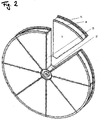
- it is divided into two or more sector pieces as shown in Fig. 2 , which is then assembled at the spot.
- the technology about such a divided-type adsorption rotor was disclosed in JP-A-2004-025132 .
- JP-A-2004-025132 shows a generic adsorption rotor according to the preamble of claim 1.
- the technology about the divided-type adsorption rotor equipped with two or more adsorption blocks having the capability of suppressing the crack formation in the rotor was disclosed in JP-A-2003-126641 .
- the exchange to a new adsorption rotor is required, when the rotor element deteriorates or performance of the above-mentioned adsorption rotor becomes lower, due to clogging on the rotor surface by dust accumulation due to operation for a long time, or paint mists being transformed to the liquid phase from the gaseous phase due to a temperature fall.
- the initial manufacturing cost of an integral-type rotor is comparatively cheap.
- a rotor will have to be decomposed compulsively, and it will have to be exchanged to a new rotor, resulting in the excessive time and effort of exchange and thus the increase in the cost of exchange.
- the initial cost of the divided-type rotor is comparatively high.
- it can be easily exchanged to a new sector piece by removing the bolts etc. which are fixing the sector piece, resulting in the decrease of the cost of exchange.
- the technology of equipping a fixed-type dust-collector was disclosed in JP-A-2006-090572 , which aims to prevent contamination of such a rotor, etc.
- the adsorption rotor of the present invention has enabled the attachment- and-detachment of an adsorption rotor surface side to be made only by changing the structure of metal aggregates.
- the present invention has an advantage that it can be introduced also into an already existing adsorption rotor, because there is no necessity in changes of an outer diameter etc.
- the honeycombs of the two adsorption rotor elements shift and a turbulent flow occurs in the flow of a wind inside the honeycombs. Due to this effect, a wind hits uniformly over the honeycombs, where adsorbents are attached, resulting in the improvement in performance, compared with the integral-type and divided-type adsorption rotor where a flow is laminar.
- the portion to be replaced is only a surface side, its weight is light.
- the portion to be replaced can be fixed using bolts, thus making special tools for this replacement procedures unnecessary, unskilled personnels can easily perform this work.
- the exchange time can be reduced to about 1/3 and the exchange cost is accordingly reduced, as compared with the adsorption rotor of an integral-type or a divided-type.
- the attachment-and-detachment procedures may be carried out during the system in operation.
- the detachment and replacement of only the surface side of an adsorption rotor can be easily carried out without increasing an initial cost and the attachment-and-detachment cost, when degradation and/or performance decrement, etc. of a rotor element occur.
- the conventional integral-type adsorption rotor has a shape as shown in Fig. 1 , where fan-shaped honeycombs 1 are fixed to the rotor integrally using the boss 2, the reinforcement griddle 3, the perimeter angle 4, and the perimeter griddle 5, all made of metal aggregates.
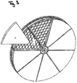
- the first embodiment of the present invention has shapes of either Fig. 3 or Fig. 6 and is of a type of the integral-type partially divided-type adsorption rotor.
- the attachment-and-detachment adsorption rotor element 6 is placed on the upper part of the integral-type adsorption rotor element 1 to protect it in the direction of the rotor width by being fixed using bolts at the perimeter griddle fixing bracket 7, which is made possible by extending the metal aggregates.
- the weight of the attachment-and-detachment adsorption rotor element 6 is light, thus enabling bolt-fixing to be made, unskilled personnels can easily carry out the detachment-and-attachment procedures without using special tools for the work.
- the air condition is such that personnels might enter the chamber wearing a protective garment, the procedures could be carried out while the rotor is in operation without using heavy industrial equipments, thus enabling substantial reduction of the replacement procedures to be made.
- the second embodiment of the present invention is described using Figs. 7 , 8 , and 9 .
- the diameter of the rotor exceeds 4 m, the weight of the attachment-and-detachment adsorption rotor element 6 becomes heavy.
- the metal aggregate 3a in Fig. 7 which protects the upper part of the integral-type adsorption rotor element 1, is put on the width direction of the rotor element so that the attachment-and-detachment adsorption rotor element 6 may pile up. Then, as shown in Fig.
- the attachment-and-detachment adsorption rotor element 6 is inserted into the metal aggregate 3a. Thereafter, as shown in Fig. 9 , the attachment-and-detachment adsorption rotor element 6 is held down by the perimeter griddle 8 from the adsorption rotor perimeter side, and is fixed using the perimeter griddle fixing elements 7 with bolts.
- a strong structure at the side of the perimeter of the attachment-and-detachment adsorption rotor element 6 or use of a large quantity of caulking, etc. become unnecessary, because leaks of processing air or reproduction air sre suppressed by the overlapping portion A of the perimeter angle 4 with the attachment-and-detachment adsorption rotor element 6.
- a catalyst element When concerns exist of polymerization of high boiling point substances adhering to the attachment-and-detachment rotor element, a catalyst element may be used. There is a concern of a surface of the rotor element catching fire if too much catalyst exists there. However, by reducing the amount of catalyst by making the width of the attachment-and-detachment rotor element thin as in the present invention, the danger of catching fire can be much reduced. Moreover, even when the composition of VOC to be processed changes somewhat, it is possible to change a hydrophobic zeolite used for an attachment-and-detachment adsorption rotor element into a different hydrophobic zeolite which may suit for the new composition.
- the length of a run-up section Xe which is the distance from the leading edge of the honeycombs to the point where laminar flow of air changes to turbulent is described by the following equation 1 using the Reynolds number Re for the equivalent diameter d of the honeycombs.
- the length of the run-up section Xe becomes 15.97 mm.
- the width of an attachment-and-detachment adsorption rotor element is made to more than the above-mentioned length of the run-up section and below half of the rotor width.
- Figure 4 shows a graph of the performance data which describes toluene concentrations on the abscissa (the horizontal axis) against the toluene extraction ratio on the ordinate (the vertical axis) for the conventional integral type or divided-type VOC adsorption rotor, and the integral-type partially divided-type VOC adsorption rotor by the present invention. It is evident that the toluene removal performance of the adsorption rotor by the present invention is better than the conventional adsorption rotor. This result is explained by the fact that, as shown in Fig.
- the present invention offers an adsorption rotor where only the surface side of an adsorption rotor can be detached and replaced, even if degradation and/or performance decrement, etc. of the adsorption rotor element occur. By this procedure, performance can be restored to an almost new state.
- the present invention provides an adsorption rotor which can be detached and replaced only of its surface layer.
- the metal aggregate is extended in the width direction of the rotor element so that the metal aggregate can fix the attachment-and-detachment adsorption rotor elements 6 by piling them up using bolts with the perimeter griddle fixing bracket 7, thus resulting in protecting the upper part of the integral-type adsorption rotor element.
- the weight of the attachment-and-detachment adsorption rotor elements 6 can be made light, resulting in them being fixable only using bolts, and thus of no necessity of using a special tool for the work, enabling unskilled personnels to easily carry out the detachment-and-replacement procedures.
- the detachment-and-replacement procedures can be performed from a rotor spindle side, thus from inside of a chamber, there is no necessity of using a heavy industrial machine etc., resulting in much reduction in the cost for the procedures.
Landscapes
- Engineering & Computer Science (AREA)
- Chemical & Material Sciences (AREA)
- Analytical Chemistry (AREA)
- General Chemical & Material Sciences (AREA)
- Oil, Petroleum & Natural Gas (AREA)
- Chemical Kinetics & Catalysis (AREA)
- Mechanical Engineering (AREA)
- General Engineering & Computer Science (AREA)
- Combustion & Propulsion (AREA)
- Physics & Mathematics (AREA)
- Thermal Sciences (AREA)
- Separation Of Gases By Adsorption (AREA)
Description
- This invention is concerned with an adsorption rotor according to the preamble of
claim 1 whose surface layers only need to be replaced, when performance of an adsorption rotor deteriorates, or when an adsorption rotor surface layer is got clogged. - An adsorption rotor functions as either an absorber of volatile organic compounds (hereafter called "VOC") which are then released to make them denser, or as a dehumidifier by adsorbing moisture in air, using hydrophobic zeolite, activated carbon, hydrophilic zeolite, or silica gel.
- For the case of an adsorption rotor which functions as an adsorption-concentrator of VOC, such materials as an activated carbon or a hydrophobic zeolite are used as adsorbents. Among these, a rotor using hydrophobic zeolite is nonflammable, and therefore has the advantage of avoiding in resulting into serious accident even if VOC adsorbed by the rotor may catch fire.
- Moreover, both a hydrophilic zeolite and a hydrophobic zeolite have the heat resistance of more than 300 °C, and adsorbed VOC can be desorbed nearly completely by passing desorption air with a high temperature of not less than 300 °C, when VOC having a high boiling point are adsorbed by a certain cause.
- The adsorption rotors used for the adsorption removal of VOC or for dehumidifier are manufactured as shown in
Fig. 1 by considering the fabrication cost, where the whole unit is made up from the separate parts ofmetal aggregate boss 2, thereinforcement griddle 3, theperimeter angle 4, and theperimeter griddle 5. On the other hand, a large-sized rotor has a diameter of more than 4 m. In order to facilitate easy handling in case of transporting the rotor to the installation spot, it is divided into two or more sector pieces as shown inFig. 2 , which is then assembled at the spot. The technology about such a divided-type adsorption rotor was disclosed inJP-A-2004-025132 JP-A-2004-025132 claim 1. In addition, the technology about the divided-type adsorption rotor equipped with two or more adsorption blocks having the capability of suppressing the crack formation in the rotor was disclosed inJP-A-2003-126641 - The exchange to a new adsorption rotor is required, when the rotor element deteriorates or performance of the above-mentioned adsorption rotor becomes lower, due to clogging on the rotor surface by dust accumulation due to operation for a long time, or paint mists being transformed to the liquid phase from the gaseous phase due to a temperature fall. The initial manufacturing cost of an integral-type rotor is comparatively cheap. However, when there is no exchange space, a rotor will have to be decomposed compulsively, and it will have to be exchanged to a new rotor, resulting in the excessive time and effort of exchange and thus the increase in the cost of exchange. On the other hand, the initial cost of the divided-type rotor is comparatively high. However, it can be easily exchanged to a new sector piece by removing the bolts etc. which are fixing the sector piece, resulting in the decrease of the cost of exchange. In addition, the technology of equipping a fixed-type dust-collector was disclosed in
JP-A-2006-090572 - As mentioned above, in the case of the integral-type adsorption rotor shown in
Fig. 1 , there occurs much futility of material because rotor elements other than the deteriorated surface will also be changed. Moreover, since the weight of the portion of the rotor to be exchanged becomes heavy, requiring a heavy industrial equipment etc. during the exchange and thus increasing a replacement cost. For the case of the divided-type adsorption rotor as shown inFig. 2 , it is necessary to strengthen every sector piece to be exchanged, in order to make metal aggregate strong enough as compared with an integral-type, resulting in the increase in an initial cost. In addition, whole rotor elements other than the deteriorated surface side have to be exchanged, resulting in much futility of material, similarly as for the case of the integral-type adsorption rotor. - For the case as disclosed in
JP-A-2006-090572 JP-A-2006- 090572 - It is an object of the present invention to further develop an adsorption rotor according to the preamble of
claim 1 such that only deteriorated portions can be detached and then be replaced by new portions without greatly increasing an initial cost and attachment-and-detachment cost, when degradation and/or performance decrement, etc. of an adsorption rotor element occur. - The object of the present invention is achieved by an adsorption rotor having the features of
claim 1. A further advantageous development of the present invention are defined in the dependent claim. - It is an advantage of the present invention to provide the ability of replacement of only the deteriorated surface side of an adsorption rotor, when degradation and/or performance decrement, etc. of an adsorption rotor element occur.
- The adsorption rotor of the present invention has enabled the attachment- and-detachment of an adsorption rotor surface side to be made only by changing the structure of metal aggregates. In addition, the present invention has an advantage that it can be introduced also into an already existing adsorption rotor, because there is no necessity in changes of an outer diameter etc.
- By dividing an adsorption rotor into a width direction and piling the divided portions up, the honeycombs of the two adsorption rotor elements shift and a turbulent flow occurs in the flow of a wind inside the honeycombs. Due to this effect, a wind hits uniformly over the honeycombs, where adsorbents are attached, resulting in the improvement in performance, compared with the integral-type and divided-type adsorption rotor where a flow is laminar.
- Moreover, since the portion to be replaced is only a surface side, its weight is light. Thus, because the portion to be replaced can be fixed using bolts, thus making special tools for this replacement procedures unnecessary, unskilled personnels can easily perform this work. By these means and arrangements, the exchange time can be reduced to about 1/3 and the exchange cost is accordingly reduced, as compared with the adsorption rotor of an integral-type or a divided-type. Moreover, in case of generating dry air for the dehumidifying purpose or of desorbing VOC for a painting plant, for example, if the quantity of air to be processed is at a level which does not affect a human body, the attachment-and-detachment procedures may be carried out during the system in operation.
-
- [
Figure 1] Figure 1 shows an oblique view of the conventional integral-type adsorption rotor. - [
Figure 2] Figure 2 shows an oblique view of the conventional divided-type adsorption rotor. - [
Figure 3] Figure 3 shows an oblique view of the first embodiment of the present invention of the integral-type partially divided-type adsorption rotor. (The first embodiment.) - [
Figure 4] Figure 4 shows a graph illustrating a comparison of the toluene extraction ratio for the conventional adsorption rotor and for the integral-type partially divided-type adsorption rotor of the present invention. - [
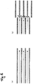
Figure 5] Figure 5 shows the flows of air in the honeycombs (a) in the conventional adsorption rotor and (b) in the integral-type partially divided-type adsorption rotor of the present invention. - [
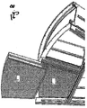
Figure 6] Figure 6 is an enlargement of the attachment-and-detachment portion of the adsorption rotor for the case of integral-type partially divided-type adsorption rotor of the present invention. (The first embodiment.) - [
Figure 7] Figure 7 is an oblique view of the perimeter portion of the integral-type partially divided-type adsorption rotor of the second embodiment of the present invention. (The second embodiment.) - [
Figure 8] Figure 8 shows the perimeter portion of the integral-type partially divided-type adsorption rotor of the present invention. (The second embodiment.) - [
Figure 9] Figure 9 shows the perimeter portion of the integral-type partially divided-type adsorption rotor of the present invention. (The second embodiment) - By the present invention, the detachment and replacement of only the surface side of an adsorption rotor can be easily carried out without increasing an initial cost and the attachment-and-detachment cost, when degradation and/or performance decrement, etc. of a rotor element occur.
- The conventional integral-type adsorption rotor has a shape as shown in
Fig. 1 , where fan-shaped honeycombs 1 are fixed to the rotor integrally using theboss 2, thereinforcement griddle 3, theperimeter angle 4, and theperimeter griddle 5, all made of metal aggregates. The first embodiment of the present invention has shapes of eitherFig. 3 orFig. 6 and is of a type of the integral-type partially divided-type adsorption rotor. Here, the attachment-and-detachment adsorption rotor element 6 is placed on the upper part of the integral-typeadsorption rotor element 1 to protect it in the direction of the rotor width by being fixed using bolts at the perimetergriddle fixing bracket 7, which is made possible by extending the metal aggregates. Because the weight of the attachment-and-detachment adsorption rotor element 6 is light, thus enabling bolt-fixing to be made, unskilled personnels can easily carry out the detachment-and-attachment procedures without using special tools for the work. Moreover, it is also possible to detach and replace the adsorbing rotor element 6 from the rotor shaft side, thus enabling the procedures to be carried out from inside the rotor chamber. Thus, if the air condition is such that personnels might enter the chamber wearing a protective garment, the procedures could be carried out while the rotor is in operation without using heavy industrial equipments, thus enabling substantial reduction of the replacement procedures to be made. - The second embodiment of the present invention is described using
Figs. 7 ,8 , and9 . In case the diameter of the rotor exceeds 4 m, the weight of the attachment-and-detachment adsorption rotor element 6 becomes heavy. In this case, it is advisable to divide the diameter of an adsorption rotor during the production process. For this case, the metal aggregate 3a inFig. 7 , which protects the upper part of the integral-typeadsorption rotor element 1, is put on the width direction of the rotor element so that the attachment-and-detachment adsorption rotor element 6 may pile up. Then, as shown inFig. 8 , the attachment-and-detachment adsorption rotor element 6 is inserted into the metal aggregate 3a. Thereafter, as shown inFig. 9 , the attachment-and-detachment adsorption rotor element 6 is held down by the perimeter griddle 8 from the adsorption rotor perimeter side, and is fixed using the perimetergriddle fixing elements 7 with bolts. Similarly as for the first embodiment of the present invention, a strong structure at the side of the perimeter of the attachment-and-detachment adsorption rotor element 6 or use of a large quantity of caulking, etc. become unnecessary, because leaks of processing air or reproduction air sre suppressed by the overlapping portion A of theperimeter angle 4 with the attachment-and-detachment adsorption rotor element 6. - With regard to the direction of piling up an attachment-and-detachment adsorption rotor element, when clogs at the side of an adsorption rotor processing entrance are anticipated due to paint mists etc. it is put on the processing entrance side for exchange, while when degradation at the reprocessing side of an adsorption rotor is anticipated due to heating polymerization, it is put on the reprocessing side for exchange there. It is possible to reuse the detached portion of the attachment-and-detachment rotor by carrying out calcination procedures. In this case, it is advisable to make the width to be 100 mm or less because, because if it is too wide, the calcination temperature will go up too much and will be damaged by fire at the time of calcination.
- When concerns exist of polymerization of high boiling point substances adhering to the attachment-and-detachment rotor element, a catalyst element may be used. There is a concern of a surface of the rotor element catching fire if too much catalyst exists there. However, by reducing the amount of catalyst by making the width of the attachment-and-detachment rotor element thin as in the present invention, the danger of catching fire can be much reduced. Moreover, even when the composition of VOC to be processed changes somewhat, it is possible to change a hydrophobic zeolite used for an attachment-and-detachment adsorption rotor element into a different hydrophobic zeolite which may suit for the new composition.
- It has already known that the length of a run-up section Xe, which is the distance from the leading edge of the honeycombs to the point where laminar flow of air changes to turbulent is described by the
following equation 1 using the Reynolds number Re for the equivalent diameter d of the honeycombs. For example, if the wind velocity is 2 m/s with the height of 1.8 mm and pitch of 3.4 mm of the honeycomb, respectively, the length of the run-up section Xe becomes 15.97 mm. When the flow of the wind in the honeycombs is turbulent, the probability that dusts contained in a wind, paint mist, etc. may adhere to the honeycomb surface becomes high. Therefore, the width of an attachment-and-detachment adsorption rotor element is made to more than the above-mentioned length of the run-up section and below half of the rotor width. -
Figure 4 shows a graph of the performance data which describes toluene concentrations on the abscissa (the horizontal axis) against the toluene extraction ratio on the ordinate (the vertical axis) for the conventional integral type or divided-type VOC adsorption rotor, and the integral-type partially divided-type VOC adsorption rotor by the present invention. It is evident that the toluene removal performance of the adsorption rotor by the present invention is better than the conventional adsorption rotor. This result is explained by the fact that, as shown inFig. 5 , (a) the flow of air in adsorption rotor honeycombs in the conventional integral-type or divided-type VOC adsorption rotor is laminar, while (b) in the case of the present invention where honeycombs are divided in the width direction, a gap arises in the honeycombs, resulting in the turbulent flow, and the air being processed uniformly hitting the downstream honeycombs where adsorbents are supported, and the latter led to the improvement in performance. This effect can be brought about by making the honeycomb size of the attachment-and-detachment adsorption rotor element 6 smaller than the integral-typeadsorption rotor element 1. - The present invention offers an adsorption rotor where only the surface side of an adsorption rotor can be detached and replaced, even if degradation and/or performance decrement, etc. of the adsorption rotor element occur. By this procedure, performance can be restored to an almost new state.
-
- 1: Adsorption rotor element
- 2: Boss
- 3: Reinforcement griddle
- 4: Perimeter angle
- 5: Perimeter griddle
- 6: Attachment-and-detachment adsorption rotor element
- 7: Perimeter griddle fixing bracket
- 8: Perimeter griddle for attachment-and-detachment elements
- [Objective] When performance of an adsorption rotor falls, or even if an adsorption rotor surface layer gets clogged, the present invention provides an adsorption rotor which can be detached and replaced only of its surface layer.
[The means of solution] The metal aggregate is extended in the width direction of the rotor element so that the metal aggregate can fix the attachment-and-detachment adsorption rotor elements 6 by piling them up using bolts with the perimetergriddle fixing bracket 7, thus resulting in protecting the upper part of the integral-type adsorption rotor element. In this way, the weight of the attachment-and-detachment adsorption rotor elements 6 can be made light, resulting in them being fixable only using bolts, and thus of no necessity of using a special tool for the work, enabling unskilled personnels to easily carry out the detachment-and-replacement procedures. Moreover, because the detachment-and-replacement procedures can be performed from a rotor spindle side, thus from inside of a chamber, there is no necessity of using a heavy industrial machine etc., resulting in much reduction in the cost for the procedures.
Claims (2)
- An adsorption rotor comprising honeycomb-shaped adsorption elements (1, 6), the honeycomb-shaped adsorption elements (1, 6) being installed in a metal aggregate (3, 3a, 4-8) which is combined with a boss (2),
characterized in that
the adsorption rotor comprises at least two layers of honeycomb-shaped adsorption elements (1, 6), the thickness of one honeycomb-shaped adsorption element layer (6), which is located at a surface side of the adsorption rotor, being smaller than the thickness of the other honeycomb-shaped adsorption element layer (1) and in that said thinner honeycomb-shaped adsorption element (6) is divided into two or more fan-shaped sectors which are detachably and replaceably installed to the metal aggregate. - The adsorption rotor described in claim 1, wherein the fan-shaped sectors are insertable into the metal aggregate (3, 3a, 4-8) in the direction of a circumference of the adsorption rotor.
Applications Claiming Priority (1)
| Application Number | Priority Date | Filing Date | Title |
|---|---|---|---|
| JP2011284932A JP5826627B2 (en) | 2011-12-27 | 2011-12-27 | Adsorption rotor |
Publications (2)
| Publication Number | Publication Date |
|---|---|
| EP2609982A1 EP2609982A1 (en) | 2013-07-03 |
| EP2609982B1 true EP2609982B1 (en) | 2016-03-16 |
Family
ID=47257652
Family Applications (1)
| Application Number | Title | Priority Date | Filing Date |
|---|---|---|---|
| EP12194744.4A Active EP2609982B1 (en) | 2011-12-27 | 2012-11-29 | Adsorption rotor |
Country Status (4)
| Country | Link |
|---|---|
| US (1) | US8876957B2 (en) |
| EP (1) | EP2609982B1 (en) |
| JP (1) | JP5826627B2 (en) |
| ES (1) | ES2567953T3 (en) |
Families Citing this family (17)
| Publication number | Priority date | Publication date | Assignee | Title |
|---|---|---|---|---|
| JP6528094B2 (en) * | 2015-04-08 | 2019-06-12 | シャープ株式会社 | Water accumulation device and water accumulation method |
| CN105289196B (en) * | 2015-11-11 | 2018-07-24 | 烟台艾森信息技术股份有限公司 | A kind of adsorption separation device and system |
| CN105387536A (en) * | 2015-12-14 | 2016-03-09 | 泰州市日高冷机有限公司 | Split type absorbing rotary plate and rotary wheel dehumidifier applying absorbing rotary plate |
| CN105387535A (en) * | 2015-12-14 | 2016-03-09 | 泰州市日高冷机有限公司 | Split type absorbing rotary plate and rotary wheel dehumidifier applying absorbing rotary plate |
| CN105402831A (en) * | 2015-12-14 | 2016-03-16 | 泰州市日高冷机有限公司 | Adsorption rotary disc and rotary dehumidifier with adsorption rotary disc |
| EP3225856B1 (en) * | 2016-03-30 | 2018-11-28 | Aufrecht GmbH | Mounter |
| US10295272B2 (en) * | 2016-04-05 | 2019-05-21 | Arvos Ljungstrom Llc | Rotary pre-heater for high temperature operation |
| EP3501621B1 (en) * | 2016-08-17 | 2021-07-14 | Nichias Corporation | Absorption rotor and absorption rotor manufacturing method |
| TWI624297B (en) * | 2016-11-22 | 2018-05-21 | 傑智環境科技股份有限公司 | Rotary Wheel Having Enhanced Structural Strength And Fluid Processing Equipment Including The Same |
| US20190120566A1 (en) * | 2017-04-05 | 2019-04-25 | Arvos Ljungstrom Llc | A rotary pre-heater for high temperature operation |
| US10989434B2 (en) | 2018-12-20 | 2021-04-27 | Johnson Controls Technology Company | Removable energy recovery wheel assembly for an HVAC system |
| US11041679B2 (en) | 2019-01-21 | 2021-06-22 | Johnson Controls Technology Company | Energy recovery wheel assembly for an HVAC system |
| JP7347795B2 (en) * | 2019-12-16 | 2023-09-20 | 株式会社西部技研 | Organic solvent concentrator and method for determining deterioration of organic solvent concentrator |
| CN112503749A (en) * | 2020-09-27 | 2021-03-16 | 西部技研环保节能设备(常熟)有限公司 | Antibacterial and antiviral honeycomb rotating wheel with copper ion dissolving agent surface coating for air conditioner |
| JP7132475B1 (en) * | 2021-12-27 | 2022-09-07 | 岡野 浩志 | Carbon dioxide gas separator/concentrator capable of supplying air conditioning |
| JP2023158284A (en) | 2022-04-18 | 2023-10-30 | 株式会社西部技研 | Adsorption rotor and its storage device |
| CN115193225B (en) * | 2022-07-21 | 2024-03-22 | 江西科霖环保装备有限公司 | VOCs organic waste gas treatment device |
Family Cites Families (17)
| Publication number | Priority date | Publication date | Assignee | Title |
|---|---|---|---|---|
| US3314472A (en) * | 1964-08-25 | 1967-04-18 | Air Preheater | Element basket for heat exchanger |
| US3789916A (en) * | 1971-04-06 | 1974-02-05 | Munters Ab Carl | Rotor for exchangers of the thermodynamic characteristics of two gas currents |
| JPS56136622A (en) * | 1980-03-28 | 1981-10-26 | Mitsubishi Heavy Ind Ltd | Stack gas desulfurizer |
| JPS56158125A (en) * | 1980-05-13 | 1981-12-05 | Mitsubishi Heavy Ind Ltd | Replacing method for packed layer of gas-treating apparatus |
| US5169414A (en) * | 1990-07-03 | 1992-12-08 | Flakt, Inc. | Rotary adsorption assembly |
| US5057128A (en) * | 1990-07-03 | 1991-10-15 | Flakt, Inc. | Rotary adsorption assembly |
| US5960166A (en) * | 1993-10-01 | 1999-09-28 | Lexmark International, Inc. | Image printing solution for a printing device |
| US5595238A (en) * | 1994-09-16 | 1997-01-21 | Engelhard/Icc | Rotatably supported regenerative fluid treatment wheel assemblies |
| US5702508A (en) * | 1996-01-25 | 1997-12-30 | Moratalla; Jose | Ceramic desiccant device |
| JPH10156128A (en) * | 1996-12-04 | 1998-06-16 | Chugai Ro Co Ltd | Rotary cylinder type gas concentrator |
| JP2000117039A (en) * | 1998-10-15 | 2000-04-25 | Toshiba Corp | Gas separation device |
| JP4413334B2 (en) * | 1999-10-20 | 2010-02-10 | アルストム株式会社 | Regenerative carbon dioxide separator and carbon dioxide separation system |
| KR100409253B1 (en) * | 2000-03-30 | 2003-12-18 | 니찌아스 카부시키카이샤 | Rotor and sealing device for rotary adsorber |
| JP3948248B2 (en) * | 2001-10-29 | 2007-07-25 | ダイキン工業株式会社 | Adsorption rotor and adsorption apparatus using the same |
| DE10157550C2 (en) * | 2001-11-23 | 2003-09-18 | Klingenburg Gmbh | Sorption |
| JP2004025132A (en) * | 2002-06-28 | 2004-01-29 | Seibu Giken Co Ltd | Adsorption rotor |
| JP2006090572A (en) | 2004-09-21 | 2006-04-06 | Sanden Corp | Air conditioner |
-
2011
- 2011-12-27 JP JP2011284932A patent/JP5826627B2/en active Active
-
2012
- 2012-11-29 EP EP12194744.4A patent/EP2609982B1/en active Active
- 2012-11-29 ES ES12194744.4T patent/ES2567953T3/en active Active
- 2012-12-27 US US13/728,049 patent/US8876957B2/en active Active
Also Published As
| Publication number | Publication date |
|---|---|
| JP2013132603A (en) | 2013-07-08 |
| EP2609982A1 (en) | 2013-07-03 |
| US20130186277A1 (en) | 2013-07-25 |
| ES2567953T3 (en) | 2016-04-26 |
| US8876957B2 (en) | 2014-11-04 |
| JP5826627B2 (en) | 2015-12-02 |
Similar Documents
| Publication | Publication Date | Title |
|---|---|---|
| EP2609982A1 (en) | Adsorption rotor | |
| US8440002B2 (en) | Long life pyramidal filter for gas turbine inlet system | |
| JP5749817B2 (en) | Vertical baffle of horizontal adsorbent container | |
| EP4170080B1 (en) | Adsorption rotor, adsorption treatment device, and treatment system | |
| US20230058004A1 (en) | Gas filter separator filter cartridge with keys and/or baffle | |
| JP5675726B2 (en) | Radioactive gas removal device | |
| JP7146642B2 (en) | Filter Cartridge System for Control of Airborne Molecular Contamination | |
| JP5776672B2 (en) | Activated carbon cartridge and gas purification device | |
| CN102091488A (en) | Rotating wheel paint-mist purification device | |
| CN206103654U (en) | Low concentration VOCs contaminated air adsorbs purifier and system thereof | |
| CN104623983B (en) | The tower reactor of oscillating mode demister it is provided with in a kind of | |
| CA2747907C (en) | Refillable filter system | |
| TWI517893B (en) | Rotating wheel, fluid treatment apparatus, method for removing treatment block of the rotating wheel, and method for removing treatment frame of the rotating wheel | |
| KR102055221B1 (en) | Method for adsorpting and concentrating toxic compound | |
| CN201921611U (en) | Rotating wheel paint mist purifying device | |
| JP2004209420A (en) | Dehumidification element and dehumidification apparatus | |
| KR101264415B1 (en) | Rotary VOC Concentrator using Pellet Adsorbent | |
| CN210980922U (en) | Waste heat recovery device for coating processing | |
| CN206008298U (en) | A mobile dust removal adsorption waste gas purification device | |
| JP4982704B2 (en) | Gas purification device | |
| CN108654234A (en) | A kind of air pollution control device and its application method | |
| KR20130001959U (en) | Rotation filter system and bulk surge tank having the same | |
| JP5978808B2 (en) | Wastewater treatment system | |
| KR101448422B1 (en) | Installation structure of pre filter for gas adsorption tower that heighten filtration area | |
| CN114845793A (en) | Pleated filter element for an air filter |
Legal Events
| Date | Code | Title | Description |
|---|---|---|---|
| PUAI | Public reference made under article 153(3) epc to a published international application that has entered the european phase |
Free format text: ORIGINAL CODE: 0009012 |
|
| AK | Designated contracting states |
Kind code of ref document: A1 Designated state(s): AL AT BE BG CH CY CZ DE DK EE ES FI FR GB GR HR HU IE IS IT LI LT LU LV MC MK MT NL NO PL PT RO RS SE SI SK SM TR |
|
| AX | Request for extension of the european patent |
Extension state: BA ME |
|
| 17P | Request for examination filed |
Effective date: 20131223 |
|
| 17Q | First examination report despatched |
Effective date: 20140626 |
|
| GRAP | Despatch of communication of intention to grant a patent |
Free format text: ORIGINAL CODE: EPIDOSNIGR1 |
|
| INTG | Intention to grant announced |
Effective date: 20150828 |
|
| GRAS | Grant fee paid |
Free format text: ORIGINAL CODE: EPIDOSNIGR3 |
|
| GRAA | (expected) grant |
Free format text: ORIGINAL CODE: 0009210 |
|
| AK | Designated contracting states |
Kind code of ref document: B1 Designated state(s): AL AT BE BG CH CY CZ DE DK EE ES FI FR GB GR HR HU IE IS IT LI LT LU LV MC MK MT NL NO PL PT RO RS SE SI SK SM TR |
|
| REG | Reference to a national code |
Ref country code: GB Ref legal event code: FG4D |
|
| REG | Reference to a national code |
Ref country code: CH Ref legal event code: EP |
|
| REG | Reference to a national code |
Ref country code: IE Ref legal event code: FG4D |
|
| REG | Reference to a national code |
Ref country code: AT Ref legal event code: REF Ref document number: 780701 Country of ref document: AT Kind code of ref document: T Effective date: 20160415 |
|
| REG | Reference to a national code |
Ref country code: ES Ref legal event code: FG2A Ref document number: 2567953 Country of ref document: ES Kind code of ref document: T3 Effective date: 20160426 |
|
| REG | Reference to a national code |
Ref country code: DE Ref legal event code: R096 Ref document number: 602012015616 Country of ref document: DE |
|
| REG | Reference to a national code |
Ref country code: SE Ref legal event code: TRGR |
|
| REG | Reference to a national code |
Ref country code: NL Ref legal event code: MP Effective date: 20160316 |
|
| REG | Reference to a national code |
Ref country code: LT Ref legal event code: MG4D |
|
| PG25 | Lapsed in a contracting state [announced via postgrant information from national office to epo] |
Ref country code: NO Free format text: LAPSE BECAUSE OF FAILURE TO SUBMIT A TRANSLATION OF THE DESCRIPTION OR TO PAY THE FEE WITHIN THE PRESCRIBED TIME-LIMIT Effective date: 20160616 Ref country code: GR Free format text: LAPSE BECAUSE OF FAILURE TO SUBMIT A TRANSLATION OF THE DESCRIPTION OR TO PAY THE FEE WITHIN THE PRESCRIBED TIME-LIMIT Effective date: 20160617 Ref country code: FI Free format text: LAPSE BECAUSE OF FAILURE TO SUBMIT A TRANSLATION OF THE DESCRIPTION OR TO PAY THE FEE WITHIN THE PRESCRIBED TIME-LIMIT Effective date: 20160316 Ref country code: HR Free format text: LAPSE BECAUSE OF FAILURE TO SUBMIT A TRANSLATION OF THE DESCRIPTION OR TO PAY THE FEE WITHIN THE PRESCRIBED TIME-LIMIT Effective date: 20160316 |
|
| REG | Reference to a national code |
Ref country code: AT Ref legal event code: MK05 Ref document number: 780701 Country of ref document: AT Kind code of ref document: T Effective date: 20160316 |
|
| PG25 | Lapsed in a contracting state [announced via postgrant information from national office to epo] |
Ref country code: LT Free format text: LAPSE BECAUSE OF FAILURE TO SUBMIT A TRANSLATION OF THE DESCRIPTION OR TO PAY THE FEE WITHIN THE PRESCRIBED TIME-LIMIT Effective date: 20160316 Ref country code: LV Free format text: LAPSE BECAUSE OF FAILURE TO SUBMIT A TRANSLATION OF THE DESCRIPTION OR TO PAY THE FEE WITHIN THE PRESCRIBED TIME-LIMIT Effective date: 20160316 Ref country code: RS Free format text: LAPSE BECAUSE OF FAILURE TO SUBMIT A TRANSLATION OF THE DESCRIPTION OR TO PAY THE FEE WITHIN THE PRESCRIBED TIME-LIMIT Effective date: 20160316 Ref country code: NL Free format text: LAPSE BECAUSE OF FAILURE TO SUBMIT A TRANSLATION OF THE DESCRIPTION OR TO PAY THE FEE WITHIN THE PRESCRIBED TIME-LIMIT Effective date: 20160316 |
|
| PG25 | Lapsed in a contracting state [announced via postgrant information from national office to epo] |
Ref country code: IS Free format text: LAPSE BECAUSE OF FAILURE TO SUBMIT A TRANSLATION OF THE DESCRIPTION OR TO PAY THE FEE WITHIN THE PRESCRIBED TIME-LIMIT Effective date: 20160716 Ref country code: PL Free format text: LAPSE BECAUSE OF FAILURE TO SUBMIT A TRANSLATION OF THE DESCRIPTION OR TO PAY THE FEE WITHIN THE PRESCRIBED TIME-LIMIT Effective date: 20160316 Ref country code: EE Free format text: LAPSE BECAUSE OF FAILURE TO SUBMIT A TRANSLATION OF THE DESCRIPTION OR TO PAY THE FEE WITHIN THE PRESCRIBED TIME-LIMIT Effective date: 20160316 |
|
| PG25 | Lapsed in a contracting state [announced via postgrant information from national office to epo] |
Ref country code: PT Free format text: LAPSE BECAUSE OF FAILURE TO SUBMIT A TRANSLATION OF THE DESCRIPTION OR TO PAY THE FEE WITHIN THE PRESCRIBED TIME-LIMIT Effective date: 20160718 Ref country code: RO Free format text: LAPSE BECAUSE OF FAILURE TO SUBMIT A TRANSLATION OF THE DESCRIPTION OR TO PAY THE FEE WITHIN THE PRESCRIBED TIME-LIMIT Effective date: 20160316 Ref country code: SM Free format text: LAPSE BECAUSE OF FAILURE TO SUBMIT A TRANSLATION OF THE DESCRIPTION OR TO PAY THE FEE WITHIN THE PRESCRIBED TIME-LIMIT Effective date: 20160316 Ref country code: AT Free format text: LAPSE BECAUSE OF FAILURE TO SUBMIT A TRANSLATION OF THE DESCRIPTION OR TO PAY THE FEE WITHIN THE PRESCRIBED TIME-LIMIT Effective date: 20160316 Ref country code: SK Free format text: LAPSE BECAUSE OF FAILURE TO SUBMIT A TRANSLATION OF THE DESCRIPTION OR TO PAY THE FEE WITHIN THE PRESCRIBED TIME-LIMIT Effective date: 20160316 |
|
| REG | Reference to a national code |
Ref country code: DE Ref legal event code: R097 Ref document number: 602012015616 Country of ref document: DE |
|
| PG25 | Lapsed in a contracting state [announced via postgrant information from national office to epo] |
Ref country code: BE Free format text: LAPSE BECAUSE OF FAILURE TO SUBMIT A TRANSLATION OF THE DESCRIPTION OR TO PAY THE FEE WITHIN THE PRESCRIBED TIME-LIMIT Effective date: 20160316 |
|
| PLBE | No opposition filed within time limit |
Free format text: ORIGINAL CODE: 0009261 |
|
| STAA | Information on the status of an ep patent application or granted ep patent |
Free format text: STATUS: NO OPPOSITION FILED WITHIN TIME LIMIT |
|
| PG25 | Lapsed in a contracting state [announced via postgrant information from national office to epo] |
Ref country code: DK Free format text: LAPSE BECAUSE OF FAILURE TO SUBMIT A TRANSLATION OF THE DESCRIPTION OR TO PAY THE FEE WITHIN THE PRESCRIBED TIME-LIMIT Effective date: 20160316 |
|
| 26N | No opposition filed |
Effective date: 20161219 |
|
| PG25 | Lapsed in a contracting state [announced via postgrant information from national office to epo] |
Ref country code: BG Free format text: LAPSE BECAUSE OF FAILURE TO SUBMIT A TRANSLATION OF THE DESCRIPTION OR TO PAY THE FEE WITHIN THE PRESCRIBED TIME-LIMIT Effective date: 20160616 |
|
| PG25 | Lapsed in a contracting state [announced via postgrant information from national office to epo] |
Ref country code: SI Free format text: LAPSE BECAUSE OF FAILURE TO SUBMIT A TRANSLATION OF THE DESCRIPTION OR TO PAY THE FEE WITHIN THE PRESCRIBED TIME-LIMIT Effective date: 20160316 |
|
| REG | Reference to a national code |
Ref country code: CH Ref legal event code: PL |
|
| GBPC | Gb: european patent ceased through non-payment of renewal fee |
Effective date: 20161129 |
|
| PG25 | Lapsed in a contracting state [announced via postgrant information from national office to epo] |
Ref country code: LI Free format text: LAPSE BECAUSE OF NON-PAYMENT OF DUE FEES Effective date: 20161130 Ref country code: CH Free format text: LAPSE BECAUSE OF NON-PAYMENT OF DUE FEES Effective date: 20161130 |
|
| REG | Reference to a national code |
Ref country code: IE Ref legal event code: MM4A |
|
| REG | Reference to a national code |
Ref country code: FR Ref legal event code: ST Effective date: 20170731 |
|
| PG25 | Lapsed in a contracting state [announced via postgrant information from national office to epo] |
Ref country code: LU Free format text: LAPSE BECAUSE OF NON-PAYMENT OF DUE FEES Effective date: 20161130 |
|
| PG25 | Lapsed in a contracting state [announced via postgrant information from national office to epo] |
Ref country code: FR Free format text: LAPSE BECAUSE OF NON-PAYMENT OF DUE FEES Effective date: 20161130 |
|
| PG25 | Lapsed in a contracting state [announced via postgrant information from national office to epo] |
Ref country code: GB Free format text: LAPSE BECAUSE OF NON-PAYMENT OF DUE FEES Effective date: 20161129 Ref country code: IE Free format text: LAPSE BECAUSE OF NON-PAYMENT OF DUE FEES Effective date: 20161129 |
|
| PG25 | Lapsed in a contracting state [announced via postgrant information from national office to epo] |
Ref country code: HU Free format text: LAPSE BECAUSE OF FAILURE TO SUBMIT A TRANSLATION OF THE DESCRIPTION OR TO PAY THE FEE WITHIN THE PRESCRIBED TIME-LIMIT; INVALID AB INITIO Effective date: 20121129 Ref country code: CY Free format text: LAPSE BECAUSE OF FAILURE TO SUBMIT A TRANSLATION OF THE DESCRIPTION OR TO PAY THE FEE WITHIN THE PRESCRIBED TIME-LIMIT Effective date: 20160316 |
|
| PG25 | Lapsed in a contracting state [announced via postgrant information from national office to epo] |
Ref country code: TR Free format text: LAPSE BECAUSE OF FAILURE TO SUBMIT A TRANSLATION OF THE DESCRIPTION OR TO PAY THE FEE WITHIN THE PRESCRIBED TIME-LIMIT Effective date: 20160316 Ref country code: MK Free format text: LAPSE BECAUSE OF FAILURE TO SUBMIT A TRANSLATION OF THE DESCRIPTION OR TO PAY THE FEE WITHIN THE PRESCRIBED TIME-LIMIT Effective date: 20160316 Ref country code: MC Free format text: LAPSE BECAUSE OF FAILURE TO SUBMIT A TRANSLATION OF THE DESCRIPTION OR TO PAY THE FEE WITHIN THE PRESCRIBED TIME-LIMIT Effective date: 20160316 |
|
| PG25 | Lapsed in a contracting state [announced via postgrant information from national office to epo] |
Ref country code: MT Free format text: LAPSE BECAUSE OF NON-PAYMENT OF DUE FEES Effective date: 20161129 |
|
| PG25 | Lapsed in a contracting state [announced via postgrant information from national office to epo] |
Ref country code: AL Free format text: LAPSE BECAUSE OF FAILURE TO SUBMIT A TRANSLATION OF THE DESCRIPTION OR TO PAY THE FEE WITHIN THE PRESCRIBED TIME-LIMIT Effective date: 20160316 |
|
| PGFP | Annual fee paid to national office [announced via postgrant information from national office to epo] |
Ref country code: CZ Payment date: 20191115 Year of fee payment: 8 |
|
| PGFP | Annual fee paid to national office [announced via postgrant information from national office to epo] |
Ref country code: ES Payment date: 20191216 Year of fee payment: 8 |
|
| PG25 | Lapsed in a contracting state [announced via postgrant information from national office to epo] |
Ref country code: CZ Free format text: LAPSE BECAUSE OF NON-PAYMENT OF DUE FEES Effective date: 20201129 |
|
| REG | Reference to a national code |
Ref country code: ES Ref legal event code: FD2A Effective date: 20220209 |
|
| PG25 | Lapsed in a contracting state [announced via postgrant information from national office to epo] |
Ref country code: ES Free format text: LAPSE BECAUSE OF NON-PAYMENT OF DUE FEES Effective date: 20201130 |
|
| PGFP | Annual fee paid to national office [announced via postgrant information from national office to epo] |
Ref country code: DE Payment date: 20251127 Year of fee payment: 14 |
|
| PGFP | Annual fee paid to national office [announced via postgrant information from national office to epo] |
Ref country code: IT Payment date: 20251128 Year of fee payment: 14 |
|
| PGFP | Annual fee paid to national office [announced via postgrant information from national office to epo] |
Ref country code: SE Payment date: 20251119 Year of fee payment: 14 |