EP2609404B1 - Compteur de fluide, en particulier d'eau, equipe d'un module de tele-releve - Google Patents
Compteur de fluide, en particulier d'eau, equipe d'un module de tele-releve Download PDFInfo
- Publication number
- EP2609404B1 EP2609404B1 EP11738236.6A EP11738236A EP2609404B1 EP 2609404 B1 EP2609404 B1 EP 2609404B1 EP 11738236 A EP11738236 A EP 11738236A EP 2609404 B1 EP2609404 B1 EP 2609404B1
- Authority
- EP
- European Patent Office
- Prior art keywords
- cover
- totalizer
- module
- remote reading
- cap
- Prior art date
- Legal status (The legal status is an assumption and is not a legal conclusion. Google has not performed a legal analysis and makes no representation as to the accuracy of the status listed.)
- Active
Links
Images


Classifications
-
- G—PHYSICS
- G01—MEASURING; TESTING
- G01F—MEASURING VOLUME, VOLUME FLOW, MASS FLOW OR LIQUID LEVEL; METERING BY VOLUME
- G01F15/00—Details of, or accessories for, apparatus of groups G01F1/00 - G01F13/00 insofar as such details or appliances are not adapted to particular types of such apparatus
- G01F15/06—Indicating or recording devices
- G01F15/061—Indicating or recording devices for remote indication
- G01F15/063—Indicating or recording devices for remote indication using electrical means
-
- G—PHYSICS
- G01—MEASURING; TESTING
- G01F—MEASURING VOLUME, VOLUME FLOW, MASS FLOW OR LIQUID LEVEL; METERING BY VOLUME
- G01F15/00—Details of, or accessories for, apparatus of groups G01F1/00 - G01F13/00 insofar as such details or appliances are not adapted to particular types of such apparatus
- G01F15/007—Details of, or accessories for, apparatus of groups G01F1/00 - G01F13/00 insofar as such details or appliances are not adapted to particular types of such apparatus comprising means to prevent fraud
-
- G—PHYSICS
- G01—MEASURING; TESTING
- G01F—MEASURING VOLUME, VOLUME FLOW, MASS FLOW OR LIQUID LEVEL; METERING BY VOLUME
- G01F15/00—Details of, or accessories for, apparatus of groups G01F1/00 - G01F13/00 insofar as such details or appliances are not adapted to particular types of such apparatus
- G01F15/14—Casings, e.g. of special material
Definitions
- the invention relates to a fluid meter, in particular water meter, equipped with a remote reading module arranged on the cover of the latter.
- KR 2009 0009151 U describes a remote meter reading device.
- DE 102 14 418 A1 describes a volume meter for measuring a volume of fluid, in particular a water meter.
- EP 1 965 175 A2 discloses a water meter with means for digitally recording the reading data and means for transmitting the reading data.
- CN 2 655 194 Y describes a wireless remote water meter.
- Such a remote reading module is intended for remote reading of consumption and is installed on meters which may already be installed. To do this, it is applied to the upper face of the totalizer housing, in order to ensure precise positioning of the reading arrangement of the module relative to an internal arrangement of the totalizer and allowing the detection of consumption, for example the indicator disc. This detection can be performed optically, capacitively, inductively or otherwise, for example by scanning the movement of the indicator disc.
- a visual effect sealing device may be forcibly inserted into a cavity shaped in the housing of the module and surrounding the head of the screw.
- This sealing device is a round piece of flexible plastic material which is embedded in the cavity, which covers the head of the screw and which can only be removed, for example by means of a screwdriver, only with its at least partial destruction. , which makes it possible to visually detect the removal of the module or the fraud.
- This arrangement can also make it possible to remotely detect the removal of the remote reading module by equipping the sealing device with an arrangement for the remote detection of its positioning and its removal.
- the invention proposes to equip such a meter with a cover arranged on the casing of the remote reading module and comprising a wall covering its front wall.
- a remote reading module intended for the remote reading of the consumption of a meter and comprising a housing with a front wall and a side wall.
- This module also includes a cover for protecting specific solar radiation, arranged on the housing of the remote reading module and comprising at least one wall covering said front wall, this cover being clipped onto the housing of the remote reading module.
- This cover may also include a peripheral rim covering at least partially the side wall of the remote reading module.
- this peripheral rim preferably partially covers the side wall of the remote reading module and this cover comprises means for circulating air between the remote reading module and the cover and, preferably , ventilation openings in its covering wall.
- the subject of the invention is quite different. This object is to completely hide the remote reading module, so that an uninformed person does not know directly that a module is placed on the totalizer of the meter and above all does not see its fixing means. Equipped with this cover, the counter is presented as a single piece, not removable.
- the invention provides a fluid meter, in particular water meter, comprising a totalizer provided with a consumption index, a so-called cover housing covering the totalizer and a remote reading module fixed on the front face of the meter.
- said cover intended for remote reading of consumption and containing in a housing reading means and transmission means, this housing comprising a front wall and a side wall, this module being covered by a cover, arranged on the housing of the remote reading module and comprising at least one wall covering said front wall, meter characterized in that said cover is made of opaque material and also covers all of said side wall of the module and is secured to said totalizer cover.
- said remote reading module comprises a prominent chimney containing its antenna
- said cover has an orifice for passing said chimney.
- said cover comprising a window for viewing the consumption index of said totalizer.
- Said cover may also include a window for viewing data printed on the module housing.
- said cap of the totalizer, the box of said remote reading module and said cover are of identical color.
- said cap is secured to said cap of the totalizer by clipping.
- Said cover is advantageously secured to said cap of the totalizer by means of at least two clips cooperating with two corresponding orifices arranged in said cap of the totalizer.
- These clips preferably cooperate with said two corresponding orifices by displacement perpendicular to said front wall.
- Said clips also advantageously have rupture zones ensuring their detachment and, preferably, said clips can be detached by an impact perpendicular to said front wall, for example using a hammer.
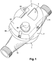
- the figure 1 represents a fluid meter, in particular water, according to the invention.
- This meter comprises a tank 1 with a water inlet pipe 1A and a water outlet pipe 1B, containing a measuring chamber, a totalizer covered with a so-called cover cap 2 and provided with an index 2A of consumption and a remote reading module 3 fixed to the front face of said cover and intended for remote reading of consumption and containing in a housing reading means and transmission means, this housing comprising a front wall and a wall lateral.
- This module 3, invisible on the figure 1 is covered by a cover 4, made of opaque material, arranged on the housing of the remote reading module, comprising a covering wall 4A of the front wall of the module, also covering the entire side wall of the module by its side wall 4B and secured to the cap 2 of the totalizer.
- a cover 4 made of opaque material, arranged on the housing of the remote reading module, comprising a covering wall 4A of the front wall of the module, also covering the entire side wall of the module by its side wall 4B and secured to the cap 2 of the totalizer.
- the cover 4 almost completely hides the remote reading module, so that an uninformed person does not know directly that a module is placed on the totalizer of the counter and above all does not see its fixing means.
- the figures 2 and 3 represent the same meter with the cover not fitted or in the process of being fitted.
- the housing of the remote reading module 3 has on its front wall 3A printed data specific to the module, for example a bar code, and a prominent chimney 3B containing the antenna of the module.
- the cover 4 includes an orifice 4C for passing this chimney 3B and, preferably, it also includes a window 4D for viewing the data printed on the module housing.
- the cover 4 covering the consumption index 2A of the totalizer also comprises a window 4E for viewing this index.
- the module 3 or rather its box is therefore visible through the orifice 4C for the passage of the chimney 3B and through the display window 4D of the printed data, the cover 2 of the totalizer, the box of the remote reading module 3 and the cover 4 are advantageously identical in color, in order to ensure the sought-after function of this module as much as possible.
- the meter fitted with the cover as shown in figure 1 seems to the untrained eye to consist of a single unit mounted on the tarpaulin 1.
- the cover 4 is preferably secured to the cover 2 of the totalizer by clipping.
- These clips are arranged on flanges 7 shaped on the cover 4 and intended to be received in recessed locations 8 shaped on the front face of the cover 2, in order to ensure a correct interface.
- these clips 5 cooperate with the four corresponding orifices 6 by displacement perpendicular to the front wall 3A.
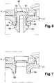
- these clips 5 also ensure the sealing against fraud, of this cover. As visible on the figures 4 to 7 , to do this they have rupture zones ensuring their detachment and, preferably, they can be detached by an impact perpendicular to the front wall 3A of the module, for example using a hammer.
- these clips 5 include a double harpoon snap-fit arrangement 5A, 5B intended to hook onto a rib 6A, 6B behind the cap 2, once introduced into the orifices 6.
- this double harpoon arrangement 5A, 5B the latter is connected to the cover 4 by thinned walls 5C, 5D forming break zones around a base 5E formed in the cover 4 and connecting the harpoons.
- the installer gives a shock, for example using a hammer, on this base 5E of the harpoons and shears the rupture zones, which results in the detachment of the double harpoon arrangement 5A, 5B and its fall inside the cover 2, between the latter and the totalizer.
- the cover 4 can then be removed and if necessary replaced.
Landscapes
- Physics & Mathematics (AREA)
- Fluid Mechanics (AREA)
- General Physics & Mathematics (AREA)
- Measuring Volume Flow (AREA)
Description
- L'invention se rapporte à un compteur de fluide, en particulier d'eau, équipé d'un module de télé-relevé disposé sur le capot de ce dernier.
-
KR 2009 0009151 U -
DE 102 14 418 A1 décrit un compteur de volume pour mesurer un volume de fluide, en particulier un compteur d'eau. -
EP 1 965 175 A2 décrit un compteur d'eau avec des moyens pour enregistrer numériquement les données de lecture et des moyens pour transmettre les données de lecture. -
DE 296 03 056 U1 décrit un débitmètre pour fluides. -
CN 2 655 194 Y décrit un compteur d'eau à distance sans fil. - Un tel module de télé-relevé est destiné au relevé à distance de la consommation et est installé sur des compteurs éventuellement déjà installés. Pour ce faire, il est appliqué sur la face supérieure du boîtier du totalisateur, afin d'assurer un positionnement précis de l'agencement de lecture du module par rapport à un agencement interne au totalisateur et permettant la détection de la consommation, par exemple le disque indicateur. Cette détection peut être effectuée de façon optique, capacitive, inductive ou autre, par exemple en scrutant le déplacement du disque indicateur.
- Il est connu, comme décrit dans le document de brevet
EP 1 586 869 ouEP 2 141 465 , de réaliser la fixation d'un tel module de télé-relevé sur le capot d'un compteur de fluide par l'intermédiaire d'un élément mâle fileté, de type vis, traversant le module et coopérant avec un insert femelle taraudé surmoulé dans le boîtier ou coiffe du totalisateur du compteur et destiné à recevoir l'élément mâle par vissage. - Dans un tel agencement, un dispositif de plombage à effet visuel peut être inséré à force dans une cavité conformée dans le boîtier du module et entourant la tête de la vis. Ce dispositif de plombage est une pièce ronde de matière plastique souple qui est encastrée dans la cavité, qui recouvre la tête de la vis et qui ne peut être enlevée, par exemple au moyen d'un tournevis, qu'avec sa destruction au moins partielle, ce qui permet de détecter visuellement l'enlèvement du module ou la fraude.
- Cet agencement peut également permettre de détecter à distance l'enlèvement du module de télé-relevé en équipant le dispositif de plombage d'un agencement de détection à distance de son positionnement et de son enlèvement.
- Ceci étant, un tel agencement laisse totalement visible le module de télé-relevé, le dispositif de plombage recouvrant la tête de la vis et, une fois ce dernier démonté, la tête de vis. Un fraudeur peut donc facilement être incité à démonter le module par enlèvement de ce dispositif de plombage et de la vis ou même à arracher le module de télé-relevé.
- Pour résoudre ce problème, l'invention propose d'équiper un tel compteur d'un capot disposé sur le boîtier du module de télé-relevé et comportant une paroi de recouvrement de sa paroi frontale.
- Il est par ailleurs décrit dans le document de brevet
WO 2009/121723 un module de télé-relevé destiné au relevé à distance de la consommation d'un compteur et comprenant un boîtier avec une paroi frontale et une paroi latérale. Ce module comprend également un capot de protection du rayonnement solaire spécifique, disposé sur le boîtier du module de télé-relevé et comportant au moins une paroi de recouvrement de ladite paroi frontale, ce capot pouvant être clippé sur le boîtier du module de télé-relevé. Ce capot peut comporter également un rebord périphérique recouvrant au moins partiellement la paroi latérale du module de télé-relevé. - Spécifiquement destiné à la protection au rayonnement solaire, ce rebord périphérique recouvre de préférence partiellement la paroi latérale du module de télé-relevé et ce capot comporte des moyens de circulation d'air entre le module de télé-relevé et le capot et, de préférence, des orifices d'aération dans sa paroi de recouvrement.
- Bien que concernant également un capot de recouvrement du module de télé-relevé, l'objet de l'invention est tout autre. Cet objet est de cacher totalement le module de télé-relevé, afin qu'une personne non avertie ne sache pas directement qu'un module est disposé sur le totalisateur du compteur et surtout ne voit pas ses moyens de fixation. Equipé de ce capot, le compteur se présente comme d'une seule pièce, non démontable.
- Pour ce faire, l'invention propose un compteur de fluide, en particulier d'eau, comportant un totalisateur pourvu d'un index de consommation, un boîtier dite coiffe recouvrant le totalisateur et un module de télé-relevé fixé sur la face frontale de ladite coiffe, destiné au relevé à distance de la consommation et contenant dans un boîtier des moyens de lecture et des moyens de transmission, ce boîtier comprenant une paroi frontale et une paroi latérale, ce module étant couvert par un capot, disposé sur le boîtier du module de télé-relevé et comportant au moins une paroi de recouvrement de ladite paroi frontale, compteur caractérisé en ce que ledit capot est en matériau opaque et recouvre également toute la dite paroi latérale du module et est solidarisé à ladite coiffe du totalisateur.
- Selon un mode de réalisation préféré, dont ledit module de télé-relevé comporte une cheminée proéminente contenant son antenne, ledit capot comporte un orifice de passage de ladite cheminée.
- De préférence, ledit capot comportant une fenêtre de visualisation de l'index de consommation dudit totalisateur.
- Ledit capot peut comporter également une fenêtre de visualisation de données imprimées sur le boîtier du module.
- Avantageusement, ladite coiffe du totalisateur, le boîtier dudit module de télé-relevé et ledit capot sont de couleur identique.
- De préférence, ledit capot est solidarisé à ladite coiffe du totalisateur par clippage.
- Ledit capot est avantageusement solidarisé à ladite coiffe du totalisateur au moyen d'au moins deux clips coopérant avec deux orifices correspondants agencés dans ladite coiffe du totalisateur.
- Ces clips coopèrent de préférence avec lesdits deux orifices correspondants par déplacement perpendiculaire à ladite paroi frontale.
- Lesdits clips présentent par ailleurs avantageusement des zones de rupture assurant leur détachement et, de préférence, lesdits clips peuvent être détachés par un choc perpendiculaire à ladite paroi frontale, par exemple à l'aide d'un marteau.
- L'invention est décrite ci-après plus en détail à l'aide de figures ne représentant qu'un mode de réalisation préférée de l'invention.
- La
figure 1 est une vue en perspective d'un compteur conforme à l'invention. - La
figure 2 est une vue en perspective d'un compteur conforme à l'invention, avant montage d'un capot. - La
figure 3 est une vue en perspective d'un compteur conforme à l'invention, lors du montage d'un capot. - Les
figures 4 à 7 sont des vues en coupe verticale de détail. - La
figure 1 représente un compteur de fluide, en particulier d'eau, conforme à l'invention. - Ce compteur comporte une bâche 1 avec une conduite d'entrée d'eau 1A et une conduite de sortie d'eau 1B, contenant une chambre de mesure, un totalisateur recouvert d'un capot dite coiffe 2 et pourvu d'un index 2A de consommation et un module de télé-relevé 3 fixé sur la face frontale de ladite coiffe et destiné au relevé à distance de la consommation et contenant dans un boîtier des moyens de lecture et des moyens de transmission, ce boîtier comprenant une paroi frontale et une paroi latérale.
- Ce module 3, invisible sur la
figure 1 , est couvert par un capot 4, en matériau opaque, disposé sur le boîtier du module de télé-relevé, comportant une paroi de recouvrement 4A de la paroi frontale du module, recouvrant également toute la paroi latérale du module par sa paroi latérale 4B et solidarisé à la coiffe 2 du totalisateur. - Ainsi équipé, le capot 4 cache quasi-totalement le module de télé-relevé, afin qu'une personne non avertie ne sache pas directement qu'un module est disposé sur le totalisateur du compteur et surtout ne voit pas ses moyens de fixation.
- Les
figures 2 et3 représentent ce même compteur avec le capot non monté ou en cours de montage. - Le boîtier du module de télé-relevé 3 présente sur sa paroi frontale 3A des données imprimées spécifiques au module, par exemple un code-barres, et une cheminée 3B proéminente contenant l'antenne du module.
- Afin d'assurer une bonne transmission de cette antenne, le capot 4 comporte un orifice 4C de passage de cette cheminée 3B et, de préférence, il comporte également une fenêtre 4D de visualisation des données imprimées sur le boîtier du module.
- Selon ce mode de réalisation, le capot 4 recouvrant l'index de consommation 2A du totaliseur, le capot 4 comporte également une fenêtre 4E de visualisation de cet index.
- Le module 3 ou plutôt son boîtier étant donc visible au travers de l'orifice 4C de passage de la cheminée 3B et au travers de la fenêtre 4D de visualisation des données imprimées, la coiffe 2 du totalisateur, le boîtier du module de télé-relevé 3 et le capot 4 sont avantageusement de couleur identique, afin d'assurer au maximum la fonction recherchée de cache de ce module. En d'autres termes, le compteur équipé du capot comme illustré sur la
figure 1 semble à l'œil non averti constitué d'une seule unité montée sur la bâche 1. - Le capot 4 est de préférence solidarisé à la coiffe 2 du totalisateur par clippage.
- Pour ce faire, il est avantageusement solidarisé à la coiffe 2 du totalisateur au moyen d'au moins deux clips 5 coopérant avec deux orifices 6 correspondants agencés dans la coiffe 2 du totalisateur. Dans l'exemple représenté, ces clips 5 et ces orifices 6 sont au nombre de quatre.
- Ces clips sont disposés sur des rebords 7 conformés sur le capot 4 et destinés à être reçus dans des emplacements d'encastrement 8 conformées sur la face frontale de la coiffe 2, afin d'assurer une interface correcte.
- Selon l'exemple représenté, ces clips 5 coopèrent avec les quatre orifices 6 correspondants par déplacement perpendiculaire à la paroi frontale 3A.
- Le démontage du capot 4 étant nécessaire en cas d'intervention par un installateur, ces clips 5 assurent également le plombage contre la fraude, de ce capot. Comme visibles sur les
figures 4 à 7 , ils présentent pour ce faire des zones de rupture assurant leur détachement et, de préférence, ils peuvent être détachés par un choc perpendiculaire à la paroi frontale 3A du module, par exemple à l'aide d'un marteau. - Comme bien visible sur les
figures 5 et6 , ces clips 5 comportent un agencement d'encliquetage à double harpon 5A, 5B destiné à venir s'accrocher sur une nervure 6A, 6B derrière la coiffe 2, une fois introduit dans les orifices 6. - A la base de cet agencement à double harpon 5A, 5B, ce dernier est relié au capot 4 par des parois amincies 5C, 5D formant des zones de rupture autour d'une base 5E formée dans le capot 4 et reliant les harpons. Si nécessaire, l'installateur donne un choc, par exemple à l'aide d'un marteau, sur cette base 5E des harpons et cisaille les zones de rupture, ce qui entraîne le détachement de l'agencement à double harpon 5A, 5B et sa tombée à l'intérieur de la coiffe 2, entre cette dernière et le totalisateur. Le capot 4 peut alors être enlevé et si besoin remplacé. Ces clips 5 assurent donc également le plombage contre la fraude, en cas d'une telle opération par un fraudeur.
Claims (10)
- Compteur de fluide, en particulier d'eau, comportant un totalisateur pourvu d'un index de consommation, un boîtier dite coiffe (2) recouvrant le totalisateur et un module de télé-relevé (3) fixé sur la face frontale de ladite coiffe, destiné au relevé à distance de la consommation et contenant dans un boîtier des moyens de lecture et des moyens de transmission, ce boîtier comprenant une paroi frontale (3A) et une paroi latérale (3C), ce module étant couvert par un capot (4), disposé sur le boîtier du module de télé-relevé et comportant au moins une paroi de recouvrement (4A) de ladite paroi frontale (3A), compteur caractérisé en ce que ledit capot (4) est en matériau opaque et recouvre également toute la dite paroi latérale (3C) du module et est solidarisé à ladite coiffe (2) du totalisateur.
- Compteur selon la revendication 1, dont ledit module de télé-relevé (3) comporte une cheminée proéminente (3B) contenant son antenne, caractérisé en ce que ledit capot (4) comporte un orifice (4C) de passage de ladite cheminée.
- Compteur selon l'une des revendications précédentes, caractérisé en ce que ledit capot (4) comporte une fenêtre (4E) de visualisation de l'index de consommation dudit totalisateur
- Compteur selon l'une des revendications précédentes, caractérisé en ce que ledit capot (4) comporte une fenêtre (4D) de visualisation de données imprimées sur le boîtier du module (3).
- Compteur selon l'une des revendications précédentes, caractérisé en ce que ladite coiffe (2) du totalisateur, le boîtier dudit module de télé-relevé (3) et ledit capot (4) sont de couleur identique.
- Compteur selon l'une des revendications précédentes, caractérisé en ce que ledit capot (4) est solidarisé à ladite coiffe (2) du totalisateur par clippage.
- Compteur selon la revendication précédente, caractérisé en ce que ledit capot (4) est solidarisé à ladite coiffe (2) du totalisateur au moyen d'au moins deux clips (5) coopérant avec deux orifices (6) correspondants agencés dans ladite coiffe (2) du totalisateur.
- Compteur selon la revendication précédente, caractérisé en ce que lesdits clips (5) sont configurés pour coopérer avec lesdits deux orifices (6) correspondants par déplacement perpendiculaire à ladite paroi frontale (3A).
- Compteur selon la revendication 7 ou 8, caractérisé en ce que lesdits clips (5) présentent des zones de rupture (5C, 5D) assurant leur détachement.
- Compteur selon la revendication précédente, caractérisé en ce que lesdits clips (5) sont configurés pour être détachés par un choc perpendiculaire à ladite paroi frontale (3A), par exemple à l'aide d'un marteau.
Priority Applications (1)
| Application Number | Priority Date | Filing Date | Title |
|---|---|---|---|
| EP11738236.6A EP2609404B1 (fr) | 2010-08-23 | 2011-08-02 | Compteur de fluide, en particulier d'eau, equipe d'un module de tele-releve |
Applications Claiming Priority (3)
| Application Number | Priority Date | Filing Date | Title |
|---|---|---|---|
| EP10305906 | 2010-08-23 | ||
| PCT/EP2011/063257 WO2012025340A1 (fr) | 2010-08-23 | 2011-08-02 | Compteur de fluide, en particulier d'eau, equipe d'un module de tele-releve |
| EP11738236.6A EP2609404B1 (fr) | 2010-08-23 | 2011-08-02 | Compteur de fluide, en particulier d'eau, equipe d'un module de tele-releve |
Publications (2)
| Publication Number | Publication Date |
|---|---|
| EP2609404A1 EP2609404A1 (fr) | 2013-07-03 |
| EP2609404B1 true EP2609404B1 (fr) | 2020-09-23 |
Family
ID=43480820
Family Applications (1)
| Application Number | Title | Priority Date | Filing Date |
|---|---|---|---|
| EP11738236.6A Active EP2609404B1 (fr) | 2010-08-23 | 2011-08-02 | Compteur de fluide, en particulier d'eau, equipe d'un module de tele-releve |
Country Status (4)
| Country | Link |
|---|---|
| EP (1) | EP2609404B1 (fr) |
| CN (1) | CN103180696A (fr) |
| WO (1) | WO2012025340A1 (fr) |
| ZA (1) | ZA201302063B (fr) |
Families Citing this family (3)
| Publication number | Priority date | Publication date | Assignee | Title |
|---|---|---|---|---|
| EP3260819B1 (fr) | 2016-06-23 | 2018-10-17 | Aiut Sp. z o.o. | Extension de compteur d'eau |
| CN111174847B (zh) * | 2018-11-09 | 2021-09-07 | 群光电子股份有限公司 | 计量表辅助模块 |
| DE102022131437A1 (de) * | 2022-11-28 | 2024-05-29 | Landis + Gyr Gmbh | Gehäuse zum Umschliessen eines Messteils eines Flüssigkeitsdurchflussmessers |
Family Cites Families (9)
| Publication number | Priority date | Publication date | Assignee | Title |
|---|---|---|---|---|
| GB1581211A (en) * | 1978-01-05 | 1980-12-10 | Kromschroeder Ag G | Sealing devices |
| DE29603056U1 (de) * | 1996-02-21 | 1996-05-09 | Minol Messtechnik W. Lehmann GmbH & Co, 70771 Leinfelden-Echterdingen | Durchflußzähler für Flüssigkeiten |
| DE10214418A1 (de) * | 2002-03-30 | 2003-10-09 | Abb Patent Gmbh | Volumenzähler zum Messen eines Flüssigkeitsvolumens |
| CN2655194Y (zh) * | 2003-11-18 | 2004-11-10 | 庄革 | 无线远传水表 |
| FR2868530B1 (fr) | 2004-03-30 | 2006-05-26 | Actaris | Agencement destine a la fixation d'un dispositif sur le capot d'un compteur de fluide. |
| DE202007003276U1 (de) * | 2007-03-02 | 2007-05-03 | Zenner International Gmbh & Co. Kg | Wasserzähler |
| EP2107351A1 (fr) | 2008-04-02 | 2009-10-07 | Actaris SAS | Dispositif de télérelevé pour compteur |
| EP2141465A1 (fr) | 2008-07-01 | 2010-01-06 | Actaris SAS | Agencement de fixation d'un module de tele releve sur le capot d'un compteur de fluide |
| KR20090009151U (ko) * | 2009-07-09 | 2009-09-10 | 주식회사 이비 | 지침구 및 리스스위치 또는 카운터 및 리스스위치에 자성체가 장착된 자계 습식 원격검침계량기 |
-
2011
- 2011-08-02 CN CN2011800507186A patent/CN103180696A/zh active Pending
- 2011-08-02 EP EP11738236.6A patent/EP2609404B1/fr active Active
- 2011-08-02 WO PCT/EP2011/063257 patent/WO2012025340A1/fr not_active Ceased
-
2013
- 2013-03-19 ZA ZA2013/02063A patent/ZA201302063B/en unknown
Non-Patent Citations (1)
| Title |
|---|
| None * |
Also Published As
| Publication number | Publication date |
|---|---|
| CN103180696A (zh) | 2013-06-26 |
| EP2609404A1 (fr) | 2013-07-03 |
| ZA201302063B (en) | 2014-05-28 |
| WO2012025340A1 (fr) | 2012-03-01 |
Similar Documents
| Publication | Publication Date | Title |
|---|---|---|
| EP2579007B1 (fr) | Compteur de fluide, en particulier d'eau | |
| WO2012025340A1 (fr) | Compteur de fluide, en particulier d'eau, equipe d'un module de tele-releve | |
| WO2005089482A3 (fr) | Ensemble de remplissage de carburant avec receptacle de clapet anti-retour et prise de carburant remplaçable pour reservoirs de carburant a remplissage par le bas | |
| EP2141465A1 (fr) | Agencement de fixation d'un module de tele releve sur le capot d'un compteur de fluide | |
| EP2107351A1 (fr) | Dispositif de télérelevé pour compteur | |
| EP2579008A1 (fr) | Compteur de fluide, en particulier d'eau | |
| KR101935811B1 (ko) | 부정사용을 방지하기 위한 계량기의 봉인장치 | |
| EP1326061B1 (fr) | Compteur de liquides | |
| FR2522410A1 (fr) | Bouclier protecteur pour voyant de debimetre | |
| US20110097219A1 (en) | Ice water pump | |
| FR2966660A1 (fr) | Bouchon d'etancheite pour sortie de ventilation | |
| EP2295941B1 (fr) | Compteur de fluide équipé d'un module de télérelève fixé au moyen d'une bague anti-fraude | |
| FR3006966A1 (fr) | Support pour recipient de fluide lave-glace, recipient de fluide lave-glace et dispositif comprenant lesdits support et recipient | |
| EP2600123B1 (fr) | Compteur de fluide en particulier d'eau | |
| EP2604985B1 (fr) | Compteur de fluide, en particulier d'eau | |
| FR3032983B1 (fr) | Dispositif de collecte des eaux de ruissellement | |
| KR101611074B1 (ko) | 수도미터기 보호통 | |
| EP3674492B1 (fr) | Broyeur sanitaire immergeable | |
| WO2014106662A1 (fr) | Kit de rétrofit d'un compteur avec un dispositif de télérelève | |
| KR101223587B1 (ko) | 가스계량기용 보호커버 | |
| EP1586869A1 (fr) | Agencement destiné à la fixation d'un dispositif sur le capot d'un compteur de fluide | |
| JP2010019590A (ja) | 膜式ガスメータ | |
| EP0981676A1 (fr) | Dispositif immerge pour piscine | |
| FR3070160A1 (fr) | Piece instrumentalisable pour contenant | |
| EP2056077A1 (fr) | Compteur pourvu de moyens de detection de fraude ou de tentative de fraude |
Legal Events
| Date | Code | Title | Description |
|---|---|---|---|
| PUAI | Public reference made under article 153(3) epc to a published international application that has entered the european phase |
Free format text: ORIGINAL CODE: 0009012 |
|
| 17P | Request for examination filed |
Effective date: 20130322 |
|
| AK | Designated contracting states |
Kind code of ref document: A1 Designated state(s): AL AT BE BG CH CY CZ DE DK EE ES FI FR GB GR HR HU IE IS IT LI LT LU LV MC MK MT NL NO PL PT RO RS SE SI SK SM TR |
|
| RIN1 | Information on inventor provided before grant (corrected) |
Inventor name: CHAUDY, ALAIN Inventor name: BOUZID, TAREK Inventor name: CATHERIN, DANIEL |
|
| DAX | Request for extension of the european patent (deleted) | ||
| STAA | Information on the status of an ep patent application or granted ep patent |
Free format text: STATUS: EXAMINATION IS IN PROGRESS |
|
| 17Q | First examination report despatched |
Effective date: 20161111 |
|
| RAP1 | Party data changed (applicant data changed or rights of an application transferred) |
Owner name: ITRON GLOBAL SARL |
|
| GRAP | Despatch of communication of intention to grant a patent |
Free format text: ORIGINAL CODE: EPIDOSNIGR1 |
|
| STAA | Information on the status of an ep patent application or granted ep patent |
Free format text: STATUS: GRANT OF PATENT IS INTENDED |
|
| INTG | Intention to grant announced |
Effective date: 20200319 |
|
| GRAJ | Information related to disapproval of communication of intention to grant by the applicant or resumption of examination proceedings by the epo deleted |
Free format text: ORIGINAL CODE: EPIDOSDIGR1 |
|
| STAA | Information on the status of an ep patent application or granted ep patent |
Free format text: STATUS: EXAMINATION IS IN PROGRESS |
|
| GRAR | Information related to intention to grant a patent recorded |
Free format text: ORIGINAL CODE: EPIDOSNIGR71 |
|
| GRAS | Grant fee paid |
Free format text: ORIGINAL CODE: EPIDOSNIGR3 |
|
| STAA | Information on the status of an ep patent application or granted ep patent |
Free format text: STATUS: GRANT OF PATENT IS INTENDED |
|
| GRAA | (expected) grant |
Free format text: ORIGINAL CODE: 0009210 |
|
| STAA | Information on the status of an ep patent application or granted ep patent |
Free format text: STATUS: THE PATENT HAS BEEN GRANTED |
|
| INTC | Intention to grant announced (deleted) | ||
| INTG | Intention to grant announced |
Effective date: 20200811 |
|
| AK | Designated contracting states |
Kind code of ref document: B1 Designated state(s): AL AT BE BG CH CY CZ DE DK EE ES FI FR GB GR HR HU IE IS IT LI LT LU LV MC MK MT NL NO PL PT RO RS SE SI SK SM TR |
|
| REG | Reference to a national code |
Ref country code: GB Ref legal event code: FG4D Free format text: NOT ENGLISH |
|
| REG | Reference to a national code |
Ref country code: CH Ref legal event code: EP |
|
| REG | Reference to a national code |
Ref country code: DE Ref legal event code: R096 Ref document number: 602011068701 Country of ref document: DE |
|
| REG | Reference to a national code |
Ref country code: IE Ref legal event code: FG4D Free format text: LANGUAGE OF EP DOCUMENT: FRENCH |
|
| REG | Reference to a national code |
Ref country code: AT Ref legal event code: REF Ref document number: 1316866 Country of ref document: AT Kind code of ref document: T Effective date: 20201015 |
|
| PG25 | Lapsed in a contracting state [announced via postgrant information from national office to epo] |
Ref country code: BG Free format text: LAPSE BECAUSE OF FAILURE TO SUBMIT A TRANSLATION OF THE DESCRIPTION OR TO PAY THE FEE WITHIN THE PRESCRIBED TIME-LIMIT Effective date: 20201223 Ref country code: HR Free format text: LAPSE BECAUSE OF FAILURE TO SUBMIT A TRANSLATION OF THE DESCRIPTION OR TO PAY THE FEE WITHIN THE PRESCRIBED TIME-LIMIT Effective date: 20200923 Ref country code: NO Free format text: LAPSE BECAUSE OF FAILURE TO SUBMIT A TRANSLATION OF THE DESCRIPTION OR TO PAY THE FEE WITHIN THE PRESCRIBED TIME-LIMIT Effective date: 20201223 Ref country code: GR Free format text: LAPSE BECAUSE OF FAILURE TO SUBMIT A TRANSLATION OF THE DESCRIPTION OR TO PAY THE FEE WITHIN THE PRESCRIBED TIME-LIMIT Effective date: 20201224 Ref country code: FI Free format text: LAPSE BECAUSE OF FAILURE TO SUBMIT A TRANSLATION OF THE DESCRIPTION OR TO PAY THE FEE WITHIN THE PRESCRIBED TIME-LIMIT Effective date: 20200923 Ref country code: SE Free format text: LAPSE BECAUSE OF FAILURE TO SUBMIT A TRANSLATION OF THE DESCRIPTION OR TO PAY THE FEE WITHIN THE PRESCRIBED TIME-LIMIT Effective date: 20200923 |
|
| REG | Reference to a national code |
Ref country code: AT Ref legal event code: MK05 Ref document number: 1316866 Country of ref document: AT Kind code of ref document: T Effective date: 20200923 |
|
| PG25 | Lapsed in a contracting state [announced via postgrant information from national office to epo] |
Ref country code: RS Free format text: LAPSE BECAUSE OF FAILURE TO SUBMIT A TRANSLATION OF THE DESCRIPTION OR TO PAY THE FEE WITHIN THE PRESCRIBED TIME-LIMIT Effective date: 20200923 Ref country code: LV Free format text: LAPSE BECAUSE OF FAILURE TO SUBMIT A TRANSLATION OF THE DESCRIPTION OR TO PAY THE FEE WITHIN THE PRESCRIBED TIME-LIMIT Effective date: 20200923 |
|
| REG | Reference to a national code |
Ref country code: NL Ref legal event code: MP Effective date: 20200923 |
|
| REG | Reference to a national code |
Ref country code: LT Ref legal event code: MG4D |
|
| PG25 | Lapsed in a contracting state [announced via postgrant information from national office to epo] |
Ref country code: EE Free format text: LAPSE BECAUSE OF FAILURE TO SUBMIT A TRANSLATION OF THE DESCRIPTION OR TO PAY THE FEE WITHIN THE PRESCRIBED TIME-LIMIT Effective date: 20200923 Ref country code: CZ Free format text: LAPSE BECAUSE OF FAILURE TO SUBMIT A TRANSLATION OF THE DESCRIPTION OR TO PAY THE FEE WITHIN THE PRESCRIBED TIME-LIMIT Effective date: 20200923 Ref country code: NL Free format text: LAPSE BECAUSE OF FAILURE TO SUBMIT A TRANSLATION OF THE DESCRIPTION OR TO PAY THE FEE WITHIN THE PRESCRIBED TIME-LIMIT Effective date: 20200923 Ref country code: LT Free format text: LAPSE BECAUSE OF FAILURE TO SUBMIT A TRANSLATION OF THE DESCRIPTION OR TO PAY THE FEE WITHIN THE PRESCRIBED TIME-LIMIT Effective date: 20200923 Ref country code: PT Free format text: LAPSE BECAUSE OF FAILURE TO SUBMIT A TRANSLATION OF THE DESCRIPTION OR TO PAY THE FEE WITHIN THE PRESCRIBED TIME-LIMIT Effective date: 20210125 Ref country code: SM Free format text: LAPSE BECAUSE OF FAILURE TO SUBMIT A TRANSLATION OF THE DESCRIPTION OR TO PAY THE FEE WITHIN THE PRESCRIBED TIME-LIMIT Effective date: 20200923 Ref country code: RO Free format text: LAPSE BECAUSE OF FAILURE TO SUBMIT A TRANSLATION OF THE DESCRIPTION OR TO PAY THE FEE WITHIN THE PRESCRIBED TIME-LIMIT Effective date: 20200923 |
|
| PG25 | Lapsed in a contracting state [announced via postgrant information from national office to epo] |
Ref country code: AT Free format text: LAPSE BECAUSE OF FAILURE TO SUBMIT A TRANSLATION OF THE DESCRIPTION OR TO PAY THE FEE WITHIN THE PRESCRIBED TIME-LIMIT Effective date: 20200923 Ref country code: AL Free format text: LAPSE BECAUSE OF FAILURE TO SUBMIT A TRANSLATION OF THE DESCRIPTION OR TO PAY THE FEE WITHIN THE PRESCRIBED TIME-LIMIT Effective date: 20200923 Ref country code: ES Free format text: LAPSE BECAUSE OF FAILURE TO SUBMIT A TRANSLATION OF THE DESCRIPTION OR TO PAY THE FEE WITHIN THE PRESCRIBED TIME-LIMIT Effective date: 20200923 Ref country code: IS Free format text: LAPSE BECAUSE OF FAILURE TO SUBMIT A TRANSLATION OF THE DESCRIPTION OR TO PAY THE FEE WITHIN THE PRESCRIBED TIME-LIMIT Effective date: 20210123 Ref country code: PL Free format text: LAPSE BECAUSE OF FAILURE TO SUBMIT A TRANSLATION OF THE DESCRIPTION OR TO PAY THE FEE WITHIN THE PRESCRIBED TIME-LIMIT Effective date: 20200923 |
|
| REG | Reference to a national code |
Ref country code: DE Ref legal event code: R097 Ref document number: 602011068701 Country of ref document: DE |
|
| PG25 | Lapsed in a contracting state [announced via postgrant information from national office to epo] |
Ref country code: SK Free format text: LAPSE BECAUSE OF FAILURE TO SUBMIT A TRANSLATION OF THE DESCRIPTION OR TO PAY THE FEE WITHIN THE PRESCRIBED TIME-LIMIT Effective date: 20200923 |
|
| PLBE | No opposition filed within time limit |
Free format text: ORIGINAL CODE: 0009261 |
|
| STAA | Information on the status of an ep patent application or granted ep patent |
Free format text: STATUS: NO OPPOSITION FILED WITHIN TIME LIMIT |
|
| PG25 | Lapsed in a contracting state [announced via postgrant information from national office to epo] |
Ref country code: DK Free format text: LAPSE BECAUSE OF FAILURE TO SUBMIT A TRANSLATION OF THE DESCRIPTION OR TO PAY THE FEE WITHIN THE PRESCRIBED TIME-LIMIT Effective date: 20200923 Ref country code: SI Free format text: LAPSE BECAUSE OF FAILURE TO SUBMIT A TRANSLATION OF THE DESCRIPTION OR TO PAY THE FEE WITHIN THE PRESCRIBED TIME-LIMIT Effective date: 20200923 |
|
| 26N | No opposition filed |
Effective date: 20210624 |
|
| PG25 | Lapsed in a contracting state [announced via postgrant information from national office to epo] |
Ref country code: IT Free format text: LAPSE BECAUSE OF FAILURE TO SUBMIT A TRANSLATION OF THE DESCRIPTION OR TO PAY THE FEE WITHIN THE PRESCRIBED TIME-LIMIT Effective date: 20200923 |
|
| REG | Reference to a national code |
Ref country code: CH Ref legal event code: PL |
|
| PG25 | Lapsed in a contracting state [announced via postgrant information from national office to epo] |
Ref country code: MC Free format text: LAPSE BECAUSE OF FAILURE TO SUBMIT A TRANSLATION OF THE DESCRIPTION OR TO PAY THE FEE WITHIN THE PRESCRIBED TIME-LIMIT Effective date: 20200923 |
|
| REG | Reference to a national code |
Ref country code: BE Ref legal event code: MM Effective date: 20210831 |
|
| PG25 | Lapsed in a contracting state [announced via postgrant information from national office to epo] |
Ref country code: LI Free format text: LAPSE BECAUSE OF NON-PAYMENT OF DUE FEES Effective date: 20210831 Ref country code: CH Free format text: LAPSE BECAUSE OF NON-PAYMENT OF DUE FEES Effective date: 20210831 |
|
| PG25 | Lapsed in a contracting state [announced via postgrant information from national office to epo] |
Ref country code: LU Free format text: LAPSE BECAUSE OF NON-PAYMENT OF DUE FEES Effective date: 20210802 |
|
| PG25 | Lapsed in a contracting state [announced via postgrant information from national office to epo] |
Ref country code: IE Free format text: LAPSE BECAUSE OF NON-PAYMENT OF DUE FEES Effective date: 20210802 Ref country code: BE Free format text: LAPSE BECAUSE OF NON-PAYMENT OF DUE FEES Effective date: 20210831 |
|
| PG25 | Lapsed in a contracting state [announced via postgrant information from national office to epo] |
Ref country code: HU Free format text: LAPSE BECAUSE OF FAILURE TO SUBMIT A TRANSLATION OF THE DESCRIPTION OR TO PAY THE FEE WITHIN THE PRESCRIBED TIME-LIMIT; INVALID AB INITIO Effective date: 20110802 Ref country code: CY Free format text: LAPSE BECAUSE OF FAILURE TO SUBMIT A TRANSLATION OF THE DESCRIPTION OR TO PAY THE FEE WITHIN THE PRESCRIBED TIME-LIMIT Effective date: 20200923 |
|
| P01 | Opt-out of the competence of the unified patent court (upc) registered |
Effective date: 20230519 |
|
| PG25 | Lapsed in a contracting state [announced via postgrant information from national office to epo] |
Ref country code: MK Free format text: LAPSE BECAUSE OF FAILURE TO SUBMIT A TRANSLATION OF THE DESCRIPTION OR TO PAY THE FEE WITHIN THE PRESCRIBED TIME-LIMIT Effective date: 20200923 |
|
| PG25 | Lapsed in a contracting state [announced via postgrant information from national office to epo] |
Ref country code: MT Free format text: LAPSE BECAUSE OF FAILURE TO SUBMIT A TRANSLATION OF THE DESCRIPTION OR TO PAY THE FEE WITHIN THE PRESCRIBED TIME-LIMIT Effective date: 20200923 |
|
| PGFP | Annual fee paid to national office [announced via postgrant information from national office to epo] |
Ref country code: GB Payment date: 20250612 Year of fee payment: 15 |
|
| PGFP | Annual fee paid to national office [announced via postgrant information from national office to epo] |
Ref country code: FR Payment date: 20250610 Year of fee payment: 15 |
|
| PGFP | Annual fee paid to national office [announced via postgrant information from national office to epo] |
Ref country code: DE Payment date: 20250611 Year of fee payment: 15 |
|
| PG25 | Lapsed in a contracting state [announced via postgrant information from national office to epo] |
Ref country code: TR Free format text: LAPSE BECAUSE OF FAILURE TO SUBMIT A TRANSLATION OF THE DESCRIPTION OR TO PAY THE FEE WITHIN THE PRESCRIBED TIME-LIMIT Effective date: 20200923 |