EP2608608A1 - Maintaining signaling reduction mode in communication networks - Google Patents
Maintaining signaling reduction mode in communication networks Download PDFInfo
- Publication number
- EP2608608A1 EP2608608A1 EP12169626.4A EP12169626A EP2608608A1 EP 2608608 A1 EP2608608 A1 EP 2608608A1 EP 12169626 A EP12169626 A EP 12169626A EP 2608608 A1 EP2608608 A1 EP 2608608A1
- Authority
- EP
- European Patent Office
- Prior art keywords
- wireless access
- access node
- mme
- sgsn
- sgw
- Prior art date
- Legal status (The legal status is an assumption and is not a legal conclusion. Google has not performed a legal analysis and makes no representation as to the accuracy of the status listed.)
- Granted
Links
Images


Classifications
-
- H—ELECTRICITY
- H04—ELECTRIC COMMUNICATION TECHNIQUE
- H04W—WIRELESS COMMUNICATION NETWORKS
- H04W60/00—Affiliation to network, e.g. registration; Terminating affiliation with the network, e.g. de-registration
-
- H—ELECTRICITY
- H04—ELECTRIC COMMUNICATION TECHNIQUE
- H04W—WIRELESS COMMUNICATION NETWORKS
- H04W48/00—Access restriction; Network selection; Access point selection
- H04W48/08—Access restriction or access information delivery, e.g. discovery data delivery
- H04W48/12—Access restriction or access information delivery, e.g. discovery data delivery using downlink control channel
Definitions
- the present disclosure relates generally to a system and method for providing a persistent signaling reduction mode within a telecommunications network.
- Wireless networks are telecommunications networks that use radio waves to carry information from one node in the network to one or more receiving nodes in the network.
- Cellular telephony is characterized by the use of radio cells that provide radio coverage for a geographic area, with multiple cells arranged to provide contiguous radio coverage over a larger area.
- Wired communication can also be used in portions of a wireless network, such as between cells or access points.
- Wireless communication technologies are used in connection with many applications, including, for example, satellite communications systems, portable digital assistants (PDAs), laptop computers, and mobile devices (e.g., cellular telephones, user equipment). Users of such applications can connect to a network (e.g., the Internet) as long as the user is within range of such a wireless communication technology.
- a network e.g., the Internet
- Each wireless communication technology has a corresponding radio access technology.
- network connectivity is achieved through a combination of radio access technologies.
- a mobile device As a new generation of radio access technologies are made available in an area, a mobile device is likely to receive a mix of service from a new generation radio access technology (e.g., E-UTRAN) and a previous generation radio access technologies (e.g., GERAN / UTRAN), switching between them often.
- the Idle state Signaling Reduction (ISR) mode once activated, allows a mobile device to reselect between available radio access technologies with reduced radio signaling.
- ISR Idle state Signaling Reduction
- FIG. 1 illustrates a communications network in accordance with some embodiments
- FIG. 2A is a message diagram illustrating idle mode signaling reduction activation
- FIG. 2B is a message diagram illustrating idle mode signaling reduction activation in accordance with some embodiments.
- FIGS. 3A , 4A , 5A , 6A , 7A , and 8A are message diagrams illustrating idle mode signaling reduction deactivation
- FIGS. 3B , 4B , 5B , 6B , 7B , and 8B are message diagrams illustrating idle mode signaling reduction continuation in accordance with some embodiments
- FIG. 9 illustrates a logical view of a wireless access node in accordance with some embodiments.
- FIG. 10 illustrates a network device in accordance with some embodiments.
- FIG. 11 illustrates a logical view of the software architecture of a network device in accordance with some embodiments.
- Certain embodiments disclose a method comprising activating a signaling reduction mode on a wireless access node for a mobile device in an idle state where the signaling reduction mode permits the mobile device to switch radio access technologies while maintaining registration with both the wireless access node and a peer wireless access node, exchanging with the peer wireless access node a first control tunnel identifier of the wireless access node and a second control tunnel identifier of the peer wireless access node, selecting at the wireless access node a second gateway to replace a first gateway, establishing a control connection with the second gateway, transmitting to the second gateway the second control tunnel identifier of the peer wireless access node so that the second gateway may establish a control connection with the peer wireless access node, and continuing the signaling reduction mode.
- This disclosure relates generally to maintaining a signaling reduction mode for mobile devices in a communication network.
- Mobile devices such as smartphones, cell phones, and data-cards have continued to proliferate at a rapid pace.
- the networks that serve these devices have continued to evolve. New generations of networks provide faster connections, increased reliability and improved user experiences.
- the deployment of these new networks often involves extensive rollout of new hardware that is achieved in phases of gradually increasing geographic scope.
- the network coverage available to mobile device users may be a mixture of old and new technologies. Users in these areas are likely to make use of several generations of technology and to transition between them frequently. Network handover procedures can make these transitions seamless to users.
- Network handover procedures allow a mobile device to maintain its network registration while roaming within the network. For example, a network handover procedure may occur when a user with a mobile device moves out of the range of one wireless transceiver and into the range of a new wireless transceiver that is part of the same network. The handover procedure may be initiated when the new transceiver receives a location update request message from the mobile device. This location update message indicates that the mobile device is requesting service from the new transceiver. In response, the nodes of the network exchange the information that is used to reconfigure the network and begin serving the mobile device from the new transceiver.
- Idle mode signaling reduction is a signaling reduction mode that, once activated, reduces resource-intensive radio signaling during an inter-radio access technology handover. This disclosure describes some embodiments that continue ISR activation on certain categories of network handovers.
- ISR works in areas that are served by both a GSM EDGE Radio Access Network (GERAN) or a UMTS Terrestrial Radio Access Network (UTRAN) and an evolved UMTS Terrestrial Radio Access Network (E-UTRAN).
- GERAN GSM EDGE Radio Access Network
- UTRAN UMTS Terrestrial Radio Access Network
- E-UTRAN evolved UMTS Terrestrial Radio Access Network
- ISR once activated, reduces the radio signaling that occurs during an inter-radio access technology handover between the GERAN / UTRAN radio access technology and the E-UTRAN radio access technology.
- a mobile device registers with a network through an initial attach procedure. ISR activation occurs, for example, when a mobile device already registered, or attached, using E-UTRAN roams into the range of a transceiver or base station using GERAN / UTRAN.
- ISR is activated during the subsequent handover procedure run through GERAN / UTRAN. Once activated, ISR allows the mobile device to be simultaneously registered through both E-UTRAN and GERAN / UTRAN. A device that is simultaneously registered with both types of networks can reselect between them without re-registering. As such, a mobile device with ISR activated can roam freely between E-UTRAN and GERAN / UTRAN radio access technologies without the need to re-register. Network registration is a procedure that expends device battery life and network resources.
- Both the E-UTRAN and GERAN / UTRAN radio access technologies interact with a wireless access network to provide network services.
- this wireless access network contains nodes used to interface, control, and carry traffic on behalf of both base stations using both radio access technologies.
- a mobile device registers with the access network and specifically with an access node to receive network services using a radio access technology.
- the access node includes network equipment in the access or core network that provide services to one or more mobile devices.
- the access node can be, for example, an MME, an SGSN, an SGW, a PGW, a PCRF, a GGSN, a PDSN, or any other applicable network device.
- the access node in some embodiments may include one or more of these functionalities.
- the wireless access nodes exchange the information used to maintain parallel mobile device registration through both radio access technologies.
- a mobile device may move within a network once registered.
- new access nodes may be swapped with previously used access nodes to better serve the mobile device at its new location.
- These access nodes may also be swapped during a network handover procedure.
- the state stored during ISR activation is lost when access nodes are swapped. Thus, ISR is deactivated in these cases.
- This disclosure describes some embodiments where ISR activation is continued even when a network handover causes an access node to be swapped.
- ISR is an important mechanism to reduce the amount of wireless signaling sent to and from mobile devices that frequently reselect between E-UTRAN and GERAN / UTRAN radio access technologies. This reduction in signaling saves mobile device battery life and reduces load on the wireless spectrum. Thus, it is important to continue ISR activation even upon network handovers that cause an access node to be swapped.
- This disclosure describes some embodiments where the wireless access network nodes can distribute and store information during ISR activation to enable ISR continuation in the case of such a swap. This disclosure also describes embodiments where the wireless access network uses this stored information during such a swap to update the swapped-in access node with the information stored by the swapped-out access node.
- the swapped-in node is able to continue ISR in place of the swapped-out node because of the stored information.
- Signaling reduction modes other than ISR, and mobile device selection between radio access technologies other than E-UTRAN and GERAN / UTRAN are other embodiments.
- FIG. 1 illustrates a network diagram in accordance with certain embodiments.
- FIG. 1 illustrates a universal mobile telecommunication system (UMTS) network along with a LTE network.
- the network diagram of FIG. 1 includes user equipment (UE) 110, an evolved nodeB (eNB) 112, a nodeB (NB) 114, a radio network controller (RNC) 116, a mobility management entity (MME) or user plane entity (UPE) 118, a system architecture evolution gateway (SAE GW) 120, a policy and charging rules function (PCRF) 122, home subscriber server (HSS) 124, core IP network 126, internet 128, Serving General packet radio service Support Node (SGSN) 130, and network management system (NMS) / element management system (EMS) 132.
- UE user equipment
- eNB evolved nodeB
- NB nodeB
- RNC radio network controller
- MME mobility management entity
- UPE user plane entity
- SAE GW system architecture evolution gateway
- PCRF
- the MME 118, SGSN 130, and SAE GW 120 can be implemented in a gateway as described below.
- the SAE GW 120 can include a serving gateway (SGW) as well as a packet data network gateway (PGW). In some embodiments, the SGW and PGW can be implemented on separate network devices.
- the main component of the SAE architecture is the Evolved Packet Core (EPC), also known as SAE Core.
- the EPC includes the MME, SGW and PGW components.
- the user equipment (UE) can include a mobile phone, a laptop with wireless connectivity, a netbook, a smartphone, or any other wireless device.
- MME 118 is a control-node for the LTE access network.
- the MME 118 is responsible for UE 110 tracking and paging procedures including retransmissions.
- MME 118 handles the bearer activation/deactivation process and is also responsible for choosing the SGW for a UE 110 at the initial attach and at time of an intra-LTE handover.
- the MME 118 also authenticates the user by interacting with the HSS 124.
- the MME 118 also generates and allocates temporary identities to UEs and terminates Non-Access Stratum (NAS) signaling.
- the MME 118 checks the authorization of the UE 110 to camp on the service provider's Public Land Mobile Network (PLMN) and enforces UE roaming restrictions.
- PLMN Public Land Mobile Network
- the MME 118 is the termination point in the network for ciphering/integrity protection for NAS signaling and handles the security key management. Lawful interception of signaling is also supported by the MME 118.
- the MME also provides the control plane function for mobility between LTE and 2G/3G access networks with the S3 interface terminating at the MME 118 from the SGSN 130.
- the MME 118 also terminates the S6a interface towards the home HSS for roaming UEs.
- the MME 118, the SGSN 130 and the SAE GW 120 are all part of the wireless access network.
- the wireless access network provides network access to radio access networks.
- the radio access networks include the eNB 112 and the RNC 116 / NB 114.
- the SGW routes and forwards user data packets, while also acting as the mobility anchor for the user plane during inter-eNB handovers and as the anchor for mobility between LTE and other 3GPP technologies (terminating S4 interface and relaying the traffic between 2G/3G systems and PDN GW). For idle state UEs, the SGW terminates the down link data path and triggers paging when down link data arrives for the UE 110.
- the SGW manages and stores UE contexts, e.g., parameters of the IP bearer service and network internal routing information. The SGW also performs replication of the user traffic in case of lawful interception.
- the P-GW provides connectivity to the UE 110 to external packet data networks by being the point of exit and entry of traffic for the UE 110.
- a UE 110 may have simultaneous connectivity with more than one PGW for accessing multiple packet data networks.
- the PGW performs policy enforcement, packet filtering for each user, charging support, lawful interception, and packet screening.
- the PGW also provides an anchor for mobility between 3GPP and non-3GPP technologies such as WiMAX and 3GPP2 (CDMA 1X and EvDO).
- the NMS/EMS 132 can provide management of the operation, administration, maintenance, and provisioning of networked system. Operation deals with keeping the network (and the services that the network provides) up and running smoothly, and includes monitoring to detect problems and minimize disruptions on the network. Administration deals with keeping track of resources in the network and how they are assigned. Maintenance is concerned with performing repairs and upgrades - for example, when equipment must be replaced, when a router needs a patch for an operating system image, when a new switch is added to a network. Provisioning is concerned with configuring resources in the network to support a given service. For example, this might include setting up the network so that a new customer can receive service.
- Functions that are performed as part of network management accordingly include controlling, planning, allocating, deploying, coordinating, and monitoring the resources of a network, network planning, frequency allocation, predetermined traffic routing to support load balancing, cryptographic key distribution authorization, configuration management, fault management, security management, performance management, bandwidth management, and accounting management.
- An element management system consists of systems and applications that manage network elements (NE) on the network element management layer (NEL) of the Telecommunication Management Network model.
- the user equipment may be in an active or an idle state. Whether the UE is in an active state can depend on the state of a packet data session, and whether there is an active packet data session.
- the idle state is a sleep mode state that can be used to conserve battery life of user equipment by minimizing the need to power receivers to be ready for radio signals.
- the paging indicators are usually sent from a number of cells because user equipment may move while in an idle state.
- the SGW can buffer IP packets received for the user equipment and can initiate page requests towards the MME or SGSN.
- the SGW may initiate page requests towards both the MME and the SGSN. If the user equipment responds to the page, the SGW forwards the IP packet to the eNB in a LTE network or to a RNC/NB or SGSN in UMTS/general packet radio service (GPRS) for delivery to the user equipment.
- GPRS general packet radio service
- a UE first registers itself with an LTE network by initiating an Initial Attach procedure across E-UTRAN.
- the UE identifies itself to an E-UTRAN base station and requests to be served by the wireless access network.
- the HSS interacts with the MME to authenticate the user and approve the attach request.
- a connection may be established between the UE and the SGW for the transmission of traffic to a packet data network (PDN).
- PDN packet data network
- EPS Evolved Packet System
- EPS Bearer Activation a connection tunnel is established between the UE and the PGW to carry a particular type of data, such as a voice conversation or streaming video.
- This connection passes through the SGW to the PGW.
- Specific forwarding and quality-of-service parameters are also configured as appropriate for the type of data that is to be sent.
- the portion of the tunnel from the SGW to the UE is called an E-UTRAN Radio Access Bearer (E-RAB).
- E-RAB E-UTRAN Radio Access Bearer
- each UE may be located in one or more Tracking Areas.
- a Tracking Area defines a collection of eNBs that are geographically nearby. Each Tracking Area is defined by a Tracking Area Identity (TAI).
- TAU Tracking Area Update
- a Tracking Area Update Request message is an example of a location update request message.
- Each Tracking Area Update Request message contains the Tracking Area Identity associated with the Tracking Area in which the UE is located.
- the wireless access network Upon receipt of a Tracking Area Update Request message, the wireless access network runs the Tracking Area Update procedure.
- the wireless access network may assign a new MME, a new SGW, or both, to serve the UE.
- the wireless access network will assign these wireless access nodes based on the Tracking Area Identity included in the request.
- the reassignment occurs as part of a network handover procedure.
- the wireless access network sends a Tracking Area Update Accept message to the UE. This message includes a list of Tracking Area Identities within which an idle state UE may move without signaling the core network.
- each Routing Area defines a collection of nodeBs that are geographically nearby. Each Routing Area is located within a location area.
- a Routing Area is defined by a Routing Area Identifier (RAI), which comprises a Routing Area Code, a Location Area Code, a Mobile Network Code (MNC), and a Mobile Country Code (MCC).
- RAU Routing Area Update
- a Routing Area Update Request message is another example of a location update request message.
- a Routing Area Update Request message contains the Routing Area Identities associated with both the UE's current and previous Routing Area.
- the wireless access network Upon receipt of a Routing Area Update Request message, the wireless access network runs the Routing Area Update procedure.
- the Routing Area Update procedure may cause the wireless access network to assign to new SGSN, a new SGW, or both, to serve the UE as part of a network handover procedure.
- the wireless access network assigns these nodes during such a handover procedure based on the Routing Area Identities included in the request.
- Both Routing Area Update Request messages and Tracking Area Update Request messages are types of location update request messages.
- the Routing Area Update and Tracking Area Update procedures are each comprised of a series of messages sent from one access node to another access node. Groups of sequential messages can be conceptually grouped into message flows which accomplish a discrete portion of a procedure. These message flows include a bearer modification message flow, a context exchange message flow, and a location update message flow.
- the bearer modification message flow modifies the route of the bearers established during initial attach.
- the context exchange message flow occurs when a UE initiates a Routing Area Update or Tracking Area Update procedure in an area served by a different MME or SGSN than had previously served the UE. This flow may transmit UE mobility management context information from the old MME to the new MME or from the old SGSN to the new SGSN.
- Mobility management context information includes any information that is used by the wireless access network to serve a particular UE, including the information used to maintain the bearers for the UE. This exchange gives the new MME or new SGSN the information used to serve the UE in place of the old MME or old SGSN.
- the context exchange message flow may transmit UE mobility management context information from an MME to an SGSN or from an SGSN to an MME.
- the location update message flow distributes up-to-date information on the location of a UE throughout the wireless access network.
- the location update message flow begins with new UE location information being sent to the HSS in an Update Location message.
- the HSS stores the location information.
- the Update Location message may also contain Update Location Request (ULR) flags which can either have an Initial Attach indicator either set or not set. If the Update Location Request flags have the Initial Attach indicator set, the flow proceeds with the HSS notifying both peer wireless access nodes in an ISR configuration to remove the UE's location from their records. If this indicator is not set, the flow proceeds with the HSS notifying a swapped-out wireless access node to remove the UE's location from its records. These notifications are sent as Cancel Location messages.
- ULR Update Location Request
- a UE If a UE is attached to a network through a GERAN / UTRAN radio access technology it may later move to an area served by E-UTRAN. If a UE detects such a move, it sends a Tracking Area Update request to register using the E-UTRAN interface. Similarly, a UE attached to a network using E-UTRAN may later move to any area served by GERAN / UTRAN and issue a Routing Area Update. In areas where LTE is not fully deployed and legacy GERAN / UTRAN radio access technology coverage is interworked with E-UTRAN radio access technology coverage, a UE is likely to frequently move between these radio access technologies.
- an idle-mode UE that selects to change radio access technologies (from GERAN / UTRAN to E-UTRAN or from E-UTRAN to GERAN / UTRAN), issues either a Routing Area Update or Tracking Area Update request, respectively. Issuing a Routing Area Update or Tracking Area Update drains UE battery power and uses processing resources. As well, the receipt and processing of a Tracking Area Update request by an MME or a Routing Area Update request by a SGSN uses network resources.
- the idle mode signal reduction (ISR) function described in 3GPP TS 23.401, Appendix J, enables signaling reduction by reducing the frequency of Routing Area Update and Tracking Area Update procedure initiations when a UE is registered with separate SGSN and MME nodes.
- ISR idle mode signal reduction
- both the SGSN and MME nodes can have control connections with a single SGW.
- the ISR function is enabled by special functionality in the UE and the MME, SGSN and SGW nodes.
- the MME / SGSN will activate ISR for a UE only if the SGW can support ISR.
- ISR activation occurs when a UE that is attached to an MME using E-UTRAN later reselects GERAN / UTRAN and initiates a Routing Area Update procedures.
- the UE becomes registered with both an MME and an SGSN, both of these nodes storing associated mobility management information for their registration with the UE.
- the mobility management parameters stored by the SGSN include the associated Routing Area and Packet Temporary Mobile Subscriber Identity (P-TMSI) of the UE.
- P-TMSI Packet Temporary Mobile Subscriber Identity
- the mobility management parameters stored by the MME are the associated Tracking Areas and Globally Unique Temporary ID (GUTI) of the UE.
- P-TMSI Packet Temporary Mobile Subscriber Identity
- GUI Globally Unique Temporary ID
- an idle state UE can reselect between E-UTRAN and GERAN / UTRAN (within the registered Routing Area and Tracking Areas) without initiating a Tracking Area Update or Routing Area Update procedure.
- the SGW initiates paging processes through both the SGSN and MME, these nodes acting as peers to page the UE in parallel.
- the UE can perform normal service request procedures using either radio access technology (e.g., either E-UTRAN or GERAN / UTRAN).
- ISR is activated with respect to a UE if the UE is registered with both an MME and a SGSN.
- the MME and SGSN act as peers to serve the UE in parallel.
- both the MME and the SGSN have a control connection with the SGW.
- a control connection may be a logical link or a session that is established at the connection endpoints to communicate data.
- the control connection may be communicated over wired mediums, wireless mediums, or a combination of the two.
- the MME and SGSN forward paging requests in parallel, as sent by the SGW using these connections.
- Control connections are used to manage and support user plane functions. Each control connection is modeled as a tunnel with two endpoints.
- a tunnel endpoint may be defined by a Fully Qualified Tunnel Endpoint Identifier (F-TEID).
- An F-TEID contains the Internet Protocol (IP) address of the endpoint plus a tunnel endpoint identifier.
- IP Internet Protocol
- a tunnel endpoint identifier is allocated to define a tunnel that carries data for a particular UE (e.g., an identifier for a particular UE's connection between an MME and an SGW), and to distinguish between F-TEIDs which define tunnels to carry data other UEs.
- a first node's F-TEID towards a second node includes the IP address of the first node and identifies a tunnel used to carry data related to a particular UE from the second node to the first node.
- the second node's F-TEID towards the first node includes the IP address of the second node and a tunnel endpoint identifier which identifies the tunnel as carrying traffic for that same UE, from the first node to the second node.
- the SGW stores the MME's F-TEID towards SGW and the SGSN's F-TEID towards SGW.
- These F-TEIDs are used by the SGW to communicate with the MME and the SGSN, respectively, on behalf of a particular UE.
- Both the MME and the SGSN store the SGW's F-TEID to communicate with the SGW on behalf of that UE.
- the SGW sends a notification to both the MME and the SGSN using these control tunnels.
- the MME and SGSN initiate their paging procedures in parallel.
- UE When ISR is activated for a UE, that UE stores mobility management parameters associated with both an MME and an SGSN. One of these parameters is the "Temporary Identity used in Next update (TIN)" field.
- TIN Temporary Identity used in Next update
- a UE's “Temporary Identity used in Next update” field defines which temporary identity a UE will use in its next Routing Area Update or Tracking Area Update request.
- a "UE's Temporary Identity used in Next update” field may have one of the following values: Packet Temporary Mobile Subscriber Identity, Globally Unique Temporary Identity (GUTI) or radio access technology-related Temporary Mobile Subscriber Identity (RAT-related TMSI).
- GUI Globally Unique Temporary Identity
- RAT-related TMSI radio access technology-related Temporary Mobile Subscriber Identity
- a "Temporary Identity used in Next update” field indicates that the UE is attached via GERAN / UTRAN coverage and will send its Packet Temporary Mobile Subscriber Identity value in its next location update.
- a "Temporary Identity used in Next update” field equal to GUTI indicates that the UE is attached via E-UTRAN coverage and will send the GUTI that was assigned to the UE during the initial attach procedure in its next location update.
- a "Temporary Identity used in Next update” field equal to "RAT-related TMSI” indicates that ISR is activated for the UE. In this case, the UE simultaneously stores mobility management parameters from both an SGSN and an MME.
- the UE For the connection to the SGSN, the UE stores a Packet Temporary Mobile Subscriber Identity and a Routing Area Identity. For the connection to the MME, the UE also stores a GUTI and one or more Tracking Area Identities. In this case, the UE's Packet Temporary Mobile Subscriber Identity and Routing Area Identity as well as its GUTI and Tracking Area Identity or Tracking Area Identities remain registered with the network. The UE is free to reselect between E-UTRAN and GERAN / UTRAN within its registered routing and Tracking Areas in this state without running a Routing Area Update or Tracking Area Update procedure.
- ISR implementations deactivate ISR when the UE leaves the Routing Area or Tracking Areas in which ISR was initially activated.
- a UE's departure from a Routing Area or Tracking Area may result in the selection of a new MME, a new SGSN or a new SGW during a Routing Area Update procedure or a Tracking Area Update procedure.
- Existing ISR implementations do not contain functionality to continue ISR upon this type of access node change.
- the state information stored in the UE, MME and SGSN would become unsynchronized on occurrence of access node change and ISR would be deactivated.
- Some embodiments of this disclosure allow ISR continuation upon SGSN change, MME change or SGW changes.
- Other embodiments allow for ISR continuation upon SGSN and SGW change or MME change and SGW changes.
- an improved ISR activation method includes the exchange and storage of information used to update new wireless access nodes that are swapped in during Tracking Area Update or Routing Area Update procedures.
- the MME sends its F-TEID towards SGW to the SGSN.
- An MME's F-TEID towards SGW includes the Internet Protocol (IP) address of the MME and a tunnel endpoint identifier (an identifier used to identify a particular UE's connection towards an SGW).
- IP Internet Protocol
- tunnel endpoint identifier an identifier used to identify a particular UE's connection towards an SGW.
- the SGSN sends its F-TEID towards SGW to the MME.
- An SGSN's F-TEID towards SGW includes the IP address of the SGSN and a tunnel endpoint identifier (an identifier used to identify a particular UE's connection towards an SGW).
- This information once exchanged, enables an access node to initiate an ISR update message flow with another access node during a subsequent Routing Area Update or Tracking Area Update procedure.
- the ISR update message flow brings a new access node up-to-date with the information used to continue ISR and prevents ISR state information from becoming unsynchronized.
- the old MME informs the new MME of the SGSN's tunnel information towards MME and SGW.
- the new MME initiates an ISR update message flow to inform the SGSN of its new tunnel information towards the SGW and the SGSN.
- This connection from the new MME to the SGW allows the new MME to serve the UE in parallel with the SGSN. ISR can thus be continued because, as when ISR was activated, there remains an MME and an SGSN with connections to the SGW.
- ISR continuation can also be achieved when an MME or SGSN selects a new SGW by informing the peer SGSN or peer MME, respectively, of the new SGW's F-TEID.
- An SGW's F-TEID includes the IP address of the SGW and a tunnel endpoint identifier used to identify a UE's connection by an MME or SGSN towards the SGW.
- FIG. 2A is a message diagram illustrating a method of ISR activation.
- FIG. 2A includes UE 110, an MME 118, an SGSN 130, and an HSS 124.
- the attach procedure begins with the UE 110 sending an Attach Request message to the MME 118 in Step 1.
- This message contains the UE's GUTI, which is either an actual GUTI or one mapped from the UE's Packet Temporary Mobile Subscriber Identity, depending on the UE's "Temporary Identity used in Next update" field as described above.
- the MME 118 and the HSS 124 interact to authenticate the UE 110 based on the GUTI sent in Step 1.
- the MME 118 If the MME 118 authenticates the UE 110, it sends an Attach Accept message to the UE 110 in Step 3. This message contains the UE's new GUTI as allocated by the access network. After Step 3, the UE 110 is able to interact with the network via E-UTRAN.
- the UE 110 may move to an area with GERAN / UTRAN coverage.
- the UE 110 sends a Routing Area Update message in Step 4.
- This message contains the UE's Packet Temporary Mobile Subscriber Identity mapped from the GUTI received in Step 3.
- This message is received by a GERAN / UTRAN base station and passed on to the SGSN 130.
- the SGSN 130 initiates a context exchange message flow with the MME 118.
- the SGSN 130 initiates this flow by sending a Context Request message to the MME 118 in Step 5.
- Step 6 the MME 118 responds by sending a Context Response message including the requested context information and indicating that it is capable of operating in ISR mode.
- the SGSN 130 confirms receipt of the context information and that ISR mode is activated by sending a Context Acknowledge message in Step 7.
- both the MME 118 and the SGSN 130 have stored the UE context information and have parallel control connections with an SGW (not shown).
- the SGSN 130 and HSS 124 interact to authenticate the UE 110 based on the Packet Temporary Mobile Subscriber Identity sent in Step 4.
- Step 9 the SGSN 130 responds to the UE 110 with a Routing Area Update Accept message containing the UE's new Packet Temporary Mobile Subscriber Identity. This message also indicates to the UE 110 that ISR is activated.
- the Routing Area Update procedure is complete and ISR is activated.
- FIG. 2B is a message diagram illustrating a method of activating ISR to enable ISR continuation in accordance with some embodiments.
- FIG. 2B includes UE 110, an MME 118, an SGSN 130, an SGW 120, and an HSS 124.
- the UE 110, the MME 118, the SGSN 130, and the SGW 120 can support ISR.
- the MME 118, the SGSN 130, and the SGW 120 can support ISR continuation.
- An Initial Attach procedure begins with the UE 110 sending an Attach Request message in Step 1. This Initial Attach procedure does not require any special functionality for support of ISR or ISR continuation. As in FIG.
- the Attach Request message contains the UE's GUTI, which is either an actual GUTI or one mapped from the UE's Packet Temporary Mobile Subscriber Identity, depending on the UE's "Temporary Identity used in Next update" field.
- the MME 118 and the HSS 124 interact to authenticate the UE 110 based on the GUTI sent in Step 1. If the UE 110 is properly authenticated, the MME 118 sends an Attach Accept message to the UE 110 in Step 3. This message contains the UE's new GUTI as allocated by the access network. This message does not indicate that ISR is activated and so any ISR state information stored by the UE 110 is cleared.
- the UE 110 is able to interact with the network via E-UTRAN and ISR is deactivated.
- bearers are established for the UE 110.
- An opportunity to activate ISR arises when the UE 110 has been moved from an area served by an E-UTRAN base station and into an area served by a GERAN / UTRAN base station.
- the UE 110 detects such a move, it sends a Routing Area Update Request message in Step 5.
- This message is received by the GERAN / UTRAN radio access network and forwarded to the SGSN 130.
- This message contains the UE's Packet Temporary Mobile Subscriber Identity mapped from the GUTI received in Step 3.
- This message also contains the UE's current and previous Routing Area Identities.
- the SGSN 130 Rather than obtaining the context used to serve the UE 110 from the UE 110 itself, the SGSN 130 obtains this information from the MME 118 by initiating a context exchange flow. This flow begins when the SGSN 130 requests the UE 110 context information from the MME 118 in Step 6. In Step 7, the MME 118 responds by sending a Context Response Message containing the requested context information and indicating that is it capable of operating in ISR mode.
- the MME 118 learns the SGSN's F-TEID towards SGW. In this way, if a new SGW is swapped in, either of the peers is able to send the new SGW the other peer's F-TEID towards SGW so that the new SGW can contact that other peer. Similarly, when peer MME and SGSN nodes are aware of each other's F-TEID towards SGW, they are able to update a newly swapped-in peer node. In Step 7, the MME 118 begins this exchange by sending a Context Response message to the SGSN 130 which contains the MME's F-TEID towards SGW. This message also indicates to the SGSN 130 that the MME 118 supports ISR.
- Step 8 the SGSN 130 initiates a bearer modification message flow with the SGW 120.
- the SGSN 130 begins this process by sending a Modify Bearer Request message to the SGW 120.
- This Modify Bearer Request message indicates that ISR has been established between the SGSN 130 and the MME 118.
- the SGW 120 responds by sending a Modify Bearer Response message in Step 9. This message indicates that the SGW 120 supports ISR.
- the bearers are modified by Steps 8 and 9 to support network traffic flowing from the UE 110 through the SGSN 130 to the SGW 120.
- Step 10 the SGSN 130 sends a Context Acknowledge message to the MME 118.
- This message contains the SGSN's F-TEID towards SGW, completing the exchange of F-TEIDs begun in Step 7.
- This message also indicates that ISR has been activated.
- Step 11 the SGSN 130 and HSS 124 interact to update the HSS 124 on the location of the UE 110.
- the SGSN 130 responds to the UE 110 with a Routing Area Update Accept message containing the UE's new Packet Temporary Mobile Subscriber Identity. This message also indicates to the UE 110 that ISR is activated.
- the Routing Area Update procedure begun in Step 5 is complete.
- FIG. 3A is a message diagram illustrating a network handover procedure resulting in the deactivation of ISR.
- FIG. 3A includes UE 110, an old SGSN 130a, a new SGSN 130b, an MME 118, an SGW 120, and an HSS 124.
- ISR has been activated between the UE 110, old SGSN 130a, the MME 118, and the SGW 120. This procedure occurs when the UE 110 has moved from an area served by a first GERAN / UTRAN base station into an area served by a second GERAN / UTRAN base station.
- An old SGSN 130a serves the first base station and a new SGSN 130b serves the second base station.
- Step 1 the UE 110 sends a Routing Area Update Request message to the new SGSN 130b.
- a context exchange flow begins when the new SGSN 130b requests context information from the old SGSN 130a in Step 2.
- Step 3 the old SGSN 130a responds with the requested context information in a Context Response message. This message indicates that ISR was activated for the UE 110 at the old SGSN 130a.
- Step 5 the new SGSN 130b selects the SGW 120 that was used by the old SGSN 130a to serve the UE 110. If the new SGSN 130b selected a different SGW then the procedure illustrated in FIG. 7A would occur instead of the procedure illustrated in FIG. 3A .
- the new SGSN 130b begins a bearer modification message flow with the SGW 120. The new SGSN 130b begins this flow by sending the SGW 120 a Modify Bearer Request message. This message indicates that ISR is to be deactivated.
- Step 6 the SGW 120 sends a Delete Bearer Request message to the MME 118.
- the MME 118 deletes its bearers because, upon ISR deactivation, it will no longer serve the UE 110 in parallel with the old SGSN 130a. If the MME 118 had any E-UTRAN Radio Access Bearers activated for the bearer being deleted, it sends a release command to the E-UTRAN and releases the E-UTRAN connection. When the last connection for the UE 110 is deactivated, the MME 118 implicitly detaches from the UE 110. The MME 118 responds with a Delete Bearer Response message in Step 7. In Step 8, the SGW 120 completes the bearer modification message flow by sending a Modify Bearer Response to the new SGSN 130b.
- the new SGSN 130b begins a location update message flow by sending an Update Location message to the HSS 124.
- the HSS 124 is responsible for tracking the location of the UE 110 within the network and so is informed of the UE's new location.
- the HSS 124 once so informed, can update other nodes in the network with the UE's new location.
- the Update Location message indicates the UE's new location to the HSS 124.
- This message also includes an Update Location Request flag set to indicate that this message is sent in response to an Initial Attach.
- the HSS 124 accordingly informs the old SGSN 130a and the MME 118 to cancel their respective location records for the UE 110, as ISR will be deactivated.
- Step 10 the HSS 124 informs the old SGSN 130a of this change in a Cancel Location message.
- the old SGSN 130a confirms that it has removed the UE 110 from its records in Step 11.
- Step 12 the HSS 124 informs the MME 118 of this change in a Cancel Location message.
- the MME 118 confirms that it has removed the UE 110 from its records in Step 13.
- Step 14 the HS S 124 completes the location update message flow by sending an Update Location Answer message to the new SGSN 130b confirming that the location was successfully updated on the HSS 124, the old SGSN 130a, and the MME 118.
- Step 15 the new SGSN 130b sends a Routing Area Update Accept message to the UE 110 indicating that UE's Routing Area Update Request has been accepted. This message also indicates that ISR has been deactivated. The UE 110 confirms that the Routing Area Update procedure is complete by sending a Routing Area Update Complete message to the new SGSN 130b in Step 16.
- FIG. 3B is a message diagram illustrating a network handover procedure that continues ISR activation in accordance with some embodiments.
- FIG. 3B includes UE 110, an old SGSN 130a, a new SGSN 130b, an MME 118, an SGW 120, and an HSS 124.
- ISR has been activated between the UE 110, the old SGSN 130a, the MME 118, and the SGW 120.
- the UE 110 is registered with both the old SGSN 130a and the MME 118. Both the old SGSN 130a and MME 118 have control connections with the SGW 120.
- the old SGSN 130a, the new SGSN 130b, the MME 118, and the SGW 120 can support ISR continuation. ISR was activated on these nodes in accordance with the method illustrated in FIG. 2B .
- Step 1 the UE 110 has moved into a Routing Area served by the new SGSN 130b.
- the UE 110 detects this move and sends a Routing Area Update Request message to the new SGSN 130b.
- This message includes the Routing Area Identities corresponding to both the UE's current and previous Routing Area.
- Step 2 the new SGSN 130b initiates a context exchange flow. This flow beings with the new SGSN 130b requesting context information from the old SGSN 130a by sending a Context Request message.
- the old SGSN 130a responds with a Context Response message in Step 3. Included in this message is the MME's F-TEID towards old SGSN and the MME's F-TEID towards SGW.
- An MME's F-TEID towards an SGSN includes the IP address of the MME and a tunnel endpoint identifier which identifies the tunnel as carrying data from an SGSN on behalf of a particular UE (e.g., that UE's context towards the SGSN).
- an MME's F-TEID towards SGW includes the IP address of the MME and a tunnel endpoint identifier that represents a connection on behalf of a particular UE from an SGW. This information is used by the new SGSN 130b to continue ISR activation.
- the MME's F-TEID towards old SGSN is used by the new SGSN 130b to communicate with the MME 118.
- the MME's F-TEID towards SGW is stored so that the new SGSN 130b can point a new SGW to the MME 118 if such a new SGW is later selected.
- a procedure where ISR is continued following such a selection of a new SGW is illustrated in FIG. 5B .
- the new SGSN 130b send a Context Acknowledge Message to the old SGSN 130a confirming the receipt of the message sent in Step 3.
- the new SGSN 130b Based on the Routing Area Identities included in the Routing Area Update Request message, the new SGSN 130b has selected the same SGW 120 that was previously serving the UE 110. In Step 5, the new SGSN 130b begins a bearer modification message flow with the SGW 120 by sending a Modify Bearer Request message. The new SGSN 130b sends the SGW 120 a Modify Bearer Request message. This message indicates that ISR mode is to be continued. On receipt of this message, the SGW 120 updates its tunnel information towards SGSN to use the new SGSN's F-TEID towards SGW. The SGW 120 no longer has connection information regarding the old SGSN 130a. At this point, the SGW 120 has parallel connections to both the MME 118 and the new SGSN 130b.
- Step 6 the SGW 120 concludes the bearer modification message flow by sending a Modify Bearer Response message to the new SGSN 130b confirming that the tunnel information was updated correctly.
- the new SGSN 130b begins an ISR update message flow.
- the new SGSN 130b establishes itself as a new ISR peer node with the MME 118, replacing the old SGSN 130a.
- the new SGSN 130b begins this process by sending the MME 118 an ISR Update Request message.
- This message includes the new SGSN's F-TEID towards MME and the new SGSN's F-TEID towards SGW.
- An SGSN's F-TEID towards an MME includes the IP address of the SGSN and a tunnel endpoint identifier which identifies the tunnel as carrying data from an MME on behalf of a particular UE (e.g., that UE's context towards the MME).
- an SGSN's F-TEID towards SGW includes the IP address of the SGSN and a tunnel endpoint identifier that represents a connection on behalf of a particular UE from an SGW.
- the MME 118 updates its control tunnel towards SGSN with the new SGSN's F-TEID towards MME.
- the MME 118 responds with an ISR Update Response message to conclude the ISR update message flow.
- Step 9 the new SGSN 130b begins a location update message flow, as in FIG. 3A , by sending an Update Location message to the HSS 124.
- the HSS 124 informs the old SGSN 130a of the UE's new location by sending a Cancel Location message to the old SGSN 130a.
- the old SGSN 130a confirms that it has removed the UE 110 from its records in Step 11.
- the Update Location message sent in Step 9 did not contain Update Location Request flags with an Initial Attach indicator set and so the HSS 124 does not transmit a Cancel Location message to the MME 118.
- the HSS 124 sends an Update Location Answer message to the new SGSN 130b confirming that the location was successfully updated on the HSS 124 and the old SGSN 130a.
- Step 13 the new SGSN 130b sends a Routing Area Update Accept message to the UE 110 indicating that UE's Routing Area Update Request has been accepted. This message also indicates that ISR remains activated. The UE 110 confirms that the Routing Area Update procedure is complete by sending a Routing Area Update Complete message to the new SGSN 130b in Step 14.
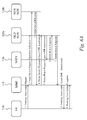
- FIG. 4A is a message diagram illustrating a network handover procedure resulting in the deactivation of ISR.
- FIG 4A illustrates a Tracking Area Update procedure that is very similar to the Routing Area Update procedure illustrated in FIG. 3A , except that a new MME is selected rather than a new SGSN.
- FIG. 4A includes UE 110, an old MME 118a, a new MME 118b, an SGSN 130, an SGW 120, and an HSS 124. ISR has been activated between the UE 110, the old MME 118a, the SGSN 130, and the SGW 120.
- Step 1 the UE 110 sends a Tracking Area Update Request message to the new MME 118b.
- the new MME 118b initiates a context exchange message flow by sending a Context Request message to the old MME 118a in Step 2.
- Step 3 the old MME 118a responds with the requested context information in a Context Response message. This message indicates that ISR was activated for the UE 110 at the old MME 118a.
- Step 5 the new MME 118b selects the SGW 120 that was used by the old MME 118a to serve the UE 110. Once selected, the new MME 118b initiates a bearer modification message flow with the SGW 120. The new MME 118b begins this flow by sending the SGW 120 a Modify Bearer Request message. This message indicates that ISR is to be deactivated.
- Step 6 the SGW 120 sends a Delete Bearer Request message to the SGSN 130. The SGSN 130 deletes its bearers because, upon ISR deactivation, it will no longer serve the UE 110 in parallel with the old MME 118a. The SGSN 130 responds with a Delete Bearer Response message in Step 7.
- the SGSN 130 If the SGSN 130 was maintaining any connections for the bearer being deleted, then the SGSN 130 sends a release command to the network and terminates the connection. When the last connection for the subscriber is deactivated, the SGSN 130 implicitly detaches the UE 110. In Step 8, the SGW 120 sends a Modify Bearer Response to the new MME 118b, which completes the bearer modification message flow.
- the new MME 118b begins a location update message flow by sending an Update Location message to the HSS 124.
- the Update Location message indicates the UE's new location to the HSS 124.
- This message also includes an Update Location Request flag set to indicate that this message is sent in response to an Initial Attach.
- the HSS 124 accordingly informs the old MME 118a and the SGSN 130 to cancel their respective location records for the UE 110, as ISR will be deactivated.
- the HSS 124 informs the old MME 118a of this change in a Cancel Location message.
- the old MME 118a confirms that it has removed the UE 110 from its records by sending a Cancel Location Answer message in Step 11.
- the Update Location message sent in Step 9 did not contain Update Location Request flags with an Initial Attach indicator set and so the HSS 124 does not transmit a Cancel Location message to the SGSN 130.
- the HSS 124 informs the SGSN 130 ofthis change in a Cancel Location message.
- the SGSN 130 confirms that it has removed the UE 110 from its records by sending a Cancel Location Answer message in Step 13.
- the HSS 124 sends an Update Location Answer message to the new MME 118b confirming that the location was successfully updated on the HSS 124, the old MME 118a, and the SGSN 130. This completes the location update message flow.
- Step 15 the new MME 118b sends a Tracking Area Update Accept message to the UE 110 indicating that UE's Tracking Area Update Request has been accepted. This message also indicates that ISR has been deactivated. The UE 110 confirms that the Tracking Area Update procedure is complete by sending a Tracking Area Update Complete message to the new MME 118b in Step 16.
- FIG. 4B is a message diagram illustrating a network handover procedure that continues ISR activation in accordance with some embodiments.
- FIG. 4B includes UE 110, an old MME 118a, a new MME 118b, an SGSN 130, an SGW 120, and an HSS 124.
- ISR has been activated between the UE 110, the old MME 118a, the SGSN 130, and the SGW 120.
- the UE 110 is registered with both the old MME 118a and the SGSN 130.
- both the old MME 118a and the SGSN 130 have control connections with the SGW 120.
- the old MME 118a, the new MME 118b, the SGSN 130, and the SGW 120 can support ISR continuation.
- Step 1 the UE 110 has moved into a Tracking Area served by the new MME 118b.
- the UE 110 detects this move and sends a Tracking Area Update Request message to the new MME 118b.
- Step 2 the new MME 118b requests context information from the old MME 118a by sending a Context Request message. This request is made so that the new MME 118b can serve the UE 110 without running a new attach procedure with the UE 110.
- the old MME 118a responds with a Context Response message in Step 3. Included in this message is the SGSN's F-TEID towards old MME and the SGSN's F-TEID towards SGW.
- This information is used by the new MME 118b to continue ISR activation in place of the old MME 118a.
- the SGSN's F-TEID towards old MME is used by the new MME 118b to communicate with the SGSN 130.
- the SGSN's F-TEID towards SGW is stored so that the new MME 118b can point a new SGW to the SGSN 130 if such a new SGW is later selected.
- a process of this nature is illustrated in FIG. 6B .
- Step 4 the new MME 118b sends a Context Acknowledge Message to the old MME 118a confirming the receipt of the message sent in Step 3.
- the new MME 118b Based on the Tracking Area Identities included in the Tracking Area Update Request message, the new MME 118b has selected the same SGW 120 that was previously serving the UE 110. In Step 5, the new MME 118b initiates a bearer modification message flow by sending a Modify Bearer Request message to the SGW 120. The new MME 118b sends the SGW 120 a Modify Bearer Request message. This message indicates that ISR mode is to be continued. On receipt of this message, the SGW 120 updates its tunnel information towards MME to use the new MME's F-TEID towards SGW. The SGW 120 no longer has connection information regarding the old MME 118a. At this point, the SGW 120 has parallel connections to both the SGSN 130 and the new MME 118b.
- Step 6 the SGW 120 sends a Modify Bearer Response message to the new MME 118b confirming that the tunnel information was updated correctly. This completes the bearer modification message flow begun in Step 5.
- Step 7 the new MME 118b initiates an ISR update message flow.
- the new MME 118b establishes itself as a new peer node with the SGSN 130, replacing the old MME 118a.
- the new MME 118b begins this flow by sending the SGSN 130 an ISR Update Request message.
- This message includes the new MME's F-TEID towards SGSN and the new MME's F-TEID towards SGW.
- Step 8 the SGSN 130 updates its control tunnel towards MME with the new MME's F-TEID towards MME and responds with an ISR Update Response message.
- Step 9 the new MME 118b initiates a location update message flow as in FIG. 4A by sending an Update Location message to the HSS 124.
- the HSS 124 informs the old MME 118a of this change in a Cancel Location message.
- the old MME 118a confirms that it has removed the UE 110 from its records in Step 11.
- the HSS 124 sends an Update Location Answer message to the new MME 118b confirming that the location was successfully updated on the HSS 124 and the old MME 118a.
- Step 13 the new MME 118b sends a Tracking Area Update Accept message to the UE 110 indicating that UE's Tracking Area Update Request has been accepted. This message also indicates that ISR remains activated.
- the UE 110 confirms that the Tracking Area update procedure is complete by sending a Tracking Area Update Complete message to the new MME 118b in Step 14. The Tracking Area Update procedure is complete.
- FIG. 5A is a message diagram illustrating a network handover procedure resulting in the deactivation of ISR.
- FIG. 5A includes UE 110, an SGSN 130, an MME 118, an old SGW 120a, and a new SGW 120b. This sequence occurs when an intra-SGSN Routing Area update causes the SGSN 130 to select a new SGW 120b. This may occur when the UE 110 moves to a new Routing Area served by the same SGSN 130 as the UE's previous Routing Area.
- Step 1 the UE 110 sends a Routing Area Update Request message to the SGSN 130.
- This message contains a new Routing Area Identity corresponding to the UE's new Routing Area.
- the SGSN 130 selects a new SGW 120b to serve the UE 110 based on the new Routing Area Identity and sends a Create Session Request message to the new SGW 120b in Step 2.
- the SGSN 130 establishes a control tunnel with the new SGW 120b.
- the Operation Indication bit of this message is set to indicate that that the message is sent due to an SGW switch.
- the new SGW 120b indicates to the PGW that the bearers for the UE 110 are to be routed through the new SGW 120b.
- the new SGW 120b sends a Create Session Response message to the SGSN 130 indicating that the bearers were correctly modified.
- Step 4 the SGSN 130 sends a Delete Session Request message to the old SGW 120a.
- the old SGW 120a responds by closing its existing control tunnel with the SGSN 130. This message indicates that ISR is to be deactivated.
- the old SGW 120a also informs the MME 118 to deactivate its bearers for the UE 110. The old SGW 120a does so by sending a Delete Bearer Request message to the MME 118 in Step 5.
- Step 6 the MME 118 locally deactivates its bearers for the UE 110.
- the UE 110 is implicitly detached from the MME 118.
- the MME 118 sends a Delete Bearer Response message confirming this deactivation to the old SGW 120a.
- Step 7 the old SGW 120a sends a Delete Session Response message to the SGSN 130 in response to the message sent in Step 4.
- Step 8 the SGSN 130 sends a Routing Area Update Accept message to the UE 110.
- This message indicates that ISR has been deactivated.
- the UE 110 deactivates ISR and sets its "Temporary Identity used in Next update" field equal to Packet Temporary Mobile Subscriber Identity.
- the UE 110 confirms receipt by sending a Routing Area Update Complete message to the SGSN 130 in Step 9.
- FIG. 5B is a message diagram illustrating a network handover procedure that continues ISR activation in accordance with some embodiments.
- FIG. 5B includes UE 110, an SGSN 130, an MME 118, an old SGW 120a, and a new SGW 120b.
- ISR is activated and the UE 110 is registered with both the SGSN 130 and the MME 118.
- the UE 110 moves into a new Routing Area that is served by the same SGSN as the UE's previous Routing Area.
- the SGSN 130 selects the new SGW 120b.
- the SGSN 130, the MME 118, the old SGW 120a and the new SGW 120b can support ISR continuation.
- the UE 110 sends a Routing Area Update Request message to the SGSN 130 in Step 1.
- This message contains the Routing Area Identity of the UE 110. Based on the mappings stored by the SGSN 130, this Routing Area Identity results in the selection of the new SGW 120b to serve the UE 110.
- the SGSN 130 also creates a control tunnel for the UE 110 towards the new SGW 120b.
- the SGSN 130 sends a Create Session Request message to the new SGW 120b in Step 2. This message contains an indication that this session being created due to SGW reselection. This message also indicates that ISR is to be continued.
- the SGSN 130 includes the MME's F-TEID towards SGW in the message. This F-TEID allows the new SGW 120b to open a control tunnel towards the MME 118.
- the new SGW 120b responds to the SGSN 130 with a Create Session Response message in Step 3. As the new SGW 120b supports ISR Continuation, this message indicates that ISR continuation is accepted. If the new SGW 120b did not support ISR continuation then it would proceed with the sequence illustrated in FIG. 5A , starting with Step 3, and ISR would not be continued.
- the SGSN 130 sends a Delete Session Request message to the old SGW 120a. This message indicates that the SGSN's session with the old SGW 120a is to be deleted but that ISR is to continue. Based on this indication, the old SGW 120a does not communicate with the MME 118 to deactivate the MME's bearers as illustrated in FIG. 5A . Rather, the old SGW 120a merely deactivates its bearers for the UE 110 locally. The old SGW 120a responds to the SGSN 130 with a Delete Session Response message in Step 6. This message indicates that ISR continuation has been accepted.
- the Delete Session Response message sent in Step 6 would not indicate that ISR continuation was accepted.
- the old SGW 120a would send a Delete Bearer Request message to the MME 118 as in Step 5 of FIG. 5A .
- the SGSN 130 would perform Steps 9 and 10 rather than Steps 7 and 8.
- Step 9 the SGSN 130 sends a Modify Bearer Request message to the new SGW 120b. This message indicates that the ISR continuation commenced in Step 2 is to be stopped.
- the new SGW 120b confirms that it has stopped ISR continuation in Step 10.
- Step 7 the SGSN 130 initiates an ISR update message flow with the MME 118.
- the SGSN 130 sends an ISR Update Request message to the MME 118, informing it of the change in SGW.
- This message contains the SGW's F-TEID.
- the MME 118 uses the F-TEID included in the message to update its SGW control tunnel to point to the new SGW 120b, rather than the old SGW 120a.
- the MME 118 has any active E-UTRAN Radio Access Bearers for the UE 110 it sends a release command to the E-UTRAN and locally releases any active connections.
- Step 8 the MME 118 sends an ISR Update Response message to the SGSN 130 indicating that the control tunnel was properly updated.
- Steps 9 and 10 are unnecessary in the case of the old SGW 120a supporting ISR continuation.
- Step 11 the SGSN 130 sends a Routing Area Update Accept message to the UE 110. If all of the access nodes supported ISR continuation (and so Steps 7 and 8 were run), the message indicates that ISR remains active. If any of the access nodes did not support ISR continuation the message indicates that ISR is deactivated. The UE 110 confirms receipt by sending a Routing Area Update Complete message to the SGSN 130 in Step 12.
- FIG. 6A is a message diagram illustrating a network handover procedure resulting in the deactivation of ISR.
- FIG. 6A includes UE 110, an MME 118, an SGSN 130, an old SGW 120a, and a new SGW 120b. This sequence occurs when an intra-MME Tracking Area update causes the new SGW 120b to be selected.
- ISR is activated between the UE 110, the MME 118, the SGSN 130 and the old SGW 120a.
- Step 1 the UE 110 sends a Tracking Area Update Request message to the MME 118.
- the MME 118 selects the new SGW 120b to serve the UE 110 based on the Tracking Area Identities contained in the Tracking Area Update Request message and sends a Create Session Request message to the new SGW 120b in Step 2.
- the MME 118 establishes a control tunnel with the new SGW 120b.
- the Operation Indication bit of the Create Session Request message is set to indicate that the message is sent due to an SGW switch. Accordingly, the new SGW 120b indicates to the PGW that the bearers for the UE 110 are now to be routed through the new SGW 120b.
- the new SGW 120b sends a Create Session Response message to the MME 118 indicating that the bearers were correctly modified.
- Step 4 the MME 118 sends a Delete Session Request message to the old SGW 120a.
- the old SGW 120a responds by closing its existing control tunnel with the MME 118. This message indicates that the reason the session being deleted is because ISR is being deactivated.
- the old SGW 120a also informs the SGSN 130 to deactivate its bearers for the UE 110. The old SGW 120a does so by sending a Delete Bearer Request message to the SGSN 130 in Step 5.
- Step 6 the SGSN 130 locally deactivates its bearers for the UE 110.
- the SGSN 130 also sends a Delete Bearer Response message confirming this deactivation to the old SGW 120a.
- Step 7 the old SGW 120a sends a Delete Session Response message to the MME 118.
- Step 8 the MME 118 sends a Tracking Area Update Accept message to the UE 110.
- This message indicates that ISR has been deactivated.
- the UE 110 deactivates ISR and sets its "Temporary Identity used in Next update" field equal to GUTI.
- the UE 110 confirms receipt by sending a Tracking Area Update Complete message to the MME 118 in Step 9.
- the Tracking Area Update procedure begun in Step 1 is complete and ISR is deactivated.
- FIG. 6B is a message diagram illustrating a network handover procedure that continues ISR activation in accordance with some embodiments.
- FIG. 6B includes UE 110, an MME 118, an SGSN 130, an old SGW 120a, and a new SGW 120b.
- this sequence occurs when an intra-MME Tracking Area update causes a new SGW to be selected.
- ISR is activated between the UE 110, the MME 118, the SGSN 130, and the old SGW 120a.
- the MME 118, the SGSN 130, the old SGW 120a and the new SGW 120b can support ISR continuation.
- the UE 110 is moved into a new Tracking Area that is served by the same MME 118.
- the UE 110 sends a Tracking Area Update Request message to the MME 118 in Step 1.
- This message contains the Tracking Area Identities of the UE 110. Based on the mapping stored by the MME 118, these Tracking Area Identities result in the selection of a new SGW 120b.
- the MME 118 creates a control tunnel for the UE 110 towards the new SGW 120b.
- the MME 118 sends a Create Session Request message to the new SGW 120b in Step 2.
- This message contains an indication that this session is being created due to SGW reselection. This message also indicates that ISR is to be continued.
- the MME 118 includes the SGSN's F-TEID towards SGW in the message. This F-TEID allows the new SGW to open a control tunnel towards the SGSN.
- the new SGW 120b responds to the MME 118 with a Create Session Response message in Step 3. As the new SGW 120b supports ISR Continuation, this message indicates that ISR continuation is accepted. If the new SGW 120b did not support ISR continuation then it would proceed with the sequence illustrated in FIG. 6A , starting with Step 3. In Step 4, the MME 118 sends a Delete Session Request message to the old SGW 120a. This message indicates that the session is to be deleted due to ISR continuation. Based on this indication, the old SGW 120a does not instruct the SGSN 130 to deactivate the SGSN's bearers, as is illustrated in FIG. 6A .
- the old SGW 120a merely deactivates its bearers for the UE 110 locally, as is illustrated in FIG. 5B .
- the old SGW 120a responds to the MME 118 with a Delete Session Response message in Step 6. This message indicates that ISR continuation has been accepted.
- the Delete Session Response message sent in Step 6 would not indicate that ISR continuation was accepted.
- the old SGW 120a would send a Delete Bearer Request message to the SGSN 130 as in Step 5 of FIG. 6A .
- the MME 118 would perform Steps 9 and 10 instead of Steps 7 and 8.
- Step 9 the MME 118 sends a Modify Bearer Request message to the new SGW 120b. This message indicates that the ISR continuation commenced in Step 2 is to be stopped.
- the new SGW 120b confirms that it has stopped ISR continuation in Step 10.
- Step 7 the MME 118 sends an ISR Update Request message to the SGSN 130, informing it of the change in SGW.
- This message contains the SGW's F-TEID.
- the SGSN 130 uses the F-TEID included in the message to update its SGW control connection to define a control tunnel towards the new SGW 120b rather than the old SGW 120a.
- Step 8 the SGSN 130 sends an ISR Update Response message to the MME 118 indicating that the control tunnel was properly updated. As described above, Steps 9 and 10 are unnecessary in the case that the old SGW 120a does support ISR continuation.
- Step 11 the MME 118 sends a Tracking Area Update Accept message to the UE 110. If all of the access nodes supported ISR continuation (and so Steps 7 and 8 were run rather than Steps 9 and 10), the message indicates that ISR remains active. If any of the access nodes did not support ISR continuation the message indicates that ISR is deactivated. The UE 110 confirms receipt by sending a Tracking Area Update Complete message to the MME 118 in Step 12.
- FIG. 7A is a message diagram illustrating a network handover procedure resulting in the deactivation of ISR.
- FIG. 7A includes UE 110, an old SGSN 130a, a new SGSN 130b, an MME 118, an old SGW 120a, a new SGW 120b, and an HSS 124.
- ISR is active on the UE 110, the old SGSN 130a, the MME 118, and the old SGW 120a. Both the old SGSN 130a and the MME 118 have control tunnels to the old SGW 120a.
- the UE 110 has been authenticated with the HSS 124, which is aware of the UE's location.
- the UE 110 has been moved to a new routing served by the new SGSN 130b.
- the UE 110 upon detecting this new Routing Area, sends a Routing Area Update Request message to the new SGSN 130b in Step 1.
- This message contains Routing Area Identities corresponding to both the UE's previous Routing Area and current Routing Area.
- the new SGSN 130b uses the Routing Area Identity corresponding to the UE's previous Routing Area received in Step 1.
- the new SGSN 130b sends the old SGSN 130a a Context Request message.
- the context being requested contains the UE's mobility management context as described earlier.
- the old SGSN 130a responds with the requested context by sending a Context Response message in Step 3. This message also indicates that ISR was active for the UE 110 at the old SGSN 130a.
- Step 4 the new SGSN 130b selects the new SGW 120b based on this Routing Area Identity corresponding to the UE's current Routing Area received in Step 1.
- Step 5 the new SGSN 130b sends a Context Acknowledgement message to the old SGSN 130a. This message indicates that a new SGW 120b has been selected.
- Step 6 the new SGSN 130b initiates the creation of a tunnel for the UE 110 with the new SGW 120b. The new SGSN 130b does so by sending the new SGW 120b a Create Session Request message.
- This message indicates that the reason for this new tunnel is that a new SGW has been selected and so the request is not to be forwarded to a PGW (as a session has already been established with a PGW). Instead, the new SGW 120b sends a Modify Bearer Request message to the PGW instructing the PGW to direct the UE's EPS bearer tunnel towards the new SGW 120b. The new SGW 120b responds with a Create Session Response message in Step 7.
- Step 8 the old SGSN 130a sends a Delete Session Request message to the old SGW 120a.
- This message indicates that ISR is to be deactivated.
- the old SGW 120a deletes its bearers locally and sends a Delete Bearer Request message to the MME 118 in Step 9.
- This message also indicates that ISR is to be deactivated.
- the MME 118 locally deactivates its bearers. If the MME 118 has any active E-UTRAN Radio Access Bearers for the bearer, it sends a release command through the E-UTRAN to release corresponding connections. If the MME 118 is receiving the request for the last connection for the UE 110, it performs an implicit detach from that UE 110.
- the MME 118 sends a Delete Bearer response to the old SGW 120a for each bearer that is deactivated.
- the old SGW 120a sends a Delete Session Response message to the old SGSN 130a confirming that the bearers were properly deactivated.
- the new SGSN 130b begins a location update message flow by sending an Update Location message to the HSS 124.
- This message includes an Update Location Request flag set to indicate that this message is sent in response to an Initial Attach.
- the HSS 124 accordingly informs the old SGSN 130a and the MME 118 to cancel their respective location records for the UE 110, as ISR will be deactivated.
- the HSS 124 informs the old SGSN 130a of this change in a Cancel Location message.
- the old SGSN 130a confirms that it has removed the UE 110 from its records in Step 14 by sending a Cancel Location Answer message.
- the HSS 124 informs the MME 118 of this change in a Cancel Location message.
- the MME 118 confirms that it has removed the UE 110 from its records in Step 16 by sending a Cancel Location Answer message.
- the HSS 124 sends an Update Location Answer message to the new SGSN 130b confirming that the location was successfully updated on the HSS 124, the old SGSN 130a and the MME 118.
- Step 18 the new SGSN 130b sends a Routing Area Update Accept message to the UE 110.
- This message indicates that ISR has been deactivated.
- the UE 110 sets its "Temporary Identity used in Next update" field equal to Packet Temporary Mobile Subscriber Identity.
- the UE 110 confirms receipt by sending a Routing Area Update Complete message to the new SGSN 130b in Step 19.
- FIG. 7B is a message diagram illustrating a network handover procedure that continues ISR activation in accordance with some embodiments.
- FIG. 7B includes UE 110, an old SGSN 130a, a new SGSN 130b, an MME 118, an old SGW 120a, a new SGW 120b, and an HSS 124.
- ISR is active on the UE 110, the old SGSN 130a, the MME 118 and the old SGW 120a.
- the old SGSN 130a, the MME 118, and the old SGW 120a nodes can support ISR continuation.
- Both the old SGSN 130a and the MME 118 have control tunnels to the old SGW 120a.
- the UE 110 has been authenticated with the HSS 124, which is aware of the UE's location.
- the UE 110 has been moved to a new routing served by the new SGSN 130b.
- the UE 110 upon detecting this new Routing Area, sends a Routing Area Update Request message to the new SGSN 130b in Step 1.
- This message contains Routing Area Identities corresponding to both the UE's previous Routing Area and current Routing Area.
- the new SGSN 130b uses the Routing Area Identity corresponding to the UE's previous Routing Area received in Step 1.
- the new SGSN 130b sends the old SGSN 130a a Context Request message.
- the context being requested contains the UE's mobility management context.
- the old SGSN 130a sends a Context Response message to the new SGSN 130b with the requested information.
- This response also indicates to the new SGSN 130b that ISR was active for the UE at the old SGSN 130a.
- the context response additionally includes the MME's F-TEID towards old SGSN and the MME's F-TEID towards old SGW.
- the new SGSN 130b does SGW selection based on the Routing Area Identity corresponding to the UE's new Routing Area received in Step 1.
- the new SGSN 130b selects the new SGW 120b to serve the UE.
- Step 5 the new SGSN 130b sends a Context Acknowledge message to the old SGSN 130a. This message indicates that despite the change in SGW, ISR mode will be continued.
- Step 6 the new SGSN 130b creates a new tunnel for the UE 110 to the new SGW 120b by sending a Create Session Request message. This message indicates that the reason for the new session is an SGW change and so the request is not to be forwarded to a PGW. Instead, the new SGW 120b sends a Modify Bearer Request message to the PGW instructing the PGW to direct UE's bearers tunnels towards the new SGW 120b.
- the Create Session Request message also includes an indication that ISR is to be continued.
- the message includes the MME's F-TEID towards old SGW.
- This F-TEID is used by the new SGW 120b to contact and direct signaling towards the MME 118 in parallel with the new SGSN 130b.
- the new SGW 120b sends a Create Session Response message to the new SGSN 130b.
- this message indicates that ISR continuation is supported. If the new SGW 120b did not support ISR continuation, this message would not contain this indication.
- the new SGSN 130b has a tunnel towards the new SGW 120b and the new SGW 120b has tunnels towards both the new SGSN 130b and the MME 118.
- Step 8 the old SGSN 130a sends a Delete Session Request message to the old SGW 120a. This message indicates that the session is to be deleted but ISR mode is continuing. The old SGSN 130a thus does not does instruct the MME 118 to delete its bearers for the UE 110.
- Step 9 the old SGW 120a locally deactivates its bearers. If the SGW 120a did not support ISR continuation then it informs the MME 118 to deactivate its bearers.
- Step 10 the old SGW 120a sends a Delete Session Response message to the old SGSN 130a. This message indicates that the old SGW 120a supports ISR continuation and so the continuation was accepted.
- Step 11 the new SGSN 130b sends an ISR Update Request message to the MME 118.
- This message is sent to the MME 118 using the MME's F-TEID towards old SGSN as learned in Step 3.
- This message includes the new SGSN's F-TEID towards MME, the new SGSN's F-TEID towards new SGW and the SGW's F-TEID.
- the MME 118 can establish a control tunnel with the new SGW 120b and continue ISR.
- the new SGSN's F-TEID towards MME and the new SGSN's F-TEID towards SGW are stored by the MME 118 so that the MME 118 can update a new MME and continue ISR if the MME 118 is later swapped out. If the Create Session Response message sent in Step 7 did not indicate that ISR continuation is supported, then the ISR Update Request message would indicate that ISR is to be discontinued. If the MME 118 received such an indication, it would deactivate its bearers for the UE 110. The MME 118 accepts ISR continuation unless it was instructed by the old SGW 120a to deactivate its bearers in Step 3. The MME 118 responds to the new SGSN 130b by sending an ISR Update Response message to the new SGSN 130b in Step 12. This message indicates whether the MME 118 accepted the ISR continuation.
- Step 13 the new SGSN 130b sends a Modify Bearer Request message to the new SGW 120b. This message indicates that ISR is deactivated.
- the new SGW 120b locally deactivates ISR.
- the new SGW 120b sends a Delete Bearer Request message to the MME 118.
- the MME 118 ignores this message because, in the case of ISR deactivation, its bearers for the UE 110 were deactivated in either Step 9 or Step 11.
- the new SGW 120b confirms that ISR was deactivated by sending a Modify Bearer Response message in Step 14.
- Step 15 a location update message flow is initiated by the new SGSN 130b.
- the new SGSN 130b sends an Update Location message to the HSS 124.
- This message requests that the HSS 124 store and distribute the new location of the UE 110 (the location corresponding to the Routing Area Identity received in Step 1).
- the HSS 124 sends a Cancel Location Message to the old SGSN 130a.
- the old SGSN 130a removes the UE 110 from its records.
- the old SGSN 130a confirms by sending a Cancel Location Answer in Step 17.
- the Update Location message sent in Step 15 did not contain Update Location Request flags with an Initial Attach indicator set and so the HSS 124 does not transmit a Cancel Location message to the MME 118.
- the HSS 124 confirms that the UE's location was updated by sending an Update Location Answer message in Step 18.
- the location update message flow is concluded.
- the new SGSN 130b responds to the UE 110 by sending a Routing Area Update Accept message in Step 19. If ISR Continuation was accepted by the old SGW 120a, the new SGW 120b, and the MME 118, this message indicates that ISR mode is active. Otherwise, this message indicates that ISR is deactivated. In Step 20, the UE 110 confirms receipt by sending a Routing Area Update Complete message.
- FIG. 8A is a message diagram illustrating a network handover procedure resulting in the deactivation of ISR.
- FIG. 8A includes UE 110, an old MME 118a, a new MME 118b, a SGSN 130, an old SGW 120a, a new SGW 120b, and an HSS 124.
- ISR is active on the UE 110, the old MME 118a, the SGSN 130, and the old SGW 120a.
- Both the old MME 118a and the SGSN 130 have control tunnels to the old SGW 120a.
- the UE 110 has been authenticated with the HSS 124, which is aware of the UE's location.
- the UE 110 has been moved to a tracking served by the new MME 118b.
- the UE 110 upon detecting this new Tracking Area, sends a Tracking Area Update Request message to the new MME 118b in Step 1.
- This message contains lists of Tracking Area Identities corresponding to both the UE's previous Tracking Areas and current Tracking Areas.
- the new MME 118b uses the Tracking Area Identities corresponding to the UE's previous Tracking Areas received in Step 1.
- the new MME 118b performs a DNS lookup to contact the old MME 118a in Step 2.
- the new MME 118b sends the old MME 118a a Context Request message.
- the context being requested contains the UE's mobility management context as described earlier.
- the old MME 118a responds with the requested context by sending a Context Response message in Step 3. This message also indicates that ISR was active for the UE 110 at the old MME 118a.
- Step 4 the new MME 118b selects the new SGW 120b based on the Tracking Area Identities corresponding to the UE's current Tracking Areas received in Step 1.
- Step 5 the new MME 118b sends a Context Acknowledgement message to the old MME 118a. This message indicates that a new SGW 120b has been selected.
- Step 6 the new MME 118b initiates the creation of a control tunnel for the UE 110 with the new SGW 120b. The new MME 118b does so by sending the new SGW 120b a Create Session Request message. This message indicates that the reason for this new tunnel is that the SGW has been re-selected and so the request is not to be forwarded to the PGW.
- the new SGW 120b sends a Modify Bearer Request message to the PGW instructing the PGW to direct the UE's bearers towards the new SGW 120b.
- the new SGW 120b responds with a Create Session Response message in Step 7.
- Step 8 the old MME 118a sends a Delete Session Request message to the old SGW 120a.
- This message indicates that ISR is to be deactivated.
- the old SGW 120a deletes its bearers locally and sends a Delete Bearer Request message to SGSN 130 in Step 9.
- This message also indicates that ISR is to be deactivated.
- the SGSN 130 locally deactivates its bearers. If the SGSN 130 has any active bearers, it releases them. If the SGSN 130 is receiving the request for the last connection for the UE 110, it performs an implicit detach from that UE 110.
- the SGSN 130 sends a Delete Bearer responds to the old SGW 120a for each bearer that is deactivated.
- the old SGW 120a sends a Delete Session Response message to the old SGSN 130a confirming that the bearers were properly deactivated.
- the new MME 118b begins a location update message flow by sending an Update Location message to the HSS 124.
- This message includes an Update Location Request flag set to indicate that this message is sent in response to an Initial Attach.
- the HSS 124 accordingly informs the old MME 118a and the SGSN 130 to cancel their respective location records for the UE 110, as ISR will be deactivated.
- the HSS 124 informs the old MME 118a of this change in a Cancel Location message.
- the old MME 118a confirms that it has removed the UE 110 from its records in Step 14 by sending a Cancel Location Answer message.
- the HSS 124 informs the SGSN 130 of this change in a Cancel Location message.
- the SGSN 130 confirms that it has removed the UE 110 from its records in Step 16 by sending a Cancel Location Answer message.
- the HSS 124 sends an Update Location Answer message to the new MME 118b confirming that the location was successfully updated on the HSS 124, the old MME 118a, and the SGSN 130.
- Step 18 the new MME 118b sends a Tracking Area Update Accept message to the UE 110 to complete the Tracking Area Update procedure that was initiated in Step 1. This message indicates that ISR has been deactivated.
- the UE sets its "Temporary Identity used in Next update" field equal to GUTI.
- the UE 110 confirms receipt by sending a Tracking Area Update Complete message to the new MME 118b in Step 19.
- FIG. 8B is a message diagram illustrating a network handover procedure that continues ISR activation in accordance with some embodiments.
- FIG. 8B includes UE 110, an old MME 118a, a new MME 118b, an SGSN 130, an old SGW 120a, a new SGW 120b, and an HSS 124.
- ISR is active on the UE 110, the old MME 118a, the SGSN 130, and the old SGW 120a.
- the old MME 118a, the SGSN 130, and the old SGW 120a can support ISR continuation.
- Both the old MME 118a and the SGSN 130 have control tunnels to the old SGW 120a.
- the UE 110 has been authenticated with the HSS 124, which is aware of the UE's location.
- the UE 110 has been moved to a new tracking served by the new MME 118b.
- the UE 110 upon detecting this new Tracking Area, sends a Tracking Area Update Request message to the new MME 118b in Step 1.
- This message contains Tracking Area Identities corresponding to both the UE's previous Tracking Area(s) and UE's current Tracking Area(s).
- the new MME 118b uses the Tracking Area Identities corresponding to the UE's previous Tracking Area received in Step 1.
- the new MME 118b sends the old MME 118a a Context Request message.
- the context being requested contains the UE's mobility management context.
- the old MME 118a sends a Context Response message to the new MME 118b with the requested information.
- This response also indicates to the new MME 118b that ISR was active for the UE 110 at the old MME 118a.
- the context response additionally includes the SGSN's F-TEID towards old MME and the SGSN's F-TEID towards old SGW.
- Step 4 the new MME 118b does SGW selection based on the Tracking Area Identities corresponding to the UE's new Tracking Area(s) received in Step 1.
- the new MME 118b selects the new SGW 120b to serve the UE 110.
- Step 5 the new MME 118b sends a Context Acknowledge message to the old MME 118a. This message indicates that despite the change in SGW, ISR mode will be continued.
- Step 6 the new MME 118b creates a control tunnel for the UE 110 to the new SGW 120b by sending a Create Session Request message. This message indicates that the reason for the new session is an SGW change and so the request is not to be forwarded to a PGW. Instead, the new SGW 120b sends a Modify Bearer Request message to the PGW instructing the PGW to direct UE's bearers towards the new SGW 120b.
- the Create Session Request message also includes an indication that ISR is to be continued.
- the message includes the SGSN's F-TEID towards old SGW.
- This F-TEID is used by the new SGW 120b. to contact and direct data towards the SGSN 130 in parallel with the new MME 118b.
- the new SGW 120b sends a Create Session Response message to the new MME 118b.
- this message indicates that ISR continuation is supported. If the new SGW 120b did not support ISR continuation, this message would not contain this indication.
- the new MME 118b has a tunnel towards the new SGW 120b and the new SGW 120b has tunnels towards both the new MME 118b and the SGSN 130 (not shown).
- Step 8 the old MME 118a sends a Delete Session Request message to the old SGW 120a.
- This message indicates that the session is to be deleted but ISR mode is continuing.
- the old SGW 120a thus does not does instruct the SGSN 130 to delete its bearers for the UE 110.
- Step 9 the old SGW 120a locally deactivates its bearers. If this SGW did not support ISR continuation then it would have informed the SGSN 130 to deactivate its bearers.
- Step 10 the old SGW 120a sends a Delete Session Response message to the old MME 118a. This message indicates that the old SGW 120a supports ISR continuation and so the continuation was accepted.
- Step 11 the new MME 118b sends an ISR Update Request message to the SGSN 130.
- This message is sent to the SGSN using the SGSN's F-TEID towards old MME as learned in Step 3.
- This message includes the new MME's F-TEID towards SGSN, the new MME's F-TEID towards new SGW and the SGW's F-TEID.
- the SGSN 130 can establish a control tunnel with the new SGW 120b and continue ISR.
- the new MME's F-TEID towards SGSN and the new MME's F-TEID towards SGW are stored by the SGSN 130 so that the SGSN 130 can update a new SGSN and continue ISR if the SGSN 130 is later swapped out. If the Create Session Response message sent in Step 7 did not indicate that ISR continuation is supported, then the ISR Update Request message would indicate that ISR is to be discontinued. If the SGSN 130 received such an indication, it would deactivate its bearers for the UE 110. The SGSN 130 accepts ISR continuation unless it was instructed by the old SGW 120a to deactivate its bearers in Step 3. The SGSN 130 responds to the new MME 118b by sending an ISR Update Response message to the new MME 118b in Step 12. This message indicates whether the SGSN 130 accepted the ISR continuation.
- Step 13 the new MME 118b sends a Modify Bearer Request message to the new SGW 120b. This message indicates that ISR is deactivated.
- the new SGW 120b locally deactivates ISR.
- the new SGW 120b sends a Delete Bearer Response message to the SGSN 130.
- the SGSN 130 ignores this message because, in the case of ISR deactivation, its bearers for the UE 110 were deactivated in either Step 9 or Step 11.
- the new SGW 120b confirms that ISR was deactivated by sending a Modify Bearer Response message in Step 14.
- Step 15 a location update message flow is initiated by the new MME 118b.
- the new MME 118b sends an Update Location message to the HSS 124.
- This message requests that the HSS 124 store the new location of the UE 110 and distribute this information.
- the HSS sends a Cancel Location Message to the old MME 118a.
- the old MME 118a removes the UE 110 from its records.
- the old MME 118a confirms by sending a Cancel Location Answer in Step 17.
- the Update Location message sent in Step 15 did not contain Update Location Request flags with an Initial Attach indicator set and so the HSS 124 does not transmit a Cancel Location message to the SGSN 130.
- the HSS 124 confirms that the UE's location was updated by sending an Update Location Answer message in Step 18.
- the new MME 118b responds to the UE 110 by sending a Tracking Area Update Accept message in Step 19.
- This message indicates that ISR mode is active. Otherwise, this message would have indicated that ISR is deactivated.
- the UE 110 confirms receipt by sending a Tracking Area Update Complete message.
- FIG. 9 illustrates a logical view of a wireless access node 200 in accordance with some embodiments.
- the wireless access node 200 can include one or more of a processor 202, a memory 204, a tunnel identifier storage 206 and an interface 208.
- An interface 208 can provide an input and/or output mechanism to communicate with other network devices.
- the interface 208 can provide communication with, for example, other gateways, wireless access nodes, application servers, and user equipment to send and receive data such as packets and messages.
- the interface 208 can be implemented in hardware to send and receive signals in a variety of mediums, such as optical, copper, and wireless, and in a number of different protocols some of which may be non-transient.
- a processor 202 runs software which uses the interface 208 and the memory 204 such as a tangible, non-transitory computer readable medium, a programmable read only memory (PROM), or flash memory.
- the processor 202 may be any computer chip that is capable of executing program instruction streams that are part of a software program.
- the processor 202 may have multiple cores for executing multiple streams of program instructions simultaneously.
- the processor 202 may also have multiple sub-processors which are optimized for executing particular categories of program instructions and are controlled by the processor 202.
- the memory 204 is capable of storing and retrieving program instructions, program data, or any other data that is used by the processor 204.
- the processor 202 may store and retrieve data from the memory 204 as a software program is executed.
- the memory 204 includes the tunnel identifier storage 206.
- the tunnel identifier storage 206 stores information used by the wireless access node 200 to maintain control connections with other nodes.
- the processor 202 accesses and updates the context data structures 206.
- the wireless access node 200 includes software which is configured to activate ISR for a mobile device.
- ISR may be activated when a mobile device switches between radio access technologies. This may occur when the mobile device is registered with a peer wireless access node using a first radio access technology and then moves to an area served by the wireless access node 200 using a second radio access technology. This change is indicated by a location update request message received by the interface 208.
- the wireless access node 200 may be a Serving GPRS Support Node (SGSN) whose interface 208 receives a Routing Area Update Request message.
- the peer wireless access node may be a Mobility Management Entity (MME).
- MME Mobility Management Entity
- the software is configured to exchange control tunnel identifiers with this peer wireless access node using the interface 208.
- the wireless access node 200 can provide the functionality of the SGSN 130 as illustrated in FIG. 2B .
- the software instructs the interface 208 to request context from the peer wireless access node so that the wireless access node 200 may obtain the information used to serve the mobile device. For example, this information may describe the subscription associated with the mobile device.
- the interface 208 is configured to receive two control tunnel identifiers from the peer wireless access node, both of which point to the peer wireless access node. For example, if the peer wireless access node is an MME, these control tunnel identifiers may be the MME's F-TEID towards SGW and the MME's F-TEID towards SGSN.
- the first of these control tunnel identifiers can be used by a gateway to establish a control tunnel with the peer wireless access node.
- the second of these control tunnel identifiers (e.g., an MME's F-TEID towards SGSN) can be used by a wireless access node to establish a control tunnel with the peer wireless access node.
- the wireless access node 200 stores these control tunnel identifiers in its tunnel identifier storage 206.
- the wireless access node 200 can use these control tunnel identifiers to communicate with the peer wireless access node or can share these identifiers with other nodes so that those nodes may communicate with the peer wireless access node.
- the interface 208 is further configured to transmit to the peer wireless access node two control tunnel identifiers, both of which point back to the wireless access node 206.
- these control tunnel identifiers may be the SGSN's F-TEID towards SGW and the SGSN's F-TEID towards MME.
- the first of these control tunnel identifiers (e.g., an SGSN's F-TEID towards SGW) can be used by a gateway to establish a control tunnel with the wireless access node 200.
- the second of these control tunnel identifiers can be used by another wireless access node (e.g., a peer MME) to establish a control tunnel with the wireless access node 200.
- these and other control tunnel identifiers may be Fully Qualified Tunnel Endpoint Identifiers (F-TEIDs) which point to the identified node by including an IP address of that node and a tunnel endpoint identifier.
- F-TEIDs Fully Qualified Tunnel Endpoint Identifiers
- the tunnel endpoint identifier is used to distinguish between Fully Qualified Tunnel Endpoint Identifiers having the same IP address but which are used for connection by different node types or for connections on behalf of different UEs.
- the wireless access node 200 also contains software configured to initiate a bearer modification messaging flow with a gateway using the interface 208. During this flow, the interface 208 transmits a request that the bearers for the mobile device from the gateway be routed through the wireless access node 208. This transmission may include an indication that ISR mode is activated.
- the wireless access node 200 additionally includes software which is configured to maintain ISR when a location update request message triggers the selection of a new gateway to serve the mobile device.
- the wireless access node can provide the functionality of the SGSN 130 as illustrated in FIG. 5B or the MME 118 as illustrated in FIG. 6B .
- This location update request message may be, for example, a Routing Area Update Request message or a Tracking Area Update Request message.
- the wireless access node 200 may select a new gateway to serve the sending mobile device.
- the wireless access node 200 is configured to create a control tunnel towards the gateway for the mobile device.
- the interface 208 transmits to the gateway an indication that ISR activation is to be continued.
- the interface 208 also transmits the peer wireless access node's control tunnel identifier that was learned during ISR activation. This control tunnel identifier allows the gateway to establish a control tunnel with the peer wireless access node.
- the wireless access node 200 is configured to initiate an ISR update message flow with the peer wireless access node. During this flow, the interface 208 transmits a control identifier of the gateway to the peer wireless access node.
- This identifier is transmitted so that the peer wireless access node can establish a control tunnel with the gateway and continue to serve the mobile device in parallel with the wireless access node.
- This transmission is directed towards the peer wireless access node using the control tunnel identifier received from the peer wireless access node during the ISR activation procedure as mentioned above.
- the interface 208 is configured to respond to the mobile device's location update request message with an indication that ISR remains activated.
- ISR can be also maintained when there is a wireless access node swap-out. This includes when there is a changeover of the MME or SGSN that is managing the mobile device.
- the wireless access node 200 can provide the functionality of the new SGSN 130b as illustrated in FIG. 3B or the new MME 118b as illustrated in FIG. 4B .
- the wireless access node 200 includes software which is configured to replace another wireless access node that has already activated ISR for a mobile device in conjunction with a peer wireless access node. This process may be triggered when the interface receives a location update request message from such a mobile device.
- the software is configured to communicate with the replaced wireless access node and obtain the information used to continue ISR and serve the mobile device in parallel with the peer wireless access node.
- the wireless access node 208 is configured to begin this process by requesting context for the mobile device from the replaced wireless access node.
- the wireless access node uses the interface 208 to receive the two control tunnel identifiers that were learned by the replaced wireless access node from the peer wireless access node during the ISR activation procedure.
- the first control tunnel identifier can be transmitted to a new gateway (if a new gateway is later selected, as described above) so that the new gateway can establish a control tunnel with the peer wireless access node.
- the second control tunnel identifier can be used by the wireless access node 200, or another wireless access node that may later replace the wireless access node 200, to establish a control tunnel with the peer wireless access node.
- These control tunnel identifiers are stored in the tunnel identifier storage 206.
- the wireless access node 200 is configured to initiate an ISR update message flow with the peer wireless access node.
- the interface 208 transmits two control tunnel identifiers of the wireless access node 200 to the peer wireless access node.
- the first of these control tunnel identifiers e.g., an MME's F-TEID towards SGW
- the second of these control tunnel identifiers can be used by another wireless access node (e.g., an SGSN) to establish a control tunnel with the wireless access node 200.
- These control tunnel identifiers replace the control tunnel identifiers that the peer wireless access node learned from the replaced wireless access node during ISR activation with that replace node.
- the wireless access node 200 may additionally select a new gateway to serve the mobile device.
- the wireless access node 200 can provide the functionality of the new SGSN 130b as illustrated in FIG. 7B or the new MME 118b as illustrated in FIG. 8B .
- the wireless access node 200 transmits to the new gateway an indication that ISR activation is to continue along with a control tunnel identifier of the peer wireless access node.
- the new gateway may use this control tunnel identifier to create a control tunnel with the peer wireless access node.
- the interface 208 transmits a request to the existing gateway that the bearers for the mobile device be routed through the wireless access node 200. This transmission includes an indication that ISR mode is to be activated.
- Parameter Included in Message Purpose of Parameter Scenario in which parameter may be used New SGSN's F-TEID towards MME ISR Update Request To inform a peer MME of the new SGSN's F-TEID towards the MME and continue ISR with the MME upon a SGSN-to-SGSN handover. SGSN-to-SGSN handover when ISR is active. New SGSN's F-TEID towards SGW ISR Update Request To inform a peer MME of the new SGSN's F-TEID towards the SGW.
- the MME can use this F-TEID on future SGW reselection to continue ISR with new SGW.
- SGSN-to-SGSN handover (with or without SGW reselection) when ISR is active.
- New MME's F-TEID towards SGSN ISR Update Request To inform a peer SGSN of the new MME's F-TEID towards the SGSN and continue ISR with the SGSN upon an MME-to-MME handover.
- MME-to-MME handover when ISR is active.
- New MME's F-TEID towards SGW ISR Update Request To inform a peer SGSN of the new MME's F-TEID towards the SGW.
- the SGSN can use this F-TEID on future SGW reselection to continue ISR with new SGW.
- MME-to-MME handover (with or without SGW reselection) when ISR is active.
- SGW's F-TEID ISR Update Request To inform an SGSN or MME of new SGW's F-TEID towards SGSN / MME, when a peer SGSN / MME selects a new SGW.
- SGSN-to-SGSN handover with SGW reselection or MME-to-MME handover with SGW reselection.
- Cause Accepted ISR Update Response
- Cause code indicating that ISR continuation was accepted by a peer wireless access node. All of the above situations.
- the user equipment described above can communicate with a plurality of radio access networks using a plurality of access technologies and with wired communication networks.
- the user equipment can be a smart phone offering advanced capabilities such as word processing, web browsing, gaming, e-book capabilities, an operating system, and a full keyboard.
- the user equipment may run an operating system such as Symbian OS, iPhone OS, RIM's Blackberry, Windows Mobile, Linux, Palm WebOS, and Android.
- the screen may be a touch screen that can be used to input data to the mobile device and the screen can be used instead of the full keyboard.
- the user equipment may have the capability to run applications or communicate with applications that are provided by servers in the communication network. The user equipment can receive updates and other information from these applications on the network.
- the user equipment also encompasses many other devices such as televisions (TVs), video projectors, set-top boxes or set-top units, digital video recorders (DVR), computers, netbooks, laptops, and any other audio/visual equipment that can communicate with a network.
- the user equipment can also keep global positioning coordinates, profile information, or other location information in its stack or memory.
- the user equipment can have a memory such as a computer readable medium, flash memory, a magnetic disk drive, an optical drive, a programmable read-only memory (PROM), and/or a read-only memory (ROM).
- the user equipment can be configured with one or more processors that process instructions and run software that may be stored in memory.
- the processor can also communicate with the memory and interfaces to communicate with other devices.
- the processor can be any applicable processor such as a system-on-a-chip that combines a CPU, an application processor, and flash memory.
- the interfaces can be implemented in hardware or software. The interfaces can be used to receive both data and control information from the network as well as local sources, such as a remote control to a television.
- the user equipment can also provide a variety of user interfaces such as a keyboard, a touch screen, a trackball, a touch pad, and/or a mouse.
- the user equipment may also include speakers and a display device in some embodiments.
- the wireless access node described above is implemented in a network device in some embodiments.
- This network device can implement multiple and different integrated functionalities.
- one or more of the following functionalities can be implemented on the network device including a security gateway (SeGW), an access gateway, a Gateway General packet radio service Serving Node (GGSN), a serving GPRS support node (SGSN), a packet data inter-working function (PDIF), an access service network gateway (ASNGW), a User Plane Entity (UPE), an IP Gateway, a session initiation protocol (SIP) server, a proxy-call session control function (P-CSCF), and an interrogating-call session control function (I-CSCF), a serving gateway (SGW), and a packet data network gateway (PDN GW), a mobility management entity (MME), a mobility access gateway (MAG), an HRPD serving gateway (HSGW), a local mobility anchor (LMA), a packet data serving node (PDSN), a foreign agent (FA), and/or home agent (HA).
- the functionalities are provided by a combination of hardware and software in the network device.
- General purpose hardware can be configured in the network device to provide one or more of these specialized functionalities.
- the network device is implemented using a collection of integrated circuit boards or cards. These cards include input/output interfaces for communication amongst each other, at least one processor for executing instructions and running modules that are stored in memory, and memory for storing data.
- FIG. 10 illustrates the implementation of a network device in accordance with some embodiments.
- the network device 300 includes slots 302 for loading application cards and line cards.
- a midplane can be used in the network device to provide intra-network device communications, power connections, and transport paths between the various installed cards.
- the midplane can include buses such as a switch fabric 304, a control bus 306, a system management bus, a redundancy bus 308, and a time division multiplex (TDM) bus.
- the switch fabric 304 is an IP-based transport path for user data throughout the network device implemented by establishing inter-card communications between application cards and line cards.
- the control bus 306 interconnects the control and management processors within the network device.
- the network device management bus provides management of system functions such as supplying power, monitoring temperatures, board status, data path errors, card resets, and other failover features.
- the redundancy bus 308 provides transportation of user data and redundancy links in the event of hardware failures.
- the TDM bus provides support for voice services on the system.
- the network device supports at least four types of application cards: a switch processor I/O card (SPIO) 310, a system management card (SMC) 312, a packet service card (PSC) 314, and a packet accelerator card (not shown).
- Other cards used in the network device include line cards 466 and redundant crossbar cards (RCC) 318.
- the line cards 316 when loaded in the network device, provide input/output connectivity to the network and other devices, as well as redundancy connections.
- the line cards 316 include interfaces to the network through Ethernet, Fiber Optic, and the other communication mediums.
- the redundant crossbar card (RCC) 318 includes a non-blocking crossbar and connections to each of the cards in the network device.
- the SPIO card 310 serves as a controller of the network device and is responsible for such things as initializing the network device and loading software configurations onto other cards in the network device.
- the system management card (SMC) 312 and switch processor card are system control and management cards for managing and controlling other cards in the network device.
- the packet accelerator card (PAC) and packet service card (PSC) 314 provide packet processing, context processing capabilities, and forwarding capabilities among other things.
- the PAC and PSC 314 perform packet-processing operations through the use of control processors and a network processing unit.
- the network processing unit determines packet processing requirements; receives and transmits user data frames to/from various physical interfaces; makes IP forwarding decisions; implements packet filtering, flow insertion, deletion, and modification; performs traffic management and traffic engineering; modifies/adds/strips packet headers; and manages line card ports and internal packet transportation.
- the control processors also located on the packet accelerator card, provide packet-based user service processing.
- the operating system software can be based on a Linux software kernel and run specific applications in the network device such as monitoring tasks and providing protocol stacks.
- the software allows network device resources to be allocated separately for control and data paths. For example, certain packet accelerator cards and packet services cards can be dedicated to performing routing or security control functions, while other packet accelerator cards/packet services cards are dedicated to processing user session traffic. As network requirements change, hardware resources can be dynamically deployed to meet the requirements in some embodiments.
- the system can be virtualized to support multiple logical instances of services, such as technology functions (e.g., a SeGW PGW, SGW, MME, HSGW, PDSN, ASNGW, PDIF, HA, or GGSN).
- technology functions e.g., a SeGW PGW, SGW, MME, HSGW, PDSN, ASNGW, PDIF, HA, or GGSN.
- the network device's software can be divided into a series of tasks that perform specific functions. These tasks communicate with each other as needed to share control and data information throughout the network device.
- a task is a software process that performs a specific function related to system control or session processing.
- Three types of tasks operate within the network device in some embodiments: critical tasks, controller tasks, and manager tasks.
- the critical tasks control functions that relate to the network device's ability to process calls such as network device initialization, error detection, and recovery tasks.
- the controller tasks mask the distributed nature of the software from the user and perform tasks such as monitor the state of subordinate manager(s), provide for intra-manager communication within the same subsystem, and enable inter-subsystem communication by communicating with controller(s) belonging to other subsystems.
- the manager tasks can control system resources and maintain logical mappings between system resources.
- a subsystem is a software element that either performs a specific task or is a culmination of multiple other tasks.
- a single subsystem can include critical tasks, controller tasks, and manager tasks.
- Some of the subsystems that can run on a network device include a system initiation task subsystem, a high availability task subsystem, a recovery control task subsystem, a shared configuration task subsystem, a resource management subsystem, a virtual private network subsystem, a network processing unit subsystem, a card/slot/port subsystem, and a session subsystem.
- the system initiation task subsystem is responsible for starting a set of initial tasks at system startup and providing individual tasks as needed.
- the high availability task subsystem works in conjunction with the recovery control task subsystem to maintain the operational state of the network device by monitoring the various software and hardware components of the network device.
- Recovery control task subsystem is responsible for executing a recovery action for failures that occur in the network device and receives recovery actions from the high availability task subsystem. Processing tasks are distributed into multiple instances running in parallel so if an unrecoverable software fault occurs, the entire processing capabilities for that task are not lost.
- User session processes can be sub-grouped into collections of sessions so that if a problem is encountered in one sub-group users in another sub-group will not be affected by that problem.
- the architecture also allows check-pointing of processes, which is a mechanism to protect the system against any critical software processes that may fail.
- the self-healing attributes of the software architecture protects the system by anticipating failures and instantly spawning mirror processes locally or across card boundaries to continue the operation with little or no disruption of service.
- This unique architecture allows the system to perform at the highest level of resiliency and protects the user's data sessions while ensuring complete accounting data integrity.
- Shared configuration task subsystem provides the network device with an ability to set, retrieve, and receive notification of network device configuration parameter changes and is responsible for storing configuration data for the applications running within the network device.
- a resource management subsystem is responsible for assigning resources (e.g., processor and memory capabilities) to tasks and for monitoring the task's use of the resources.
- Virtual private network (VPN) subsystem manages the administrative and operational aspects of VPN-related entities in the network device, which include creating separate VPN contexts, starting IP services within a VPN context, managing IP pools and subscriber IP addresses, and distributing the IP flow information within a VPN context.
- IP operations are done within specific VPN contexts.
- the network processing unit subsystem is responsible for many of the functions listed above for the network processing unit.
- the card/slot/port subsystem is responsible for coordinating the events that occur relating to card activity such as discovery and configuration of ports on newly inserted cards and determining how line cards map to application cards.
- the session subsystem is responsible for processing and monitoring a mobile subscriber's data flows in some embodiments.
- Session processing tasks for mobile data communications include: S1/S5/S8 interface termination for LTE networks, A10/A11 interface termination for CDMA networks, GSM tunneling protocol (GTP) termination for GPRS and/or UMTS networks, asynchronous PPP processing, IPsec, packet filtering, packet scheduling, Diffserv codepoint marking, statistics gathering, IP forwarding, and AAA services, for example.
- responsibility for each of these items can be distributed across subordinate tasks (called managers) to provide for more efficient processing and greater redundancy.
- a separate session controller task serves as an integrated control node to regulate and monitor the managers and to communicate with the other active subsystem.
- the session subsystem also manages specialized user data processing such as payload transformation, filtering, statistics collection, policing, and scheduling.
- the session subsystem can setup a MIPv4 termination and setup a PMIPv6 session towards the core network.
- a session manager can track the mapping of the sessions and processing to provide the emulation and inter-working between the networks.
- a database can also be used to map information between the sessions, and store, for example, NAI, HoA, AE information in some embodiments.
- FIG. 11 illustrates a logical view of the software architecture of a network device in accordance with certain embodiments. As shown, the software and hardware can be distributed within the network device and across different circuit boards, processors, and memory.
- the 11 includes a primary switch processor card (SPC)/system management card (SMC) 400a, a secondary SPC/SMC 400b, PAC/PSC 402a- 402d, a communication path 404, and a synchronization path 406.
- the SPC/SMC 400 include a memory 408, a processor 410, a boot configuration 412, high availability tasks 414, resource manager 416, switch fabric control 418, and controller tasks 420.
- the SPC/SMC 400 manage and control the network device including the other cards in the network device.
- the SPC/SMC 400 can be configured in a primary and secondary arrangement that provides redundancy and failsafe protection.
- the modules or tasks running on the SPC/SMC 400 are related to network device wide control and management.
- the boot configuration task 412 includes information for starting up and testing the network device.
- the network device can also be configured to startup in different configurations and providing different implementations. These can include which functionalities and services are capable of running on the SPC/SMC 400.
- the high availability task 414 maintains the operational state of the network device by monitoring the device and managing recovery efforts to avoid disruption of service.
- the resource manager tracks and assigns the available resources for sessions and demands on the network device.
- the switch fabric control 418 controls the communication paths in the network device.
- the controller tasks module 420 can manage the tasks among the resources of the networks to provide, for example, VPN services, assign ports, and create, delete, and modify sessions for user equipment.
- the PAC/PSC 402 are high-speed processing cards that are designed for packet processing and the tasks involved with providing various network functionalities on the network device.
- the PAC/PSC 402 include a memory 424, a network processing unit (NPU) 426, a processor 428, a hardware engine 430, an encryption component 432, a compression component 434, and a filter component 436.
- Hardware engines 430 can be deployed with the card to support parallel distributed processing for compression, classification traffic scheduling, forwarding, packet filtering, and statistics compilations.
- the components can provide specialize processing that can be done more efficiently than using a general processor in some embodiments.
- Each PAC/PSC 402 is capable of supporting multiple contexts.
- the PAC/PSC 402 are also capable of running a variety of tasks or modules.
- PAC/PSC 402a provides routing managers 422 with each covering routing of a different domain.
- PAC/PSC 402b provides a session manager 438 and an AAA manager 440.
- the session manager 438 manages one or more sessions that correspond to one or more user equipment.
- a session allows a user equipment to communicate with the network for voice calls and data.
- the AAA manager 440 manages accounting, authentication, and authorization with an AAA server in the network.
- PAC/PSC 402 provides a deep packet inspection task 442 and a signaling demux 444.
- the deep packet inspection task 442 provides inspection of packet information beyond layer 4 for use and analysis by the network device.
- the signaling demux 444 can provide scalability of services in combination with other modules.
- PAC/PSC 402d provides redundancy through standby tasks 446.
- Standby tasks 446 store state information and other task information so that the standby task can immediately replace an active task if a card fails or if there is a scheduled event to remove a card.
- the software needed for implementing a process or a database includes a high level procedural or an object-orientated language such as C, C++, C#, Java, or Perl.
- the software may also be implemented in assembly language if desired.
- Packet processing implemented in a network device can include any processing determined by the context. For example, packet processing may involve high-level data link control (HDLC) framing, header compression, and/or encryption.
- HDLC high-level data link control
- the software is stored on a storage medium or device such as read-only memory (ROM), programmable-read-only memory (PROM), electrically erasable programmable-read-only memory (EEPROM), flash memory, or a magnetic disk that is readable by a general or special purpose-processing unit to perform the processes described in this document.
- the processors can include any microprocessor (single or multiple core), system on chip (SoC), microcontroller, digital signal processor (DSP), graphics processing unit (GPU), or any other integrated circuit capable of processing instructions such as an x86 microprocessor.
- a method comprises activating a signaling reduction mode on a wireless access node for a mobile device in an idle state where the signaling reduction mode permits the mobile device to switch radio access technologies while maintaining registration with both the wireless access node and a peer wireless access node, exchanging with the peer wireless access node a first control tunnel identifier of the wireless access node and a second control tunnel identifier of the peer wireless access node, selecting at the wireless access node a second gateway to replace a first gateway, establishing a control connection with the second gateway, transmitting to the second gateway the second control tunnel identifier of the peer wireless access node so that the second gateway may establish a control connection with the peer wireless access node, and continuing the signaling reduction mode.
- LTE functionality such as a PDN gateway can be combined or co-located with the MME.
Abstract
Description
- The present disclosure relates generally to a system and method for providing a persistent signaling reduction mode within a telecommunications network.
- Wireless networks are telecommunications networks that use radio waves to carry information from one node in the network to one or more receiving nodes in the network. Cellular telephony is characterized by the use of radio cells that provide radio coverage for a geographic area, with multiple cells arranged to provide contiguous radio coverage over a larger area. Wired communication can also be used in portions of a wireless network, such as between cells or access points. Wireless communication technologies are used in connection with many applications, including, for example, satellite communications systems, portable digital assistants (PDAs), laptop computers, and mobile devices (e.g., cellular telephones, user equipment). Users of such applications can connect to a network (e.g., the Internet) as long as the user is within range of such a wireless communication technology.
- Each wireless communication technology has a corresponding radio access technology. In some geographical areas, network connectivity is achieved through a combination of radio access technologies. For example, as a new generation of radio access technologies are made available in an area, a mobile device is likely to receive a mix of service from a new generation radio access technology (e.g., E-UTRAN) and a previous generation radio access technologies (e.g., GERAN / UTRAN), switching between them often. The Idle state Signaling Reduction (ISR) mode, once activated, allows a mobile device to reselect between available radio access technologies with reduced radio signaling.
- Aspects and examples of the present invention are set out in the appended claims.
-
FIG. 1 illustrates a communications network in accordance with some embodiments; -
FIG. 2A is a message diagram illustrating idle mode signaling reduction activation; -
FIG. 2B is a message diagram illustrating idle mode signaling reduction activation in accordance with some embodiments; -
FIGS. 3A ,4A ,5A ,6A ,7A , and8A are message diagrams illustrating idle mode signaling reduction deactivation; -
FIGS. 3B ,4B ,5B ,6B ,7B , and8B are message diagrams illustrating idle mode signaling reduction continuation in accordance with some embodiments; -
FIG. 9 illustrates a logical view of a wireless access node in accordance with some embodiments; -
FIG. 10 illustrates a network device in accordance with some embodiments; and -
FIG. 11 illustrates a logical view of the software architecture of a network device in accordance with some embodiments. - Certain embodiments disclose a method comprising activating a signaling reduction mode on a wireless access node for a mobile device in an idle state where the signaling reduction mode permits the mobile device to switch radio access technologies while maintaining registration with both the wireless access node and a peer wireless access node, exchanging with the peer wireless access node a first control tunnel identifier of the wireless access node and a second control tunnel identifier of the peer wireless access node, selecting at the wireless access node a second gateway to replace a first gateway, establishing a control connection with the second gateway, transmitting to the second gateway the second control tunnel identifier of the peer wireless access node so that the second gateway may establish a control connection with the peer wireless access node, and continuing the signaling reduction mode.
- This disclosure relates generally to maintaining a signaling reduction mode for mobile devices in a communication network. Mobile devices such as smartphones, cell phones, and data-cards have continued to proliferate at a rapid pace. At the same time, the networks that serve these devices have continued to evolve. New generations of networks provide faster connections, increased reliability and improved user experiences. The deployment of these new networks often involves extensive rollout of new hardware that is achieved in phases of gradually increasing geographic scope. In areas where new networks are being rolled out, the network coverage available to mobile device users may be a mixture of old and new technologies. Users in these areas are likely to make use of several generations of technology and to transition between them frequently. Network handover procedures can make these transitions seamless to users.
- Network handover procedures allow a mobile device to maintain its network registration while roaming within the network. For example, a network handover procedure may occur when a user with a mobile device moves out of the range of one wireless transceiver and into the range of a new wireless transceiver that is part of the same network. The handover procedure may be initiated when the new transceiver receives a location update request message from the mobile device. This location update message indicates that the mobile device is requesting service from the new transceiver. In response, the nodes of the network exchange the information that is used to reconfigure the network and begin serving the mobile device from the new transceiver. A network handover procedure that accommodates a change from a transceiver using one radio access technology (RAT) to a transceiver using a different radio access technology is known as an inter-radio access technology handover. Idle mode signaling reduction (ISR) is a signaling reduction mode that, once activated, reduces resource-intensive radio signaling during an inter-radio access technology handover. This disclosure describes some embodiments that continue ISR activation on certain categories of network handovers.
- ISR works in areas that are served by both a GSM EDGE Radio Access Network (GERAN) or a UMTS Terrestrial Radio Access Network (UTRAN) and an evolved UMTS Terrestrial Radio Access Network (E-UTRAN). ISR, once activated, reduces the radio signaling that occurs during an inter-radio access technology handover between the GERAN / UTRAN radio access technology and the E-UTRAN radio access technology. A mobile device registers with a network through an initial attach procedure. ISR activation occurs, for example, when a mobile device already registered, or attached, using E-UTRAN roams into the range of a transceiver or base station using GERAN / UTRAN. In these cases, ISR is activated during the subsequent handover procedure run through GERAN / UTRAN. Once activated, ISR allows the mobile device to be simultaneously registered through both E-UTRAN and GERAN / UTRAN. A device that is simultaneously registered with both types of networks can reselect between them without re-registering. As such, a mobile device with ISR activated can roam freely between E-UTRAN and GERAN / UTRAN radio access technologies without the need to re-register. Network registration is a procedure that expends device battery life and network resources.
- Both the E-UTRAN and GERAN / UTRAN radio access technologies interact with a wireless access network to provide network services. In areas served by both E-UTRAN and GERAN / UTRAN, this wireless access network contains nodes used to interface, control, and carry traffic on behalf of both base stations using both radio access technologies. A mobile device registers with the access network and specifically with an access node to receive network services using a radio access technology. The access node includes network equipment in the access or core network that provide services to one or more mobile devices. The access node can be, for example, an MME, an SGSN, an SGW, a PGW, a PCRF, a GGSN, a PDSN, or any other applicable network device. The access node in some embodiments may include one or more of these functionalities. During ISR activation, the wireless access nodes exchange the information used to maintain parallel mobile device registration through both radio access technologies. A mobile device may move within a network once registered. As this occurs, new access nodes may be swapped with previously used access nodes to better serve the mobile device at its new location. These access nodes may also be swapped during a network handover procedure. In existing network implementations, the state stored during ISR activation is lost when access nodes are swapped. Thus, ISR is deactivated in these cases. This disclosure describes some embodiments where ISR activation is continued even when a network handover causes an access node to be swapped.
- ISR is an important mechanism to reduce the amount of wireless signaling sent to and from mobile devices that frequently reselect between E-UTRAN and GERAN / UTRAN radio access technologies. This reduction in signaling saves mobile device battery life and reduces load on the wireless spectrum. Thus, it is important to continue ISR activation even upon network handovers that cause an access node to be swapped. This disclosure describes some embodiments where the wireless access network nodes can distribute and store information during ISR activation to enable ISR continuation in the case of such a swap. This disclosure also describes embodiments where the wireless access network uses this stored information during such a swap to update the swapped-in access node with the information stored by the swapped-out access node. In these embodiments, the swapped-in node is able to continue ISR in place of the swapped-out node because of the stored information. Signaling reduction modes other than ISR, and mobile device selection between radio access technologies other than E-UTRAN and GERAN / UTRAN are other embodiments.
-
FIG. 1 illustrates a network diagram in accordance with certain embodiments.FIG. 1 illustrates a universal mobile telecommunication system (UMTS) network along with a LTE network. The network diagram ofFIG. 1 includes user equipment (UE) 110, an evolved nodeB (eNB) 112, a nodeB (NB) 114, a radio network controller (RNC) 116, a mobility management entity (MME) or user plane entity (UPE) 118, a system architecture evolution gateway (SAE GW) 120, a policy and charging rules function (PCRF) 122, home subscriber server (HSS) 124,core IP network 126,internet 128, Serving General packet radio service Support Node (SGSN) 130, and network management system (NMS) / element management system (EMS) 132. TheMME 118,SGSN 130, andSAE GW 120 can be implemented in a gateway as described below. TheSAE GW 120 can include a serving gateway (SGW) as well as a packet data network gateway (PGW). In some embodiments, the SGW and PGW can be implemented on separate network devices. The main component of the SAE architecture is the Evolved Packet Core (EPC), also known as SAE Core. The EPC includes the MME, SGW and PGW components. The user equipment (UE) can include a mobile phone, a laptop with wireless connectivity, a netbook, a smartphone, or any other wireless device. -
MME 118 is a control-node for the LTE access network. TheMME 118 is responsible forUE 110 tracking and paging procedures including retransmissions.MME 118 handles the bearer activation/deactivation process and is also responsible for choosing the SGW for aUE 110 at the initial attach and at time of an intra-LTE handover. TheMME 118 also authenticates the user by interacting with theHSS 124. TheMME 118 also generates and allocates temporary identities to UEs and terminates Non-Access Stratum (NAS) signaling. TheMME 118 checks the authorization of theUE 110 to camp on the service provider's Public Land Mobile Network (PLMN) and enforces UE roaming restrictions. TheMME 118 is the termination point in the network for ciphering/integrity protection for NAS signaling and handles the security key management. Lawful interception of signaling is also supported by theMME 118. The MME also provides the control plane function for mobility between LTE and 2G/3G access networks with the S3 interface terminating at theMME 118 from theSGSN 130. TheMME 118 also terminates the S6a interface towards the home HSS for roaming UEs. TheMME 118, theSGSN 130 and theSAE GW 120 are all part of the wireless access network. The wireless access network provides network access to radio access networks. The radio access networks include theeNB 112 and theRNC 116 /NB 114. - The SGW routes and forwards user data packets, while also acting as the mobility anchor for the user plane during inter-eNB handovers and as the anchor for mobility between LTE and other 3GPP technologies (terminating S4 interface and relaying the traffic between 2G/3G systems and PDN GW). For idle state UEs, the SGW terminates the down link data path and triggers paging when down link data arrives for the
UE 110. The SGW manages and stores UE contexts, e.g., parameters of the IP bearer service and network internal routing information. The SGW also performs replication of the user traffic in case of lawful interception. The P-GW provides connectivity to theUE 110 to external packet data networks by being the point of exit and entry of traffic for theUE 110. AUE 110 may have simultaneous connectivity with more than one PGW for accessing multiple packet data networks. The PGW performs policy enforcement, packet filtering for each user, charging support, lawful interception, and packet screening. The PGW also provides an anchor for mobility between 3GPP and non-3GPP technologies such as WiMAX and 3GPP2 (CDMA 1X and EvDO). - The NMS/
EMS 132 can provide management of the operation, administration, maintenance, and provisioning of networked system. Operation deals with keeping the network (and the services that the network provides) up and running smoothly, and includes monitoring to detect problems and minimize disruptions on the network. Administration deals with keeping track of resources in the network and how they are assigned. Maintenance is concerned with performing repairs and upgrades - for example, when equipment must be replaced, when a router needs a patch for an operating system image, when a new switch is added to a network. Provisioning is concerned with configuring resources in the network to support a given service. For example, this might include setting up the network so that a new customer can receive service. Functions that are performed as part of network management accordingly include controlling, planning, allocating, deploying, coordinating, and monitoring the resources of a network, network planning, frequency allocation, predetermined traffic routing to support load balancing, cryptographic key distribution authorization, configuration management, fault management, security management, performance management, bandwidth management, and accounting management. An element management system (EMS) consists of systems and applications that manage network elements (NE) on the network element management layer (NEL) of the Telecommunication Management Network model. - The user equipment (UE) may be in an active or an idle state. Whether the UE is in an active state can depend on the state of a packet data session, and whether there is an active packet data session. The idle state is a sleep mode state that can be used to conserve battery life of user equipment by minimizing the need to power receivers to be ready for radio signals. The paging indicators are usually sent from a number of cells because user equipment may move while in an idle state. For user equipment in an idle state, the SGW can buffer IP packets received for the user equipment and can initiate page requests towards the MME or SGSN. For user equipment with ISR activated, the SGW may initiate page requests towards both the MME and the SGSN. If the user equipment responds to the page, the SGW forwards the IP packet to the eNB in a LTE network or to a RNC/NB or SGSN in UMTS/general packet radio service (GPRS) for delivery to the user equipment.
- A UE first registers itself with an LTE network by initiating an Initial Attach procedure across E-UTRAN. During the initial attach procedure, the UE identifies itself to an E-UTRAN base station and requests to be served by the wireless access network. Within the wireless access network, the HSS interacts with the MME to authenticate the user and approve the attach request. Following authentication, a connection may be established between the UE and the SGW for the transmission of traffic to a packet data network (PDN). This process is known as Evolved Packet System (EPS) Bearer Activation. During EPS Bearer Activation, a connection tunnel is established between the UE and the PGW to carry a particular type of data, such as a voice conversation or streaming video. This connection passes through the SGW to the PGW. Specific forwarding and quality-of-service parameters are also configured as appropriate for the type of data that is to be sent. The portion of the tunnel from the SGW to the UE is called an E-UTRAN Radio Access Bearer (E-RAB). Once the UE has been authenticated and bearers have been established, the UE is attached to the network and has access to the packet data network.
- With E-UTRAN used in an LTE network, each UE may be located in one or more Tracking Areas. A Tracking Area defines a collection of eNBs that are geographically nearby. Each Tracking Area is defined by a Tracking Area Identity (TAI). To facilitate tracking of a UE, UEs periodically transmit Tracking Area Update (TAU) Request messages once attached to the network. A Tracking Area Update Request message is an example of a location update request message. Each Tracking Area Update Request message contains the Tracking Area Identity associated with the Tracking Area in which the UE is located. Upon receipt of a Tracking Area Update Request message, the wireless access network runs the Tracking Area Update procedure. During a Tracking Area Update procedure, the wireless access network may assign a new MME, a new SGW, or both, to serve the UE. The wireless access network will assign these wireless access nodes based on the Tracking Area Identity included in the request. The reassignment occurs as part of a network handover procedure. At the conclusion of a Tracking Area Update procedure, the wireless access network sends a Tracking Area Update Accept message to the UE. This message includes a list of Tracking Area Identities within which an idle state UE may move without signaling the core network.
- Similarly, with GERAN / UTRAN, a UE is located in a Routing Area. Like Tracking Areas, each Routing Area defines a collection of nodeBs that are geographically nearby. Each Routing Area is located within a location area. A Routing Area is defined by a Routing Area Identifier (RAI), which comprises a Routing Area Code, a Location Area Code, a Mobile Network Code (MNC), and a Mobile Country Code (MCC). As with Tracking Area Update Request messages, UEs periodically issue Routing Area Update (RAU) Request messages once attached to the network. A Routing Area Update Request message is another example of a location update request message. A Routing Area Update Request message contains the Routing Area Identities associated with both the UE's current and previous Routing Area. Upon receipt of a Routing Area Update Request message, the wireless access network runs the Routing Area Update procedure. The Routing Area Update procedure may cause the wireless access network to assign to new SGSN, a new SGW, or both, to serve the UE as part of a network handover procedure. The wireless access network assigns these nodes during such a handover procedure based on the Routing Area Identities included in the request. Both Routing Area Update Request messages and Tracking Area Update Request messages are types of location update request messages.
- The Routing Area Update and Tracking Area Update procedures are each comprised of a series of messages sent from one access node to another access node. Groups of sequential messages can be conceptually grouped into message flows which accomplish a discrete portion of a procedure. These message flows include a bearer modification message flow, a context exchange message flow, and a location update message flow. The bearer modification message flow modifies the route of the bearers established during initial attach. The context exchange message flow occurs when a UE initiates a Routing Area Update or Tracking Area Update procedure in an area served by a different MME or SGSN than had previously served the UE. This flow may transmit UE mobility management context information from the old MME to the new MME or from the old SGSN to the new SGSN. Mobility management context information includes any information that is used by the wireless access network to serve a particular UE, including the information used to maintain the bearers for the UE. This exchange gives the new MME or new SGSN the information used to serve the UE in place of the old MME or old SGSN. Alternatively, the context exchange message flow may transmit UE mobility management context information from an MME to an SGSN or from an SGSN to an MME. The location update message flow distributes up-to-date information on the location of a UE throughout the wireless access network. The location update message flow begins with new UE location information being sent to the HSS in an Update Location message. The HSS stores the location information. The Update Location message may also contain Update Location Request (ULR) flags which can either have an Initial Attach indicator either set or not set. If the Update Location Request flags have the Initial Attach indicator set, the flow proceeds with the HSS notifying both peer wireless access nodes in an ISR configuration to remove the UE's location from their records. If this indicator is not set, the flow proceeds with the HSS notifying a swapped-out wireless access node to remove the UE's location from its records. These notifications are sent as Cancel Location messages.
- If a UE is attached to a network through a GERAN / UTRAN radio access technology it may later move to an area served by E-UTRAN. If a UE detects such a move, it sends a Tracking Area Update request to register using the E-UTRAN interface. Similarly, a UE attached to a network using E-UTRAN may later move to any area served by GERAN / UTRAN and issue a Routing Area Update. In areas where LTE is not fully deployed and legacy GERAN / UTRAN radio access technology coverage is interworked with E-UTRAN radio access technology coverage, a UE is likely to frequently move between these radio access technologies. Without special functionality, an idle-mode UE that selects to change radio access technologies (from GERAN / UTRAN to E-UTRAN or from E-UTRAN to GERAN / UTRAN), issues either a Routing Area Update or Tracking Area Update request, respectively. Issuing a Routing Area Update or Tracking Area Update drains UE battery power and uses processing resources. As well, the receipt and processing of a Tracking Area Update request by an MME or a Routing Area Update request by a SGSN uses network resources.
- The idle mode signal reduction (ISR) function, described in 3GPP TS 23.401, Appendix J, enables signaling reduction by reducing the frequency of Routing Area Update and Tracking Area Update procedure initiations when a UE is registered with separate SGSN and MME nodes. With ISR, both the SGSN and MME nodes can have control connections with a single SGW. The ISR function is enabled by special functionality in the UE and the MME, SGSN and SGW nodes. The MME / SGSN will activate ISR for a UE only if the SGW can support ISR. ISR activation occurs when a UE that is attached to an MME using E-UTRAN later reselects GERAN / UTRAN and initiates a Routing Area Update procedures. Through ISR activation, the UE becomes registered with both an MME and an SGSN, both of these nodes storing associated mobility management information for their registration with the UE. The mobility management parameters stored by the SGSN include the associated Routing Area and Packet Temporary Mobile Subscriber Identity (P-TMSI) of the UE. The mobility management parameters stored by the MME are the associated Tracking Areas and Globally Unique Temporary ID (GUTI) of the UE. Once this information is stored and ISR is activated, an idle state UE can reselect between E-UTRAN and GERAN / UTRAN (within the registered Routing Area and Tracking Areas) without initiating a Tracking Area Update or Routing Area Update procedure. When ISR is activated and downlink data arrives, the SGW initiates paging processes through both the SGSN and MME, these nodes acting as peers to page the UE in parallel. In response to such paging, or for uplink data transfer, the UE can perform normal service request procedures using either radio access technology (e.g., either E-UTRAN or GERAN / UTRAN).
- ISR is activated with respect to a UE if the UE is registered with both an MME and a SGSN. The MME and SGSN act as peers to serve the UE in parallel. Thus, both the MME and the SGSN have a control connection with the SGW. A control connection may be a logical link or a session that is established at the connection endpoints to communicate data. The control connection may be communicated over wired mediums, wireless mediums, or a combination of the two. The MME and SGSN forward paging requests in parallel, as sent by the SGW using these connections. Control connections are used to manage and support user plane functions. Each control connection is modeled as a tunnel with two endpoints. A tunnel endpoint may be defined by a Fully Qualified Tunnel Endpoint Identifier (F-TEID). An F-TEID contains the Internet Protocol (IP) address of the endpoint plus a tunnel endpoint identifier. A tunnel endpoint identifier is allocated to define a tunnel that carries data for a particular UE (e.g., an identifier for a particular UE's connection between an MME and an SGW), and to distinguish between F-TEIDs which define tunnels to carry data other UEs. For example, a first node's F-TEID towards a second node includes the IP address of the first node and identifies a tunnel used to carry data related to a particular UE from the second node to the first node. The second node's F-TEID towards the first node includes the IP address of the second node and a tunnel endpoint identifier which identifies the tunnel as carrying traffic for that same UE, from the first node to the second node. Thus, when ISR is activated, the SGW stores the MME's F-TEID towards SGW and the SGSN's F-TEID towards SGW. These F-TEIDs are used by the SGW to communicate with the MME and the SGSN, respectively, on behalf of a particular UE. Both the MME and the SGSN store the SGW's F-TEID to communicate with the SGW on behalf of that UE. When data arrives at the core network for a UE with ISR activated, the SGW sends a notification to both the MME and the SGSN using these control tunnels. The MME and SGSN initiate their paging procedures in parallel.
- When ISR is activated for a UE, that UE stores mobility management parameters associated with both an MME and an SGSN. One of these parameters is the "Temporary Identity used in Next update (TIN)" field. A UE's "Temporary Identity used in Next update" field defines which temporary identity a UE will use in its next Routing Area Update or Tracking Area Update request. A "UE's Temporary Identity used in Next update" field may have one of the following values: Packet Temporary Mobile Subscriber Identity, Globally Unique Temporary Identity (GUTI) or radio access technology-related Temporary Mobile Subscriber Identity (RAT-related TMSI). A "Temporary Identity used in Next update" field equal to "Packet Temporary Mobile Subscriber Identity" indicates that the UE is attached via GERAN / UTRAN coverage and will send its Packet Temporary Mobile Subscriber Identity value in its next location update. A "Temporary Identity used in Next update" field equal to GUTI indicates that the UE is attached via E-UTRAN coverage and will send the GUTI that was assigned to the UE during the initial attach procedure in its next location update. A "Temporary Identity used in Next update" field equal to "RAT-related TMSI" indicates that ISR is activated for the UE. In this case, the UE simultaneously stores mobility management parameters from both an SGSN and an MME. For the connection to the SGSN, the UE stores a Packet Temporary Mobile Subscriber Identity and a Routing Area Identity. For the connection to the MME, the UE also stores a GUTI and one or more Tracking Area Identities. In this case, the UE's Packet Temporary Mobile Subscriber Identity and Routing Area Identity as well as its GUTI and Tracking Area Identity or Tracking Area Identities remain registered with the network. The UE is free to reselect between E-UTRAN and GERAN / UTRAN within its registered routing and Tracking Areas in this state without running a Routing Area Update or Tracking Area Update procedure.
- Existing ISR implementations deactivate ISR when the UE leaves the Routing Area or Tracking Areas in which ISR was initially activated. A UE's departure from a Routing Area or Tracking Area may result in the selection of a new MME, a new SGSN or a new SGW during a Routing Area Update procedure or a Tracking Area Update procedure. Existing ISR implementations do not contain functionality to continue ISR upon this type of access node change. As ISR is presently specified, the state information stored in the UE, MME and SGSN would become unsynchronized on occurrence of access node change and ISR would be deactivated. Some embodiments of this disclosure allow ISR continuation upon SGSN change, MME change or SGW changes. Other embodiments allow for ISR continuation upon SGSN and SGW change or MME change and SGW changes.
- To support ISR continuation, an improved ISR activation method includes the exchange and storage of information used to update new wireless access nodes that are swapped in during Tracking Area Update or Routing Area Update procedures. In some embodiments, the MME sends its F-TEID towards SGW to the SGSN. An MME's F-TEID towards SGW includes the Internet Protocol (IP) address of the MME and a tunnel endpoint identifier (an identifier used to identify a particular UE's connection towards an SGW). As well, the SGSN sends its F-TEID towards SGW to the MME. An SGSN's F-TEID towards SGW includes the IP address of the SGSN and a tunnel endpoint identifier (an identifier used to identify a particular UE's connection towards an SGW). This information, once exchanged, enables an access node to initiate an ISR update message flow with another access node during a subsequent Routing Area Update or Tracking Area Update procedure. The ISR update message flow brings a new access node up-to-date with the information used to continue ISR and prevents ISR state information from becoming unsynchronized.
- If a new MME is swapped in for an old MME upon during a Tracking Area Update procedure, the old MME informs the new MME of the SGSN's tunnel information towards MME and SGW. Using this tunnel information, the new MME initiates an ISR update message flow to inform the SGSN of its new tunnel information towards the SGW and the SGSN. This connection from the new MME to the SGW allows the new MME to serve the UE in parallel with the SGSN. ISR can thus be continued because, as when ISR was activated, there remains an MME and an SGSN with connections to the SGW. Similarly, if a new SGSN is swapped in for an old SGSN during a Routing Area Update procedure, the old SGSN brings the new SGSN up-to-date with tunnel information used by the MME towards the SGSN and the SGW. In turn, the new SGSN informs the MME about its tunnel information towards the SGW by initiating an ISR update message flow. ISR continuation can also be achieved when an MME or SGSN selects a new SGW by informing the peer SGSN or peer MME, respectively, of the new SGW's F-TEID. An SGW's F-TEID includes the IP address of the SGW and a tunnel endpoint identifier used to identify a UE's connection by an MME or SGSN towards the SGW.
-
FIG. 2A is a message diagram illustrating a method of ISR activation.FIG. 2A includesUE 110, anMME 118, anSGSN 130, and anHSS 124. The attach procedure begins with theUE 110 sending an Attach Request message to theMME 118 inStep 1. This message contains the UE's GUTI, which is either an actual GUTI or one mapped from the UE's Packet Temporary Mobile Subscriber Identity, depending on the UE's "Temporary Identity used in Next update" field as described above. InStep 2, theMME 118 and theHSS 124 interact to authenticate theUE 110 based on the GUTI sent inStep 1. If theMME 118 authenticates theUE 110, it sends an Attach Accept message to theUE 110 inStep 3. This message contains the UE's new GUTI as allocated by the access network. AfterStep 3, theUE 110 is able to interact with the network via E-UTRAN. - Following Steps 1 - 3, the
UE 110 may move to an area with GERAN / UTRAN coverage. Upon detecting this radio access technology change, theUE 110 sends a Routing Area Update message inStep 4. This message contains the UE's Packet Temporary Mobile Subscriber Identity mapped from the GUTI received inStep 3. This message is received by a GERAN / UTRAN base station and passed on to theSGSN 130. As theUE 110 is already attached via E-UTRAN, this represents an opportunity to activate ISR. To do so, theSGSN 130 initiates a context exchange message flow with theMME 118. TheSGSN 130 initiates this flow by sending a Context Request message to theMME 118 inStep 5. InStep 6, theMME 118 responds by sending a Context Response message including the requested context information and indicating that it is capable of operating in ISR mode. TheSGSN 130 confirms receipt of the context information and that ISR mode is activated by sending a Context Acknowledge message inStep 7. AfterStep 7, both theMME 118 and theSGSN 130 have stored the UE context information and have parallel control connections with an SGW (not shown). InStep 8, theSGSN 130 andHSS 124 interact to authenticate theUE 110 based on the Packet Temporary Mobile Subscriber Identity sent inStep 4. InStep 9, theSGSN 130 responds to theUE 110 with a Routing Area Update Accept message containing the UE's new Packet Temporary Mobile Subscriber Identity. This message also indicates to theUE 110 that ISR is activated. The Routing Area Update procedure is complete and ISR is activated. -
FIG. 2B is a message diagram illustrating a method of activating ISR to enable ISR continuation in accordance with some embodiments.FIG. 2B includesUE 110, anMME 118, anSGSN 130, anSGW 120, and anHSS 124. TheUE 110, theMME 118, theSGSN 130, and theSGW 120 can support ISR. Furthermore, theMME 118, theSGSN 130, and theSGW 120 can support ISR continuation. An Initial Attach procedure begins with theUE 110 sending an Attach Request message inStep 1. This Initial Attach procedure does not require any special functionality for support of ISR or ISR continuation. As inFIG. 2A , the Attach Request message contains the UE's GUTI, which is either an actual GUTI or one mapped from the UE's Packet Temporary Mobile Subscriber Identity, depending on the UE's "Temporary Identity used in Next update" field. InStep 2, theMME 118 and theHSS 124 interact to authenticate theUE 110 based on the GUTI sent inStep 1. If theUE 110 is properly authenticated, theMME 118 sends an Attach Accept message to theUE 110 inStep 3. This message contains the UE's new GUTI as allocated by the access network. This message does not indicate that ISR is activated and so any ISR state information stored by theUE 110 is cleared. AfterStep 3, theUE 110 is able to interact with the network via E-UTRAN and ISR is deactivated. InStep 4, bearers are established for theUE 110. - An opportunity to activate ISR arises when the
UE 110 has been moved from an area served by an E-UTRAN base station and into an area served by a GERAN / UTRAN base station. When theUE 110 detects such a move, it sends a Routing Area Update Request message inStep 5. This message is received by the GERAN / UTRAN radio access network and forwarded to theSGSN 130. This message contains the UE's Packet Temporary Mobile Subscriber Identity mapped from the GUTI received inStep 3. This message also contains the UE's current and previous Routing Area Identities. Rather than obtaining the context used to serve theUE 110 from theUE 110 itself, theSGSN 130 obtains this information from theMME 118 by initiating a context exchange flow. This flow begins when theSGSN 130 requests theUE 110 context information from theMME 118 inStep 6. InStep 7, theMME 118 responds by sending a Context Response Message containing the requested context information and indicating that is it capable of operating in ISR mode. - For ISR to be continued in the event of an MME, SGSN or SGW change, information is exchanged during ISR activation beyond what is used to merely activate ISR. To support ISR continuation, the
SGSN 130 learns MME's F-TEID towards SGW. Similarly, theMME 118 learns the SGSN's F-TEID towards SGW. In this way, if a new SGW is swapped in, either of the peers is able to send the new SGW the other peer's F-TEID towards SGW so that the new SGW can contact that other peer. Similarly, when peer MME and SGSN nodes are aware of each other's F-TEID towards SGW, they are able to update a newly swapped-in peer node. InStep 7, theMME 118 begins this exchange by sending a Context Response message to theSGSN 130 which contains the MME's F-TEID towards SGW. This message also indicates to theSGSN 130 that theMME 118 supports ISR. - In
Step 8, theSGSN 130 initiates a bearer modification message flow with theSGW 120. TheSGSN 130 begins this process by sending a Modify Bearer Request message to theSGW 120. This Modify Bearer Request message indicates that ISR has been established between theSGSN 130 and theMME 118. TheSGW 120 responds by sending a Modify Bearer Response message inStep 9. This message indicates that theSGW 120 supports ISR. The bearers are modified bySteps UE 110 through theSGSN 130 to theSGW 120. - In
Step 10, theSGSN 130 sends a Context Acknowledge message to theMME 118. This message contains the SGSN's F-TEID towards SGW, completing the exchange of F-TEIDs begun inStep 7. This message also indicates that ISR has been activated. InStep 11, theSGSN 130 andHSS 124 interact to update theHSS 124 on the location of theUE 110. InStep 12, theSGSN 130 responds to theUE 110 with a Routing Area Update Accept message containing the UE's new Packet Temporary Mobile Subscriber Identity. This message also indicates to theUE 110 that ISR is activated. The Routing Area Update procedure begun inStep 5 is complete. -
FIG. 3A is a message diagram illustrating a network handover procedure resulting in the deactivation of ISR.FIG. 3A includesUE 110, anold SGSN 130a, anew SGSN 130b, anMME 118, anSGW 120, and anHSS 124. ISR has been activated between theUE 110,old SGSN 130a, theMME 118, and theSGW 120. This procedure occurs when theUE 110 has moved from an area served by a first GERAN / UTRAN base station into an area served by a second GERAN / UTRAN base station. Anold SGSN 130a serves the first base station and anew SGSN 130b serves the second base station. InStep 1, theUE 110 sends a Routing Area Update Request message to thenew SGSN 130b. A context exchange flow begins when thenew SGSN 130b requests context information from theold SGSN 130a inStep 2. InStep 3, theold SGSN 130a responds with the requested context information in a Context Response message. This message indicates that ISR was activated for theUE 110 at theold SGSN 130a. - In
Step 5, thenew SGSN 130b selects theSGW 120 that was used by theold SGSN 130a to serve theUE 110. If thenew SGSN 130b selected a different SGW then the procedure illustrated inFIG. 7A would occur instead of the procedure illustrated inFIG. 3A . Once theSGW 120 is selected, thenew SGSN 130b begins a bearer modification message flow with theSGW 120. Thenew SGSN 130b begins this flow by sending theSGW 120 a Modify Bearer Request message. This message indicates that ISR is to be deactivated. InStep 6, theSGW 120 sends a Delete Bearer Request message to theMME 118. TheMME 118 deletes its bearers because, upon ISR deactivation, it will no longer serve theUE 110 in parallel with theold SGSN 130a. If theMME 118 had any E-UTRAN Radio Access Bearers activated for the bearer being deleted, it sends a release command to the E-UTRAN and releases the E-UTRAN connection. When the last connection for theUE 110 is deactivated, theMME 118 implicitly detaches from theUE 110. TheMME 118 responds with a Delete Bearer Response message inStep 7. InStep 8, theSGW 120 completes the bearer modification message flow by sending a Modify Bearer Response to thenew SGSN 130b. - In
Step 9, thenew SGSN 130b begins a location update message flow by sending an Update Location message to theHSS 124. TheHSS 124 is responsible for tracking the location of theUE 110 within the network and so is informed of the UE's new location. TheHSS 124, once so informed, can update other nodes in the network with the UE's new location. The Update Location message indicates the UE's new location to theHSS 124. This message also includes an Update Location Request flag set to indicate that this message is sent in response to an Initial Attach. TheHSS 124 accordingly informs theold SGSN 130a and theMME 118 to cancel their respective location records for theUE 110, as ISR will be deactivated. InStep 10, theHSS 124 informs theold SGSN 130a of this change in a Cancel Location message. Theold SGSN 130a confirms that it has removed theUE 110 from its records inStep 11. InStep 12, theHSS 124 informs theMME 118 of this change in a Cancel Location message. TheMME 118 confirms that it has removed theUE 110 from its records inStep 13. InStep 14, theHS S 124 completes the location update message flow by sending an Update Location Answer message to thenew SGSN 130b confirming that the location was successfully updated on theHSS 124, theold SGSN 130a, and theMME 118. - In
Step 15, thenew SGSN 130b sends a Routing Area Update Accept message to theUE 110 indicating that UE's Routing Area Update Request has been accepted. This message also indicates that ISR has been deactivated. TheUE 110 confirms that the Routing Area Update procedure is complete by sending a Routing Area Update Complete message to thenew SGSN 130b inStep 16. -
FIG. 3B is a message diagram illustrating a network handover procedure that continues ISR activation in accordance with some embodiments.FIG. 3B includesUE 110, anold SGSN 130a, anew SGSN 130b, anMME 118, anSGW 120, and anHSS 124. As withFIG. 3A , ISR has been activated between theUE 110, theold SGSN 130a, theMME 118, and theSGW 120. TheUE 110 is registered with both theold SGSN 130a and theMME 118. Both theold SGSN 130a andMME 118 have control connections with theSGW 120. Theold SGSN 130a, thenew SGSN 130b, theMME 118, and theSGW 120 can support ISR continuation. ISR was activated on these nodes in accordance with the method illustrated inFIG. 2B . - In
Step 1, theUE 110 has moved into a Routing Area served by thenew SGSN 130b. TheUE 110 detects this move and sends a Routing Area Update Request message to thenew SGSN 130b. This message includes the Routing Area Identities corresponding to both the UE's current and previous Routing Area. InStep 2, thenew SGSN 130b initiates a context exchange flow. This flow beings with thenew SGSN 130b requesting context information from theold SGSN 130a by sending a Context Request message. Theold SGSN 130a responds with a Context Response message inStep 3. Included in this message is the MME's F-TEID towards old SGSN and the MME's F-TEID towards SGW. An MME's F-TEID towards an SGSN includes the IP address of the MME and a tunnel endpoint identifier which identifies the tunnel as carrying data from an SGSN on behalf of a particular UE (e.g., that UE's context towards the SGSN). Similarly, as mentioned above, an MME's F-TEID towards SGW includes the IP address of the MME and a tunnel endpoint identifier that represents a connection on behalf of a particular UE from an SGW. This information is used by thenew SGSN 130b to continue ISR activation. In particular, the MME's F-TEID towards old SGSN is used by thenew SGSN 130b to communicate with theMME 118. The MME's F-TEID towards SGW is stored so that thenew SGSN 130b can point a new SGW to theMME 118 if such a new SGW is later selected. A procedure where ISR is continued following such a selection of a new SGW is illustrated inFIG. 5B . InStep 4, thenew SGSN 130b send a Context Acknowledge Message to theold SGSN 130a confirming the receipt of the message sent inStep 3. - Based on the Routing Area Identities included in the Routing Area Update Request message, the
new SGSN 130b has selected thesame SGW 120 that was previously serving theUE 110. InStep 5, thenew SGSN 130b begins a bearer modification message flow with theSGW 120 by sending a Modify Bearer Request message. Thenew SGSN 130b sends theSGW 120 a Modify Bearer Request message. This message indicates that ISR mode is to be continued. On receipt of this message, theSGW 120 updates its tunnel information towards SGSN to use the new SGSN's F-TEID towards SGW. TheSGW 120 no longer has connection information regarding theold SGSN 130a. At this point, theSGW 120 has parallel connections to both theMME 118 and thenew SGSN 130b. ISR mode can continue with thenew SGSN 130b responsible for GERAN / UTRAN communication with theUE 110 in place of theold SGSN 130a. InStep 6, theSGW 120 concludes the bearer modification message flow by sending a Modify Bearer Response message to thenew SGSN 130b confirming that the tunnel information was updated correctly. - In
Step 7, thenew SGSN 130b begins an ISR update message flow. Through this flow, thenew SGSN 130b establishes itself as a new ISR peer node with theMME 118, replacing theold SGSN 130a. Thenew SGSN 130b begins this process by sending theMME 118 an ISR Update Request message. This message includes the new SGSN's F-TEID towards MME and the new SGSN's F-TEID towards SGW. An SGSN's F-TEID towards an MME includes the IP address of the SGSN and a tunnel endpoint identifier which identifies the tunnel as carrying data from an MME on behalf of a particular UE (e.g., that UE's context towards the MME). Similarly, as mentioned above, an SGSN's F-TEID towards SGW includes the IP address of the SGSN and a tunnel endpoint identifier that represents a connection on behalf of a particular UE from an SGW. InStep 8, theMME 118 updates its control tunnel towards SGSN with the new SGSN's F-TEID towards MME. TheMME 118 responds with an ISR Update Response message to conclude the ISR update message flow. - In
Step 9, thenew SGSN 130b begins a location update message flow, as inFIG. 3A , by sending an Update Location message to theHSS 124. InStep 10, theHSS 124 informs theold SGSN 130a of the UE's new location by sending a Cancel Location message to theold SGSN 130a. Theold SGSN 130a confirms that it has removed theUE 110 from its records inStep 11. The Update Location message sent inStep 9 did not contain Update Location Request flags with an Initial Attach indicator set and so theHSS 124 does not transmit a Cancel Location message to theMME 118. InStep 12, theHSS 124 sends an Update Location Answer message to thenew SGSN 130b confirming that the location was successfully updated on theHSS 124 and theold SGSN 130a. - In
Step 13, thenew SGSN 130b sends a Routing Area Update Accept message to theUE 110 indicating that UE's Routing Area Update Request has been accepted. This message also indicates that ISR remains activated. TheUE 110 confirms that the Routing Area Update procedure is complete by sending a Routing Area Update Complete message to thenew SGSN 130b inStep 14. -
FIG. 4A is a message diagram illustrating a network handover procedure resulting in the deactivation of ISR. In particular,FIG 4A illustrates a Tracking Area Update procedure that is very similar to the Routing Area Update procedure illustrated inFIG. 3A , except that a new MME is selected rather than a new SGSN.FIG. 4A includesUE 110, anold MME 118a, anew MME 118b, anSGSN 130, anSGW 120, and anHSS 124. ISR has been activated between theUE 110, theold MME 118a, theSGSN 130, and theSGW 120. This procedure can occur, for example, when theUE 110 has moved from a first Tracking Area to a second Tracking Area outside the list of tracking areas that was sent to the UE by theold MME 118a. In that case, theold MME 118a serves the first Tracking Area and thenew MME 118b serves the second Tracking Area. InStep 1, theUE 110 sends a Tracking Area Update Request message to thenew MME 118b. Thenew MME 118b initiates a context exchange message flow by sending a Context Request message to theold MME 118a inStep 2. InStep 3, theold MME 118a responds with the requested context information in a Context Response message. This message indicates that ISR was activated for theUE 110 at theold MME 118a. - In
Step 5, thenew MME 118b selects theSGW 120 that was used by theold MME 118a to serve theUE 110. Once selected, thenew MME 118b initiates a bearer modification message flow with theSGW 120. Thenew MME 118b begins this flow by sending theSGW 120 a Modify Bearer Request message. This message indicates that ISR is to be deactivated. InStep 6, theSGW 120 sends a Delete Bearer Request message to theSGSN 130. TheSGSN 130 deletes its bearers because, upon ISR deactivation, it will no longer serve theUE 110 in parallel with theold MME 118a. TheSGSN 130 responds with a Delete Bearer Response message inStep 7. If theSGSN 130 was maintaining any connections for the bearer being deleted, then theSGSN 130 sends a release command to the network and terminates the connection. When the last connection for the subscriber is deactivated, theSGSN 130 implicitly detaches theUE 110. InStep 8, theSGW 120 sends a Modify Bearer Response to thenew MME 118b, which completes the bearer modification message flow. - In
Step 9, thenew MME 118b begins a location update message flow by sending an Update Location message to theHSS 124. The Update Location message indicates the UE's new location to theHSS 124. This message also includes an Update Location Request flag set to indicate that this message is sent in response to an Initial Attach. TheHSS 124 accordingly informs theold MME 118a and theSGSN 130 to cancel their respective location records for theUE 110, as ISR will be deactivated. InStep 10, theHSS 124 informs theold MME 118a of this change in a Cancel Location message. Theold MME 118a confirms that it has removed theUE 110 from its records by sending a Cancel Location Answer message inStep 11. The Update Location message sent inStep 9 did not contain Update Location Request flags with an Initial Attach indicator set and so theHSS 124 does not transmit a Cancel Location message to theSGSN 130. InStep 12, theHSS 124 informs theSGSN 130 ofthis change in a Cancel Location message. TheSGSN 130 confirms that it has removed theUE 110 from its records by sending a Cancel Location Answer message inStep 13. InStep 14, theHSS 124 sends an Update Location Answer message to thenew MME 118b confirming that the location was successfully updated on theHSS 124, theold MME 118a, and theSGSN 130. This completes the location update message flow. - In
Step 15, thenew MME 118b sends a Tracking Area Update Accept message to theUE 110 indicating that UE's Tracking Area Update Request has been accepted. This message also indicates that ISR has been deactivated. TheUE 110 confirms that the Tracking Area Update procedure is complete by sending a Tracking Area Update Complete message to thenew MME 118b inStep 16. -
FIG. 4B is a message diagram illustrating a network handover procedure that continues ISR activation in accordance with some embodiments.FIG. 4B includesUE 110, anold MME 118a, anew MME 118b, anSGSN 130, anSGW 120, and anHSS 124. As withFIG. 4A , ISR has been activated between theUE 110, theold MME 118a, theSGSN 130, and theSGW 120. TheUE 110 is registered with both theold MME 118a and theSGSN 130. In turn, both theold MME 118a and theSGSN 130 have control connections with theSGW 120. Theold MME 118a, thenew MME 118b, theSGSN 130, and theSGW 120 can support ISR continuation. - In
Step 1, theUE 110 has moved into a Tracking Area served by thenew MME 118b. TheUE 110 detects this move and sends a Tracking Area Update Request message to thenew MME 118b. InStep 2, thenew MME 118b requests context information from theold MME 118a by sending a Context Request message. This request is made so that thenew MME 118b can serve theUE 110 without running a new attach procedure with theUE 110. Theold MME 118a responds with a Context Response message inStep 3. Included in this message is the SGSN's F-TEID towards old MME and the SGSN's F-TEID towards SGW. This information is used by thenew MME 118b to continue ISR activation in place of theold MME 118a. The SGSN's F-TEID towards old MME is used by thenew MME 118b to communicate with theSGSN 130. The SGSN's F-TEID towards SGW is stored so that thenew MME 118b can point a new SGW to theSGSN 130 if such a new SGW is later selected. A process of this nature is illustrated inFIG. 6B . InStep 4, thenew MME 118b sends a Context Acknowledge Message to theold MME 118a confirming the receipt of the message sent inStep 3. - Based on the Tracking Area Identities included in the Tracking Area Update Request message, the
new MME 118b has selected thesame SGW 120 that was previously serving theUE 110. InStep 5, thenew MME 118b initiates a bearer modification message flow by sending a Modify Bearer Request message to theSGW 120. Thenew MME 118b sends theSGW 120 a Modify Bearer Request message. This message indicates that ISR mode is to be continued. On receipt of this message, theSGW 120 updates its tunnel information towards MME to use the new MME's F-TEID towards SGW. TheSGW 120 no longer has connection information regarding theold MME 118a. At this point, theSGW 120 has parallel connections to both theSGSN 130 and thenew MME 118b. ISR mode can continue with thenew MME 118b responsible for E-UTRAN communication with theUE 110 in place of theold MME 118a. InStep 6, theSGW 120 sends a Modify Bearer Response message to thenew MME 118b confirming that the tunnel information was updated correctly. This completes the bearer modification message flow begun inStep 5. - In
Step 7, thenew MME 118b initiates an ISR update message flow. Thenew MME 118b establishes itself as a new peer node with theSGSN 130, replacing theold MME 118a. Thenew MME 118b begins this flow by sending theSGSN 130 an ISR Update Request message. This message includes the new MME's F-TEID towards SGSN and the new MME's F-TEID towards SGW. InStep 8, theSGSN 130 updates its control tunnel towards MME with the new MME's F-TEID towards MME and responds with an ISR Update Response message. - In
Step 9, thenew MME 118b initiates a location update message flow as inFIG. 4A by sending an Update Location message to theHSS 124. InStep 10, theHSS 124 informs theold MME 118a of this change in a Cancel Location message. Theold MME 118a confirms that it has removed theUE 110 from its records inStep 11. InStep 12, theHSS 124 sends an Update Location Answer message to thenew MME 118b confirming that the location was successfully updated on theHSS 124 and theold MME 118a. - In
Step 13, thenew MME 118b sends a Tracking Area Update Accept message to theUE 110 indicating that UE's Tracking Area Update Request has been accepted. This message also indicates that ISR remains activated. TheUE 110 confirms that the Tracking Area update procedure is complete by sending a Tracking Area Update Complete message to thenew MME 118b inStep 14. The Tracking Area Update procedure is complete. -
FIG. 5A is a message diagram illustrating a network handover procedure resulting in the deactivation of ISR.FIG. 5A includesUE 110, anSGSN 130, anMME 118, anold SGW 120a, and anew SGW 120b. This sequence occurs when an intra-SGSN Routing Area update causes theSGSN 130 to select anew SGW 120b. This may occur when theUE 110 moves to a new Routing Area served by thesame SGSN 130 as the UE's previous Routing Area. - In
Step 1, theUE 110 sends a Routing Area Update Request message to theSGSN 130. This message contains a new Routing Area Identity corresponding to the UE's new Routing Area. TheSGSN 130 selects anew SGW 120b to serve theUE 110 based on the new Routing Area Identity and sends a Create Session Request message to thenew SGW 120b inStep 2. TheSGSN 130 establishes a control tunnel with thenew SGW 120b. The Operation Indication bit of this message is set to indicate that that the message is sent due to an SGW switch. As a result, thenew SGW 120b indicates to the PGW that the bearers for theUE 110 are to be routed through thenew SGW 120b. InStep 3, thenew SGW 120b sends a Create Session Response message to theSGSN 130 indicating that the bearers were correctly modified. - In
Step 4, theSGSN 130 sends a Delete Session Request message to theold SGW 120a. Theold SGW 120a responds by closing its existing control tunnel with theSGSN 130. This message indicates that ISR is to be deactivated. As ISR is deactivated, theold SGW 120a also informs theMME 118 to deactivate its bearers for theUE 110. Theold SGW 120a does so by sending a Delete Bearer Request message to theMME 118 inStep 5. InStep 6, theMME 118 locally deactivates its bearers for theUE 110. When the last connection for theUE 110 is deactivated at theMME 118, theUE 110 is implicitly detached from theMME 118. TheMME 118 sends a Delete Bearer Response message confirming this deactivation to theold SGW 120a. - In
Step 7, theold SGW 120a sends a Delete Session Response message to theSGSN 130 in response to the message sent inStep 4. InStep 8, theSGSN 130 sends a Routing Area Update Accept message to theUE 110. This message indicates that ISR has been deactivated. TheUE 110 deactivates ISR and sets its "Temporary Identity used in Next update" field equal to Packet Temporary Mobile Subscriber Identity. TheUE 110 confirms receipt by sending a Routing Area Update Complete message to theSGSN 130 inStep 9. -
FIG. 5B is a message diagram illustrating a network handover procedure that continues ISR activation in accordance with some embodiments.FIG. 5B includesUE 110, anSGSN 130, anMME 118, anold SGW 120a, and anew SGW 120b. ISR is activated and theUE 110 is registered with both theSGSN 130 and theMME 118. As inFIG. 5A , theUE 110 moves into a new Routing Area that is served by the same SGSN as the UE's previous Routing Area. TheSGSN 130 selects thenew SGW 120b. TheSGSN 130, theMME 118, theold SGW 120a and thenew SGW 120b can support ISR continuation. - The
UE 110 sends a Routing Area Update Request message to theSGSN 130 inStep 1. This message contains the Routing Area Identity of theUE 110. Based on the mappings stored by theSGSN 130, this Routing Area Identity results in the selection of thenew SGW 120b to serve theUE 110. TheSGSN 130 also creates a control tunnel for theUE 110 towards thenew SGW 120b. TheSGSN 130 sends a Create Session Request message to thenew SGW 120b inStep 2. This message contains an indication that this session being created due to SGW reselection. This message also indicates that ISR is to be continued. To facilitate ISR continuation, theSGSN 130 includes the MME's F-TEID towards SGW in the message. This F-TEID allows thenew SGW 120b to open a control tunnel towards theMME 118. - The
new SGW 120b responds to theSGSN 130 with a Create Session Response message inStep 3. As thenew SGW 120b supports ISR Continuation, this message indicates that ISR continuation is accepted. If thenew SGW 120b did not support ISR continuation then it would proceed with the sequence illustrated inFIG. 5A , starting withStep 3, and ISR would not be continued. InStep 4, theSGSN 130 sends a Delete Session Request message to theold SGW 120a. This message indicates that the SGSN's session with theold SGW 120a is to be deleted but that ISR is to continue. Based on this indication, theold SGW 120a does not communicate with theMME 118 to deactivate the MME's bearers as illustrated inFIG. 5A . Rather, theold SGW 120a merely deactivates its bearers for theUE 110 locally. Theold SGW 120a responds to theSGSN 130 with a Delete Session Response message inStep 6. This message indicates that ISR continuation has been accepted. - If the
old SGW 120a did not support ISR continuation, or if ISR continuation was locally disabled at theold SGW 120a, the Delete Session Response message sent inStep 6 would not indicate that ISR continuation was accepted. In this case, theold SGW 120a would send a Delete Bearer Request message to theMME 118 as inStep 5 ofFIG. 5A . Following this, theSGSN 130 would performSteps Steps Step 9, theSGSN 130 sends a Modify Bearer Request message to thenew SGW 120b. This message indicates that the ISR continuation commenced inStep 2 is to be stopped. Thenew SGW 120b confirms that it has stopped ISR continuation inStep 10. - If the
old SGW 120a does support ISR continuation and so indicated inStep 6, the procedure moves toStep 7. InStep 7, theSGSN 130 initiates an ISR update message flow with theMME 118. TheSGSN 130 sends an ISR Update Request message to theMME 118, informing it of the change in SGW. This message contains the SGW's F-TEID. TheMME 118 uses the F-TEID included in the message to update its SGW control tunnel to point to thenew SGW 120b, rather than theold SGW 120a. If theMME 118 has any active E-UTRAN Radio Access Bearers for theUE 110 it sends a release command to the E-UTRAN and locally releases any active connections. InStep 8, theMME 118 sends an ISR Update Response message to theSGSN 130 indicating that the control tunnel was properly updated. As described above, Steps 9 and 10 are unnecessary in the case of theold SGW 120a supporting ISR continuation. - In
Step 11, theSGSN 130 sends a Routing Area Update Accept message to theUE 110. If all of the access nodes supported ISR continuation (and so Steps 7 and 8 were run), the message indicates that ISR remains active. If any of the access nodes did not support ISR continuation the message indicates that ISR is deactivated. TheUE 110 confirms receipt by sending a Routing Area Update Complete message to theSGSN 130 inStep 12. -
FIG. 6A is a message diagram illustrating a network handover procedure resulting in the deactivation of ISR.FIG. 6A includesUE 110, anMME 118, anSGSN 130, anold SGW 120a, and anew SGW 120b. This sequence occurs when an intra-MME Tracking Area update causes thenew SGW 120b to be selected. As inFIG. 5A , ISR is activated between theUE 110, theMME 118, theSGSN 130 and theold SGW 120a. InStep 1, theUE 110 sends a Tracking Area Update Request message to theMME 118. TheMME 118 selects thenew SGW 120b to serve theUE 110 based on the Tracking Area Identities contained in the Tracking Area Update Request message and sends a Create Session Request message to thenew SGW 120b inStep 2. TheMME 118 establishes a control tunnel with thenew SGW 120b. The Operation Indication bit of the Create Session Request message is set to indicate that the message is sent due to an SGW switch. Accordingly, thenew SGW 120b indicates to the PGW that the bearers for theUE 110 are now to be routed through thenew SGW 120b. InStep 3, thenew SGW 120b sends a Create Session Response message to theMME 118 indicating that the bearers were correctly modified. - In
Step 4, theMME 118 sends a Delete Session Request message to theold SGW 120a. Theold SGW 120a responds by closing its existing control tunnel with theMME 118. This message indicates that the reason the session being deleted is because ISR is being deactivated. As ISR is being deactivated, theold SGW 120a also informs theSGSN 130 to deactivate its bearers for theUE 110. Theold SGW 120a does so by sending a Delete Bearer Request message to theSGSN 130 inStep 5. InStep 6, theSGSN 130 locally deactivates its bearers for theUE 110. TheSGSN 130 also sends a Delete Bearer Response message confirming this deactivation to theold SGW 120a. InStep 7, theold SGW 120a sends a Delete Session Response message to theMME 118. - In
Step 8, theMME 118 sends a Tracking Area Update Accept message to theUE 110. This message indicates that ISR has been deactivated. TheUE 110 deactivates ISR and sets its "Temporary Identity used in Next update" field equal to GUTI. TheUE 110 confirms receipt by sending a Tracking Area Update Complete message to theMME 118 inStep 9. The Tracking Area Update procedure begun inStep 1 is complete and ISR is deactivated. -
FIG. 6B is a message diagram illustrating a network handover procedure that continues ISR activation in accordance with some embodiments.FIG. 6B includesUE 110, anMME 118, anSGSN 130, anold SGW 120a, and anew SGW 120b. As inFIG 6A , this sequence occurs when an intra-MME Tracking Area update causes a new SGW to be selected. ISR is activated between theUE 110, theMME 118, theSGSN 130, and theold SGW 120a. As inFIG. 5B , theMME 118, theSGSN 130, theold SGW 120a and thenew SGW 120b can support ISR continuation. TheUE 110 is moved into a new Tracking Area that is served by thesame MME 118. - The
UE 110 sends a Tracking Area Update Request message to theMME 118 inStep 1. This message contains the Tracking Area Identities of theUE 110. Based on the mapping stored by theMME 118, these Tracking Area Identities result in the selection of anew SGW 120b. TheMME 118 creates a control tunnel for theUE 110 towards thenew SGW 120b. TheMME 118 sends a Create Session Request message to thenew SGW 120b inStep 2. This message contains an indication that this session is being created due to SGW reselection. This message also indicates that ISR is to be continued. To facilitate ISR continuation, theMME 118 includes the SGSN's F-TEID towards SGW in the message. This F-TEID allows the new SGW to open a control tunnel towards the SGSN. - The
new SGW 120b responds to theMME 118 with a Create Session Response message inStep 3. As thenew SGW 120b supports ISR Continuation, this message indicates that ISR continuation is accepted. If thenew SGW 120b did not support ISR continuation then it would proceed with the sequence illustrated inFIG. 6A , starting withStep 3. InStep 4, theMME 118 sends a Delete Session Request message to theold SGW 120a. This message indicates that the session is to be deleted due to ISR continuation. Based on this indication, theold SGW 120a does not instruct theSGSN 130 to deactivate the SGSN's bearers, as is illustrated inFIG. 6A . Rather, theold SGW 120a merely deactivates its bearers for theUE 110 locally, as is illustrated inFIG. 5B . Theold SGW 120a responds to theMME 118 with a Delete Session Response message inStep 6. This message indicates that ISR continuation has been accepted. - If the
old SGW 120a did not support ISR continuation, or if ISR continuation was locally disabled at theold SGW 120a, the Delete Session Response message sent inStep 6 would not indicate that ISR continuation was accepted. In this case, theold SGW 120a would send a Delete Bearer Request message to theSGSN 130 as inStep 5 ofFIG. 6A . Furthermore, theMME 118 would performSteps Steps Step 9, theMME 118 sends a Modify Bearer Request message to thenew SGW 120b. This message indicates that the ISR continuation commenced inStep 2 is to be stopped. Thenew SGW 120b confirms that it has stopped ISR continuation inStep 10. - If the
old SGW 120a does support ISR continuation and so indicated inStep 6, the procedure moves toStep 7. InStep 7, theMME 118 sends an ISR Update Request message to theSGSN 130, informing it of the change in SGW. This message contains the SGW's F-TEID. TheSGSN 130 uses the F-TEID included in the message to update its SGW control connection to define a control tunnel towards thenew SGW 120b rather than theold SGW 120a. InStep 8, theSGSN 130 sends an ISR Update Response message to theMME 118 indicating that the control tunnel was properly updated. As described above, Steps 9 and 10 are unnecessary in the case that theold SGW 120a does support ISR continuation. - In
Step 11, theMME 118 sends a Tracking Area Update Accept message to theUE 110. If all of the access nodes supported ISR continuation (and so Steps 7 and 8 were run rather thanSteps 9 and 10), the message indicates that ISR remains active. If any of the access nodes did not support ISR continuation the message indicates that ISR is deactivated. TheUE 110 confirms receipt by sending a Tracking Area Update Complete message to theMME 118 inStep 12. -
FIG. 7A is a message diagram illustrating a network handover procedure resulting in the deactivation of ISR.FIG. 7A includesUE 110, anold SGSN 130a, anew SGSN 130b, anMME 118, anold SGW 120a, anew SGW 120b, and anHSS 124. At the beginning of the procedure ISR is active on theUE 110, theold SGSN 130a, theMME 118, and theold SGW 120a. Both theold SGSN 130a and theMME 118 have control tunnels to theold SGW 120a. TheUE 110 has been authenticated with theHSS 124, which is aware of the UE's location. TheUE 110 has been moved to a new routing served by thenew SGSN 130b. TheUE 110, upon detecting this new Routing Area, sends a Routing Area Update Request message to thenew SGSN 130b inStep 1. This message contains Routing Area Identities corresponding to both the UE's previous Routing Area and current Routing Area. - Using the Routing Area Identity corresponding to the UE's previous Routing Area received in
Step 1, thenew SGSN 130b performs a DNS lookup to contact theold SGSN 130a inStep 2. Thenew SGSN 130b sends theold SGSN 130a a Context Request message. The context being requested contains the UE's mobility management context as described earlier. InStep 3, theold SGSN 130a responds with the requested context by sending a Context Response message inStep 3. This message also indicates that ISR was active for theUE 110 at theold SGSN 130a. - In
Step 4, thenew SGSN 130b selects thenew SGW 120b based on this Routing Area Identity corresponding to the UE's current Routing Area received inStep 1. InStep 5, thenew SGSN 130b sends a Context Acknowledgement message to theold SGSN 130a. This message indicates that anew SGW 120b has been selected. InStep 6, thenew SGSN 130b initiates the creation of a tunnel for theUE 110 with thenew SGW 120b. Thenew SGSN 130b does so by sending thenew SGW 120b a Create Session Request message. This message indicates that the reason for this new tunnel is that a new SGW has been selected and so the request is not to be forwarded to a PGW (as a session has already been established with a PGW). Instead, thenew SGW 120b sends a Modify Bearer Request message to the PGW instructing the PGW to direct the UE's EPS bearer tunnel towards thenew SGW 120b. Thenew SGW 120b responds with a Create Session Response message inStep 7. - In
Step 8, theold SGSN 130a sends a Delete Session Request message to theold SGW 120a. This message indicates that ISR is to be deactivated. In response, theold SGW 120a deletes its bearers locally and sends a Delete Bearer Request message to theMME 118 inStep 9. This message also indicates that ISR is to be deactivated. InStep 10, theMME 118 locally deactivates its bearers. If theMME 118 has any active E-UTRAN Radio Access Bearers for the bearer, it sends a release command through the E-UTRAN to release corresponding connections. If theMME 118 is receiving the request for the last connection for theUE 110, it performs an implicit detach from thatUE 110. TheMME 118 sends a Delete Bearer response to theold SGW 120a for each bearer that is deactivated. InStep 11, theold SGW 120a sends a Delete Session Response message to theold SGSN 130a confirming that the bearers were properly deactivated. - In
Step 12, thenew SGSN 130b begins a location update message flow by sending an Update Location message to theHSS 124. This message includes an Update Location Request flag set to indicate that this message is sent in response to an Initial Attach. TheHSS 124 accordingly informs theold SGSN 130a and theMME 118 to cancel their respective location records for theUE 110, as ISR will be deactivated. InStep 13, theHSS 124 informs theold SGSN 130a of this change in a Cancel Location message. Theold SGSN 130a confirms that it has removed theUE 110 from its records inStep 14 by sending a Cancel Location Answer message. InStep 15, theHSS 124 informs theMME 118 of this change in a Cancel Location message. TheMME 118 confirms that it has removed theUE 110 from its records inStep 16 by sending a Cancel Location Answer message. InStep 17, theHSS 124 sends an Update Location Answer message to thenew SGSN 130b confirming that the location was successfully updated on theHSS 124, theold SGSN 130a and theMME 118. - In
Step 18, thenew SGSN 130b sends a Routing Area Update Accept message to theUE 110. This message indicates that ISR has been deactivated. TheUE 110 sets its "Temporary Identity used in Next update" field equal to Packet Temporary Mobile Subscriber Identity. TheUE 110 confirms receipt by sending a Routing Area Update Complete message to thenew SGSN 130b inStep 19. -
FIG. 7B is a message diagram illustrating a network handover procedure that continues ISR activation in accordance with some embodiments.FIG. 7B includesUE 110, anold SGSN 130a, anew SGSN 130b, anMME 118, anold SGW 120a, anew SGW 120b, and anHSS 124. At the beginning of the sequence ISR is active on theUE 110, theold SGSN 130a, theMME 118 and theold SGW 120a. Theold SGSN 130a, theMME 118, and theold SGW 120a nodes can support ISR continuation. Both theold SGSN 130a and theMME 118 have control tunnels to theold SGW 120a. TheUE 110 has been authenticated with theHSS 124, which is aware of the UE's location. TheUE 110 has been moved to a new routing served by thenew SGSN 130b. TheUE 110, upon detecting this new Routing Area, sends a Routing Area Update Request message to thenew SGSN 130b inStep 1. This message contains Routing Area Identities corresponding to both the UE's previous Routing Area and current Routing Area. - Using the Routing Area Identity corresponding to the UE's previous Routing Area received in
Step 1, thenew SGSN 130b performs a DNS lookup to contact theold SGSN 130a inStep 2. Thenew SGSN 130b sends theold SGSN 130a a Context Request message. The context being requested contains the UE's mobility management context. InStep 3, theold SGSN 130a sends a Context Response message to thenew SGSN 130b with the requested information. This response also indicates to thenew SGSN 130b that ISR was active for the UE at theold SGSN 130a. The context response additionally includes the MME's F-TEID towards old SGSN and the MME's F-TEID towards old SGW. InStep 4, thenew SGSN 130b does SGW selection based on the Routing Area Identity corresponding to the UE's new Routing Area received inStep 1. Thenew SGSN 130b selects thenew SGW 120b to serve the UE. - In
Step 5, thenew SGSN 130b sends a Context Acknowledge message to theold SGSN 130a. This message indicates that despite the change in SGW, ISR mode will be continued. InStep 6, thenew SGSN 130b creates a new tunnel for theUE 110 to thenew SGW 120b by sending a Create Session Request message. This message indicates that the reason for the new session is an SGW change and so the request is not to be forwarded to a PGW. Instead, thenew SGW 120b sends a Modify Bearer Request message to the PGW instructing the PGW to direct UE's bearers tunnels towards thenew SGW 120b. The Create Session Request message also includes an indication that ISR is to be continued. To facilitate this continuation, the message includes the MME's F-TEID towards old SGW. This F-TEID is used by thenew SGW 120b to contact and direct signaling towards theMME 118 in parallel with thenew SGSN 130b. InStep 7, thenew SGW 120b sends a Create Session Response message to thenew SGSN 130b. As thenew SGW 120b supports ISR continuation, this message indicates that ISR continuation is supported. If thenew SGW 120b did not support ISR continuation, this message would not contain this indication. FollowingStep 7, thenew SGSN 130b has a tunnel towards thenew SGW 120b and thenew SGW 120b has tunnels towards both thenew SGSN 130b and theMME 118. - In
Step 8, theold SGSN 130a sends a Delete Session Request message to theold SGW 120a. This message indicates that the session is to be deleted but ISR mode is continuing. Theold SGSN 130a thus does not does instruct theMME 118 to delete its bearers for theUE 110. InStep 9, theold SGW 120a locally deactivates its bearers. If theSGW 120a did not support ISR continuation then it informs theMME 118 to deactivate its bearers. InStep 10, theold SGW 120a sends a Delete Session Response message to theold SGSN 130a. This message indicates that theold SGW 120a supports ISR continuation and so the continuation was accepted. - In
Step 11, thenew SGSN 130b sends an ISR Update Request message to theMME 118. This message is sent to theMME 118 using the MME's F-TEID towards old SGSN as learned inStep 3. This message includes the new SGSN's F-TEID towards MME, the new SGSN's F-TEID towards new SGW and the SGW's F-TEID. Using the SGW's F-TEID, theMME 118 can establish a control tunnel with thenew SGW 120b and continue ISR. The new SGSN's F-TEID towards MME and the new SGSN's F-TEID towards SGW are stored by theMME 118 so that theMME 118 can update a new MME and continue ISR if theMME 118 is later swapped out. If the Create Session Response message sent inStep 7 did not indicate that ISR continuation is supported, then the ISR Update Request message would indicate that ISR is to be discontinued. If theMME 118 received such an indication, it would deactivate its bearers for theUE 110. TheMME 118 accepts ISR continuation unless it was instructed by theold SGW 120a to deactivate its bearers inStep 3. TheMME 118 responds to thenew SGSN 130b by sending an ISR Update Response message to thenew SGSN 130b inStep 12. This message indicates whether theMME 118 accepted the ISR continuation. - If the
MME 118 indicated that ISR Continuation is not accepted inStep 12,Steps Step 13, thenew SGSN 130b sends a Modify Bearer Request message to thenew SGW 120b. This message indicates that ISR is deactivated. Thenew SGW 120b locally deactivates ISR. Thenew SGW 120b sends a Delete Bearer Request message to theMME 118. TheMME 118 ignores this message because, in the case of ISR deactivation, its bearers for theUE 110 were deactivated in eitherStep 9 orStep 11. Thenew SGW 120b confirms that ISR was deactivated by sending a Modify Bearer Response message inStep 14. - In
Step 15, a location update message flow is initiated by thenew SGSN 130b. Thenew SGSN 130b sends an Update Location message to theHSS 124. This message requests that theHSS 124 store and distribute the new location of the UE 110 (the location corresponding to the Routing Area Identity received in Step 1). InStep 16, theHSS 124 sends a Cancel Location Message to theold SGSN 130a. Theold SGSN 130a removes theUE 110 from its records. Theold SGSN 130a confirms by sending a Cancel Location Answer inStep 17. The Update Location message sent inStep 15 did not contain Update Location Request flags with an Initial Attach indicator set and so theHSS 124 does not transmit a Cancel Location message to theMME 118. InStep 18, theHSS 124 confirms that the UE's location was updated by sending an Update Location Answer message inStep 18. The location update message flow is concluded. - The
new SGSN 130b responds to theUE 110 by sending a Routing Area Update Accept message inStep 19. If ISR Continuation was accepted by theold SGW 120a, thenew SGW 120b, and theMME 118, this message indicates that ISR mode is active. Otherwise, this message indicates that ISR is deactivated. InStep 20, theUE 110 confirms receipt by sending a Routing Area Update Complete message. -
FIG. 8A is a message diagram illustrating a network handover procedure resulting in the deactivation of ISR.FIG. 8A includesUE 110, anold MME 118a, anew MME 118b, aSGSN 130, anold SGW 120a, anew SGW 120b, and anHSS 124. At the beginning of the procedure ISR is active on theUE 110, theold MME 118a, theSGSN 130, and theold SGW 120a. Both theold MME 118a and theSGSN 130 have control tunnels to theold SGW 120a. TheUE 110 has been authenticated with theHSS 124, which is aware of the UE's location. TheUE 110 has been moved to a tracking served by thenew MME 118b. TheUE 110, upon detecting this new Tracking Area, sends a Tracking Area Update Request message to thenew MME 118b inStep 1. This message contains lists of Tracking Area Identities corresponding to both the UE's previous Tracking Areas and current Tracking Areas. - Using the Tracking Area Identities corresponding to the UE's previous Tracking Areas received in
Step 1, thenew MME 118b performs a DNS lookup to contact theold MME 118a inStep 2. Thenew MME 118b sends theold MME 118a a Context Request message. The context being requested contains the UE's mobility management context as described earlier. InStep 3, theold MME 118a responds with the requested context by sending a Context Response message inStep 3. This message also indicates that ISR was active for theUE 110 at theold MME 118a. - In
Step 4, thenew MME 118b selects thenew SGW 120b based on the Tracking Area Identities corresponding to the UE's current Tracking Areas received inStep 1. InStep 5, thenew MME 118b sends a Context Acknowledgement message to theold MME 118a. This message indicates that anew SGW 120b has been selected. InStep 6, thenew MME 118b initiates the creation of a control tunnel for theUE 110 with thenew SGW 120b. Thenew MME 118b does so by sending thenew SGW 120b a Create Session Request message. This message indicates that the reason for this new tunnel is that the SGW has been re-selected and so the request is not to be forwarded to the PGW. Instead, thenew SGW 120b sends a Modify Bearer Request message to the PGW instructing the PGW to direct the UE's bearers towards thenew SGW 120b. Thenew SGW 120b responds with a Create Session Response message inStep 7. - In
Step 8, theold MME 118a sends a Delete Session Request message to theold SGW 120a. This message indicates that ISR is to be deactivated. In response, theold SGW 120a deletes its bearers locally and sends a Delete Bearer Request message toSGSN 130 inStep 9. This message also indicates that ISR is to be deactivated. InStep 10, theSGSN 130 locally deactivates its bearers. If theSGSN 130 has any active bearers, it releases them. If theSGSN 130 is receiving the request for the last connection for theUE 110, it performs an implicit detach from thatUE 110. TheSGSN 130 sends a Delete Bearer responds to theold SGW 120a for each bearer that is deactivated. InStep 11, theold SGW 120a sends a Delete Session Response message to theold SGSN 130a confirming that the bearers were properly deactivated. - In
Step 12, thenew MME 118b begins a location update message flow by sending an Update Location message to theHSS 124. This message includes an Update Location Request flag set to indicate that this message is sent in response to an Initial Attach. TheHSS 124 accordingly informs theold MME 118a and theSGSN 130 to cancel their respective location records for theUE 110, as ISR will be deactivated. InStep 13, theHSS 124 informs theold MME 118a of this change in a Cancel Location message. Theold MME 118a confirms that it has removed theUE 110 from its records inStep 14 by sending a Cancel Location Answer message. InStep 15, theHSS 124 informs theSGSN 130 of this change in a Cancel Location message. TheSGSN 130 confirms that it has removed theUE 110 from its records inStep 16 by sending a Cancel Location Answer message. InStep 17, theHSS 124 sends an Update Location Answer message to thenew MME 118b confirming that the location was successfully updated on theHSS 124, theold MME 118a, and theSGSN 130. - In
Step 18, thenew MME 118b sends a Tracking Area Update Accept message to theUE 110 to complete the Tracking Area Update procedure that was initiated inStep 1. This message indicates that ISR has been deactivated. The UE sets its "Temporary Identity used in Next update" field equal to GUTI. TheUE 110 confirms receipt by sending a Tracking Area Update Complete message to thenew MME 118b inStep 19. -
FIG. 8B is a message diagram illustrating a network handover procedure that continues ISR activation in accordance with some embodiments.FIG. 8B includesUE 110, anold MME 118a, anew MME 118b, anSGSN 130, anold SGW 120a, anew SGW 120b, and anHSS 124. At the beginning of the sequence ISR is active on theUE 110, theold MME 118a, theSGSN 130, and theold SGW 120a. Theold MME 118a, theSGSN 130, and theold SGW 120a can support ISR continuation. Both theold MME 118a and theSGSN 130 have control tunnels to theold SGW 120a. TheUE 110 has been authenticated with theHSS 124, which is aware of the UE's location. TheUE 110 has been moved to a new tracking served by thenew MME 118b. TheUE 110, upon detecting this new Tracking Area, sends a Tracking Area Update Request message to thenew MME 118b inStep 1. This message contains Tracking Area Identities corresponding to both the UE's previous Tracking Area(s) and UE's current Tracking Area(s). - Using the Tracking Area Identities corresponding to the UE's previous Tracking Area received in
Step 1, thenew MME 118b performs a DNS lookup to contact theold MME 118a inStep 2. Thenew MME 118b sends theold MME 118a a Context Request message. The context being requested contains the UE's mobility management context. InStep 3, theold MME 118a sends a Context Response message to thenew MME 118b with the requested information. This response also indicates to thenew MME 118b that ISR was active for theUE 110 at theold MME 118a. The context response additionally includes the SGSN's F-TEID towards old MME and the SGSN's F-TEID towards old SGW. InStep 4, thenew MME 118b does SGW selection based on the Tracking Area Identities corresponding to the UE's new Tracking Area(s) received inStep 1. Thenew MME 118b selects thenew SGW 120b to serve theUE 110. - In
Step 5, thenew MME 118b sends a Context Acknowledge message to theold MME 118a. This message indicates that despite the change in SGW, ISR mode will be continued. InStep 6, thenew MME 118b creates a control tunnel for theUE 110 to thenew SGW 120b by sending a Create Session Request message. This message indicates that the reason for the new session is an SGW change and so the request is not to be forwarded to a PGW. Instead, thenew SGW 120b sends a Modify Bearer Request message to the PGW instructing the PGW to direct UE's bearers towards thenew SGW 120b. The Create Session Request message also includes an indication that ISR is to be continued. To facilitate this continuation, the message includes the SGSN's F-TEID towards old SGW. This F-TEID is used by the new SGW 120b. to contact and direct data towards theSGSN 130 in parallel with thenew MME 118b. InStep 7, thenew SGW 120b sends a Create Session Response message to thenew MME 118b. As thenew SGW 120b supports ISR continuation, this message indicates that ISR continuation is supported. If thenew SGW 120b did not support ISR continuation, this message would not contain this indication. FollowingStep 7, thenew MME 118b has a tunnel towards thenew SGW 120b and thenew SGW 120b has tunnels towards both thenew MME 118b and the SGSN 130 (not shown). - In
Step 8, theold MME 118a sends a Delete Session Request message to theold SGW 120a. This message indicates that the session is to be deleted but ISR mode is continuing. Theold SGW 120a thus does not does instruct theSGSN 130 to delete its bearers for theUE 110. InStep 9, theold SGW 120a locally deactivates its bearers. If this SGW did not support ISR continuation then it would have informed theSGSN 130 to deactivate its bearers. InStep 10, theold SGW 120a sends a Delete Session Response message to theold MME 118a. This message indicates that theold SGW 120a supports ISR continuation and so the continuation was accepted. - In
Step 11, thenew MME 118b sends an ISR Update Request message to theSGSN 130. This message is sent to the SGSN using the SGSN's F-TEID towards old MME as learned inStep 3. This message includes the new MME's F-TEID towards SGSN, the new MME's F-TEID towards new SGW and the SGW's F-TEID. Using the SGW's F-TEID, theSGSN 130 can establish a control tunnel with thenew SGW 120b and continue ISR. The new MME's F-TEID towards SGSN and the new MME's F-TEID towards SGW are stored by theSGSN 130 so that theSGSN 130 can update a new SGSN and continue ISR if theSGSN 130 is later swapped out. If the Create Session Response message sent inStep 7 did not indicate that ISR continuation is supported, then the ISR Update Request message would indicate that ISR is to be discontinued. If theSGSN 130 received such an indication, it would deactivate its bearers for theUE 110. TheSGSN 130 accepts ISR continuation unless it was instructed by theold SGW 120a to deactivate its bearers inStep 3. TheSGSN 130 responds to thenew MME 118b by sending an ISR Update Response message to thenew MME 118b inStep 12. This message indicates whether theSGSN 130 accepted the ISR continuation. - If the
SGSN 130 indicated that ISR continuation is not accepted inStep 12,Steps Step 13, thenew MME 118b sends a Modify Bearer Request message to thenew SGW 120b. This message indicates that ISR is deactivated. Thenew SGW 120b locally deactivates ISR. Thenew SGW 120b sends a Delete Bearer Response message to theSGSN 130. TheSGSN 130 ignores this message because, in the case of ISR deactivation, its bearers for theUE 110 were deactivated in eitherStep 9 orStep 11. Thenew SGW 120b confirms that ISR was deactivated by sending a Modify Bearer Response message inStep 14. - In
Step 15, a location update message flow is initiated by thenew MME 118b. Thenew MME 118b sends an Update Location message to theHSS 124. This message requests that theHSS 124 store the new location of theUE 110 and distribute this information. InStep 16, the HSS sends a Cancel Location Message to theold MME 118a. Theold MME 118a removes theUE 110 from its records. Theold MME 118a confirms by sending a Cancel Location Answer inStep 17. The Update Location message sent inStep 15 did not contain Update Location Request flags with an Initial Attach indicator set and so theHSS 124 does not transmit a Cancel Location message to theSGSN 130. InStep 18, theHSS 124 confirms that the UE's location was updated by sending an Update Location Answer message inStep 18. - The
new MME 118b responds to theUE 110 by sending a Tracking Area Update Accept message inStep 19. As ISR continuation was accepted by theold SGW 120a, thenew SGW 120b and theSGSN 130, this message indicates that ISR mode is active. Otherwise, this message would have indicated that ISR is deactivated. InStep 20, theUE 110 confirms receipt by sending a Tracking Area Update Complete message. -
FIG. 9 illustrates a logical view of awireless access node 200 in accordance with some embodiments. Thewireless access node 200 can include one or more of aprocessor 202, amemory 204, atunnel identifier storage 206 and aninterface 208. Aninterface 208 can provide an input and/or output mechanism to communicate with other network devices. Theinterface 208 can provide communication with, for example, other gateways, wireless access nodes, application servers, and user equipment to send and receive data such as packets and messages. Theinterface 208 can be implemented in hardware to send and receive signals in a variety of mediums, such as optical, copper, and wireless, and in a number of different protocols some of which may be non-transient. Aprocessor 202 runs software which uses theinterface 208 and thememory 204 such as a tangible, non-transitory computer readable medium, a programmable read only memory (PROM), or flash memory. Theprocessor 202 may be any computer chip that is capable of executing program instruction streams that are part of a software program. Theprocessor 202 may have multiple cores for executing multiple streams of program instructions simultaneously. Theprocessor 202 may also have multiple sub-processors which are optimized for executing particular categories of program instructions and are controlled by theprocessor 202. Thememory 204 is capable of storing and retrieving program instructions, program data, or any other data that is used by theprocessor 204. Theprocessor 202 may store and retrieve data from thememory 204 as a software program is executed. Thememory 204 includes thetunnel identifier storage 206. Thetunnel identifier storage 206 stores information used by thewireless access node 200 to maintain control connections with other nodes. Theprocessor 202 accesses and updates thecontext data structures 206. - The
wireless access node 200 includes software which is configured to activate ISR for a mobile device. ISR may be activated when a mobile device switches between radio access technologies. This may occur when the mobile device is registered with a peer wireless access node using a first radio access technology and then moves to an area served by thewireless access node 200 using a second radio access technology. This change is indicated by a location update request message received by theinterface 208. For example, thewireless access node 200 may be a Serving GPRS Support Node (SGSN) whoseinterface 208 receives a Routing Area Update Request message. In this case, the peer wireless access node may be a Mobility Management Entity (MME). The software is configured to exchange control tunnel identifiers with this peer wireless access node using theinterface 208. For example, thewireless access node 200 can provide the functionality of theSGSN 130 as illustrated inFIG. 2B . - In particular, during ISR activation, the software instructs the
interface 208 to request context from the peer wireless access node so that thewireless access node 200 may obtain the information used to serve the mobile device. For example, this information may describe the subscription associated with the mobile device. Theinterface 208 is configured to receive two control tunnel identifiers from the peer wireless access node, both of which point to the peer wireless access node. For example, if the peer wireless access node is an MME, these control tunnel identifiers may be the MME's F-TEID towards SGW and the MME's F-TEID towards SGSN. The first of these control tunnel identifiers (e.g., an MME's F-TEID towards SGW) can be used by a gateway to establish a control tunnel with the peer wireless access node. The second of these control tunnel identifiers (e.g., an MME's F-TEID towards SGSN) can be used by a wireless access node to establish a control tunnel with the peer wireless access node. Thewireless access node 200 stores these control tunnel identifiers in itstunnel identifier storage 206. Thewireless access node 200 can use these control tunnel identifiers to communicate with the peer wireless access node or can share these identifiers with other nodes so that those nodes may communicate with the peer wireless access node. - During the ISR activation procedure, the
interface 208 is further configured to transmit to the peer wireless access node two control tunnel identifiers, both of which point back to thewireless access node 206. For example, if thewireless access node 200 is an SGSN, these control tunnel identifiers may be the SGSN's F-TEID towards SGW and the SGSN's F-TEID towards MME. The first of these control tunnel identifiers (e.g., an SGSN's F-TEID towards SGW) can be used by a gateway to establish a control tunnel with thewireless access node 200. The second of these control tunnel identifiers (e.g., an SGSN's F-TEID towards MME) can be used by another wireless access node (e.g., a peer MME) to establish a control tunnel with thewireless access node 200. In some embodiments, these and other control tunnel identifiers may be Fully Qualified Tunnel Endpoint Identifiers (F-TEIDs) which point to the identified node by including an IP address of that node and a tunnel endpoint identifier. The tunnel endpoint identifier is used to distinguish between Fully Qualified Tunnel Endpoint Identifiers having the same IP address but which are used for connection by different node types or for connections on behalf of different UEs. - As mentioned above, these control tunnel identifiers are exchanged during the ISR activation procedure. The
wireless access node 200 also contains software configured to initiate a bearer modification messaging flow with a gateway using theinterface 208. During this flow, theinterface 208 transmits a request that the bearers for the mobile device from the gateway be routed through thewireless access node 208. This transmission may include an indication that ISR mode is activated. - Once activated, ISR can be maintained when there is a gateway swap-out. This includes when there is a changeover of the SGW that is handling the communications of the mobile device. To provide this functionality, the
wireless access node 200 additionally includes software which is configured to maintain ISR when a location update request message triggers the selection of a new gateway to serve the mobile device. For example, the wireless access node can provide the functionality of theSGSN 130 as illustrated inFIG. 5B or theMME 118 as illustrated inFIG. 6B . This location update request message may be, for example, a Routing Area Update Request message or a Tracking Area Update Request message. When a location update message is received, thewireless access node 200 may select a new gateway to serve the sending mobile device. This determination is based on the location information included in the message. If such a determination is made, thewireless access node 200 is configured to create a control tunnel towards the gateway for the mobile device. During this process, theinterface 208 transmits to the gateway an indication that ISR activation is to be continued. Theinterface 208 also transmits the peer wireless access node's control tunnel identifier that was learned during ISR activation. This control tunnel identifier allows the gateway to establish a control tunnel with the peer wireless access node. After establishing this connection, thewireless access node 200 is configured to initiate an ISR update message flow with the peer wireless access node. During this flow, theinterface 208 transmits a control identifier of the gateway to the peer wireless access node. This identifier is transmitted so that the peer wireless access node can establish a control tunnel with the gateway and continue to serve the mobile device in parallel with the wireless access node. This transmission is directed towards the peer wireless access node using the control tunnel identifier received from the peer wireless access node during the ISR activation procedure as mentioned above. Following these transmissions, theinterface 208 is configured to respond to the mobile device's location update request message with an indication that ISR remains activated. - Once activated, ISR can be also maintained when there is a wireless access node swap-out. This includes when there is a changeover of the MME or SGSN that is managing the mobile device. For example, the
wireless access node 200 can provide the functionality of thenew SGSN 130b as illustrated inFIG. 3B or thenew MME 118b as illustrated inFIG. 4B . To provide this functionality, thewireless access node 200 includes software which is configured to replace another wireless access node that has already activated ISR for a mobile device in conjunction with a peer wireless access node. This process may be triggered when the interface receives a location update request message from such a mobile device. The software is configured to communicate with the replaced wireless access node and obtain the information used to continue ISR and serve the mobile device in parallel with the peer wireless access node. Thewireless access node 208 is configured to begin this process by requesting context for the mobile device from the replaced wireless access node. In response, the wireless access node uses theinterface 208 to receive the two control tunnel identifiers that were learned by the replaced wireless access node from the peer wireless access node during the ISR activation procedure. The first control tunnel identifier can be transmitted to a new gateway (if a new gateway is later selected, as described above) so that the new gateway can establish a control tunnel with the peer wireless access node. The second control tunnel identifier can be used by thewireless access node 200, or another wireless access node that may later replace thewireless access node 200, to establish a control tunnel with the peer wireless access node. These control tunnel identifiers are stored in thetunnel identifier storage 206. - To continue this replacement process, the
wireless access node 200 is configured to initiate an ISR update message flow with the peer wireless access node. During this flow, theinterface 208 transmits two control tunnel identifiers of thewireless access node 200 to the peer wireless access node. The first of these control tunnel identifiers (e.g., an MME's F-TEID towards SGW) can be used by a gateway to establish a control tunnel with thewireless access node 200. The second of these control tunnel identifiers (e.g., an MME's F-TEID towards SGSN) can be used by another wireless access node (e.g., an SGSN) to establish a control tunnel with thewireless access node 200. These control tunnel identifiers replace the control tunnel identifiers that the peer wireless access node learned from the replaced wireless access node during ISR activation with that replace node. - During the process of substituting itself for the replaced wireless access node, the
wireless access node 200 may additionally select a new gateway to serve the mobile device. For example, thewireless access node 200 can provide the functionality of thenew SGSN 130b as illustrated inFIG. 7B or thenew MME 118b as illustrated inFIG. 8B . As described above, thewireless access node 200 transmits to the new gateway an indication that ISR activation is to continue along with a control tunnel identifier of the peer wireless access node. As before, the new gateway may use this control tunnel identifier to create a control tunnel with the peer wireless access node. Alternatively, if thewireless access node 200 does not select a new gateway, theinterface 208 transmits a request to the existing gateway that the bearers for the mobile device be routed through thewireless access node 200. This transmission includes an indication that ISR mode is to be activated. - The following table summarizes the parameters that may be included in messages sent and received by a
wireless access node 200 in accordance with some embodiments:Parameter Included in Message Purpose of Parameter Scenario in which parameter may be used New SGSN's F-TEID towards MME ISR Update Request To inform a peer MME of the new SGSN's F-TEID towards the MME and continue ISR with the MME upon a SGSN-to-SGSN handover. SGSN-to-SGSN handover when ISR is active. New SGSN's F-TEID towards SGW ISR Update Request To inform a peer MME of the new SGSN's F-TEID towards the SGW. The MME can use this F-TEID on future SGW reselection to continue ISR with new SGW. SGSN-to-SGSN handover (with or without SGW reselection) when ISR is active. New MME's F-TEID towards SGSN ISR Update Request To inform a peer SGSN of the new MME's F-TEID towards the SGSN and continue ISR with the SGSN upon an MME-to-MME handover. MME-to-MME handover when ISR is active. New MME's F-TEID towards SGW ISR Update Request To inform a peer SGSN of the new MME's F-TEID towards the SGW. The SGSN can use this F-TEID on future SGW reselection to continue ISR with new SGW. MME-to-MME handover (with or without SGW reselection) when ISR is active. SGW's F-TEID ISR Update Request To inform an SGSN or MME of new SGW's F-TEID towards SGSN / MME, when a peer SGSN / MME selects a new SGW. SGSN-to-SGSN handover with SGW reselection or MME-to-MME handover with SGW reselection. Cause = Accepted ISR Update Response Cause code indicating that ISR continuation was accepted by a peer wireless access node. All of the above situations. - The user equipment described above can communicate with a plurality of radio access networks using a plurality of access technologies and with wired communication networks. The user equipment can be a smart phone offering advanced capabilities such as word processing, web browsing, gaming, e-book capabilities, an operating system, and a full keyboard. The user equipment may run an operating system such as Symbian OS, iPhone OS, RIM's Blackberry, Windows Mobile, Linux, Palm WebOS, and Android. The screen may be a touch screen that can be used to input data to the mobile device and the screen can be used instead of the full keyboard. The user equipment may have the capability to run applications or communicate with applications that are provided by servers in the communication network. The user equipment can receive updates and other information from these applications on the network.
- The user equipment also encompasses many other devices such as televisions (TVs), video projectors, set-top boxes or set-top units, digital video recorders (DVR), computers, netbooks, laptops, and any other audio/visual equipment that can communicate with a network. The user equipment can also keep global positioning coordinates, profile information, or other location information in its stack or memory. The user equipment can have a memory such as a computer readable medium, flash memory, a magnetic disk drive, an optical drive, a programmable read-only memory (PROM), and/or a read-only memory (ROM). The user equipment can be configured with one or more processors that process instructions and run software that may be stored in memory. The processor can also communicate with the memory and interfaces to communicate with other devices. The processor can be any applicable processor such as a system-on-a-chip that combines a CPU, an application processor, and flash memory. The interfaces can be implemented in hardware or software. The interfaces can be used to receive both data and control information from the network as well as local sources, such as a remote control to a television. The user equipment can also provide a variety of user interfaces such as a keyboard, a touch screen, a trackball, a touch pad, and/or a mouse. The user equipment may also include speakers and a display device in some embodiments.
- The wireless access node described above is implemented in a network device in some embodiments. This network device can implement multiple and different integrated functionalities. In some embodiments, one or more of the following functionalities can be implemented on the network device including a security gateway (SeGW), an access gateway, a Gateway General packet radio service Serving Node (GGSN), a serving GPRS support node (SGSN), a packet data inter-working function (PDIF), an access service network gateway (ASNGW), a User Plane Entity (UPE), an IP Gateway, a session initiation protocol (SIP) server, a proxy-call session control function (P-CSCF), and an interrogating-call session control function (I-CSCF), a serving gateway (SGW), and a packet data network gateway (PDN GW), a mobility management entity (MME), a mobility access gateway (MAG), an HRPD serving gateway (HSGW), a local mobility anchor (LMA), a packet data serving node (PDSN), a foreign agent (FA), and/or home agent (HA).
- In certain embodiments, the functionalities are provided by a combination of hardware and software in the network device. General purpose hardware can be configured in the network device to provide one or more of these specialized functionalities. In some embodiments the network device is implemented using a collection of integrated circuit boards or cards. These cards include input/output interfaces for communication amongst each other, at least one processor for executing instructions and running modules that are stored in memory, and memory for storing data. The features of a network device that implements a gateway, in accordance with some embodiments, are further described below.
FIG. 10 illustrates the implementation of a network device in accordance with some embodiments. Thenetwork device 300 includesslots 302 for loading application cards and line cards. A midplane can be used in the network device to provide intra-network device communications, power connections, and transport paths between the various installed cards. The midplane can include buses such as aswitch fabric 304, acontrol bus 306, a system management bus, aredundancy bus 308, and a time division multiplex (TDM) bus. Theswitch fabric 304 is an IP-based transport path for user data throughout the network device implemented by establishing inter-card communications between application cards and line cards. Thecontrol bus 306 interconnects the control and management processors within the network device. The network device management bus provides management of system functions such as supplying power, monitoring temperatures, board status, data path errors, card resets, and other failover features. Theredundancy bus 308 provides transportation of user data and redundancy links in the event of hardware failures. The TDM bus provides support for voice services on the system. - The network device supports at least four types of application cards: a switch processor I/O card (SPIO) 310, a system management card (SMC) 312, a packet service card (PSC) 314, and a packet accelerator card (not shown). Other cards used in the network device include line cards 466 and redundant crossbar cards (RCC) 318. The
line cards 316, when loaded in the network device, provide input/output connectivity to the network and other devices, as well as redundancy connections. Theline cards 316 include interfaces to the network through Ethernet, Fiber Optic, and the other communication mediums. The redundant crossbar card (RCC) 318 includes a non-blocking crossbar and connections to each of the cards in the network device. This allows a redundant connection to be made through theredundant crossbar card 318 from any one card to any other card in the network device. TheSPIO card 310 serves as a controller of the network device and is responsible for such things as initializing the network device and loading software configurations onto other cards in the network device. - The system management card (SMC) 312 and switch processor card (not shown) are system control and management cards for managing and controlling other cards in the network device. The packet accelerator card (PAC) and packet service card (PSC) 314 provide packet processing, context processing capabilities, and forwarding capabilities among other things. The PAC and PSC 314 perform packet-processing operations through the use of control processors and a network processing unit. The network processing unit determines packet processing requirements; receives and transmits user data frames to/from various physical interfaces; makes IP forwarding decisions; implements packet filtering, flow insertion, deletion, and modification; performs traffic management and traffic engineering; modifies/adds/strips packet headers; and manages line card ports and internal packet transportation. The control processors, also located on the packet accelerator card, provide packet-based user service processing.
- The operating system software can be based on a Linux software kernel and run specific applications in the network device such as monitoring tasks and providing protocol stacks. The software allows network device resources to be allocated separately for control and data paths. For example, certain packet accelerator cards and packet services cards can be dedicated to performing routing or security control functions, while other packet accelerator cards/packet services cards are dedicated to processing user session traffic. As network requirements change, hardware resources can be dynamically deployed to meet the requirements in some embodiments. The system can be virtualized to support multiple logical instances of services, such as technology functions (e.g., a SeGW PGW, SGW, MME, HSGW, PDSN, ASNGW, PDIF, HA, or GGSN).
- The network device's software can be divided into a series of tasks that perform specific functions. These tasks communicate with each other as needed to share control and data information throughout the network device. A task is a software process that performs a specific function related to system control or session processing. Three types of tasks operate within the network device in some embodiments: critical tasks, controller tasks, and manager tasks. The critical tasks control functions that relate to the network device's ability to process calls such as network device initialization, error detection, and recovery tasks. The controller tasks mask the distributed nature of the software from the user and perform tasks such as monitor the state of subordinate manager(s), provide for intra-manager communication within the same subsystem, and enable inter-subsystem communication by communicating with controller(s) belonging to other subsystems. The manager tasks can control system resources and maintain logical mappings between system resources.
- Individual tasks that run on processors in the application cards can be divided into subsystems. A subsystem is a software element that either performs a specific task or is a culmination of multiple other tasks. A single subsystem can include critical tasks, controller tasks, and manager tasks. Some of the subsystems that can run on a network device include a system initiation task subsystem, a high availability task subsystem, a recovery control task subsystem, a shared configuration task subsystem, a resource management subsystem, a virtual private network subsystem, a network processing unit subsystem, a card/slot/port subsystem, and a session subsystem.
- The system initiation task subsystem is responsible for starting a set of initial tasks at system startup and providing individual tasks as needed. The high availability task subsystem works in conjunction with the recovery control task subsystem to maintain the operational state of the network device by monitoring the various software and hardware components of the network device. Recovery control task subsystem is responsible for executing a recovery action for failures that occur in the network device and receives recovery actions from the high availability task subsystem. Processing tasks are distributed into multiple instances running in parallel so if an unrecoverable software fault occurs, the entire processing capabilities for that task are not lost. User session processes can be sub-grouped into collections of sessions so that if a problem is encountered in one sub-group users in another sub-group will not be affected by that problem.
- The architecture also allows check-pointing of processes, which is a mechanism to protect the system against any critical software processes that may fail. The self-healing attributes of the software architecture protects the system by anticipating failures and instantly spawning mirror processes locally or across card boundaries to continue the operation with little or no disruption of service. This unique architecture allows the system to perform at the highest level of resiliency and protects the user's data sessions while ensuring complete accounting data integrity.
- Shared configuration task subsystem provides the network device with an ability to set, retrieve, and receive notification of network device configuration parameter changes and is responsible for storing configuration data for the applications running within the network device. A resource management subsystem is responsible for assigning resources (e.g., processor and memory capabilities) to tasks and for monitoring the task's use of the resources.
- Virtual private network (VPN) subsystem manages the administrative and operational aspects of VPN-related entities in the network device, which include creating separate VPN contexts, starting IP services within a VPN context, managing IP pools and subscriber IP addresses, and distributing the IP flow information within a VPN context. In some embodiments, within the network device, IP operations are done within specific VPN contexts. The network processing unit subsystem is responsible for many of the functions listed above for the network processing unit. The card/slot/port subsystem is responsible for coordinating the events that occur relating to card activity such as discovery and configuration of ports on newly inserted cards and determining how line cards map to application cards.
- The session subsystem is responsible for processing and monitoring a mobile subscriber's data flows in some embodiments. Session processing tasks for mobile data communications include: S1/S5/S8 interface termination for LTE networks, A10/A11 interface termination for CDMA networks, GSM tunneling protocol (GTP) termination for GPRS and/or UMTS networks, asynchronous PPP processing, IPsec, packet filtering, packet scheduling, Diffserv codepoint marking, statistics gathering, IP forwarding, and AAA services, for example. Responsibility for each of these items can be distributed across subordinate tasks (called managers) to provide for more efficient processing and greater redundancy. A separate session controller task serves as an integrated control node to regulate and monitor the managers and to communicate with the other active subsystem. The session subsystem also manages specialized user data processing such as payload transformation, filtering, statistics collection, policing, and scheduling.
- In providing emulation, as MIPv4 is received from a mobile node, the session subsystem can setup a MIPv4 termination and setup a PMIPv6 session towards the core network. A session manager can track the mapping of the sessions and processing to provide the emulation and inter-working between the networks. A database can also be used to map information between the sessions, and store, for example, NAI, HoA, AE information in some embodiments.
- The network device allows system resources to be allocated separately for control and data paths. For example, certain PACs/PSCs could be dedicated to performing routing or security control functions while other PACs/PSCs are dedicated to processing user session traffic. As network requirements grow and call models change, hardware resources can be added to accommodate processes, such as encryption, packet filtering, etc., that require more processing power.
FIG. 11 illustrates a logical view of the software architecture of a network device in accordance with certain embodiments. As shown, the software and hardware can be distributed within the network device and across different circuit boards, processors, and memory.FIG. 11 includes a primary switch processor card (SPC)/system management card (SMC) 400a, a secondary SPC/SMC 400b, PAC/PSC 402a- 402d, acommunication path 404, and asynchronization path 406. The SPC/SMC 400 include amemory 408, aprocessor 410, aboot configuration 412,high availability tasks 414,resource manager 416, switchfabric control 418, andcontroller tasks 420. - The SPC/SMC 400 manage and control the network device including the other cards in the network device. The SPC/SMC 400 can be configured in a primary and secondary arrangement that provides redundancy and failsafe protection. The modules or tasks running on the SPC/SMC 400 are related to network device wide control and management. The
boot configuration task 412 includes information for starting up and testing the network device. The network device can also be configured to startup in different configurations and providing different implementations. These can include which functionalities and services are capable of running on the SPC/SMC 400. Thehigh availability task 414 maintains the operational state of the network device by monitoring the device and managing recovery efforts to avoid disruption of service. The resource manager tracks and assigns the available resources for sessions and demands on the network device. This can include load balancing among different processors and tasks running on the network device. Processes can be distributed across the system to fit the needs of the network model and specific process requirements. For example, most tasks can be configured to execute on SPC/SMC 400 or a PAC/PSC 402, while some processor intensive tasks can also be performed across multiple PACs/PSCs to utilize multiple CPU resources. Distribution of these tasks is invisible to the user. Theswitch fabric control 418 controls the communication paths in the network device. Thecontroller tasks module 420 can manage the tasks among the resources of the networks to provide, for example, VPN services, assign ports, and create, delete, and modify sessions for user equipment. - The PAC/PSC 402 are high-speed processing cards that are designed for packet processing and the tasks involved with providing various network functionalities on the network device. The PAC/PSC 402 include a
memory 424, a network processing unit (NPU) 426, aprocessor 428, ahardware engine 430, anencryption component 432, acompression component 434, and afilter component 436.Hardware engines 430 can be deployed with the card to support parallel distributed processing for compression, classification traffic scheduling, forwarding, packet filtering, and statistics compilations. The components can provide specialize processing that can be done more efficiently than using a general processor in some embodiments. - Each PAC/PSC 402 is capable of supporting multiple contexts. The PAC/PSC 402 are also capable of running a variety of tasks or modules. PAC/
PSC 402a providesrouting managers 422 with each covering routing of a different domain. PAC/PSC 402b provides asession manager 438 and anAAA manager 440. Thesession manager 438 manages one or more sessions that correspond to one or more user equipment. A session allows a user equipment to communicate with the network for voice calls and data. TheAAA manager 440 manages accounting, authentication, and authorization with an AAA server in the network. PAC/PSC 402 provides a deeppacket inspection task 442 and asignaling demux 444. The deeppacket inspection task 442 provides inspection of packet information beyondlayer 4 for use and analysis by the network device. Thesignaling demux 444 can provide scalability of services in combination with other modules. PAC/PSC 402d provides redundancy throughstandby tasks 446.Standby tasks 446 store state information and other task information so that the standby task can immediately replace an active task if a card fails or if there is a scheduled event to remove a card. - In some embodiments, the software needed for implementing a process or a database includes a high level procedural or an object-orientated language such as C, C++, C#, Java, or Perl. The software may also be implemented in assembly language if desired. Packet processing implemented in a network device can include any processing determined by the context. For example, packet processing may involve high-level data link control (HDLC) framing, header compression, and/or encryption. In certain embodiments, the software is stored on a storage medium or device such as read-only memory (ROM), programmable-read-only memory (PROM), electrically erasable programmable-read-only memory (EEPROM), flash memory, or a magnetic disk that is readable by a general or special purpose-processing unit to perform the processes described in this document. The processors can include any microprocessor (single or multiple core), system on chip (SoC), microcontroller, digital signal processor (DSP), graphics processing unit (GPU), or any other integrated circuit capable of processing instructions such as an x86 microprocessor.
- In one embodiment, a method comprises activating a signaling reduction mode on a wireless access node for a mobile device in an idle state where the signaling reduction mode permits the mobile device to switch radio access technologies while maintaining registration with both the wireless access node and a peer wireless access node, exchanging with the peer wireless access node a first control tunnel identifier of the wireless access node and a second control tunnel identifier of the peer wireless access node, selecting at the wireless access node a second gateway to replace a first gateway, establishing a control connection with the second gateway, transmitting to the second gateway the second control tunnel identifier of the peer wireless access node so that the second gateway may establish a control connection with the peer wireless access node, and continuing the signaling reduction mode.
- Although the present disclosure has been described and illustrated in the foregoing example embodiments, it is understood that the present disclosure has been made only by way of example, and that numerous changes in the details of implementation of the disclosure may be made without departing from the spirit and scope of the disclosure, which is limited only by the claims which follow. Other embodiments are within the following claims. For example, LTE functionality such as a PDN gateway can be combined or co-located with the MME.
Claims (15)
- A method comprising:activating a signaling reduction mode on a wireless access node for a mobile device in an idle state where the signaling reduction mode permits the mobile device to switch radio access technologies while maintaining registration with both the wireless access node and a peer wireless access node;exchanging with the peer wireless access node a first control tunnel identifier of the wireless access node and a second control tunnel identifier of the peer wireless access node;selecting at the wireless access node a second gateway to replace a first gateway;establishing a control connection with the second gateway;transmitting to the second gateway the second control tunnel identifier of the peer wireless access node so that the second gateway may establish a control connection with the peer wireless access node; andcontinuing the signaling reduction mode.
- The method of claim 1, further comprising transmitting to the peer wireless access node a third control tunnel identifier of the second gateway.
- The method of claim 1 or 2, wherein the signaling reduction mode is the Idle state Signaling Reduction, ISR, mode.
- The method of claim 1, 2 or 3, wherein the signaling reduction mode is activated when the mobile device is already attached to the peer wireless access node using a first radio access technology and, at the time of activation, attaches to the wireless access node using a second radio access technology.
- The method of any preceding claim, further comprising instructing the first gateway to locally deactivate its bearers for the mobile device but not to forward the instruction to the peer wireless access node.
- The method of any preceding claim, wherein:the wireless access node is a Mobility Management Entity, MME, and the peer wireless access node is a Serving GPRS Support Node, SGSN; orthe wireless access node is a Serving GPRS Support Node, SGSN, and the peer wireless access node is a Mobility Management Entity, MME.
- The method of any preceding claim, wherein the selection of the second gateway is triggered by the receipt of a location update request message from the mobile device, the mobile device having moved to a different location from which the mobile device initially attached to either the wireless access node or the peer wireless access node, optionally wherein the location update request message is a Tracking Area Update Request message or a Routing Area Update Request message.
- The method of any preceding claim, further comprising transmitting an indication to the mobile device that a signaling reduction mode active on the mobile device is to continue.
- The method of any preceding claim, wherein each of the control tunnel identifiers is a Fully Qualified Tunnel Endpoint Identifier, F-TEID, comprising at least an Internet Protocol, IP, address and a tunnel endpoint identifier.
- A method comprising:receiving at a first wireless access node a location update request message from a mobile device in a signaling reduction mode, the signaling reduction mode permitting the mobile device to switch radio access technologies while maintaining registration with both a second wireless access node and a peer wireless access node;receiving from the second wireless access node a first control tunnel identifier of the peer wireless access node;transmitting to the peer wireless access node a second control tunnel identifier of the first wireless access node, the transmission using the first control tunnel identifier of the peer wireless access node; andcontinuing the signaling reduction mode so that the mobile device can switch radio access technologies while maintaining registration with both the first wireless access node and a peer wireless access node.
- The method of claim 10, further comprising:selecting at the first wireless access node a second gateway to replace a previously selected first gateway and establishing a control connection with the second gateway;transmitting to the second gateway the first control tunnel identifier of the peer wireless access node so that the second gateway may establish a control connection with the peer wireless access node; andtransmitting to the peer wireless access node a third control tunnel identifier of the second gateway, optionally further comprising instructing the first gateway to locally deactivate its bearers for the mobile device but not to forward the instruction to the peer wireless access node.
- The method of claim 10 or 11, wherein the signaling reduction mode is the Idle state Signaling Reduction (ISR) mode.
- The method of claim 10, 11 or 12, further comprising at least one of:transmitting to a gateway serving the mobile device an instruction to continue the signaling reduction mode and to route the bearers for the mobile device through the first wireless access node;transmitting an indication to the mobile device that a signaling reduction mode active on the mobile device is to continue.
- A wireless access node comprising:an interface that is configured to provide communication with other network devices, exchange with a peer wireless access node a first control tunnel identifier of the wireless access node and a second control tunnel identifier of the peer wireless access node, and transmit to a second gateway the second control tunnel identifier of the peer wireless access node;a memory that is configured to store a module; anda processor that is configured to run the module stored in memory to activate a signaling reduction mode for a mobile device in an idle state where the signaling reduction mode permits the mobile device to switch radio access technologies while maintaining registration with both the wireless access node and a peer wireless access node and to continue the signaling reduction mode when the second gateway is selected to replace a first gateway.
- The wireless access node of claim 14, wherein:the signaling reduction mode is the Idle state Signaling Reduction, ISR, mode; orwherein the signaling reduction mode is activated when the mobile device is already attached to the peer wireless access node using a first radio access technology and, at the time of activation, attaches to the wireless access node using a second radio access technology.
Applications Claiming Priority (1)
| Application Number | Priority Date | Filing Date | Title |
|---|---|---|---|
| US13/330,079 US8923863B2 (en) | 2011-12-19 | 2011-12-19 | Maintaining signaling reduction mode in communication networks |
Publications (2)
| Publication Number | Publication Date |
|---|---|
| EP2608608A1 true EP2608608A1 (en) | 2013-06-26 |
| EP2608608B1 EP2608608B1 (en) | 2015-07-08 |
Family
ID=46147357
Family Applications (1)
| Application Number | Title | Priority Date | Filing Date |
|---|---|---|---|
| EP12169626.4A Active EP2608608B1 (en) | 2011-12-19 | 2012-05-25 | Maintaining signaling reduction mode in communication networks |
Country Status (2)
| Country | Link |
|---|---|
| US (1) | US8923863B2 (en) |
| EP (1) | EP2608608B1 (en) |
Families Citing this family (32)
| Publication number | Priority date | Publication date | Assignee | Title |
|---|---|---|---|---|
| US9019854B2 (en) * | 2010-04-26 | 2015-04-28 | Telefonaktiebolaget L M Ericsson (Publ) | Method for setting and adjusting a parameter dependent on a round trip time |
| CN106488503B (en) * | 2010-08-20 | 2020-07-14 | 华为技术有限公司 | Method and device for reporting radio bearer loss information |
| US10085207B2 (en) * | 2012-01-27 | 2018-09-25 | Intel Corporation | Techniques for improved energy-savings management |
| EP2832049A4 (en) * | 2012-03-27 | 2015-12-16 | Ericsson Telefon Ab L M | Determining a traffic bearer for data traffic between a terminal and a content data source of a content data network |
| GB2500723A (en) | 2012-03-30 | 2013-10-02 | Nec Corp | Intersystem reselection between radio access networks of different types |
| WO2013149372A1 (en) * | 2012-04-01 | 2013-10-10 | Qualcomm Incorporated | Connected mode mobility between radio access networks |
| GB2502304A (en) * | 2012-05-22 | 2013-11-27 | Renesas Mobile Corp | Integrating legacy networks and E-UTRAN |
| CN103458505B (en) * | 2012-05-29 | 2018-05-11 | 中兴通讯股份有限公司 | The method and system that control signaling is sent under a kind of energy-saving mode |
| US8817624B2 (en) * | 2012-07-25 | 2014-08-26 | Futurewei Technologies, Inc. | Higher layer compression with lower layer signaling |
| US9137690B2 (en) * | 2012-09-18 | 2015-09-15 | Tektronix, Inc. | Multiple protocol session record mapper |
| US8923880B2 (en) | 2012-09-28 | 2014-12-30 | Intel Corporation | Selective joinder of user equipment with wireless cell |
| US9247528B2 (en) | 2012-10-12 | 2016-01-26 | Cisco Technology, Inc. | System and method for reducing paging in UTRAN/GERAN/E-UTRAN networks when idle signaling reduction is active |
| US9813978B2 (en) * | 2013-03-08 | 2017-11-07 | Lg Electronics Inc. | Method and apparatus for establishing session in wireless communication system |
| US9642065B2 (en) * | 2013-03-27 | 2017-05-02 | Acer Incorporated | Method for managing tracking area identity list and user equipment using the same and communication system using the same |
| CN105191368B (en) * | 2013-05-07 | 2018-11-06 | Lg电子株式会社 | In order to which adjacent service carries out deactivated method to ISR abilities |
| WO2014198030A1 (en) | 2013-06-13 | 2014-12-18 | Telefonaktiebolaget L M Ericsson (Publ) | Methods, apparatus, network node, and computer program product for dynamically providing cdn service through mobile network |
| CN104661205B (en) * | 2013-11-22 | 2019-12-03 | 中兴通讯股份有限公司 | A kind of gateway updates information notice method and controller |
| CN105338511B (en) * | 2014-06-25 | 2019-08-16 | 华为技术有限公司 | Network topology hidden method and equipment |
| US9554350B1 (en) * | 2014-09-26 | 2017-01-24 | Sprint Spectrum L.P. | Systems and methods for wireless device attachment in a communication network |
| JP6510038B2 (en) * | 2014-09-29 | 2019-05-08 | コンヴィーダ ワイヤレス, エルエルシー | Service Capability Server / EPC Adjustment for Power Saving Mode and Paging |
| JP6520044B2 (en) * | 2014-10-24 | 2019-05-29 | 日本電気株式会社 | Wireless terminal, network device, and methods thereof |
| US9998977B2 (en) * | 2015-11-12 | 2018-06-12 | Qualcomm Incorporated | Inter-subnet and intra-subnet roaming |
| US9622067B1 (en) * | 2015-11-20 | 2017-04-11 | Sprint Spectrum L.P. | Controlling device connection based on whether device provides wireless relay backhaul connectivity |
| KR102164823B1 (en) * | 2016-02-18 | 2020-10-13 | 한국전자통신연구원 | Service method for converged core network, universal control entity and converged core network system |
| CN107205251B (en) * | 2016-03-18 | 2020-03-06 | 北京佰才邦技术有限公司 | Method and device for accessing terminal to network and terminal |
| CN109804710B (en) * | 2016-09-30 | 2021-10-01 | 华为技术有限公司 | Service transmission method, device and system |
| EP3550780B1 (en) * | 2016-12-30 | 2021-04-14 | Huawei Technologies Co., Ltd. | Verification method and apparatus for key requester |
| US10952176B2 (en) * | 2017-03-17 | 2021-03-16 | Samsung Electronics Co., Ltd. | AF influenced PDU session management and subscription procedures |
| US10299184B1 (en) | 2017-03-28 | 2019-05-21 | Sprint Communications Company L.P. | Reselection of optimal network elements |
| WO2019119130A1 (en) * | 2017-12-19 | 2019-06-27 | Radio Ip Software Inc. | Tunnel filtering system and method |
| CN109152096B (en) * | 2018-09-27 | 2020-09-25 | 安科讯(福建)科技有限公司 | Message transmission method of EPS (evolved packet System) architecture and computer-readable storage medium |
| US11470683B2 (en) | 2018-11-14 | 2022-10-11 | Parallel Wireless, Inc. | Idle mode signaling reduction core offload |
Citations (3)
| Publication number | Priority date | Publication date | Assignee | Title |
|---|---|---|---|---|
| US20100056146A1 (en) * | 2008-06-18 | 2010-03-04 | Huawei Technologies Co., Ltd. | Method and device for processing information given idle-mode signaling reduction |
| US20100064038A1 (en) * | 2008-01-30 | 2010-03-11 | Huawei Technologies Co., Ltd. | Method and system for idle mode signaling reduction |
| US20110110308A1 (en) * | 2008-06-27 | 2011-05-12 | Zte Corporation | Method for detaching network, a method for deactivating isr and an indicating device thereof |
Family Cites Families (5)
| Publication number | Priority date | Publication date | Assignee | Title |
|---|---|---|---|---|
| US8522017B2 (en) | 2006-11-01 | 2013-08-27 | Cisco Technology, Inc. | Systems and methods for signal reduction in wireless communication |
| US8204029B2 (en) | 2008-11-10 | 2012-06-19 | Cisco Technology, Inc. | Mobile intelligent roaming using multi-modal access point devices |
| US8077675B2 (en) | 2009-03-03 | 2011-12-13 | Cisco Technology, Inc. | Performance management of mobile intelligent roaming using mobility detail records |
| EP2700195B1 (en) * | 2011-03-28 | 2015-07-01 | Telefonaktiebolaget L M Ericsson (PUBL) | Technique for controlling and handling probe tunnel set up |
| US9247528B2 (en) * | 2012-10-12 | 2016-01-26 | Cisco Technology, Inc. | System and method for reducing paging in UTRAN/GERAN/E-UTRAN networks when idle signaling reduction is active |
-
2011
- 2011-12-19 US US13/330,079 patent/US8923863B2/en active Active
-
2012
- 2012-05-25 EP EP12169626.4A patent/EP2608608B1/en active Active
Patent Citations (3)
| Publication number | Priority date | Publication date | Assignee | Title |
|---|---|---|---|---|
| US20100064038A1 (en) * | 2008-01-30 | 2010-03-11 | Huawei Technologies Co., Ltd. | Method and system for idle mode signaling reduction |
| US20100056146A1 (en) * | 2008-06-18 | 2010-03-04 | Huawei Technologies Co., Ltd. | Method and device for processing information given idle-mode signaling reduction |
| US20110110308A1 (en) * | 2008-06-27 | 2011-05-12 | Zte Corporation | Method for detaching network, a method for deactivating isr and an indicating device thereof |
Non-Patent Citations (1)
| Title |
|---|
| HUAWEI: "Context Identifier", 3GPP DRAFT; C4-112296_CONTEXT IDENTIFIER_29274_R11, 3RD GENERATION PARTNERSHIP PROJECT (3GPP), MOBILE COMPETENCE CENTRE ; 650, ROUTE DES LUCIOLES ; F-06921 SOPHIA-ANTIPOLIS CEDEX ; FRANCE, vol. CT WG4, no. Hyderabad; 20111010, 1 October 2011 (2011-10-01), XP050536167 * |
Also Published As
| Publication number | Publication date |
|---|---|
| EP2608608B1 (en) | 2015-07-08 |
| US20130157661A1 (en) | 2013-06-20 |
| US8923863B2 (en) | 2014-12-30 |
Similar Documents
| Publication | Publication Date | Title |
|---|---|---|
| EP2608608B1 (en) | Maintaining signaling reduction mode in communication networks | |
| US9173084B1 (en) | Systems, methods and media for enhanced circuit-switched fallback interworking function signaling procedures for roaming user equipment | |
| US9801094B2 (en) | Distributed load management on network devices | |
| US9374777B2 (en) | Systems, methods and media for mobile management entity (MME) selection by evolved node B (eNodeB) | |
| US9820253B2 (en) | Systems, methods and media for small cell idle mode mobility | |
| US8687556B2 (en) | Method for correlating connection information with mobile device identity | |
| US9369303B2 (en) | User-equipment-initiated framed routes on customer-premises equipment for wireless wide area networks | |
| US9559866B2 (en) | Systems and methods for load balancing in cellular networks and wireless local area networks | |
| US9794771B2 (en) | Node selection in network transitions | |
| US8472983B1 (en) | Selective location-aware paging | |
| US9712685B2 (en) | Systems, methods and media for location reporting at a charging area level granularity | |
| US8264956B2 (en) | Service redundancy in wireless networks | |
| US10123368B2 (en) | Systems and methods for supporting multiple access point names for trusted wireless local area network | |
| EP2572546B1 (en) | Multi-tiered paging support using paging priority | |
| US20120252481A1 (en) | Machine to machine communication in a communication network | |
| EP3048832B1 (en) | A neutral cell host solution |
Legal Events
| Date | Code | Title | Description |
|---|---|---|---|
| AK | Designated contracting states |
Kind code of ref document: A1 Designated state(s): AL AT BE BG CH CY CZ DE DK EE ES FI FR GB GR HR HU IE IS IT LI LT LU LV MC MK MT NL NO PL PT RO RS SE SI SK SM TR |
|
| AX | Request for extension of the european patent |
Extension state: BA ME |
|
| PUAI | Public reference made under article 153(3) epc to a published international application that has entered the european phase |
Free format text: ORIGINAL CODE: 0009012 |
|
| 17P | Request for examination filed |
Effective date: 20131220 |
|
| RBV | Designated contracting states (corrected) |
Designated state(s): AL AT BE BG CH CY CZ DE DK EE ES FI FR GB GR HR HU IE IS IT LI LT LU LV MC MK MT NL NO PL PT RO RS SE SI SK SM TR |
|
| 17Q | First examination report despatched |
Effective date: 20140905 |
|
| RIC1 | Information provided on ipc code assigned before grant |
Ipc: H04W 60/00 20090101AFI20141013BHEP Ipc: H04W 48/12 20090101ALN20141013BHEP |
|
| GRAP | Despatch of communication of intention to grant a patent |
Free format text: ORIGINAL CODE: EPIDOSNIGR1 |
|
| INTG | Intention to grant announced |
Effective date: 20150112 |
|
| GRAS | Grant fee paid |
Free format text: ORIGINAL CODE: EPIDOSNIGR3 |
|
| GRAA | (expected) grant |
Free format text: ORIGINAL CODE: 0009210 |
|
| AK | Designated contracting states |
Kind code of ref document: B1 Designated state(s): AL AT BE BG CH CY CZ DE DK EE ES FI FR GB GR HR HU IE IS IT LI LT LU LV MC MK MT NL NO PL PT RO RS SE SI SK SM TR |
|
| REG | Reference to a national code |
Ref country code: GB Ref legal event code: FG4D |
|
| REG | Reference to a national code |
Ref country code: AT Ref legal event code: REF Ref document number: 736218 Country of ref document: AT Kind code of ref document: T Effective date: 20150715 Ref country code: CH Ref legal event code: EP |
|
| REG | Reference to a national code |
Ref country code: IE Ref legal event code: FG4D |
|
| REG | Reference to a national code |
Ref country code: DE Ref legal event code: R096 Ref document number: 602012008536 Country of ref document: DE |
|
| REG | Reference to a national code |
Ref country code: AT Ref legal event code: MK05 Ref document number: 736218 Country of ref document: AT Kind code of ref document: T Effective date: 20150708 |
|
| REG | Reference to a national code |
Ref country code: NL Ref legal event code: MP Effective date: 20150708 |
|
| REG | Reference to a national code |
Ref country code: LT Ref legal event code: MG4D |
|
| PG25 | Lapsed in a contracting state [announced via postgrant information from national office to epo] |
Ref country code: GR Free format text: LAPSE BECAUSE OF FAILURE TO SUBMIT A TRANSLATION OF THE DESCRIPTION OR TO PAY THE FEE WITHIN THE PRESCRIBED TIME-LIMIT Effective date: 20151009 Ref country code: LV Free format text: LAPSE BECAUSE OF FAILURE TO SUBMIT A TRANSLATION OF THE DESCRIPTION OR TO PAY THE FEE WITHIN THE PRESCRIBED TIME-LIMIT Effective date: 20150708 Ref country code: NO Free format text: LAPSE BECAUSE OF FAILURE TO SUBMIT A TRANSLATION OF THE DESCRIPTION OR TO PAY THE FEE WITHIN THE PRESCRIBED TIME-LIMIT Effective date: 20151008 Ref country code: LT Free format text: LAPSE BECAUSE OF FAILURE TO SUBMIT A TRANSLATION OF THE DESCRIPTION OR TO PAY THE FEE WITHIN THE PRESCRIBED TIME-LIMIT Effective date: 20150708 Ref country code: FI Free format text: LAPSE BECAUSE OF FAILURE TO SUBMIT A TRANSLATION OF THE DESCRIPTION OR TO PAY THE FEE WITHIN THE PRESCRIBED TIME-LIMIT Effective date: 20150708 |
|
| PG25 | Lapsed in a contracting state [announced via postgrant information from national office to epo] |
Ref country code: IS Free format text: LAPSE BECAUSE OF FAILURE TO SUBMIT A TRANSLATION OF THE DESCRIPTION OR TO PAY THE FEE WITHIN THE PRESCRIBED TIME-LIMIT Effective date: 20151108 Ref country code: SE Free format text: LAPSE BECAUSE OF FAILURE TO SUBMIT A TRANSLATION OF THE DESCRIPTION OR TO PAY THE FEE WITHIN THE PRESCRIBED TIME-LIMIT Effective date: 20150708 Ref country code: PT Free format text: LAPSE BECAUSE OF FAILURE TO SUBMIT A TRANSLATION OF THE DESCRIPTION OR TO PAY THE FEE WITHIN THE PRESCRIBED TIME-LIMIT Effective date: 20151109 Ref country code: PL Free format text: LAPSE BECAUSE OF FAILURE TO SUBMIT A TRANSLATION OF THE DESCRIPTION OR TO PAY THE FEE WITHIN THE PRESCRIBED TIME-LIMIT Effective date: 20150708 Ref country code: AT Free format text: LAPSE BECAUSE OF FAILURE TO SUBMIT A TRANSLATION OF THE DESCRIPTION OR TO PAY THE FEE WITHIN THE PRESCRIBED TIME-LIMIT Effective date: 20150708 Ref country code: HR Free format text: LAPSE BECAUSE OF FAILURE TO SUBMIT A TRANSLATION OF THE DESCRIPTION OR TO PAY THE FEE WITHIN THE PRESCRIBED TIME-LIMIT Effective date: 20150708 Ref country code: RS Free format text: LAPSE BECAUSE OF FAILURE TO SUBMIT A TRANSLATION OF THE DESCRIPTION OR TO PAY THE FEE WITHIN THE PRESCRIBED TIME-LIMIT Effective date: 20150708 Ref country code: ES Free format text: LAPSE BECAUSE OF FAILURE TO SUBMIT A TRANSLATION OF THE DESCRIPTION OR TO PAY THE FEE WITHIN THE PRESCRIBED TIME-LIMIT Effective date: 20150708 |
|
| REG | Reference to a national code |
Ref country code: DE Ref legal event code: R097 Ref document number: 602012008536 Country of ref document: DE |
|
| PG25 | Lapsed in a contracting state [announced via postgrant information from national office to epo] |
Ref country code: DK Free format text: LAPSE BECAUSE OF FAILURE TO SUBMIT A TRANSLATION OF THE DESCRIPTION OR TO PAY THE FEE WITHIN THE PRESCRIBED TIME-LIMIT Effective date: 20150708 Ref country code: CZ Free format text: LAPSE BECAUSE OF FAILURE TO SUBMIT A TRANSLATION OF THE DESCRIPTION OR TO PAY THE FEE WITHIN THE PRESCRIBED TIME-LIMIT Effective date: 20150708 Ref country code: IT Free format text: LAPSE BECAUSE OF FAILURE TO SUBMIT A TRANSLATION OF THE DESCRIPTION OR TO PAY THE FEE WITHIN THE PRESCRIBED TIME-LIMIT Effective date: 20150708 Ref country code: EE Free format text: LAPSE BECAUSE OF FAILURE TO SUBMIT A TRANSLATION OF THE DESCRIPTION OR TO PAY THE FEE WITHIN THE PRESCRIBED TIME-LIMIT Effective date: 20150708 Ref country code: SK Free format text: LAPSE BECAUSE OF FAILURE TO SUBMIT A TRANSLATION OF THE DESCRIPTION OR TO PAY THE FEE WITHIN THE PRESCRIBED TIME-LIMIT Effective date: 20150708 |
|
| PLBE | No opposition filed within time limit |
Free format text: ORIGINAL CODE: 0009261 |
|
| STAA | Information on the status of an ep patent application or granted ep patent |
Free format text: STATUS: NO OPPOSITION FILED WITHIN TIME LIMIT |
|
| PG25 | Lapsed in a contracting state [announced via postgrant information from national office to epo] |
Ref country code: RO Free format text: LAPSE BECAUSE OF FAILURE TO SUBMIT A TRANSLATION OF THE DESCRIPTION OR TO PAY THE FEE WITHIN THE PRESCRIBED TIME-LIMIT Effective date: 20150708 |
|
| 26N | No opposition filed |
Effective date: 20160411 |
|
| PG25 | Lapsed in a contracting state [announced via postgrant information from national office to epo] |
Ref country code: SI Free format text: LAPSE BECAUSE OF FAILURE TO SUBMIT A TRANSLATION OF THE DESCRIPTION OR TO PAY THE FEE WITHIN THE PRESCRIBED TIME-LIMIT Effective date: 20150708 Ref country code: BE Free format text: LAPSE BECAUSE OF NON-PAYMENT OF DUE FEES Effective date: 20160531 |
|
| PG25 | Lapsed in a contracting state [announced via postgrant information from national office to epo] |
Ref country code: LU Free format text: LAPSE BECAUSE OF FAILURE TO SUBMIT A TRANSLATION OF THE DESCRIPTION OR TO PAY THE FEE WITHIN THE PRESCRIBED TIME-LIMIT Effective date: 20160525 Ref country code: BE Free format text: LAPSE BECAUSE OF FAILURE TO SUBMIT A TRANSLATION OF THE DESCRIPTION OR TO PAY THE FEE WITHIN THE PRESCRIBED TIME-LIMIT Effective date: 20150708 |
|
| REG | Reference to a national code |
Ref country code: CH Ref legal event code: PL |
|
| PG25 | Lapsed in a contracting state [announced via postgrant information from national office to epo] |
Ref country code: LI Free format text: LAPSE BECAUSE OF NON-PAYMENT OF DUE FEES Effective date: 20160531 Ref country code: CH Free format text: LAPSE BECAUSE OF NON-PAYMENT OF DUE FEES Effective date: 20160531 |
|
| REG | Reference to a national code |
Ref country code: IE Ref legal event code: MM4A |
|
| REG | Reference to a national code |
Ref country code: FR Ref legal event code: ST Effective date: 20170131 |
|
| PG25 | Lapsed in a contracting state [announced via postgrant information from national office to epo] |
Ref country code: FR Free format text: LAPSE BECAUSE OF NON-PAYMENT OF DUE FEES Effective date: 20160531 |
|
| PG25 | Lapsed in a contracting state [announced via postgrant information from national office to epo] |
Ref country code: IE Free format text: LAPSE BECAUSE OF NON-PAYMENT OF DUE FEES Effective date: 20160525 |
|
| PG25 | Lapsed in a contracting state [announced via postgrant information from national office to epo] |
Ref country code: NL Free format text: LAPSE BECAUSE OF FAILURE TO SUBMIT A TRANSLATION OF THE DESCRIPTION OR TO PAY THE FEE WITHIN THE PRESCRIBED TIME-LIMIT Effective date: 20150708 |
|
| PG25 | Lapsed in a contracting state [announced via postgrant information from national office to epo] |
Ref country code: CY Free format text: LAPSE BECAUSE OF FAILURE TO SUBMIT A TRANSLATION OF THE DESCRIPTION OR TO PAY THE FEE WITHIN THE PRESCRIBED TIME-LIMIT Effective date: 20150708 Ref country code: HU Free format text: LAPSE BECAUSE OF FAILURE TO SUBMIT A TRANSLATION OF THE DESCRIPTION OR TO PAY THE FEE WITHIN THE PRESCRIBED TIME-LIMIT; INVALID AB INITIO Effective date: 20120525 Ref country code: SM Free format text: LAPSE BECAUSE OF FAILURE TO SUBMIT A TRANSLATION OF THE DESCRIPTION OR TO PAY THE FEE WITHIN THE PRESCRIBED TIME-LIMIT Effective date: 20150708 |
|
| PG25 | Lapsed in a contracting state [announced via postgrant information from national office to epo] |
Ref country code: MT Free format text: LAPSE BECAUSE OF NON-PAYMENT OF DUE FEES Effective date: 20160531 Ref country code: MC Free format text: LAPSE BECAUSE OF FAILURE TO SUBMIT A TRANSLATION OF THE DESCRIPTION OR TO PAY THE FEE WITHIN THE PRESCRIBED TIME-LIMIT Effective date: 20150708 Ref country code: TR Free format text: LAPSE BECAUSE OF FAILURE TO SUBMIT A TRANSLATION OF THE DESCRIPTION OR TO PAY THE FEE WITHIN THE PRESCRIBED TIME-LIMIT Effective date: 20150708 Ref country code: MK Free format text: LAPSE BECAUSE OF FAILURE TO SUBMIT A TRANSLATION OF THE DESCRIPTION OR TO PAY THE FEE WITHIN THE PRESCRIBED TIME-LIMIT Effective date: 20150708 |
|
| PG25 | Lapsed in a contracting state [announced via postgrant information from national office to epo] |
Ref country code: BG Free format text: LAPSE BECAUSE OF FAILURE TO SUBMIT A TRANSLATION OF THE DESCRIPTION OR TO PAY THE FEE WITHIN THE PRESCRIBED TIME-LIMIT Effective date: 20150708 |
|
| PG25 | Lapsed in a contracting state [announced via postgrant information from national office to epo] |
Ref country code: AL Free format text: LAPSE BECAUSE OF FAILURE TO SUBMIT A TRANSLATION OF THE DESCRIPTION OR TO PAY THE FEE WITHIN THE PRESCRIBED TIME-LIMIT Effective date: 20150708 |
|
| P01 | Opt-out of the competence of the unified patent court (upc) registered |
Effective date: 20230525 |
|
| PGFP | Annual fee paid to national office [announced via postgrant information from national office to epo] |
Ref country code: DE Payment date: 20230516 Year of fee payment: 12 |
|
| PGFP | Annual fee paid to national office [announced via postgrant information from national office to epo] |
Ref country code: GB Payment date: 20230522 Year of fee payment: 12 |