EP2608607A2 - Decoupled downlink and uplink - Google Patents
Decoupled downlink and uplink Download PDFInfo
- Publication number
- EP2608607A2 EP2608607A2 EP12005727.8A EP12005727A EP2608607A2 EP 2608607 A2 EP2608607 A2 EP 2608607A2 EP 12005727 A EP12005727 A EP 12005727A EP 2608607 A2 EP2608607 A2 EP 2608607A2
- Authority
- EP
- European Patent Office
- Prior art keywords
- base station
- optimal
- downlink
- uplink
- user equipment
- Prior art date
- Legal status (The legal status is an assumption and is not a legal conclusion. Google has not performed a legal analysis and makes no representation as to the accuracy of the status listed.)
- Withdrawn
Links
Images




Classifications
-
- H—ELECTRICITY
- H04—ELECTRIC COMMUNICATION TECHNIQUE
- H04W—WIRELESS COMMUNICATION NETWORKS
- H04W36/00—Hand-off or reselection arrangements
- H04W36/24—Reselection being triggered by specific parameters
- H04W36/30—Reselection being triggered by specific parameters by measured or perceived connection quality data
- H04W36/304—Reselection being triggered by specific parameters by measured or perceived connection quality data due to measured or perceived resources with higher communication quality
-
- H—ELECTRICITY
- H04—ELECTRIC COMMUNICATION TECHNIQUE
- H04W—WIRELESS COMMUNICATION NETWORKS
- H04W72/00—Local resource management
- H04W72/20—Control channels or signalling for resource management
-
- H—ELECTRICITY
- H04—ELECTRIC COMMUNICATION TECHNIQUE
- H04W—WIRELESS COMMUNICATION NETWORKS
- H04W48/00—Access restriction; Network selection; Access point selection
- H04W48/08—Access restriction or access information delivery, e.g. discovery data delivery
- H04W48/12—Access restriction or access information delivery, e.g. discovery data delivery using downlink control channel
-
- H—ELECTRICITY
- H04—ELECTRIC COMMUNICATION TECHNIQUE
- H04W—WIRELESS COMMUNICATION NETWORKS
- H04W52/00—Power management, e.g. Transmission Power Control [TPC] or power classes
- H04W52/04—Transmission power control [TPC]
- H04W52/06—TPC algorithms
- H04W52/14—Separate analysis of uplink or downlink
-
- H—ELECTRICITY
- H04—ELECTRIC COMMUNICATION TECHNIQUE
- H04W—WIRELESS COMMUNICATION NETWORKS
- H04W72/00—Local resource management
- H04W72/02—Selection of wireless resources by user or terminal
-
- H—ELECTRICITY
- H04—ELECTRIC COMMUNICATION TECHNIQUE
- H04W—WIRELESS COMMUNICATION NETWORKS
- H04W72/00—Local resource management
- H04W72/04—Wireless resource allocation
- H04W72/044—Wireless resource allocation based on the type of the allocated resource
-
- H—ELECTRICITY
- H04—ELECTRIC COMMUNICATION TECHNIQUE
- H04W—WIRELESS COMMUNICATION NETWORKS
- H04W72/00—Local resource management
- H04W72/04—Wireless resource allocation
- H04W72/044—Wireless resource allocation based on the type of the allocated resource
- H04W72/0473—Wireless resource allocation based on the type of the allocated resource the resource being transmission power
-
- H—ELECTRICITY
- H04—ELECTRIC COMMUNICATION TECHNIQUE
- H04W—WIRELESS COMMUNICATION NETWORKS
- H04W72/00—Local resource management
- H04W72/12—Wireless traffic scheduling
- H04W72/1263—Mapping of traffic onto schedule, e.g. scheduled allocation or multiplexing of flows
- H04W72/1273—Mapping of traffic onto schedule, e.g. scheduled allocation or multiplexing of flows of downlink data flows
-
- H—ELECTRICITY
- H04—ELECTRIC COMMUNICATION TECHNIQUE
- H04W—WIRELESS COMMUNICATION NETWORKS
- H04W72/00—Local resource management
- H04W72/20—Control channels or signalling for resource management
- H04W72/23—Control channels or signalling for resource management in the downlink direction of a wireless link, i.e. towards a terminal
-
- H—ELECTRICITY
- H04—ELECTRIC COMMUNICATION TECHNIQUE
- H04W—WIRELESS COMMUNICATION NETWORKS
- H04W76/00—Connection management
- H04W76/10—Connection setup
- H04W76/15—Setup of multiple wireless link connections
-
- H—ELECTRICITY
- H04—ELECTRIC COMMUNICATION TECHNIQUE
- H04W—WIRELESS COMMUNICATION NETWORKS
- H04W84/00—Network topologies
- H04W84/02—Hierarchically pre-organised networks, e.g. paging networks, cellular networks, WLAN [Wireless Local Area Network] or WLL [Wireless Local Loop]
- H04W84/04—Large scale networks; Deep hierarchical networks
- H04W84/042—Public Land Mobile systems, e.g. cellular systems
- H04W84/047—Public Land Mobile systems, e.g. cellular systems using dedicated repeater stations
Definitions
- This disclosure relates generally to telecommunications, and more particularly to handoff and cellular site selection.
- a telecommunications network e.g., cellular networks, etc.
- user equipment e.g., cellular telephone, mobile device, etc.
- a base station e.g., cell site
- This communication link allows transmission of data to the base station (uplink) and, also, reception of data from the base station (downlink).
- Standard-setting bodies within various telecommunications industries have promulgated standards for how user equipment (UE) is required to uplink (UL) and downlink (DL) to base stations. These standards require the user equipment to UL and DL with the same base station (BS). Thus, when the UE migrates out of range from one BS and into range of another BS, the standards require simultaneous handoff (or handover) of both the UL and DL from one BS to another. This simultaneous handoff (HO) of both the UL and DL has its limitations.
- one embodiment of the system comprises UE for independently establishing an uplink (UL) and a downlink (DL).
- One embodiment of the method comprises the steps of establishing a DL to an optimal DL base station (BS), and establishing an UL to an optimal UL BS.
- BS DL base station
- a method comprises:
- the step of determining an optimal uplink base station comprises the steps of:
- a user equipment comprises:
- the optimal downlink base station being different from the optimal uplink base station.
- the optimal downlink base station being a serving downlink base station
- the optimal uplink base station being a serving uplink base station
- the processor for further determining a downlink signal strength.
- the processor for further determining downlink transmit signal strengths of multiple base stations.
- the processor for further determining downlink transmit signal strengths of multiple base stations, the multiple base stations operating under multiple radio access technologies.
- the processor for further determining a received signal strength.
- the processor for further calculating a path loss based on location coordinates.
- the processor for further calculating a path loss as a function of the downlink signal strength, the received signal strength, a downlink frequency, and an uplink frequency.
- the optimal uplink base station being determined as a function of the path loss.
- the optimal downlink base station being determined as a function of the received signal strength.
- the transmitter for further establishing an uplink with the optimal downlink base station.
- the transmitter further for transmitting uplink control messages to the optimal downlink base station, the transmitter further for transmitting uplink data to the optimal uplink base station.
- the transmitter for further establishing an uplink with the optimal downlink base station, the optimal downlink base station being different from the optimal uplink base station.
- the transmitter for further transmitting uplink data to both the optimal uplink base station and the optimal downlink base station.
- a method comprises:
- the step of monitoring signals from base stations comprising:
- the step of determining the optimal downlink base station comprising:
- the step of determining the optimal uplink base station comprising:
- the method further comprising:
- the method further comprising:
- the method further comprising:
- the method further comprising:
- FIG. 1 is a diagram showing different zones having different signal strengths.
- FIG. 2 is a diagram showing a mobile device in one zone from FIG. 1 .
- FIG. 3 is a diagram showing the device in another zone from FIG. 1 .
- FIG. 4 is a diagram showing the device in yet another zone from FIG. 1 .
- FIG. 5 is a diagram showing the device in yet another zone from FIG. 1 .
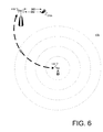
- FIG. 6 is a diagram showing the device in yet another zone from FIG. 1 .
- FIG. 7 is a diagram showing two mobile devices in the same zone, where both devices uplink in the same time-frequency slots but to different base stations.
- FIG. 8 is a diagram showing a mobile device uplinking with two separate base stations, but using different time-frequency slots for the two uplinks.
- one embodiment of the user equipment comprises a processor that determines an optimal downlink base station.
- the processor also determines an optimal uplink base station.
- the optimal uplink base station is determined independently of the optimal downlink base station, thereby allowing the user equipment to downlink with the optimal downlink base station and uplink with the optimal uplink base station.
- a receiver on the user equipment receives data from the optimal downlink base station while a transmitter on the user equipment transmits data to the optimal uplink base station.
- the optimal downlink base station is the same as the optimal uplink base station, the user equipment uplinks and downlinks to the same base station.
- Another aspect of this disclosure is a method for decoupling uplink and downlink determinations.
- the user equipment listens for available base stations and monitors the signal strengths of each of the base stations. Based on the monitored signal strengths, the user equipment independently determines the optimal downlink base station and the optimal uplink base station. For some embodiments, the optimal uplink base station is determined as a function of downlink signal strength and path loss.
- FIG. 1 is a diagram showing different zones 130, 140, 150, 160, 170 of differing signal strengths.
- FIG. 1 shows only two base stations 110, 120, with one base station (BS) being a macro-BS 110 and the other base station being a femto-BS 120.
- the femto-BS 120 is communicatively coupled to the macro-BS 110 by a backhaul 180, which permits data exchange between the femto-BS 120 and the macro-BS 110.
- the signal strength from the femto-BS 120 correspondingly diminishes as a function of the radial distance.
- the femto-BS 120 will have a greater effect on a zone 130 (referred to herein as "Zone-A” 130) that is closer to the femto-BS 120 than it will on any other zone 140, 150, 160, 170 (referred to in increasing distance from the femto-BS 120 as "Zone-B" 140, "Zone-C” 150, "Zone-D” 160, and “Zone-E” 170) that is farther away from the femto-BS.
- FIG. 2 is a diagram showing a mobile device 210a that is operating in Zone-A 130, which is the closest zone to the femto-BS 120.
- the device 210a listens for available base stations 110, 120 and monitors signal strengths from each of the available base stations (e.g., femto-BS 120 and macro-BS 110). From the monitored signal strengths, the device 210a determines whether the femto-BS 120 provides an optimal downlink (DL) to the device 210a, or whether the macro-BS 110 provides an optimal DL to the device 210a.
- DL downlink
- One way of determining the optimal DL BS is by simply selecting the BS as a function of DL signal strength.
- the femto-BS 120 (rather than the macro-BS 110) has greater DL signal strength and, therefore, is determined to be the optimal DL BS.
- a downlink (DL) 240 is established between the device 210a and the femto-BS 120. This DL 240 allows a receiver in the device 210a to DL with the femto-BS 120 and receive data from the femto-BS 120.
- the device 210a determines whether the femto-BS 120 provides an optimal uplink (UL) to the device 210a, or whether the macro-BS 110 provides an optimal UL to the device 210a. Again, since the device 210a is in Zone-A 130, the femto-BS 120 (rather than the macro-BS 110) is determined to be the optimal UL BS. Consequently, uplink (UL) 260 is established between the device 210a and the femto-BS 120. The UL 260 allows a transmitter in the device 210a to uplink to the femto-BS 120 and transmit data to the femto-BS 120.
- UL uplink
- the device 210a determines path losses from each of the available BS 110, 120.
- One way of determining path loss is by subtracting a measured signal strength at the device 210a from the transmit power of each BS.
- the path loss for each BS is then used as a proxy for UL signal strength, and the UL signal strength is then used as a basis for determining which BS is optimal for UL from the device 210a.
- a processor within the device 210a determines the DL signal strength and also the received signal strength, and then calculates the path loss as a function of the DL signal strength and the received signal strength.
- An optimal UL BS is then determined as a function of the path loss.
- FIG. 3 is a diagram showing a mobile device 210b that is operating in Zone-B 140, which is more radially-distant from the femto-BS 120 than Zone-A 130. Similar to the process described with reference to FIG. 2 , the device 210b listens for available base stations 110, 120 and monitors signal strengths from each available BS in order to determine whether the femto-BS 120 or the macro-BS 110 is the optimal BS for uplinking and downlinking. Unlike FIG. 2 , the device 210b, which is now in Zone-B 140, now determines that both the femto-BS 120 and the macro-BS 110 are acceptable for downlinking.
- DL 240 is established between the device 210b and the femto-BS 120, and DL 340 is also established between the device 210b and the macro-BS 110.
- DL 240, 340 enhancement of DL data throughput is achieved.
- the device 210b again, independently determines whether the femto-BS 120 provides an optimal uplink (UL) to the device 210b, or whether the macro-BS 110 provides an optimal UL to the device 210b.
- UL uplink
- the device 210b in Zone-B 140 favors uplinking with the femto-BS 120 (rather than the macro-BS 110). Consequently, UL 260 is established between the device 210b and the femto-BS 120.
- the mobile device 210b (or any other user equipment) can selectively UL and DL with different BS, thereby enhancing data throughput.
- FIG. 4 is a diagram showing a mobile device 210c that is operating in Zone-C 150, which is more radially-distant from the femto-BS 120 than either Zone-A 130 or Zone-B 140. This can happen when the mobile device of FIG. 3 migrates from Zone-B 130 into Zone-C 150. Similar to the processes described with reference to FIGS. 2 and 3 , the mobile device 210c again listens for available base stations 110, 120 and monitors signal strengths from each available BS in order to independently determine which BS is the optimal UL BS and which BS is the optimal DL BS.
- the device 210c determines that the macro-BS 110 is the optimal DL BS. As such, DL 340 is established between the device 210c and the macro-BS 110. Specifically, if the device 210c has migrated into Zone-C 150 from Zone-B 140, then the device 210c maintains its DL 340 with the macro-BS 110, but severs the DL 240 with the femto-BS 120.
- the device 210c determines which of the available BS is the optimal UL BS. Similar to FIG. 3 , the device 210c in Zone-C 150 determines that the femto-BS 120 (rather than the macro-BS 110) is the optimal UL BS. Consequently, UL 260 is maintained between the device 210c and the femto-BS 120. By decoupling the UL and DL , the mobile device 210c (or any other user equipment) can now UL with an optimal UL BS (such as the femto-BS 120 in this example), which may be different from an optimal DL BS (such as the macro-BS 110 in this example).
- an optimal UL BS such as the femto-BS 120 in this example
- one BS need not simultaneously handoff (HO) both the UL and the DL as the device 210c migrates from one zone (e.g., Zone-B 140) to another (e.g., Zone-C 150).
- zone-B 140 e.g., Zone-B 140
- Zone-C 150 e.g., Zone-C 150
- FIGS. 2 and 3 there is no DL from the femto-BS 120 to the device 210c for the embodiment of FIG. 4 . Additionally, there is no UL from the device 210c to the macro-BS 110.
- scheduling occurs in the DL. In other words, for every UL, the standards require a DL for ACK/NACK.
- UL 260 data between the device 210c and the femto-BS 120 is conveyed from the femto-BS 120 to the macro-BS 110 through the backhaul 180.
- the macro-BS 110 is now able to close the loop to the device 210c and provide ACK/NACK to the device 210c through the DL 340.
- FIG. 5 is a diagram showing a mobile device 210d that is operating in Zone-D 160, which is more radially-distant from the femto-BS 120 than Zone-C 150.
- the device 210d listens for available base stations 110, 120 and monitors signal strengths from each available BS in order to determine which BS is the optimal DL BS and which BS is the optimal UL BS.
- the device 210d which is now in Zone-D 160, determines whether the femto-BS 120 provides an optimal DL to the device 210d, or whether the macro-BS 110 provides an optimal DL to the device 210d.
- FIG. 5 is a diagram showing a mobile device 210d that is operating in Zone-D 160, which is more radially-distant from the femto-BS 120 than Zone-C 150.
- the device 210d in Zone-D 160 favors downlinking with the macro-BS 110 (rather than the femto-BS 120). Consequently, DL 340 is established between the device 210d and the macro-BS 110.
- the device 210d in Zone-D 160 determines that UL to both BS 110, 120 are acceptable.
- both UL 260 (between the device 210d and the femto-BS 120) and UL 560 (between the device 210d and the macro-BS 110) are established.
- the UL throughput is now increased.
- the macro-BS 110 can multiplex the ACK/NACK and transmit the multiplexed data through the single DL 340, back to the device 210d.
- FIG. 6 is a diagram showing a mobile device 210e that is operating in Zone-E 170, which is the farthest zone from the femto-BS 120.
- the device 210e listens for available base stations 110, 120 and monitors signal strengths from each of the available base stations (e.g., femto-BS 120 and macro-BS 110). From the monitored signal strengths, the device 210e determines whether the femto-BS 120 provides an optimal DL to the device 210e, or whether the macro-BS 110 provides an optimal DL to the device 210e.
- the macro-BS 110 (rather than the femto-BS 120) is determined to be the optimal DL BS. This is because the femto-BS 120 is sufficiently distant from the device 210e. As such, DL 340 is established between the device 210e and the macro-BS 110.
- the device 210e determines whether the femto-BS 120 provides an optimal UL to the device 210e, or whether the macro-BS 110 provides an optimal UL to the device 210e. Again, since the device 210e is in Zone-E 170, the macro-BS 110 (rather than the femto-BS 120) is determined to be the optimal UL BS. Consequently, UL 260 is established between the device 210e and the macro-BS 110.
- FIG. 7 is a diagram showing two mobile devices 720, 730 in the same zone 710, where both devices uplink in the same time-frequency slots but to different base stations.
- the two BS 110, 120 are designated as a macro-BS 110 and a femto-BS 120
- the two mobile devices 720, 730 are designated as a cellular telephone 720 and a smart phone 730.
- the cellular telephone 720 is located closer to the femto-BS 120 and farther from the macro-BS 110 than the smart phone 730.
- the smart phone 730 is located closer to the macro-BS 110 and farther from the femto-BS 120 than the cellular telephone 720.
- the cellular telephone 720 and the smart phone 720 are allocated the same time-frequency transmission slots for their respective uplinks. This allocation of the same time-frequency transmission slots for both devices 720, 730 prohibits the two devices 720, 730 from uplinking to the same base station.
- Separate uplinking of both devices 720, 730 can be accomplished by selectively setting transmission power levels for both the cellular telephone 720 and the smart phone 730, based on the distances between the devices 720, 730 and the BS 110, 120.
- the distances can be measured using global positioning system (GPS) coordinates of the devices 720, 730, or by some other user-equipment-position-tracking scheme based on the DL measurements reported by the devices 720, 730.
- GPS global positioning system
- the following example uses DL measurements reported by the devices 720, 730.
- the smart phone 730 since the smart phone 730 is closer to the macro-BS 110 than the cellular telephone 720, the smart phone 730 will report a stronger DL measurement to the macro-BS 110, while the cellular telephone 720 will report a weaker DL measurement to the macro-BS 110.
- the transmit power level of the cellular telephone 720 can be set so that it is sufficiently weak that it will not be received at the macro-BS 110. This allows the cellular telephone 720 to establish DL 340a with the macro-BS 110 and an UL 260 with the femto-BS 120.
- the ACK/NACK is conveyed back to the cellular telephone 720 in a process similar to that described with reference to FIG. 4 .
- the DL measurement reported by the smart phone 730 is used to set the transmit power level of the smart phone 730 such that the transmit power is insufficient to UL with the femto-BS 120, which is farther from the smart phone 720 and closer to the cellular telephone 720.
- the selective adjustment of transmit power levels for the cellular telephone 720 and the smart phone 730 allows both devices 720, 730 to UL with their respective BS 120, 110 using the same time-frequency transmission slots.
- FIG. 8 is a diagram showing a mobile device 210h uplinking with two separate base stations 810, 820, but using different time-frequency slots for the two uplinks.
- the femto-BS 820 of FIG. 8 is a receive-only BS 820.
- the receive-only BS 820 comprises multiple femto-BS, which serve as remote radio heads.
- the macro-BS 810 operates over a first carrier frequency bandwidth (Carrier-1), while the receive-only BS 820 operates over a second carrier frequency bandwidth (Carrier-2).
- Carrier-1 first carrier frequency bandwidth
- Carrier-2 second carrier frequency bandwidth
- the embodiment of FIG. 8 uses carrier aggregation.
- the UL is decoupled from the DL.
- DL 340 is established between the macro-BS 810 and the mobile device 210h over Carrier-1.
- UL 860 is established between the macro-BS 810 and the device 210h over Carrier-1, while UL 260 is established between the receive-only BS 820 and the device 210h over Carrier-2.
- MCS modulation and coding scheme
- the decoupling of UL and DL provides a variety of advantages. Additionally, the non-obvious nature of the disclosed embodiments is evidenced by the fact that all of the current industry standards relating to handoffs of user equipment prohibit decoupling of UL and DL, thereby requiring UL and DL handoffs to occur simultaneously. Additionally, insofar as the decoupling UL and DL are prohibited by the industry standards for handoffs, application of the industry standards for user-equipment handoffs would render the disclosed systems and methods inoperable. Furthermore, the disclosed embodiments change the basic principle under which the industry standards for handoffs are designed to operate.
- the various functions of the processor may be implemented in hardware, software, firmware, or a combination thereof.
- the functions of the processor are implemented in software or firmware that is stored in a memory and that is executed by a suitable instruction execution system.
- the functions of the processor can be implemented with any or a combination of the following technologies, which are all well known in the art: a discrete logic circuit(s) having logic gates for implementing logic functions upon data signals, an application specific integrated circuit (ASIC) having appropriate combinational logic gates, a programmable gate array(s) (PGA), a field programmable gate array (FPGA), etc.
- the processor functions which comprise an ordered listing of executable instructions for implementing logical functions, can be embodied in any computer-readable medium for use by or in connection with an instruction execution system, apparatus, or device, such as a computer-based system, processor-containing system, or other system that can fetch the instructions from the instruction execution system, apparatus, or device and execute the instructions.
- a "computer-readable medium” can be any means that can contain, store, communicate, propagate, or transport the program for use by or in connection with the instruction execution system, apparatus, or device.
- the computer-readable medium can be, for example but not limited to, an electronic, magnetic, optical, electromagnetic, infrared, or semiconductor system, apparatus, device, or propagation medium.
- the computer-readable medium would include the following: an electrical connection (electronic) having one or more wires, a portable computer diskette (magnetic), a random access memory (RAM) (electronic), a read-only memory (ROM) (electronic), an erasable programmable read-only memory (EPROM or Flash memory) (electronic), an optical fiber (optical), and a portable compact disc read-only memory (CDROM) (optical).
- an electrical connection having one or more wires
- a portable computer diskette magnetic
- RAM random access memory
- ROM read-only memory
- EPROM or Flash memory erasable programmable read-only memory
- CDROM portable compact disc read-only memory
- the computer-readable medium could even be paper or another suitable medium upon which the program is printed, as the program can be electronically captured via, for instance, optical scanning of the paper or other medium, then compiled, interpreted or otherwise processed in a suitable manner if necessary, and then stored in a computer memory.
Landscapes
- Engineering & Computer Science (AREA)
- Computer Networks & Wireless Communication (AREA)
- Signal Processing (AREA)
- Computer Security & Cryptography (AREA)
- Mobile Radio Communication Systems (AREA)
Abstract
The present disclosure provides systems and methods for decoupling downlinks and uplinks between user equipment (UE) and base stations. Briefly described, in architecture, one embodiment of the system comprises UE (e.g., cellular telephones, mobile devices, etc.) for independently establishing an uplink (UL) and a downlink (DL). One embodiment of the method comprises the steps of establishing a DL to an optimal DL base station (BS), and establishing an UL to an optimal UL BS.
Description
- This disclosure relates generally to telecommunications, and more particularly to handoff and cellular site selection.
- In a telecommunications network (e.g., cellular networks, etc.), user equipment (e.g., cellular telephone, mobile device, etc.) establishes a communication link with a base station (e.g., cell site). This communication link allows transmission of data to the base station (uplink) and, also, reception of data from the base station (downlink).
- Standard-setting bodies within various telecommunications industries have promulgated standards for how user equipment (UE) is required to uplink (UL) and downlink (DL) to base stations. These standards require the user equipment to UL and DL with the same base station (BS). Thus, when the UE migrates out of range from one BS and into range of another BS, the standards require simultaneous handoff (or handover) of both the UL and DL from one BS to another. This simultaneous handoff (HO) of both the UL and DL has its limitations.
- The present disclosure provides systems and methods for decoupling downlinks and uplinks between user equipment (UE) and base stations. Briefly described, in architecture, one embodiment of the system comprises UE for independently establishing an uplink (UL) and a downlink (DL). One embodiment of the method comprises the steps of establishing a DL to an optimal DL base station (BS), and establishing an UL to an optimal UL BS.
- According to an aspect, a method comprises:
- listening for available base stations;
- monitoring signal strengths of each of the available base stations;
- determining an optimal downlink base station from the available base stations based on the monitored signal strengths;
- determining an optimal uplink base station from the available base stations based on the monitored signal strengths;
- establishing a downlink to the optimal downlink base station; and
- establishing an uplink to the optimal uplink base station.
- Advantageously, the step of determining an optimal uplink base station comprises the steps of:
- determining path losses for each of the available base stations;
- estimating uplink signal strengths for each of the available base stations based on the determined path losses; and
- selecting the optimal uplink base station based on the estimated uplink signal strengths.
- According to an aspect, a user equipment comprises:
- a processor for determining an optimal downlink base station, the processor for further determining an optimal uplink base station, the optimal uplink base station being determined independently of the optimal downlink base station;
- a receiver for downlinking with the optimal downlink base station; and
- a transmitter for uplinking with the optimal uplink base station.
- Advantageously, the optimal downlink base station being different from the optimal uplink base station.
- Advantageously, the optimal downlink base station being a serving downlink base station, the optimal uplink base station being a serving uplink base station.
- Advantageously, the processor for further determining a downlink signal strength.
- Advantageously, the processor for further determining downlink transmit signal strengths of multiple base stations.
- Advantageously, the processor for further determining downlink transmit signal strengths of multiple base stations, the multiple base stations operating under multiple radio access technologies.
- Advantageously, the processor for further determining a received signal strength.
- Advantageously, the processor for further calculating a path loss based on location coordinates.
- Advantageously, the processor for further calculating a path loss as a function of the downlink signal strength, the received signal strength, a downlink frequency, and an uplink frequency.
- Advantageously, the optimal uplink base station being determined as a function of the path loss.
- Advantageously, the optimal downlink base station being determined as a function of the received signal strength.
- Advantageously, the transmitter for further establishing an uplink with the optimal downlink base station.
- Advantageously, the transmitter further for transmitting uplink control messages to the optimal downlink base station, the transmitter further for transmitting uplink data to the optimal uplink base station.
- Advantageously, the transmitter for further establishing an uplink with the optimal downlink base station, the optimal downlink base station being different from the optimal uplink base station.
- Advantageously, the transmitter for further transmitting uplink data to both the optimal uplink base station and the optimal downlink base station.
- According to an aspect, a method comprises:
- monitoring signals from base stations;
- determining an optimal downlink base station based on the monitored signals;
- determining an optimal uplink base station based on the monitored signals;
- establishing a downlink to the optimal downlink base station; and
- establishing an uplink to the optimal uplink base station.
- Advantageously, the step of monitoring signals from base stations comprising:
- receiving signals from the base stations; and
- measuring signal strengths corresponding to each of the received signals.
- Advantageously, the step of determining the optimal downlink base station comprising:
- determining a strongest downlink signal from the measured signal strengths; and
- selecting the optimal downlink base station based on the strongest downlink signal.
- Advantageously, the step of determining the optimal uplink base station comprising:
- determining a downlink signal strength for each of the base stations based on the received signals;
- determining a received signal strength for each of the base stations from the received signals;
- calculating a path loss as a function of the downlink signal strength and the received signal strength;
- determining a strongest uplink signal as a function of the path loss; and
- selecting the optimal uplink base station based on the strongest uplink signal.
- Advantageously, the method further comprising:
- establishing a control-message uplink to the optimal downlink base station.
- Advantageously, the method further comprising:
- transmitting uplink data to the optimal uplink base station; and
- transmitting uplink control messages to the optimal downlink base station.
- Advantageously, the method further comprising:
- transmitting uplink data to the optimal downlink base station.
- Advantageously, the method further comprising:
- combining uplink data to the optimal uplink base station with the uplink data to the optimal downlink base station.
- Other systems, devices, methods, features, and advantages will be or become apparent to one with skill in the art upon examination of the following drawings and detailed description. It is intended that all such additional systems, methods, features, and advantages be included within this description, be within the scope of the present disclosure, and be protected by the accompanying claims.
- Many aspects of the disclosure can be better understood with reference to the following drawings. The components in the drawings are not necessarily to scale, emphasis instead being placed upon clearly illustrating the principles of the present disclosure. Moreover, in the drawings, like reference numerals designate corresponding parts throughout the several views.
-
FIG. 1 is a diagram showing different zones having different signal strengths. -
FIG. 2 is a diagram showing a mobile device in one zone fromFIG. 1 . -
FIG. 3 is a diagram showing the device in another zone fromFIG. 1 . -
FIG. 4 is a diagram showing the device in yet another zone fromFIG. 1 . -
FIG. 5 is a diagram showing the device in yet another zone fromFIG. 1 . -
FIG. 6 is a diagram showing the device in yet another zone fromFIG. 1 . -
FIG. 7 is a diagram showing two mobile devices in the same zone, where both devices uplink in the same time-frequency slots but to different base stations. -
FIG. 8 is a diagram showing a mobile device uplinking with two separate base stations, but using different time-frequency slots for the two uplinks. - Industry standards prohibit user equipment (such as cellular telephones and other mobile devices) from simultaneously establishing an uplink to one base station (such as a cell site) and a downlink to another base station as a part of cellular site selection or handoff. Thus, when a cellular telephone switches from one cell site to another cell site, the standards require simultaneous handoff for both the uplink and the downlink. Thus, even though one cell site may be more optimal for downlink and a different cell site may be more optimal for uplink, the cellular telephone cannot downlink with one cell site and uplink with another cell site.
- The systems and methods described herein overcome such a limitation by decoupling downlinks and uplinks so that the user equipment may downlink with one base station while uplinking with another base station. Given this, one embodiment of the user equipment comprises a processor that determines an optimal downlink base station. The processor also determines an optimal uplink base station. The optimal uplink base station is determined independently of the optimal downlink base station, thereby allowing the user equipment to downlink with the optimal downlink base station and uplink with the optimal uplink base station. Once the downlink and uplink are established, a receiver on the user equipment receives data from the optimal downlink base station while a transmitter on the user equipment transmits data to the optimal uplink base station. In the event that the optimal downlink base station is the same as the optimal uplink base station, the user equipment uplinks and downlinks to the same base station.
- Another aspect of this disclosure is a method for decoupling uplink and downlink determinations. In one embodiment of the method, the user equipment listens for available base stations and monitors the signal strengths of each of the base stations. Based on the monitored signal strengths, the user equipment independently determines the optimal downlink base station and the optimal uplink base station. For some embodiments, the optimal uplink base station is determined as a function of downlink signal strength and path loss.
- With this overview in mind, reference is now made in detail to the description of the embodiments as illustrated in the drawings. While several embodiments are described in connection with these drawings, there is no intent to limit the disclosure to the embodiment or embodiments disclosed herein. On the contrary, the intent is to cover all alternatives, modifications, and equivalents.
-
FIG. 1 is a diagram showingdifferent zones FIG. 1 shows only twobase stations BS 120. The femto-BS 120 is communicatively coupled to the macro-BS 110 by abackhaul 180, which permits data exchange between the femto-BS 120 and themacro-BS 110. - As shown in
FIG. 1 , as radial distances from the femto-BS 120 increase, the signal strength from the femto-BS 120 correspondingly diminishes as a function of the radial distance. In other words, the femto-BS 120 will have a greater effect on a zone 130 (referred to herein as "Zone-A" 130) that is closer to the femto-BS 120 than it will on anyother zone BS 120 as "Zone-B" 140, "Zone-C" 150, "Zone-D" 160, and "Zone-E" 170) that is farther away from the femto-BS. -
FIG. 2 is a diagram showing amobile device 210a that is operating in Zone-A 130, which is the closest zone to the femto-BS 120. As shown inFIG. 2 , thedevice 210a listens foravailable base stations BS 120 and macro-BS 110). From the monitored signal strengths, thedevice 210a determines whether the femto-BS 120 provides an optimal downlink (DL) to thedevice 210a, or whether themacro-BS 110 provides an optimal DL to thedevice 210a. One way of determining the optimal DL BS is by simply selecting the BS as a function of DL signal strength. Insofar as thedevice 210a is in Zone-A 130, the femto-BS 120 (rather than the macro-BS 110) has greater DL signal strength and, therefore, is determined to be the optimal DL BS. As such, a downlink (DL) 240 is established between thedevice 210a and the femto-BS 120. ThisDL 240 allows a receiver in thedevice 210a to DL with the femto-BS 120 and receive data from the femto-BS 120. - Independent of the DL determination, the
device 210a determines whether the femto-BS 120 provides an optimal uplink (UL) to thedevice 210a, or whether themacro-BS 110 provides an optimal UL to thedevice 210a. Again, since thedevice 210a is in Zone-A 130, the femto-BS 120 (rather than the macro-BS 110) is determined to be the optimal UL BS. Consequently, uplink (UL) 260 is established between thedevice 210a and the femto-BS 120. TheUL 260 allows a transmitter in thedevice 210a to uplink to the femto-BS 120 and transmit data to the femto-BS 120. - In determining the optimal UL BS, the
device 210a determines path losses from each of theavailable BS device 210a from the transmit power of each BS. The path loss for each BS is then used as a proxy for UL signal strength, and the UL signal strength is then used as a basis for determining which BS is optimal for UL from thedevice 210a. In other words, a processor within thedevice 210a determines the DL signal strength and also the received signal strength, and then calculates the path loss as a function of the DL signal strength and the received signal strength. An optimal UL BS is then determined as a function of the path loss. -
FIG. 3 is a diagram showing amobile device 210b that is operating in Zone-B 140, which is more radially-distant from the femto-BS 120 than Zone-A 130. Similar to the process described with reference toFIG. 2 , thedevice 210b listens foravailable base stations BS 120 or themacro-BS 110 is the optimal BS for uplinking and downlinking. UnlikeFIG. 2 , thedevice 210b, which is now in Zone-B 140, now determines that both the femto-BS 120 and the macro-BS 110 are acceptable for downlinking. As such,DL 240 is established between thedevice 210b and the femto-BS 120, andDL 340 is also established between thedevice 210b and themacro-BS 110. By establishing twoDL - The
device 210b, again, independently determines whether the femto-BS 120 provides an optimal uplink (UL) to thedevice 210b, or whether themacro-BS 110 provides an optimal UL to thedevice 210b. InFIG. 3 , due to the distance between thedevice 210b and themacro-BS 110, thedevice 210b in Zone-B 140 favors uplinking with the femto-BS 120 (rather than the macro-BS 110). Consequently,UL 260 is established between thedevice 210b and the femto-BS 120. - As one can appreciate, since the DL-decision and UL-decision are now decoupled, the
mobile device 210b (or any other user equipment) can selectively UL and DL with different BS, thereby enhancing data throughput. -
FIG. 4 is a diagram showing amobile device 210c that is operating in Zone-C 150, which is more radially-distant from the femto-BS 120 than either Zone-A 130 or Zone-B 140. This can happen when the mobile device ofFIG. 3 migrates from Zone-B 130 into Zone-C 150. Similar to the processes described with reference toFIGS. 2 and3 , themobile device 210c again listens foravailable base stations - Unlike
FIG. 2 , thedevice 210c, which is now operating in Zone-C 150, determines that themacro-BS 110 is the optimal DL BS. As such,DL 340 is established between thedevice 210c and themacro-BS 110. Specifically, if thedevice 210c has migrated into Zone-C 150 from Zone-B 140, then thedevice 210c maintains itsDL 340 with the macro-BS 110, but severs theDL 240 with the femto-BS 120. - Independent of its DL determination, the
device 210c determines which of the available BS is the optimal UL BS. Similar toFIG. 3 , thedevice 210c in Zone-C 150 determines that the femto-BS 120 (rather than the macro-BS 110) is the optimal UL BS. Consequently,UL 260 is maintained between thedevice 210c and the femto-BS 120. By decoupling the UL and DL , themobile device 210c (or any other user equipment) can now UL with an optimal UL BS (such as the femto-BS 120 in this example), which may be different from an optimal DL BS (such as the macro-BS 110 in this example). Additionally, since the UL and DL determinations are independent of each other, one BS need not simultaneously handoff (HO) both the UL and the DL as thedevice 210c migrates from one zone (e.g., Zone-B 140) to another (e.g., Zone-C 150). - Unlike
FIGS. 2 and3 , there is no DL from the femto-BS 120 to thedevice 210c for the embodiment ofFIG. 4 . Additionally, there is no UL from thedevice 210c to themacro-BS 110. According to current industry standards, scheduling occurs in the DL. In other words, for every UL, the standards require a DL for ACK/NACK. Thus, in order for the scheduling to properly occur,UL 260 data between thedevice 210c and the femto-BS 120 is conveyed from the femto-BS 120 to the macro-BS 110 through thebackhaul 180. Themacro-BS 110 is now able to close the loop to thedevice 210c and provide ACK/NACK to thedevice 210c through theDL 340. -
FIG. 5 is a diagram showing amobile device 210d that is operating in Zone-D 160, which is more radially-distant from the femto-BS 120 than Zone-C 150. Once again, thedevice 210d listens foravailable base stations FIG. 5 , thedevice 210d, which is now in Zone-D 160, determines whether the femto-BS 120 provides an optimal DL to thedevice 210d, or whether themacro-BS 110 provides an optimal DL to thedevice 210d. InFIG. 5 , due to the distance between thedevice 210d and the femto-BS 120, thedevice 210d in Zone-D 160 favors downlinking with the macro-BS 110 (rather than the femto-BS 120). Consequently,DL 340 is established between thedevice 210d and themacro-BS 110. - As for the UL determination, the
device 210d in Zone-D 160 determines that UL to bothBS device 210d and the femto-BS 120) and UL 560 (between thedevice 210d and the macro-BS 110) are established. By establishing twoUL - Similar to
FIG. 4 , there is no DL from the femto-BS 120 to thedevice 210d for the embodiment ofFIG. 5 . Since every UL requires a DL for ACK/NACK for proper scheduling,UL 260 data between thedevice 210c and the femto-BS 120 is conveyed from the femto-BS 120 to the macro-BS 110 through thebackhaul 180. Similar toFIG. 4 , themacro-BS 110 ofFIG. 5 is now able to close the loop to thedevice 210c through thebackhaul 180. Since ACK/NACK for bothUL 260 andUL 560 are provided through asingle DL 340, the macro-BS 110 can multiplex the ACK/NACK and transmit the multiplexed data through thesingle DL 340, back to thedevice 210d. -
FIG. 6 is a diagram showing amobile device 210e that is operating in Zone-E 170, which is the farthest zone from the femto-BS 120. As shown inFIG. 6 , thedevice 210e listens foravailable base stations BS 120 and macro-BS 110). From the monitored signal strengths, thedevice 210e determines whether the femto-BS 120 provides an optimal DL to thedevice 210e, or whether themacro-BS 110 provides an optimal DL to thedevice 210e. Insofar as thedevice 210e is in Zone-E 170, the macro-BS 110 (rather than the femto-BS 120) is determined to be the optimal DL BS. This is because the femto-BS 120 is sufficiently distant from thedevice 210e. As such,DL 340 is established between thedevice 210e and themacro-BS 110. - Independent of the DL determination, the
device 210e determines whether the femto-BS 120 provides an optimal UL to thedevice 210e, or whether themacro-BS 110 provides an optimal UL to thedevice 210e. Again, since thedevice 210e is in Zone-E 170, the macro-BS 110 (rather than the femto-BS 120) is determined to be the optimal UL BS. Consequently,UL 260 is established between thedevice 210e and themacro-BS 110. -
FIG. 7 is a diagram showing twomobile devices same zone 710, where both devices uplink in the same time-frequency slots but to different base stations. For illustrative purposes, the twoBS BS 120, and the twomobile devices cellular telephone 720 and asmart phone 730. In the embodiment ofFIG. 7 , thecellular telephone 720 is located closer to the femto-BS 120 and farther from the macro-BS 110 than thesmart phone 730. Conversely, thesmart phone 730 is located closer to the macro-BS 110 and farther from the femto-BS 120 than thecellular telephone 720. However, in the embodiment ofFIG. 7 , thecellular telephone 720 and thesmart phone 720 are allocated the same time-frequency transmission slots for their respective uplinks. This allocation of the same time-frequency transmission slots for bothdevices devices - Separate uplinking of both
devices cellular telephone 720 and thesmart phone 730, based on the distances between thedevices BS devices devices devices - In the embodiment of
FIG. 7 , since thesmart phone 730 is closer to the macro-BS 110 than thecellular telephone 720, thesmart phone 730 will report a stronger DL measurement to themacro-BS 110, while thecellular telephone 720 will report a weaker DL measurement to themacro-BS 110. - From the DL measurement reported by the
cellular telephone 720, the transmit power level of thecellular telephone 720 can be set so that it is sufficiently weak that it will not be received at themacro-BS 110. This allows thecellular telephone 720 to establishDL 340a with the macro-BS 110 and anUL 260 with the femto-BS 120. The ACK/NACK is conveyed back to thecellular telephone 720 in a process similar to that described with reference toFIG. 4 . - Similarly, the DL measurement reported by the
smart phone 730 is used to set the transmit power level of thesmart phone 730 such that the transmit power is insufficient to UL with the femto-BS 120, which is farther from thesmart phone 720 and closer to thecellular telephone 720. The selective adjustment of transmit power levels for thecellular telephone 720 and thesmart phone 730 allows bothdevices respective BS -
FIG. 8 is a diagram showing amobile device 210h uplinking with twoseparate base stations BS 120 ofFIGS. 1 through 7 , the femto-BS 820 ofFIG. 8 is a receive-only BS 820. In one embodiment, the receive-only BS 820 comprises multiple femto-BS, which serve as remote radio heads. - In the embodiment of
FIG. 8 , themacro-BS 810 operates over a first carrier frequency bandwidth (Carrier-1), while the receive-only BS 820 operates over a second carrier frequency bandwidth (Carrier-2). As such, the embodiment ofFIG. 8 uses carrier aggregation. - In operation, the UL is decoupled from the DL. Thus,
DL 340 is established between the macro-BS 810 and themobile device 210h over Carrier-1. Independently,UL 860 is established between the macro-BS 810 and thedevice 210h over Carrier-1, whileUL 260 is established between the receive-only BS 820 and thedevice 210h over Carrier-2. This configuration allows thedevice 210h to use Carrier-2 for UL data transmission only. Thus, heavy UL data can be transmitted over Carrier-2 from thedevice 210h to the receive-only BS 820 at a high modulation and coding scheme (MCS). Concurrently, the embodiment ofFIG. 8 allows heavy DL data transmission from the macro-BS 810 to thedevice 210h over Carrier-1, while allowing for UL control data (e.g., DL ACK/NACK for UL data) transmission from thedevice 210h to the macro-BS 810 over Carrier-1. - As one having skill in the art can appreciate, the decoupling of UL and DL provides a variety of advantages. Additionally, the non-obvious nature of the disclosed embodiments is evidenced by the fact that all of the current industry standards relating to handoffs of user equipment prohibit decoupling of UL and DL, thereby requiring UL and DL handoffs to occur simultaneously. Additionally, insofar as the decoupling UL and DL are prohibited by the industry standards for handoffs, application of the industry standards for user-equipment handoffs would render the disclosed systems and methods inoperable. Furthermore, the disclosed embodiments change the basic principle under which the industry standards for handoffs are designed to operate.
- The various functions of the processor may be implemented in hardware, software, firmware, or a combination thereof. In the preferred embodiment(s), the functions of the processor are implemented in software or firmware that is stored in a memory and that is executed by a suitable instruction execution system. If implemented in hardware, as in an alternative embodiment, the functions of the processor can be implemented with any or a combination of the following technologies, which are all well known in the art: a discrete logic circuit(s) having logic gates for implementing logic functions upon data signals, an application specific integrated circuit (ASIC) having appropriate combinational logic gates, a programmable gate array(s) (PGA), a field programmable gate array (FPGA), etc.
- Any process descriptions or blocks in flow charts should be understood as representing modules, segments, or portions of code which include one or more executable instructions for implementing specific logical functions or steps in the process, and alternate implementations are included within the scope of the preferred embodiment of the present disclosure in which functions may be executed out of order from that shown or discussed, including substantially concurrently or in reverse order, depending on the functionality involved, as would be understood by those reasonably skilled in the art of the present disclosure.
- The processor functions, which comprise an ordered listing of executable instructions for implementing logical functions, can be embodied in any computer-readable medium for use by or in connection with an instruction execution system, apparatus, or device, such as a computer-based system, processor-containing system, or other system that can fetch the instructions from the instruction execution system, apparatus, or device and execute the instructions. In the context of this document, a "computer-readable medium" can be any means that can contain, store, communicate, propagate, or transport the program for use by or in connection with the instruction execution system, apparatus, or device. The computer-readable medium can be, for example but not limited to, an electronic, magnetic, optical, electromagnetic, infrared, or semiconductor system, apparatus, device, or propagation medium. More specific examples (a nonexhaustive list) of the computer-readable medium would include the following: an electrical connection (electronic) having one or more wires, a portable computer diskette (magnetic), a random access memory (RAM) (electronic), a read-only memory (ROM) (electronic), an erasable programmable read-only memory (EPROM or Flash memory) (electronic), an optical fiber (optical), and a portable compact disc read-only memory (CDROM) (optical). Note that the computer-readable medium could even be paper or another suitable medium upon which the program is printed, as the program can be electronically captured via, for instance, optical scanning of the paper or other medium, then compiled, interpreted or otherwise processed in a suitable manner if necessary, and then stored in a computer memory.
- Although exemplary embodiments have been shown and described, it will be clear to those of ordinary skill in the art that a number of changes, modifications, or alterations to the disclosure as described may be made. For example, while macro-BS and femto-BS have been used to illustrate various embodiments of the invention, it should be appreciated by one having ordinary skill in the art that the systems and methods can be extended to micro-BS, pico-BS, or other types of cell sites in heterogeneous networks. Additionally, while a mobile device has been used to illustrate various embodiments, it should be appreciated that the user equipment may be cellular telephones, smart phones, tablet computers, e-readers, or any other type of equipment that has the capability of downlinking and uplinking with a cell site. Additionally, while examples of cellular networks have been used to illustrate various embodiments, it should be appreciated that similar methods and systems can be used for UL and DL for two different radio access technologies (RAT). All such changes, modifications, and alterations should therefore be seen as within the scope of the disclosure.
Claims (15)
- A user equipment comprising:a processor for determining an optimal downlink base station, the processor for further determining an optimal uplink base station, the optimal uplink base station being determined independently of the optimal downlink base station;a receiver for downlinking with the optimal downlink base station; anda transmitter for uplinking with the optimal uplink base station.
- The user equipment of claim 1, the optimal downlink base station being different from the optimal uplink base station.
- The user equipment of claim 2, the optimal downlink base station being a serving downlink base station, the optimal uplink base station being a serving uplink base station.
- The user equipment of claim 1, the processor for further determining a downlink signal strength.
- The user equipment of claim 1, the processor for further determining downlink transmit signal strengths of multiple base stations.
- The user equipment of claim 1, the processor for further determining downlink transmit signal strengths of multiple base stations, the multiple base stations operating under multiple radio access technologies.
- The user equipment of claim 4, the processor for further determining a received signal strength.
- The user equipment of claim 7, the processor for further calculating a path loss based on location coordinates.
- The user equipment of claim 7, the processor for further calculating a path loss as a function of the downlink signal strength, the received signal strength, a downlink frequency, and an uplink frequency.
- The user equipment of claim 9, the optimal uplink base station being determined as a function of the path loss.
- The user equipment of claim 7, the optimal downlink base station being determined as a function of the received signal strength.
- The user equipment of claim 1, the transmitter for further establishing an uplink with the optimal downlink base station.
- A method comprising:monitoring signals from base stations;determining an optimal downlink base station based on the monitored signals;determining an optimal uplink base station based on the monitored signals;establishing a downlink to the optimal downlink base station; andestablishing an uplink to the optimal uplink base station.
- The method of claim 13, the step of monitoring signals from base stations comprising:receiving signals from the base stations; andmeasuring signal strengths corresponding to each of the received signals.
- A method comprising:listening for available base stations;monitoring signal strengths of each of the available base stations;determining an optimal downlink base station from the available base stations based on the monitored signal strengths;determining an optimal uplink base station from the available base stations based on the monitored signal strengths;establishing a downlink to the optimal downlink base station; andestablishing an uplink to the optimal uplink base station.
Applications Claiming Priority (1)
| Application Number | Priority Date | Filing Date | Title |
|---|---|---|---|
| US13/336,208 US9060351B2 (en) | 2011-12-23 | 2011-12-23 | Decoupled downlink and uplink |
Publications (1)
| Publication Number | Publication Date |
|---|---|
| EP2608607A2 true EP2608607A2 (en) | 2013-06-26 |
Family
ID=46796221
Family Applications (1)
| Application Number | Title | Priority Date | Filing Date |
|---|---|---|---|
| EP12005727.8A Withdrawn EP2608607A2 (en) | 2011-12-23 | 2012-08-07 | Decoupled downlink and uplink |
Country Status (5)
| Country | Link |
|---|---|
| US (2) | US9060351B2 (en) |
| EP (1) | EP2608607A2 (en) |
| KR (1) | KR101475051B1 (en) |
| CN (1) | CN103179681A (en) |
| TW (1) | TWI530203B (en) |
Cited By (6)
| Publication number | Priority date | Publication date | Assignee | Title |
|---|---|---|---|---|
| WO2015021318A3 (en) * | 2013-08-07 | 2015-04-09 | Interdigital Patent Holdings, Inc. | Coverage enhancements of low cost mtc devices in uplink/downlink decoupled scenario |
| EP2903343A1 (en) * | 2014-01-31 | 2015-08-05 | Alcatel Lucent | A method for ul-dl decoupling, low power node, network and computer program product |
| EP2836048A3 (en) * | 2013-08-08 | 2015-09-23 | Alcatel Lucent | Methods and apparatuses for decoupling uplink and downlink in a mobile communications network |
| CN108353337A (en) * | 2015-11-12 | 2018-07-31 | 特伦萨控股有限公司 | Method and device for transmitting data in a network |
| US10219296B2 (en) | 2016-12-07 | 2019-02-26 | Telefonaktiebolaget Lm Ericsson (Publ) | Decoupled downlink reception and uplink reception in a mixed licensed carrier and unlicensed carrier wireless communication system |
| WO2022186738A1 (en) * | 2021-03-01 | 2022-09-09 | Telefonaktiebolaget Lm Ericsson (Publ) | Setting power control configuration parameters in a communications network with decoupled dl and ul transmission |
Families Citing this family (11)
| Publication number | Priority date | Publication date | Assignee | Title |
|---|---|---|---|---|
| US9699701B2 (en) * | 2012-08-10 | 2017-07-04 | Qualcomm Incorporated | Mobility operation in LTE |
| GB2525659B (en) * | 2014-05-01 | 2020-11-25 | Vodafone Ip Licensing Ltd | Arrangement for choosing transceiver nodes in a mobile telecommunications network |
| WO2016088958A1 (en) * | 2014-12-04 | 2016-06-09 | 엘지전자 주식회사 | Method for transmitting fdr in wireless lan system and device therefor |
| WO2016201646A1 (en) * | 2015-06-17 | 2016-12-22 | 华为技术有限公司 | Method, device and system for acquiring uplink data transmission resource |
| KR102357669B1 (en) | 2015-06-22 | 2022-02-03 | 삼성전자주식회사 | Apparatus and method for transmitting/receiving signal based on traffic characteristics in mobile communication network |
| US10129052B2 (en) | 2015-08-14 | 2018-11-13 | Qualcomm Incorporated | Phase noise estimation |
| US11191097B2 (en) | 2015-08-17 | 2021-11-30 | Qualcomm Incorporated | Reception of multiple uplink control messages at a same time slot |
| EP3698591B1 (en) * | 2017-10-16 | 2026-02-18 | Sensus Spectrum, LLC | Method and apparatus for slotted-aloha collision improvement by population density timeslot selection per radio frequency propagation pathloss |
| US12120060B2 (en) * | 2018-09-19 | 2024-10-15 | Qualcomm Incorporated | Acknowledgement codebook design for multiple transmission reception points |
| JP7687532B2 (en) * | 2022-02-21 | 2025-06-03 | 日本電信電話株式会社 | Terminal, communication method, and wireless communication system |
| CN122476491A (en) * | 2025-01-27 | 2026-07-28 | 维沃移动通信有限公司 | Wireless connection establishment method, device, terminal, network side equipment and readable storage medium |
Family Cites Families (25)
| Publication number | Priority date | Publication date | Assignee | Title |
|---|---|---|---|---|
| SE9200915D0 (en) * | 1992-03-24 | 1992-03-24 | Ericsson Telefon Ab L M | METHODS IN A CELLULAR MOBILE RADIO COMMUNINCATION SYSTEM |
| US5809430A (en) * | 1994-06-03 | 1998-09-15 | Motorola, Inc. | Method and apparatus for base selection in a communication system |
| FI106287B (en) * | 1997-09-17 | 2000-12-29 | Nokia Mobile Phones Ltd | Improved procedure for changing base station |
| KR19990080484A (en) * | 1998-04-17 | 1999-11-15 | 김영환 | Hand off method of mobile communication system |
| US6295450B1 (en) * | 1998-06-23 | 2001-09-25 | Motorola, Inc. | Method and apparatus for transferring communication within a communication system |
| GB9911084D0 (en) * | 1999-05-12 | 1999-07-14 | Nokia Telecommunications Oy | Transmitting method |
| DE19928579A1 (en) | 1999-06-22 | 2001-01-11 | Siemens Ag | Alternating uplink / downlink transitions in channel allocation in a TDD transmission frame with multiple switching times |
| US7065063B2 (en) * | 2001-04-11 | 2006-06-20 | Research In Motion Limited | System and method for balancing communication traffic loading between adjacent base stations in a mobile communications network |
| US7756520B2 (en) * | 2001-10-17 | 2010-07-13 | Nortel Networks Limited | Packet communication system with dual candidate sets for independent management of uplink and downlink transmissions |
| US20030206532A1 (en) | 2002-05-06 | 2003-11-06 | Extricom Ltd. | Collaboration between wireless lan access points |
| US6940843B2 (en) * | 2003-02-14 | 2005-09-06 | Cisco Technology, Inc. | Selecting an access point according to a measure of received signal quality |
| ATE463945T1 (en) * | 2004-02-13 | 2010-04-15 | Ericsson Telefon Ab L M | METHOD FOR FAST HARD HARD HARDWARDING AND MOBILE STATION AND BASE STATION SUPPORTING SUCH METHOD |
| US7983674B2 (en) * | 2005-06-16 | 2011-07-19 | Qualcomm Incorporated | Serving base station selection in a wireless communication system |
| US7813738B2 (en) * | 2005-08-11 | 2010-10-12 | Extricom Ltd. | WLAN operating on multiple adjacent bands |
| US7899004B2 (en) * | 2005-08-22 | 2011-03-01 | Qualcomm Incorporated | Distributed protocol over a wireless connection |
| EP1821429A3 (en) | 2005-10-26 | 2007-09-05 | Mitsubishi Electric Information Technology Centre Europe B.V. | Method and apparatus for communicating downlink and uplink sub-frames in a half duplex communication system |
| US7672282B1 (en) | 2005-11-21 | 2010-03-02 | Marvell International Ltd. | BSS selection using path loss |
| US8160629B2 (en) * | 2006-09-07 | 2012-04-17 | Airvana, Corp. | Controlling reverse link interference in private access points for wireless networking |
| US20080200202A1 (en) * | 2007-02-13 | 2008-08-21 | Qualcomm Incorporated | Power control with link imbalance on downlink and uplink |
| KR101356505B1 (en) * | 2007-06-18 | 2014-02-03 | 엘지전자 주식회사 | Method for performing downlik/uplink handover |
| JP5173626B2 (en) * | 2008-06-23 | 2013-04-03 | 株式会社エヌ・ティ・ティ・ドコモ | Centralized control base station and signal control method |
| US8139535B2 (en) * | 2008-10-31 | 2012-03-20 | Intel Corporation | Blind channel detection techniques |
| JP5310401B2 (en) * | 2009-09-01 | 2013-10-09 | 富士通株式会社 | Base station, communication system and communication method |
| US9001784B2 (en) * | 2010-09-09 | 2015-04-07 | Qualcomm Incorporated | Handover of multimode user equipment between radio access technologies for reduced call setup time |
| US8849339B2 (en) * | 2011-08-12 | 2014-09-30 | Telefonaktiebolaget L M Ericsson (Publ) | Closed loop power control in a heterogeneous network by selecting among sets of accumulative power step values |
-
2011
- 2011-12-23 US US13/336,208 patent/US9060351B2/en active Active
-
2012
- 2012-08-07 EP EP12005727.8A patent/EP2608607A2/en not_active Withdrawn
- 2012-09-12 TW TW101133325A patent/TWI530203B/en active
- 2012-09-19 KR KR1020120104045A patent/KR101475051B1/en active Active
- 2012-09-24 CN CN2012103598357A patent/CN103179681A/en active Pending
-
2015
- 2015-05-08 US US14/708,121 patent/US10425919B2/en active Active
Non-Patent Citations (1)
| Title |
|---|
| None |
Cited By (8)
| Publication number | Priority date | Publication date | Assignee | Title |
|---|---|---|---|---|
| WO2015021318A3 (en) * | 2013-08-07 | 2015-04-09 | Interdigital Patent Holdings, Inc. | Coverage enhancements of low cost mtc devices in uplink/downlink decoupled scenario |
| US11470619B2 (en) | 2013-08-07 | 2022-10-11 | Interdigital Patent Holdings, Inc. | Coverage enhancements of low cost MTC devices in uplink/downlink decoupled scenario |
| EP2836048A3 (en) * | 2013-08-08 | 2015-09-23 | Alcatel Lucent | Methods and apparatuses for decoupling uplink and downlink in a mobile communications network |
| EP2903343A1 (en) * | 2014-01-31 | 2015-08-05 | Alcatel Lucent | A method for ul-dl decoupling, low power node, network and computer program product |
| WO2015113863A1 (en) * | 2014-01-31 | 2015-08-06 | Alcatel Lucent | A method for ul-dl decoupling, low power node, network and computer program product |
| CN108353337A (en) * | 2015-11-12 | 2018-07-31 | 特伦萨控股有限公司 | Method and device for transmitting data in a network |
| US10219296B2 (en) | 2016-12-07 | 2019-02-26 | Telefonaktiebolaget Lm Ericsson (Publ) | Decoupled downlink reception and uplink reception in a mixed licensed carrier and unlicensed carrier wireless communication system |
| WO2022186738A1 (en) * | 2021-03-01 | 2022-09-09 | Telefonaktiebolaget Lm Ericsson (Publ) | Setting power control configuration parameters in a communications network with decoupled dl and ul transmission |
Also Published As
| Publication number | Publication date |
|---|---|
| TWI530203B (en) | 2016-04-11 |
| TW201328386A (en) | 2013-07-01 |
| KR20130073806A (en) | 2013-07-03 |
| US20130163441A1 (en) | 2013-06-27 |
| US10425919B2 (en) | 2019-09-24 |
| US20150245339A1 (en) | 2015-08-27 |
| US9060351B2 (en) | 2015-06-16 |
| KR101475051B1 (en) | 2014-12-22 |
| CN103179681A (en) | 2013-06-26 |
Similar Documents
| Publication | Publication Date | Title |
|---|---|---|
| US9060351B2 (en) | Decoupled downlink and uplink | |
| KR101967047B1 (en) | Method and apparatus for performing UE beamforming in a wireless communication system | |
| US9148789B2 (en) | Inter-system interference control | |
| US8942699B2 (en) | Base station, mobile station, communication system, and communication method | |
| US10680740B2 (en) | Method and apparatus for determining a modulation scheme in direct link-based communication | |
| US9871641B2 (en) | Apparatus and method for selecting an antenna for uplink communication | |
| EP3198932B1 (en) | Triggering pilot transmission for mobility measurements | |
| EP2807762B1 (en) | Method and system for providing service in a wireless communication system | |
| JP4934218B2 (en) | Automatic processing of neighboring cells | |
| EP4026365B1 (en) | Restriction based handover | |
| KR20160121441A (en) | Method and apparatus for device to device communication | |
| EP3354067B1 (en) | A source and a target network node and respective methods performed thereby for performing handover of a wireless device | |
| KR20240047975A (en) | Multiple reconfigurable intelligent surfaces Assisted sidelink ranging and positioning | |
| US20170118697A1 (en) | Network device and user device and methods thereof | |
| KR20240047980A (en) | Reconfigurable Intelligent Surface Assisted Sidelink Ranging | |
| KR20190054055A (en) | Communication method, terminal equipment and network equipment | |
| WO2022240339A1 (en) | Conditional tci state switch procedure | |
| US11683710B2 (en) | Method and apparatus for interference measurement in wireless communication system | |
| US20160113019A1 (en) | Terminal and communicating method thereof in device to device communicaton | |
| HK1184007A (en) | Decoupled downlink and uplink | |
| CN116250187B (en) | Mobility-based beam configuration for locating reference signals | |
| US20230109689A1 (en) | Cast type transmission management during handovers for sidelink communication | |
| KR20150015652A (en) | Apparatus and method for changing of up-link frequency | |
| GB2503504A (en) | Uplink antenna selection in a user equipment on the basis of detected fading conditions for downlink signals | |
| EP3794742A1 (en) | Client device, network access node and methods for efficient link reconfiguration |
Legal Events
| Date | Code | Title | Description |
|---|---|---|---|
| 17P | Request for examination filed |
Effective date: 20120807 |
|
| AK | Designated contracting states |
Kind code of ref document: A2 Designated state(s): AL AT BE BG CH CY CZ DE DK EE ES FI FR GB GR HR HU IE IS IT LI LT LU LV MC MK MT NL NO PL PT RO RS SE SI SK SM TR |
|
| AX | Request for extension of the european patent |
Extension state: BA ME |
|
| PUAI | Public reference made under article 153(3) epc to a published international application that has entered the european phase |
Free format text: ORIGINAL CODE: 0009012 |
|
| STAA | Information on the status of an ep patent application or granted ep patent |
Free format text: STATUS: THE APPLICATION IS DEEMED TO BE WITHDRAWN |
|
| 18D | Application deemed to be withdrawn |
Effective date: 20170301 |