EP2608464A1 - A method for providing network failure independent links in a multilayer network - Google Patents
A method for providing network failure independent links in a multilayer network Download PDFInfo
- Publication number
- EP2608464A1 EP2608464A1 EP20110191524 EP11191524A EP2608464A1 EP 2608464 A1 EP2608464 A1 EP 2608464A1 EP 20110191524 EP20110191524 EP 20110191524 EP 11191524 A EP11191524 A EP 11191524A EP 2608464 A1 EP2608464 A1 EP 2608464A1
- Authority
- EP
- European Patent Office
- Prior art keywords
- link
- links
- layer
- client layer
- mutually disjoint
- Prior art date
- Legal status (The legal status is an assumption and is not a legal conclusion. Google has not performed a legal analysis and makes no representation as to the accuracy of the status listed.)
- Granted
Links
Images


Classifications
-
- H—ELECTRICITY
- H04—ELECTRIC COMMUNICATION TECHNIQUE
- H04L—TRANSMISSION OF DIGITAL INFORMATION, e.g. TELEGRAPHIC COMMUNICATION
- H04L45/00—Routing or path finding of packets in data switching networks
- H04L45/12—Shortest path evaluation
- H04L45/128—Shortest path evaluation for finding disjoint paths
-
- H—ELECTRICITY
- H04—ELECTRIC COMMUNICATION TECHNIQUE
- H04J—MULTIPLEX COMMUNICATION
- H04J14/00—Optical multiplex systems
- H04J14/02—Wavelength-division multiplex systems
- H04J14/0227—Operation, administration, maintenance or provisioning [OAMP] of WDM networks, e.g. media access, routing or wavelength allocation
- H04J14/0254—Optical medium access
- H04J14/0267—Optical signaling or routing
-
- H—ELECTRICITY
- H04—ELECTRIC COMMUNICATION TECHNIQUE
- H04J—MULTIPLEX COMMUNICATION
- H04J14/00—Optical multiplex systems
- H04J14/02—Wavelength-division multiplex systems
- H04J14/0227—Operation, administration, maintenance or provisioning [OAMP] of WDM networks, e.g. media access, routing or wavelength allocation
- H04J14/0254—Optical medium access
- H04J14/0267—Optical signaling or routing
- H04J14/0268—Restoration of optical paths, e.g. p-cycles
-
- H—ELECTRICITY
- H04—ELECTRIC COMMUNICATION TECHNIQUE
- H04L—TRANSMISSION OF DIGITAL INFORMATION, e.g. TELEGRAPHIC COMMUNICATION
- H04L45/00—Routing or path finding of packets in data switching networks
- H04L45/28—Routing or path finding of packets in data switching networks using route fault recovery
Definitions
- the invention relates to a method for providing network failure independent links in a multilayer network comprising a client layer and a server layer.
- Multilayer networks can comprise at least one client layer and a corresponding server layer which provides services to the client layer.
- An aspect of traffic engineering of a contemporary transport network is protecting services which the network provides for its users against various network failures such as fiber cuts, device failures, software bugs, configuration errors etc. Such protection is usually achieved in a conventional network via network over-provisioning.
- the topology of a multilayer network is made up of links and switching elements that can carry user traffic as well as of redundant links that have sufficient unused bandwidth to accommodate the user traffic in case that one or more of the operating or working links go unexpectedly out of service.
- a major challenge in the context of service protection is the fact that it is never known in advance where the failures are located or occur. Accordingly, working links and the protecting links must be selected to be independent from each other so that it is impossible for a single network failure to bring down both, a working link and the corresponding link protecting the working link.
- the invention provides a method for providing network failure independent links in a multilayer network comprising a client layer and a server layer, wherein each link of said client layer is served by a connection provisioned in said server layer, wherein mutually disjoint paths for said connections which serve links in said client layer that belong to the same predetermined mutually disjoint link group MDLG are calculated.
- each mutually disjoint link group MDLG comprises a server layer unique mutually disjoin link group identifier, MDLG-ID.
- two or more links of the client layer are configurable to belong to the same mutually disjoint link group.
- two or more links of the client layer have link configuration parameters comprising the MDLG identifiers of all mutually disjoint link groups to which these links belong.
- the MDLG identifiers of all mutually disjoint link groups to which a link of the client layer belongs to form a group list of mutually disjoint link groups of the respective link.
- a path for a connection which serves the new link is calculated to be as disjoint as possible from the paths calculated for connections serving existing links within each mutually disjoint link group.
- the calculated paths serving the existing links are modified while keeping them disjoint from each other to make them disjoint from the path calculated for the connection which serves the new link.
- the new link is added to a client layer topology of said client layer.
- the new link is added to the client layer topology of said client layer by advertising the new link via a client layer routing protocol to said client layer.
- the mutually disjoint link groups indicated in said non-empty group list of said new link added to the client layer topology are advertised to the client layer.
- the link advertisements of all links of the client layer are evaluated to discover links having at least one mutually disjoint link group in common.
- the discovered links are recognized as failure independent links which can be adapted to protect each other against a single network failure.
- each layer of the multilayer network comprises nodes connected to each other directly via a single link or several parallel links or indirectly via a sequence of links forming a connection between the respective nodes.
- a network failure comprises a link failure of a link, a node failure of a node, a configuration error, and/or an application program error.
- the invention further provides a multilayer network comprising a client layer and a server layer, each link of said client layer being served by a connection provisioned in said server layer, and comprising means adapted to calculate mutually disjoint paths for said connections which serve links in said client layer that belong to the same predetermined mutually disjoint link group.
- each layer of the multilayer network comprises nodes connected to each other directly via a single link or set of parallel links or indirectly via a sequence of links forming a connection between the respective nodes.
- the client layer is a packet switched client layer comprising routers.
- the server layer is an optical server layer comprising routers and optical switches.
- the optical server layer is formed by a wavelength division multiplexing server layer.
- the links are formed by wireless links.
- the links are formed by wired links.
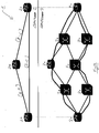
- Fig. 1 shows a multilayer network 1 having a client layer 2 and a corresponding server layer 3.
- the client layer 2 can be a packet switching layer comprising nodes 2A, 2B, 2C formed for example by routers.
- the different nodes 2A, 2B, 2C of the client layer 2 are connected to each other by links. These links can be formed by wireless or by wired links.
- the client layer 2 of the multilayer network 1 comprises three links, i.e.
- first link [A-B] between node 2A and node 2B a first link [A-B] between node 2A and node 2B, a second link [B-C] between the second node 2B and the third node 2C and a third link [A-C] between the first node 2A and the third node 2C of the client layer 2.
- the server layer 3 is provided to serve the client layer 2 and to provide services for the client layer 2.
- Each link of the client layer 2 is served by a connection provisioned in the server layer 3.
- the layers of the multilayer network 1 comprise nodes connected to each other directly via a single link of several parallel links or indirectly via a sequence of links forming a connection between the respective nodes. Accordingly, a sequence of links forms a connection between nodes.
- the server layer 3 can be formed by an optical server layer comprising routers and optical switches. In a further possible implementation this optical server layer can be formed by a wavelength division multiplexing WDM server layer.
- the server layer 3 may be another kind of network comprising electrical wired or wireless links.
- fig. 1 shows the paths ⁇ [a-d, d-b] ⁇ , ⁇ [a-e, e-f, f-h, h-c] ⁇ and ⁇ [b-g, g-c] ⁇ that are configured within the same mutually disjoint link group, MDLG, where they are computed to be mutually disjoint from each other.
- This mutually disjoint link group MDLG can comprise a server layer unique MDLG identifier MDLG-ID.
- the mutually disjoint link group MDLG is a group of links in a given layer that are guaranteed to be mutually network failure independent. This independence is enforced by routing the server layer connections serving the links of the client layer 2 over paths sufficiently disjoint from each other so that it is impossible for a single failure in the server layer 3 to affect more than one connection from the mutually disjoint link group MDLG. For example, if links of a client layer topology are served by server layer connections, the links can be provisioned to be failure independent by forcing the corresponding serving connections of the server layer 3 not to traverse the same links and switching elements in the server layer 3.
- a process of provisioning links that belong to one or more mutually disjoint link groups MDLGs can be described as follows.
- a link can be configured to belong to one or more mutually disjoint link groups MDLGs. This can be accomplished by specifying one or more server layer network unique identifiers MDLG-IDs among the configuration parameters of the respective link.
- a server layer control plane traffic engineering application learns about the appearance of a new link associated with a non-empty list of mutually disjoint link groups MDLGs that can identify other links belonging to each of the mutually disjoint link groups MDLGs.
- Two or more links of the client layer 2 can be configured to belong to the same mutually disjoint link group MDLG.
- Two or more links of the client layer 2 can have link configuration parameters comprising the MDLG identifiers all mutually disjoint link groups MDLGs to which the respective links belong to.
- a path for a connection which serves the new link is calculated to be as disjoint as possible from the path calculated for connections serving existing links within each mutually discount link group MDLG. It is possible that the path selected for the existing links are modified to make them disjoint from the path selected for the connection to serve the new link. The calculated path serving the existing links are modified while keeping them disjoint from each other to make them disjoint from the path calculated for the connection which serves the new link.
- a new link is added to a client layer topology of the client layer 2.
- the new link is added the client layer topology of the client layer 2 in a possible embodiment by advertising the new link via a client layer routing protocol to the nodes of the client layer 2. Accordingly, if the path computation succeeds the new link is added to the client layer topology by advertising the link via the client layer routing protocol.
- the mutually disjoint link groups MDLGs of the link are advertised to the client layer 2 as well. Accordingly, the mutually disjoint link groups MDLGs indicated in the non-empty group list of the new link added to the client layer topology is advertised to the client layer 2.
- the link advertisement of all links of the client layer 2 can be evaluated to discover links having at least one mutually disjoint link group MDLG in common.
- the discovered links are recognized as failure independent links which can be adapted to protect each other against single network failures.
- These kind of network failures can comprise a link failure of a link, a node failure of a node, a configuration error or an application program error.
- a client layer management or control plan can use the information when building various recovery schemes such as MPLS fast reroute FRR looking into the link advertisements to discover links having at least one mutually disjoint link group MDLG in common. Such links cannot be brought down by a single network failure and, hence, can protect each other.
- the client layer 2 and the server layer 3 of the multilayer network 1 are formed by different kind of networks having nodes connected to each other by wired or wireless links.
- the server layer 3 can be formed by an optical network layer such as a wavelength division multiplexing network.
- the server layer 3 can also be formed e.g. by an ATM network or an Ethernet network.
- the nodes of the different network layers can be immobile nodes but also mobile nodes.
- the client layer 2 as shown in fig. 1 can for example form a fragment of a client IP network.
- the nodes 2A, 2B, 2C formed by routers need to be interconnected via the links [A-B], [B-C] and [A-C].
- These links are to be served by connections in the server layer 3 and can be formed for example by an optical layer network.
- the links of the client layer 2 participate in the same protection schemes, i.e. they are provided to protect each other against at least one single network failure.
- the protection schemes of the client layer 2 accordingly, need to be mutually failure independent.
- the protection scheme is provided so that it is impossible for a single network failure to take more than one of the three links of the client layer 2 out of service. This is achieved by routing connections of the server layer 3 serving the client layer links away from each other using a MDLG method as follows.
- a layer connection serving the first client layer link [A-C] is routed.
- the connection is placed for the best available path which can be computed for the server layer 3.
- the computed path is ⁇ [ad]-[df]-[fg]-[gc] ⁇ connecting node 3a and node 3c within the server layer 3.
- nodes 3a, 3b, 3c can be formed by routers and nodes 3d, 3e, 3f, 3g, 3h can be formed by optical switches. Accordingly, the calculated best path connects routers 3a, 3c via optical switches 3d, 3f, 3g. This calculated path in between the two routers 3a, 3c connects the routers indirectly via four links of the server layer 3 to serve the client layer link [A-C] of the client layer 2 as illustrated in fig. 2A .
- step S2 as illustrated in fig. 2B the server layer connection serving the second client layer link [A-B] is routed. Because by this time another client layer link is known to be associated with the mutually disjoint link group MDLGx, i.e. the link [A-C], the server layer connections supporting the two client layer links [A-C, A-B] are rerouted to be disjoint from each other. In the shown example this path computation causes a replacement of the connection serving the first client layer link [A-C] from the path ⁇ [ad]-[df]-[fg]-[gc] ⁇ to a path ⁇ [ae]-[ef]-[fg]-[gc] ⁇ .
- the first router 3a and the third router 3c of the server layer 3 are connected via the optical switches 3e, 3f, 3g.
- the second router 2b is connected to the first router 3a via the optical switch 3d. Therefore, the previously computed path between 3a and 3c is automatically readjusted for the two paths to be mutually disjoint.
- a server layer connection serving the third client layer link [BC] is routed.
- the path computation entity is aware of two other client layer links associated with the mutually disjoint link group MDLGx. Therefore, the path for the third server layer connection has to be disjoint from the previous two calculated paths.
- the path computation leaves the previously calculated path for the connection serving the client layer link [A-B] unchanged but the other path computed for the first server layer connection, i.e.
- connection serving the client layer link [A-C] is modified again from ⁇ [ae]-[ef]-[fg]-[gc] ⁇ to ⁇ [ae]-[ef]-[fh]-[hc] ⁇ . This is done to accommodate the third server layer connection while maintaining all three connections mutually disjoint.
- the method according to the present invention requires in the given example to advertise a single mutually disjoint link group MDLG per link and generally speaking requires only a small number of MDLGs per link to be advertised.
- the method according to the present invention guarantees automatically necessary path disjointness of the server layer 3.
- the calculation can be performed dynamically, e.g. via online path computations by using solely control plane means.
- the calculation can be performed by a centralized or distributed program that has an access to a network traffic engineering data base TED, i.e. a collection of network advertisements.
- One can implement various algorithms for the purpose of path selection and path computation.
- the entity calculating the path can belong to the server layer 3.
- This calculation unit or calculation entity is located in this embodiment on one of the nodes selected by means of the control plane or by a management plane.
- the calculation entity for calculating the path can be located on a stand-alone workstation. If that forms part of a mutually disjoint link group MDLG it can in a possible embodiment be manually configured with the identifier of this group MDLG-ID.
- This attribute along with all other attributes of the respective link can be advertised in a possible implementation into the routing domain via a routing protocol. This means, that every routing protocol speaker of all nodes of the layer gets this information.
- the node or workstation that is charged with the responsibility to compute the path for the MDLG members is a routing protocol speaker, i.e. does participate in the respective routing protocol.
- the MDLG method according to the present invention ensures the existence of network failure independent links via a dynamic concurrent connection or re-routing of connections serving the links forcing the path selection to sufficiently divert each path from all others. Therefore, if it is determined that two or more links have a mutually discount link group MDLG in common it is automatically guaranteed by use of the method according to the present invention that the links are network failure independent. With the method according to the present invention it is permissible to modify one, some or even all paths of connections having links within a given mutually disjoint link group MDLG as long as the paths remain mutually disjoint. Such and path modification allows for the server layer 3 to take advantage of newly added network resources for more optimal paths and address maintenance needs, or network outages to carry out various network policies.
- the method according to the present invention requires only a single or small number of mutually disjoint link groups MDLGs configured and advertised per link. Accordingly, the method of the present invention is much easier to use than compared to conventional methods as far as the client layer 2 is concerned. Therefore, the method according to the present invention is very efficient and can be performed with high speed to protect a multilayer network 1 against network failures.
- the method according to the present invention calculates the network failure independent links with high speed efficiently and automatically so that a safe operation of the multilayer network 1 is guaranteed at all times.
Landscapes
- Engineering & Computer Science (AREA)
- Computer Networks & Wireless Communication (AREA)
- Signal Processing (AREA)
- Data Exchanges In Wide-Area Networks (AREA)
Abstract
Description
- The invention relates to a method for providing network failure independent links in a multilayer network comprising a client layer and a server layer.
- Multilayer networks can comprise at least one client layer and a corresponding server layer which provides services to the client layer. An aspect of traffic engineering of a contemporary transport network is protecting services which the network provides for its users against various network failures such as fiber cuts, device failures, software bugs, configuration errors etc. Such protection is usually achieved in a conventional network via network over-provisioning. The topology of a multilayer network is made up of links and switching elements that can carry user traffic as well as of redundant links that have sufficient unused bandwidth to accommodate the user traffic in case that one or more of the operating or working links go unexpectedly out of service. A major challenge in the context of service protection is the fact that it is never known in advance where the failures are located or occur. Accordingly, working links and the protecting links must be selected to be independent from each other so that it is impossible for a single network failure to bring down both, a working link and the corresponding link protecting the working link.
- Accordingly, there is a need for a method for providing network failure independent links in a multilayer network to provide an operative multilayer network even when working links go out of service.
- The invention provides a method for providing network failure independent links in a multilayer network comprising a client layer and a server layer,
wherein each link of said client layer is served by a connection provisioned in said server layer,
wherein mutually disjoint paths for said connections which serve links in said client layer that belong to the same predetermined mutually disjoint link group MDLG are calculated. - In a possible embodiment of the method according to the present invention each mutually disjoint link group MDLG comprises a server layer unique mutually disjoin link group identifier, MDLG-ID.
- In a possible embodiment of the method according to the present invention two or more links of the client layer are configurable to belong to the same mutually disjoint link group.
- In a further possible embodiment of the method according to the present invention two or more links of the client layer have link configuration parameters comprising the MDLG identifiers of all mutually disjoint link groups to which these links belong.
- In a further possible embodiment of the method according to the present invention the MDLG identifiers of all mutually disjoint link groups to which a link of the client layer belongs to form a group list of mutually disjoint link groups of the respective link.
- In a further possible embodiment of the method according to the present invention if it is detected that a new link associated with a non-empty group list of mutually disjoint link groups is provisioned in said client layer of said multilayer network, other links of said client layer are identified belonging to at least one of the mutually disjoint link groups indicated in the non-empty group list of said new link.
- In a possible embodiment of the method according to the present invention a path for a connection which serves the new link is calculated to be as disjoint as possible from the paths calculated for connections serving existing links within each mutually disjoint link group.
- In a further possible embodiment of the method according to the present invention the calculated paths serving the existing links are modified while keeping them disjoint from each other to make them disjoint from the path calculated for the connection which serves the new link.
- In a possible embodiment of the method according to the present invention if the path successfully calculated for the connection which serves the new link is completely disjoint from the paths serving the existing links of the client layer, the new link is added to a client layer topology of said client layer.
- In a further possible embodiment of the method according to the present invention the new link is added to the client layer topology of said client layer by advertising the new link via a client layer routing protocol to said client layer.
- In a further possible embodiment of the method according to the present invention the mutually disjoint link groups indicated in said non-empty group list of said new link added to the client layer topology are advertised to the client layer.
- In a further possible embodiment of the method according to the present invention the link advertisements of all links of the client layer are evaluated to discover links having at least one mutually disjoint link group in common.
- In a further possible embodiment of the method according to the present invention the discovered links are recognized as failure independent links which can be adapted to protect each other against a single network failure.
- In a further possible embodiment of the method according to the present invention each layer of the multilayer network comprises nodes connected to each other directly via a single link or several parallel links or indirectly via a sequence of links forming a connection between the respective nodes.
- In a further possible embodiment of the method according to the present invention a network failure comprises
a link failure of a link,
a node failure of a node,
a configuration error, and/or
an application program error. - The invention further provides a multilayer network comprising
a client layer and a server layer, each link of said client layer being served by a connection provisioned in said server layer, and
comprising means adapted to calculate mutually disjoint paths for said connections which serve links in said client layer that belong to the same predetermined mutually disjoint link group. - In a possible embodiment of the multilayer network according to the present invention each layer of the multilayer network comprises nodes connected to each other directly via a single link or set of parallel links or indirectly via a sequence of links forming a connection between the respective nodes.
- In a possible embodiment of the multilayer network according to the present invention the client layer is a packet switched client layer comprising routers.
- In a further possible embodiment of the multilayer network according to the present invention the server layer is an optical server layer comprising routers and optical switches.
- In a further possible embodiment of the multilayer network according to the present invention the optical server layer is formed by a wavelength division multiplexing server layer.
- In a further possible embodiment of the multilayer network according to the present invention the links are formed by wireless links.
- In a further possible embodiment of the multilayer network according to the present invention the links are formed by wired links.
- In the following different embodiments of the method for providing network failure independent links in a multilayer network are described with reference to the enclosed figures in more detail.
- Fig. 1
- shows an exemplary multilayer network for which a method for providing network failure independent links according to the present invention can be performed;
- Figs. 2A, 2B, 2C
- illustrate several method steps for providing failure independent links in the exemplary multilayer network of
fig. 1 which are performed by the method for providing network failure independent links according to the present invention. -
Fig. 1 shows a multilayer network 1 having aclient layer 2 and acorresponding server layer 3. In a possible implementation theclient layer 2 can be a packet switchinglayer comprising nodes 2A, 2B, 2C formed for example by routers. Thedifferent nodes 2A, 2B, 2C of theclient layer 2 are connected to each other by links. These links can be formed by wireless or by wired links. In the shown simple exemplary embodiment theclient layer 2 of the multilayer network 1 comprises three links, i.e. a first link [A-B] betweennode 2A and node 2B, a second link [B-C] between the second node 2B and the third node 2C and a third link [A-C] between thefirst node 2A and the third node 2C of theclient layer 2. - As can be seen from
fig. 1 A there is a signal path {[A-B] [B-C]} to be provided to protect signal path{[A-C]}. Accordingly, for example if the link [A-C] between thefirst node 2A and a third node 2C fails there is still a connection between thefirst node 2A and the third node 2C comprising a link [A-B] and a link [B-C] via the second node 2B. In the same manner the path {[A-C][C-B]} is provided to protect link {[A-B]} and the path {[B-A][A-C]} is provided to protect link {[B-C]}. Theserver layer 3 is provided to serve theclient layer 2 and to provide services for theclient layer 2. Each link of theclient layer 2 is served by a connection provisioned in theserver layer 3. The layers of the multilayer network 1 comprise nodes connected to each other directly via a single link of several parallel links or indirectly via a sequence of links forming a connection between the respective nodes. Accordingly, a sequence of links forms a connection between nodes. In a possible implementation theserver layer 3 can be formed by an optical server layer comprising routers and optical switches. In a further possible implementation this optical server layer can be formed by a wavelength division multiplexing WDM server layer. In an alternative embodiment theserver layer 3 may be another kind of network comprising electrical wired or wireless links. To provide network failure independent links between the nodes mutually disjoint paths for the connections which serve links in theclient layer 2 that belong to the same predetermined mutually disjoint link group, MDLG, are calculated. For example,fig. 1 shows the paths {[a-d, d-b]}, {[a-e, e-f, f-h, h-c]} and {[b-g, g-c]} that are configured within the same mutually disjoint link group, MDLG, where they are computed to be mutually disjoint from each other. This mutually disjoint link group MDLG can comprise a server layer unique MDLG identifier MDLG-ID. The mutually disjoint link group MDLG is a group of links in a given layer that are guaranteed to be mutually network failure independent. This independence is enforced by routing the server layer connections serving the links of theclient layer 2 over paths sufficiently disjoint from each other so that it is impossible for a single failure in theserver layer 3 to affect more than one connection from the mutually disjoint link group MDLG. For example, if links of a client layer topology are served by server layer connections, the links can be provisioned to be failure independent by forcing the corresponding serving connections of theserver layer 3 not to traverse the same links and switching elements in theserver layer 3. - A process of provisioning links that belong to one or more mutually disjoint link groups MDLGs can be described as follows. A link can be configured to belong to one or more mutually disjoint link groups MDLGs. This can be accomplished by specifying one or more server layer network unique identifiers MDLG-IDs among the configuration parameters of the respective link. A server layer control plane traffic engineering application learns about the appearance of a new link associated with a non-empty list of mutually disjoint link groups MDLGs that can identify other links belonging to each of the mutually disjoint link groups MDLGs.
- Two or more links of the
client layer 2 can be configured to belong to the same mutually disjoint link group MDLG. Two or more links of theclient layer 2 can have link configuration parameters comprising the MDLG identifiers all mutually disjoint link groups MDLGs to which the respective links belong to. The MDLG identifiers MDLG-IDs of all mutually disjoint link groups MDLG to which a link of theclient layer 2 belongs to form a group list of the mutually disjoint link groups MDLGs of the respective link. If it is detected that a new link associated with a non-empty group list of mutually disjoint link groups MDLGs is provisioned in theclient layer 2 of the multilayer network 1, other links of theclient layer 2 are identified belonging to at least one of the mutually disjoint link groups MDLGs indicated in the non-empty group list of that new link. - A path for a connection which serves the new link is calculated to be as disjoint as possible from the path calculated for connections serving existing links within each mutually discount link group MDLG. It is possible that the path selected for the existing links are modified to make them disjoint from the path selected for the connection to serve the new link. The calculated path serving the existing links are modified while keeping them disjoint from each other to make them disjoint from the path calculated for the connection which serves the new link.
- If the path is successfully calculated for the connection which serves the new link is completely disjoint from the path serving the existing links of the client layer 2 a new link is added to a client layer topology of the
client layer 2. The new link is added the client layer topology of theclient layer 2 in a possible embodiment by advertising the new link via a client layer routing protocol to the nodes of theclient layer 2. Accordingly, if the path computation succeeds the new link is added to the client layer topology by advertising the link via the client layer routing protocol. The mutually disjoint link groups MDLGs of the link are advertised to theclient layer 2 as well. Accordingly, the mutually disjoint link groups MDLGs indicated in the non-empty group list of the new link added to the client layer topology is advertised to theclient layer 2. - The link advertisement of all links of the
client layer 2 can be evaluated to discover links having at least one mutually disjoint link group MDLG in common. The discovered links are recognized as failure independent links which can be adapted to protect each other against single network failures. These kind of network failures can comprise a link failure of a link, a node failure of a node, a configuration error or an application program error. - A client layer management or control plan can use the information when building various recovery schemes such as MPLS fast reroute FRR looking into the link advertisements to discover links having at least one mutually disjoint link group MDLG in common. Such links cannot be brought down by a single network failure and, hence, can protect each other. The
client layer 2 and theserver layer 3 of the multilayer network 1 are formed by different kind of networks having nodes connected to each other by wired or wireless links. For example, theserver layer 3 can be formed by an optical network layer such as a wavelength division multiplexing network. Theserver layer 3 can also be formed e.g. by an ATM network or an Ethernet network. The nodes of the different network layers can be immobile nodes but also mobile nodes. - The
client layer 2 as shown infig. 1 can for example form a fragment of a client IP network. In this exemplary embodiment thenodes 2A, 2B, 2C formed by routers need to be interconnected via the links [A-B], [B-C] and [A-C]. These links are to be served by connections in theserver layer 3 and can be formed for example by an optical layer network. The links of theclient layer 2 participate in the same protection schemes, i.e. they are provided to protect each other against at least one single network failure. The protection schemes of theclient layer 2, accordingly, need to be mutually failure independent. The protection scheme is provided so that it is impossible for a single network failure to take more than one of the three links of theclient layer 2 out of service. This is achieved by routing connections of theserver layer 3 serving the client layer links away from each other using a MDLG method as follows. - In a first step all three links of the
client layer 2 as depicted infig. 1 are configured with the same mutually disjoint link group MDLG, for example MDLGx. In a first step as illustrated in connection withfig. 2A a layer connection serving the first client layer link [A-C] is routed. In the shown example because so far there are no other client layer links configured with MDLGx the connection is placed for the best available path which can be computed for theserver layer 3. In the shown example offig. 2A the computed path is {[ad]-[df]-[fg]-[gc]} connecting node 3a and node 3c within theserver layer 3. In the shown exemplary embodiment nodes 3a, 3b, 3c can be formed by routers andnodes optical switches server layer 3 to serve the client layer link [A-C] of theclient layer 2 as illustrated infig. 2A . - In a further step S2 as illustrated in
fig. 2B the server layer connection serving the second client layer link [A-B] is routed. Because by this time another client layer link is known to be associated with the mutually disjoint link group MDLGx, i.e. the link [A-C], the server layer connections supporting the two client layer links [A-C, A-B] are rerouted to be disjoint from each other. In the shown example this path computation causes a replacement of the connection serving the first client layer link [A-C] from the path {[ad]-[df]-[fg]-[gc]} to a path {[ae]-[ef]-[fg]-[gc]}. It is necessary to make room for routing the second server layer connection sufficiently disjoint from the path computed for the first connection. Accordingly, as can be seen infig. 2B the first router 3a and the third router 3c of theserver layer 3 are connected via theoptical switches 3e, 3f, 3g. The second router 2b is connected to the first router 3a via theoptical switch 3d. Therefore, the previously computed path between 3a and 3c is automatically readjusted for the two paths to be mutually disjoint. - In a further step as illustrated in
fig. 2C a server layer connection serving the third client layer link [BC] is routed. By that time, the path computation entity is aware of two other client layer links associated with the mutually disjoint link group MDLGx. Therefore, the path for the third server layer connection has to be disjoint from the previous two calculated paths. As can be seen in the exemplary server layer this time the path computation leaves the previously calculated path for the connection serving the client layer link [A-B] unchanged but the other path computed for the first server layer connection, i.e. the connection serving the client layer link [A-C] is modified again from {[ae]-[ef]-[fg]-[gc]} to {[ae]-[ef]-[fh]-[hc]}. This is done to accommodate the third server layer connection while maintaining all three connections mutually disjoint. - The method according to the present invention requires in the given example to advertise a single mutually disjoint link group MDLG per link and generally speaking requires only a small number of MDLGs per link to be advertised. The method according to the present invention guarantees automatically necessary path disjointness of the
server layer 3. The calculation can be performed dynamically, e.g. via online path computations by using solely control plane means. The calculation can be performed by a centralized or distributed program that has an access to a network traffic engineering data base TED, i.e. a collection of network advertisements. One can implement various algorithms for the purpose of path selection and path computation. In a possible implementation the entity calculating the path can belong to theserver layer 3. This calculation unit or calculation entity is located in this embodiment on one of the nodes selected by means of the control plane or by a management plane. Alternatively, the calculation entity for calculating the path can be located on a stand-alone workstation. If that forms part of a mutually disjoint link group MDLG it can in a possible embodiment be manually configured with the identifier of this group MDLG-ID. This attribute along with all other attributes of the respective link can be advertised in a possible implementation into the routing domain via a routing protocol. This means, that every routing protocol speaker of all nodes of the layer gets this information. As a consequence, the node or workstation that is charged with the responsibility to compute the path for the MDLG members is a routing protocol speaker, i.e. does participate in the respective routing protocol. The MDLG method according to the present invention ensures the existence of network failure independent links via a dynamic concurrent connection or re-routing of connections serving the links forcing the path selection to sufficiently divert each path from all others. Therefore, if it is determined that two or more links have a mutually discount link group MDLG in common it is automatically guaranteed by use of the method according to the present invention that the links are network failure independent. With the method according to the present invention it is permissible to modify one, some or even all paths of connections having links within a given mutually disjoint link group MDLG as long as the paths remain mutually disjoint. Such and path modification allows for theserver layer 3 to take advantage of newly added network resources for more optimal paths and address maintenance needs, or network outages to carry out various network policies. The method according to the present invention requires only a single or small number of mutually disjoint link groups MDLGs configured and advertised per link. Accordingly, the method of the present invention is much easier to use than compared to conventional methods as far as theclient layer 2 is concerned. Therefore, the method according to the present invention is very efficient and can be performed with high speed to protect a multilayer network 1 against network failures. The method according to the present invention calculates the network failure independent links with high speed efficiently and automatically so that a safe operation of the multilayer network 1 is guaranteed at all times.
Claims (15)
- A method for providing network failure independent links in a multilayer network (1) comprising a client layer (2) and a server layer (3),
wherein each link of said client layer (2) is served by a connection provisioned in said server layer (3), wherein mutually disjoint paths for said connections which serve links in said client layer (2) that belong to the same predetermined mutually disjoint link group, MDLG, are calculated. - The method according to claim 1,
wherein each mutually disjoint link group, MDLG, comprises a server layer unique MDLG identifier. - The method according to claim 1,
wherein two or more links of said client layer (2) are configurable to belong to the same mutually disjoint link group. - The method according to claim 2,
wherein two or more links of said client layer (2) have link configuration parameters comprising the MDLG identifiers of all mutually disjoint link groups to which said links belong. - The method according to claim 4,
wherein the MDLG identifiers of all mutually disjoint link groups to which a link of said client layer (2) belongs do form a group list of mutually disjoint link groups of the respective link. - The method according to claim 1,
wherein, if it is detected that a new link associated with a non-empty group list of mutually disjoint link groups, MDLGs, is provisioned in said client layer (2) of said multilayer network (1), other links of said client layer (2) are identified belonging to at least one of the mutually disjoint link groups, MDLGs, indicated in said non-empty group list of said new link. - The method according to claim 6,
wherein a path for a connection which serves the new link is calculated to be as disjoint as possible from the paths calculated for connections serving existing links within each mutually disjoint link group, MDLG, wherein the calculated paths serving the existing links are modified while keeping them disjoint from each other to make them disjoint from the path calculated for the connection which serves the new link. - The method according to claim 7,
wherein if the path successfully calculated for the connection which serves the new link is completely disjoint from the paths serving the existing links of said client layer (2), the new link is added to a client layer topology of said client layer (2). - The method according to claim 8,
wherein the new link is added to the client layer topology of said client layer (2) by advertising the new link via a client layer routing protocol to said client layer (2),
wherein the mutually disjoint link groups, MDLGs, indicated in said non-empty group list of said new link added to the client layer topology is advertised to said client layer (2). - The method according to claim 9,
wherein the link advertisements of all links of said client layer (2) are evaluated to discover links having at least one mutually disjoint link group, MDLG, in common,
wherein the discovered links are recognized as failure independent links which can be adapted to protect each other against a single network failure. - The method according to claim 1,
wherein each layer (2, 3) of said multilayer network (1) comprises nodes connected to each other directly via a single link or several parallel links or indirectly via a sequence of links forming a connection between the respective nodes. - The method according to claim 1,
wherein a network failure comprises a link failure of a link,
a node failure of a node,
a configuration error, and
an application program error. - A multilayer network (1) comprising a client layer (2) and a server layer (3), each link of said client layer (2) being served by a connection provisioned in said server layer (3), and
comprising means adapted to calculate mutually disjoint paths for said connections serving links in said client layer (2) that belong to the same predetermined mutually disjoint link group, MDLG. - The multilayer network according to claim 13,
wherein each layer of said multilayer network (1) comprises nodes connected to each other directly via a single link or set of parallel links or indirectly via a sequence of links forming a connection between the respective nodes,
wherein said links are formed by wireless or wired links. - The multilayer network according to claim 16,
wherein said client layer (2) is a packet client layer comprising routers and
wherein said server layer (3) is an optical server layer
comprising routers and optical switches,
wherein said optical server layer (8) is a wavelength division multiplexing server layer.
Priority Applications (1)
| Application Number | Priority Date | Filing Date | Title |
|---|---|---|---|
| EP11191524.5A EP2608464B1 (en) | 2011-12-01 | 2011-12-01 | A method for providing network failure independent links in a multilayer network |
Applications Claiming Priority (1)
| Application Number | Priority Date | Filing Date | Title |
|---|---|---|---|
| EP11191524.5A EP2608464B1 (en) | 2011-12-01 | 2011-12-01 | A method for providing network failure independent links in a multilayer network |
Publications (2)
| Publication Number | Publication Date |
|---|---|
| EP2608464A1 true EP2608464A1 (en) | 2013-06-26 |
| EP2608464B1 EP2608464B1 (en) | 2018-02-14 |
Family
ID=45065810
Family Applications (1)
| Application Number | Title | Priority Date | Filing Date |
|---|---|---|---|
| EP11191524.5A Active EP2608464B1 (en) | 2011-12-01 | 2011-12-01 | A method for providing network failure independent links in a multilayer network |
Country Status (1)
| Country | Link |
|---|---|
| EP (1) | EP2608464B1 (en) |
-
2011
- 2011-12-01 EP EP11191524.5A patent/EP2608464B1/en active Active
Non-Patent Citations (1)
| Title |
|---|
| MIYAMURA T ET AL: "A multi-layer disjoint path selection algorithm for highly reliable carrier services", GLOBAL TELECOMMUNICATIONS CONFERENCE, 2004. GLOBECOM '04. IEEE DALLAS, TX, USA 29 NOV.-3 DEC., 2004, PISCATAWAY, NJ, USA,IEEE, PISCATAWAY, NJ, USA, vol. 3, 29 November 2004 (2004-11-29), pages 1974 - 1978, XP010757860, ISBN: 978-0-7803-8794-2, DOI: 10.1109/GLOCOM.2004.1378339 * |
Also Published As
| Publication number | Publication date |
|---|---|
| EP2608464B1 (en) | 2018-02-14 |
Similar Documents
| Publication | Publication Date | Title |
|---|---|---|
| JP5813072B2 (en) | Method and apparatus for providing full logical connectivity in an MPLS network | |
| US10567252B1 (en) | Network connection service high availability evaluation for co-location facilities | |
| US7366109B2 (en) | Virtual private networks within a packet network having a mesh topology | |
| Iannaccone et al. | Feasibility of IP restoration in a tier 1 backbone | |
| US10210058B1 (en) | Application aware inter-chassis redundancy | |
| JP5592385B2 (en) | Provisioned Provider Link State Bridging (PLSB) with routed backup | |
| CN102136940B (en) | Network recovery method and device | |
| US9007916B2 (en) | Network management utilizing topology advertisements | |
| US9722861B2 (en) | Fault-resilient broadcast, multicast, and unicast services | |
| EP3270553B1 (en) | Ospf point-to-multipoint over broadcast or nbma mode | |
| US20120300620A1 (en) | Fast restoration for provider edge node and access link failures | |
| CN104767680B (en) | It route the method and apparatus being switched fast | |
| Schupke | Multilayer and multidomain resilience in optical networks | |
| WO2012100571A1 (en) | Centralized management method and system for multiple tunnels with the same path | |
| CN101155064A (en) | Processing method of traffic engineering link resource information | |
| Puype et al. | Benefits of GMPLS for multilayer recovery | |
| US8761045B2 (en) | Method for providing network failure independent links in a multilayer network | |
| EP2608464B1 (en) | A method for providing network failure independent links in a multilayer network | |
| Xu et al. | Generalized MPLS-based distributed control architecture for automatically switched transport networks | |
| KR20150132767A (en) | Method and apparatus for transmitting data based on point-to-multipoint using sub-gourp on multi-protocol label switching-transport profile network | |
| CN101753521B (en) | Method and device for processing maintenance entity assembly level | |
| Miyazawa et al. | Multi-layer network management system integrated with a network planning tool for IP/optical integrated network | |
| Korniak et al. | Partial redundancy of the control plane routers in the GMPLS controlled optical networks | |
| WO2025049425A1 (en) | Advertising an ip address of loopback interfaces to participating ospf areas | |
| Suzuki et al. | A Network-disaster Recovery System using Area-based Network Management |
Legal Events
| Date | Code | Title | Description |
|---|---|---|---|
| AK | Designated contracting states |
Kind code of ref document: A1 Designated state(s): AL AT BE BG CH CY CZ DE DK EE ES FI FR GB GR HR HU IE IS IT LI LT LU LV MC MK MT NL NO PL PT RO RS SE SI SK SM TR |
|
| AX | Request for extension of the european patent |
Extension state: BA ME |
|
| PUAI | Public reference made under article 153(3) epc to a published international application that has entered the european phase |
Free format text: ORIGINAL CODE: 0009012 |
|
| 17P | Request for examination filed |
Effective date: 20130717 |
|
| RBV | Designated contracting states (corrected) |
Designated state(s): AL AT BE BG CH CY CZ DE DK EE ES FI FR GB GR HR HU IE IS IT LI LT LU LV MC MK MT NL NO PL PT RO RS SE SI SK SM TR |
|
| 17Q | First examination report despatched |
Effective date: 20150331 |
|
| REG | Reference to a national code |
Ref country code: DE Ref legal event code: R079 Ref document number: 602011045597 Country of ref document: DE Free format text: PREVIOUS MAIN CLASS: H04L0012700000 Ipc: H04L0012735000 |
|
| GRAP | Despatch of communication of intention to grant a patent |
Free format text: ORIGINAL CODE: EPIDOSNIGR1 |
|
| STAA | Information on the status of an ep patent application or granted ep patent |
Free format text: STATUS: GRANT OF PATENT IS INTENDED |
|
| RIC1 | Information provided on ipc code assigned before grant |
Ipc: H04L 12/735 20130101AFI20170530BHEP Ipc: H04L 12/703 20130101ALN20170530BHEP Ipc: H04J 14/02 20060101ALI20170530BHEP |
|
| INTG | Intention to grant announced |
Effective date: 20170627 |
|
| GRAS | Grant fee paid |
Free format text: ORIGINAL CODE: EPIDOSNIGR3 |
|
| GRAA | (expected) grant |
Free format text: ORIGINAL CODE: 0009210 |
|
| STAA | Information on the status of an ep patent application or granted ep patent |
Free format text: STATUS: THE PATENT HAS BEEN GRANTED |
|
| AK | Designated contracting states |
Kind code of ref document: B1 Designated state(s): AL AT BE BG CH CY CZ DE DK EE ES FI FR GB GR HR HU IE IS IT LI LT LU LV MC MK MT NL NO PL PT RO RS SE SI SK SM TR |
|
| REG | Reference to a national code |
Ref country code: GB Ref legal event code: FG4D |
|
| REG | Reference to a national code |
Ref country code: CH Ref legal event code: EP |
|
| REG | Reference to a national code |
Ref country code: IE Ref legal event code: FG4D |
|
| REG | Reference to a national code |
Ref country code: DE Ref legal event code: R096 Ref document number: 602011045597 Country of ref document: DE Ref country code: AT Ref legal event code: REF Ref document number: 970549 Country of ref document: AT Kind code of ref document: T Effective date: 20180315 |
|
| REG | Reference to a national code |
Ref country code: NL Ref legal event code: MP Effective date: 20180214 |
|
| REG | Reference to a national code |
Ref country code: AT Ref legal event code: MK05 Ref document number: 970549 Country of ref document: AT Kind code of ref document: T Effective date: 20180214 |
|
| PG25 | Lapsed in a contracting state [announced via postgrant information from national office to epo] |
Ref country code: HR Free format text: LAPSE BECAUSE OF FAILURE TO SUBMIT A TRANSLATION OF THE DESCRIPTION OR TO PAY THE FEE WITHIN THE PRESCRIBED TIME-LIMIT Effective date: 20180214 Ref country code: CY Free format text: LAPSE BECAUSE OF FAILURE TO SUBMIT A TRANSLATION OF THE DESCRIPTION OR TO PAY THE FEE WITHIN THE PRESCRIBED TIME-LIMIT Effective date: 20180214 Ref country code: LT Free format text: LAPSE BECAUSE OF FAILURE TO SUBMIT A TRANSLATION OF THE DESCRIPTION OR TO PAY THE FEE WITHIN THE PRESCRIBED TIME-LIMIT Effective date: 20180214 Ref country code: ES Free format text: LAPSE BECAUSE OF FAILURE TO SUBMIT A TRANSLATION OF THE DESCRIPTION OR TO PAY THE FEE WITHIN THE PRESCRIBED TIME-LIMIT Effective date: 20180214 Ref country code: NL Free format text: LAPSE BECAUSE OF FAILURE TO SUBMIT A TRANSLATION OF THE DESCRIPTION OR TO PAY THE FEE WITHIN THE PRESCRIBED TIME-LIMIT Effective date: 20180214 Ref country code: FI Free format text: LAPSE BECAUSE OF FAILURE TO SUBMIT A TRANSLATION OF THE DESCRIPTION OR TO PAY THE FEE WITHIN THE PRESCRIBED TIME-LIMIT Effective date: 20180214 Ref country code: NO Free format text: LAPSE BECAUSE OF FAILURE TO SUBMIT A TRANSLATION OF THE DESCRIPTION OR TO PAY THE FEE WITHIN THE PRESCRIBED TIME-LIMIT Effective date: 20180514 |
|
| PG25 | Lapsed in a contracting state [announced via postgrant information from national office to epo] |
Ref country code: AT Free format text: LAPSE BECAUSE OF FAILURE TO SUBMIT A TRANSLATION OF THE DESCRIPTION OR TO PAY THE FEE WITHIN THE PRESCRIBED TIME-LIMIT Effective date: 20180214 Ref country code: SE Free format text: LAPSE BECAUSE OF FAILURE TO SUBMIT A TRANSLATION OF THE DESCRIPTION OR TO PAY THE FEE WITHIN THE PRESCRIBED TIME-LIMIT Effective date: 20180214 Ref country code: LV Free format text: LAPSE BECAUSE OF FAILURE TO SUBMIT A TRANSLATION OF THE DESCRIPTION OR TO PAY THE FEE WITHIN THE PRESCRIBED TIME-LIMIT Effective date: 20180214 Ref country code: RS Free format text: LAPSE BECAUSE OF FAILURE TO SUBMIT A TRANSLATION OF THE DESCRIPTION OR TO PAY THE FEE WITHIN THE PRESCRIBED TIME-LIMIT Effective date: 20180214 Ref country code: BG Free format text: LAPSE BECAUSE OF FAILURE TO SUBMIT A TRANSLATION OF THE DESCRIPTION OR TO PAY THE FEE WITHIN THE PRESCRIBED TIME-LIMIT Effective date: 20180514 Ref country code: GR Free format text: LAPSE BECAUSE OF FAILURE TO SUBMIT A TRANSLATION OF THE DESCRIPTION OR TO PAY THE FEE WITHIN THE PRESCRIBED TIME-LIMIT Effective date: 20180515 |
|
| PG25 | Lapsed in a contracting state [announced via postgrant information from national office to epo] |
Ref country code: AL Free format text: LAPSE BECAUSE OF FAILURE TO SUBMIT A TRANSLATION OF THE DESCRIPTION OR TO PAY THE FEE WITHIN THE PRESCRIBED TIME-LIMIT Effective date: 20180214 Ref country code: PL Free format text: LAPSE BECAUSE OF FAILURE TO SUBMIT A TRANSLATION OF THE DESCRIPTION OR TO PAY THE FEE WITHIN THE PRESCRIBED TIME-LIMIT Effective date: 20180214 Ref country code: RO Free format text: LAPSE BECAUSE OF FAILURE TO SUBMIT A TRANSLATION OF THE DESCRIPTION OR TO PAY THE FEE WITHIN THE PRESCRIBED TIME-LIMIT Effective date: 20180214 Ref country code: EE Free format text: LAPSE BECAUSE OF FAILURE TO SUBMIT A TRANSLATION OF THE DESCRIPTION OR TO PAY THE FEE WITHIN THE PRESCRIBED TIME-LIMIT Effective date: 20180214 Ref country code: IT Free format text: LAPSE BECAUSE OF FAILURE TO SUBMIT A TRANSLATION OF THE DESCRIPTION OR TO PAY THE FEE WITHIN THE PRESCRIBED TIME-LIMIT Effective date: 20180214 |
|
| REG | Reference to a national code |
Ref country code: DE Ref legal event code: R097 Ref document number: 602011045597 Country of ref document: DE |
|
| PG25 | Lapsed in a contracting state [announced via postgrant information from national office to epo] |
Ref country code: SK Free format text: LAPSE BECAUSE OF FAILURE TO SUBMIT A TRANSLATION OF THE DESCRIPTION OR TO PAY THE FEE WITHIN THE PRESCRIBED TIME-LIMIT Effective date: 20180214 Ref country code: CZ Free format text: LAPSE BECAUSE OF FAILURE TO SUBMIT A TRANSLATION OF THE DESCRIPTION OR TO PAY THE FEE WITHIN THE PRESCRIBED TIME-LIMIT Effective date: 20180214 Ref country code: DK Free format text: LAPSE BECAUSE OF FAILURE TO SUBMIT A TRANSLATION OF THE DESCRIPTION OR TO PAY THE FEE WITHIN THE PRESCRIBED TIME-LIMIT Effective date: 20180214 Ref country code: SM Free format text: LAPSE BECAUSE OF FAILURE TO SUBMIT A TRANSLATION OF THE DESCRIPTION OR TO PAY THE FEE WITHIN THE PRESCRIBED TIME-LIMIT Effective date: 20180214 |
|
| PLBE | No opposition filed within time limit |
Free format text: ORIGINAL CODE: 0009261 |
|
| STAA | Information on the status of an ep patent application or granted ep patent |
Free format text: STATUS: NO OPPOSITION FILED WITHIN TIME LIMIT |
|
| 26N | No opposition filed |
Effective date: 20181115 |
|
| PG25 | Lapsed in a contracting state [announced via postgrant information from national office to epo] |
Ref country code: SI Free format text: LAPSE BECAUSE OF FAILURE TO SUBMIT A TRANSLATION OF THE DESCRIPTION OR TO PAY THE FEE WITHIN THE PRESCRIBED TIME-LIMIT Effective date: 20180214 |
|
| REG | Reference to a national code |
Ref country code: CH Ref legal event code: PL |
|
| PG25 | Lapsed in a contracting state [announced via postgrant information from national office to epo] |
Ref country code: MC Free format text: LAPSE BECAUSE OF FAILURE TO SUBMIT A TRANSLATION OF THE DESCRIPTION OR TO PAY THE FEE WITHIN THE PRESCRIBED TIME-LIMIT Effective date: 20180214 Ref country code: LU Free format text: LAPSE BECAUSE OF NON-PAYMENT OF DUE FEES Effective date: 20181201 |
|
| REG | Reference to a national code |
Ref country code: IE Ref legal event code: MM4A |
|
| REG | Reference to a national code |
Ref country code: BE Ref legal event code: MM Effective date: 20181231 |
|
| PG25 | Lapsed in a contracting state [announced via postgrant information from national office to epo] |
Ref country code: IE Free format text: LAPSE BECAUSE OF NON-PAYMENT OF DUE FEES Effective date: 20181201 Ref country code: FR Free format text: LAPSE BECAUSE OF NON-PAYMENT OF DUE FEES Effective date: 20181231 |
|
| PG25 | Lapsed in a contracting state [announced via postgrant information from national office to epo] |
Ref country code: BE Free format text: LAPSE BECAUSE OF NON-PAYMENT OF DUE FEES Effective date: 20181231 |
|
| PG25 | Lapsed in a contracting state [announced via postgrant information from national office to epo] |
Ref country code: CH Free format text: LAPSE BECAUSE OF NON-PAYMENT OF DUE FEES Effective date: 20181231 Ref country code: LI Free format text: LAPSE BECAUSE OF NON-PAYMENT OF DUE FEES Effective date: 20181231 |
|
| PG25 | Lapsed in a contracting state [announced via postgrant information from national office to epo] |
Ref country code: MT Free format text: LAPSE BECAUSE OF NON-PAYMENT OF DUE FEES Effective date: 20181201 |
|
| PG25 | Lapsed in a contracting state [announced via postgrant information from national office to epo] |
Ref country code: TR Free format text: LAPSE BECAUSE OF FAILURE TO SUBMIT A TRANSLATION OF THE DESCRIPTION OR TO PAY THE FEE WITHIN THE PRESCRIBED TIME-LIMIT Effective date: 20180214 |
|
| PG25 | Lapsed in a contracting state [announced via postgrant information from national office to epo] |
Ref country code: PT Free format text: LAPSE BECAUSE OF FAILURE TO SUBMIT A TRANSLATION OF THE DESCRIPTION OR TO PAY THE FEE WITHIN THE PRESCRIBED TIME-LIMIT Effective date: 20180214 |
|
| PG25 | Lapsed in a contracting state [announced via postgrant information from national office to epo] |
Ref country code: MK Free format text: LAPSE BECAUSE OF NON-PAYMENT OF DUE FEES Effective date: 20180214 Ref country code: HU Free format text: LAPSE BECAUSE OF FAILURE TO SUBMIT A TRANSLATION OF THE DESCRIPTION OR TO PAY THE FEE WITHIN THE PRESCRIBED TIME-LIMIT; INVALID AB INITIO Effective date: 20111201 |
|
| PG25 | Lapsed in a contracting state [announced via postgrant information from national office to epo] |
Ref country code: IS Free format text: LAPSE BECAUSE OF FAILURE TO SUBMIT A TRANSLATION OF THE DESCRIPTION OR TO PAY THE FEE WITHIN THE PRESCRIBED TIME-LIMIT Effective date: 20180614 |
|
| REG | Reference to a national code |
Ref country code: DE Ref legal event code: R079 Ref document number: 602011045597 Country of ref document: DE Free format text: PREVIOUS MAIN CLASS: H04L0012735000 Ipc: H04L0045128000 |
|
| P01 | Opt-out of the competence of the unified patent court (upc) registered |
Effective date: 20230630 |
|
| REG | Reference to a national code |
Ref country code: DE Ref legal event code: R081 Ref document number: 602011045597 Country of ref document: DE Owner name: ADTRAN NETWORKS SE, DE Free format text: FORMER OWNER: ADVA OPTICAL NETWORKING SE, 82152 PLANEGG, DE |
|
| PGFP | Annual fee paid to national office [announced via postgrant information from national office to epo] |
Ref country code: GB Payment date: 20260122 Year of fee payment: 15 |
|
| PGFP | Annual fee paid to national office [announced via postgrant information from national office to epo] |
Ref country code: DE Payment date: 20251229 Year of fee payment: 15 |