EP2608112A1 - An apparatus for a card holder - Google Patents
An apparatus for a card holder Download PDFInfo
- Publication number
- EP2608112A1 EP2608112A1 EP11194848.5A EP11194848A EP2608112A1 EP 2608112 A1 EP2608112 A1 EP 2608112A1 EP 11194848 A EP11194848 A EP 11194848A EP 2608112 A1 EP2608112 A1 EP 2608112A1
- Authority
- EP
- European Patent Office
- Prior art keywords
- resilient element
- door
- tray
- electronic device
- example embodiment
- Prior art date
- Legal status (The legal status is an assumption and is not a legal conclusion. Google has not performed a legal analysis and makes no representation as to the accuracy of the status listed.)
- Granted
Links
Images





Classifications
-
- H—ELECTRICITY
- H05—ELECTRIC TECHNIQUES NOT OTHERWISE PROVIDED FOR
- H05K—PRINTED CIRCUITS; CASINGS OR CONSTRUCTIONAL DETAILS OF ELECTRIC APPARATUS; MANUFACTURE OF ASSEMBLAGES OF ELECTRICAL COMPONENTS
- H05K7/00—Constructional details common to different types of electric apparatus
- H05K7/14—Mounting supporting structure in casing or on frame or rack
-
- G—PHYSICS
- G06—COMPUTING OR CALCULATING; COUNTING
- G06K—GRAPHICAL DATA READING; PRESENTATION OF DATA; RECORD CARRIERS; HANDLING RECORD CARRIERS
- G06K7/00—Methods or arrangements for sensing record carriers, e.g. for reading patterns
- G06K7/0013—Methods or arrangements for sensing record carriers, e.g. for reading patterns by galvanic contacts, e.g. card connectors for ISO-7816 compliant smart cards or memory cards, e.g. SD card readers
- G06K7/0021—Methods or arrangements for sensing record carriers, e.g. for reading patterns by galvanic contacts, e.g. card connectors for ISO-7816 compliant smart cards or memory cards, e.g. SD card readers for reading/sensing record carriers having surface contacts
-
- G—PHYSICS
- G06—COMPUTING OR CALCULATING; COUNTING
- G06K—GRAPHICAL DATA READING; PRESENTATION OF DATA; RECORD CARRIERS; HANDLING RECORD CARRIERS
- G06K13/00—Conveying record carriers from one station to another, e.g. from stack to punching mechanism
- G06K13/02—Conveying record carriers from one station to another, e.g. from stack to punching mechanism the record carrier having longitudinal dimension comparable with transverse dimension, e.g. punched card
- G06K13/08—Feeding or discharging cards
- G06K13/0806—Feeding or discharging cards using an arrangement for ejection of an inserted card
- G06K13/0831—Feeding or discharging cards using an arrangement for ejection of an inserted card the ejection arrangement comprising a slide, carriage or drawer
-
- H—ELECTRICITY
- H05—ELECTRIC TECHNIQUES NOT OTHERWISE PROVIDED FOR
- H05K—PRINTED CIRCUITS; CASINGS OR CONSTRUCTIONAL DETAILS OF ELECTRIC APPARATUS; MANUFACTURE OF ASSEMBLAGES OF ELECTRICAL COMPONENTS
- H05K7/00—Constructional details common to different types of electric apparatus
- H05K7/14—Mounting supporting structure in casing or on frame or rack
- H05K7/1461—Slidable card holders; Card stiffeners; Control or display means therefor
Definitions
- the present application relates generally to an apparatus for a card holder.
- a card holder may be incorporated into an electronic device into which cards are mounted for inputting and/ or outputting information to the electronic device.
- a card holder comprising:
- FIGURE 1 presents an example embodiment of the invention, in which the card holder is in a first, closed position
- FIGURE 2 presents an example embodiment of the invention, in which the card holder is in a second position
- FIGURE 3 presents an example embodiment of the invention, in which the card holder is in a first, closed position described from above;
- FIGURE 4 presents an example embodiment of the invention, in which the card holder is in a second position described from above;
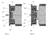
- FIGURE 5 presents an example embodiment of the invention, in which an opening tool is configured to press a resilient element and the resilient element is configured to buckle according to the press.
- FIGURE 6 presents an example embodiment of the invention, in which a door of the card holder is configured to open.
- FIGURE 7 presents an example embodiment of the invention, in which a flange is shown which is coupled to a tray of the card holder.
- FIGURE 8 presents an example embodiment ofthe invention, in which a flange is shown which is configured to pull out the tray when a door is pulled out by a finger.
- FIGURE 9 presents an example embodiment of the invention, in which a card holder is shown in relation with an electronic device cover.
- FIGURE 10 presents an example embodiment of the invention, in which an exploaded view is shown.
- FIGURE 11 presents an example embodiment of the invention, in which an aperture is shown.
- FIGURE 12 presents an example embodiment of the invention, in which an additional component is shown.
- FIGURE 13 presents an example embodiment of the invention, in which a card reader is shown.
- FIGURE 14 presents an example embodiment of the invention, in which a block diagram is shownis shown, describing an electronic device.
- FIGURES 1 through 14 of the drawings An example embodiment of the present invention and its potential advantages are understood by referring to FIGURES 1 through 14 of the drawings.
- FIGURE 1 is an example embodiment of the invention, in which a partial view of an electronic device 100 is shown.
- the partial view shows one of the sides of the electronic device 100, is configured to house a card holder comprising a door 101 and a tray 102 coupled to the door 101.
- the card holder is in a first position.
- FIGURE 2 is an example embodiment of the invention, in which a partial view of an electronic device 100 is shown.
- the partial view shows one of the sides of the electronic device 100, is configured to house a card holder comprising a door 101 and a tray 102 coupled to the door 101.
- the card holder is in a second position.
- FIGURE 3 is an example embodiment of a card holder shown from above according to the example embodiment of FIGURE 1 .
- FIGURE 4 is an example embodiment of a card holder shown from above according to the example embodiment of FIGURE 2 .
- FIGURE 5 is an example embodiment of a card holder in which a resilient element 103 has been shown.
- the resilient element 103 is a resilient element having two ends.
- the resilient element 103 has a relatively flat, elongated shape.
- the resilient element 103 comprises a spring.
- any other shape is possible as well.
- the opening tool 104 is a paper clip which has been folded open in part so as to achieve a self-made tool for opening the card holder.
- any other tool may be used for opening the card holder. It is also possible not to use a specific tool for opening the card holder.
- the user may use for example his/ her finger and or finger nail for opening the card holder.
- the opening tool 104 is configured to be received by an aperture in the door.
- the opening tool 104 is configured to reach the resilient element 103 through the aperture in the door.
- the slots are coinfigured to receive the resilient element 103.
- the resilient element 103 may be attached to the tray 102.
- the cavities 107 and 108 in the shown embodiment have a triangular shape with an apex so that the resilient element 103 is tightly fitted in these cavities 107 and 108, although still allowing a relative movement of the resilient element 103 in the cavities 107 and 108.
- the cavities 107 and 108 are configured to house the resilient element 103 from a longitudinal axis of the resilient element 103.
- the cavities 107 and 108 have a shape of a cut.
- any other shape is possible, for example but not limited to a semi-circular notch.
- the cavities 107 and 108 are configured to enable two pivot points on a longitudinal axis of the resilient element 103.
- the resilient element 103 is configured to move from a first position into a second position around the two pivot points provided by the cavities 107 and 108.
- the first position of the resilient element 103 is configured to follow the first closed position of the card holder.
- the second position of the resilient element 103 is configured to follow the second position ( FIGURES 2 , 4 and 6 ) of the card holder.
- the resilient element 103 has a first, convex shape.
- FIGURE 6 is an example embodiment of a reading device assembly in which due to the pressing movement provided by the opening tool 104, the resilient element 103 is configured to be deflected so that the shape of the resilient element 103 is configured to change.
- the resilient element 103 has a second, concave shape. The difference in the shape of the resilient element 103 has been caused by the deflection resulting from a pressing movement provided by the opening tool 104.
- the tray 102 is not configured to move even though the resilient element 103 is deflected due to an end portion of the tray 102 being arranged against an end wall of the card holder.
- the resilient element 103 when an opening tool 104 is pressing the resilient element 103 from a substantially middle point of the resilient element 103, the resilient element 103 is likely to bend. If the opening tool 104 is not pressing the resilient element 103 enough to provide an opening of the door 101 or closing of the door 101, the resilient element 103 is configured to return to it's original position. As can be seen by contrasting Figure 5 and Figure 6 as the resilient element is deflected between a first position in Figure 5 and a second position in Figure 6 the door 101 moves relative to the tray 102 and as shown in Figures 2 and 4 the door is also moving relative to the elctronic device cover 100.
- the card holder device may act as a stopper element for the end portion of the tray 102 thereby enabling the tray 102 not to move.
- FIGURE 7 is an example embodiment of a card holder in which the resilient element 103 is in a second position and a flange 109 is visible.
- the flange 109 is located on the tray 102 such that when the resilient element 103 is in a second concaveposition, the resilient element 103 is configured to touch the flange 109.
- the flange 109 is a relatively flat component rising from the surface of the tray 102 to meet the resilient element 103 when the resilient element is in the second concave position.
- the flange 109 may have any other shape which enables the flange 109 to contact the resilient element 103.
- the flange 109 may act as a stopper, for preventing the user to push the resilient element 103 too hard.
- the flange 109 may protect the resilient element 103 from being broken if the resilient element 103 is exposed to a significant amount of pressure.
- the flange 109 may act as an ejecting member for the card holder so as to enable the door 101 eject while the flange 109 meets the resilient member 103.
- FIGURE 8 is an example embodiment of the invention according to which the resilient element is in the second position and abuts to the flange 109.
- the resilient element which is coupled to the slots 105, 106 of the tray 102 and the cavities 107, 108 of the door 101 provide coupling between the tray 102 and the door 101 to enable the tray 102 to be pulled out when the user is using for example his/ her finger to pull the outer part of the door 101 thereby opening the door 101 of card holder.
- a flange on the door 109' may couple to the flange 109 on the tray when the resilient element is in the second position. This flange can provide additional or all the coupling between the door and the tray so as to allow the user to pull out the tray 102 when pulling the door 101.
- FIGURE 9 is an example embodiment of the invention according to which the location of the card holder in relation with a cover 1000, 1001, 1002,1003, of the electronic device 100.
- the location of the card holder may be on any of the sides 1000, 1001, 1002 and 1003 of the electronic device 100.
- a printed wire board PWB 1005 is shown.
- the reading device has been integrated on the PWB 1005 and the cover is located on the PWB 1005.
- the card holder is not located on the PWB 1005 and an electrical connection is enabling the reading device to be connected to the PWB 1005.
- FIGURE 10 is an example embodiment of the invention according to which an exploded view is presented where the door 101, resilient element 103, the tray 102 and a card 110 have been shown as separated elements. A reference is made to previous FIGURES 1 - 9 .
- FIGURE 11 is an example embodiment of the invention according to which an aperture 111 is arranged to accommodate an additional component 1007, a depressable element (see Figure 13 ) which may be pressed by for example a fingernail or a coin.
- the outer dimensions of the aperture are different from what has been presented in the example embodiments of FIGURES 1 - 11 to accommodate the additional component 1007.
- FIGURE 12 is an example embodiment of the invention according to which the additional component 1007 is arranged to be attached to the resilient element 103.
- Part 1007 A of the additional component is arranged to protrude from the resilient element 103 towards the tray 102.
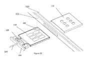
- FIGURE 13 is an example embodiment of the invention according to which a card reader 112 is visible.
- the card reader 112 is configured to house the tray 102 when the tray 102 is in a closed position.
- the card reader 112 according to this example embodiment is an internally installed card reader.
- the card reader 112 is configured to read information from the card so that the user of the electronic device 100 is able to access information stored in the card.
- the card reader 112 is configured to allow data transfer between the electronic device 100 and the card.
- the card reader 112 is configured to save information from the electronic device 100 to the card.
- the card reader 112 is configured to retrieve information from the card to the electronic device 100.
- the shape of the card reader 112 is configured to accommodate and follow the shape of the tray and the card, but any other shape may be possible.
- the card reader may be dimensioned to receive a SIM (subscriber identity module) or a micro SIM or any other suitable card reader for allowing the electorinc device to communicate.
- the card reader 112 may be located on the PWB 1005 near the aperture for inserting and removing the card, in the electronic devices 100 cover.
- FIGURE 14 is an example embodiment of an electronic device 100 according to the invention.
- the electronic device 100 comprises a PWB 1005 configured to support different components of the electronic device 100.
- the electronic device 100 comprises a display 1006 configured to show information to a user of the electronic device 100.
- a display 1006 may provide an output, in input and/or at least part of a user interface.
- the display 1006 may be configured to show information about functionality of the electronic device 100 to a user.
- the display 1006 may be configured to show an application running in the electronic device 100.
- the display 1006 may be for example but not limited to a touch display with resistive or capcitive features or an electronic ink display or a liquid crystal display LCD.
- the electronic device 100 comprises input 1007 configured to provide a user of the electronic device 100 a means of inputting characters and/ or numbers into the electronic device 100.
- the input 1007 may be for example but not limited to a mechanical key or mechanical keys, a joystick, a navigation key, a scroll key or a touch display element.
- the electronic device 100 comprises a power source 1008 configured to provide power to the electronic device 100.
- the power source 1008 may be for example but not limited to a solar cell battery or a li-ion battery.
- the electronic device 100 comprises a transceiver 1009.
- the transceiver of an electronic device 100 may comprise for example an antenna/ transmitter/ receiver 1009, configured to provide connection to a network.
- the transceiver may transmit and receive e.g. radio frequency (RF) signals to/from external network and/or device.
- the network may comprise code devision multiple access ( CDMA ), wideband code devision multiple access ( WCDMA ), 3rd generation ( 3G ), 4th generation ( 4 G ), global system for mobile communications ( GSM ), wireless local area network ( WLAN ) .
- the electronic device 100 may comprise logic/ control/ memory 1010 configured to store, organize and process information.
- the logic /control /memory block 1010 may at least partly control internal data, operations and/or functions of the electronic device 100.
- a processor 1011 is configured to process information.
- the processor 1011 may execute instructions and enable operation of the electronic device 100.
- a speaker 1012 is configured to convert audio signals into sound, and a microphone 1013 is configured to receive for example pressure waves of a sound, and convert the pressure waves into electrical signals.
- the electronic device 100 may be at least one of the following; a mobile/ cellular phone, a lap top computer, an internet tablet, a MP3/ music player, a gaming device, a personal digital assistant. Or any other device having memory and capable of retrieving and saving information on a card.
Landscapes
- Engineering & Computer Science (AREA)
- Physics & Mathematics (AREA)
- General Physics & Mathematics (AREA)
- Theoretical Computer Science (AREA)
- Microelectronics & Electronic Packaging (AREA)
- Artificial Intelligence (AREA)
- Computer Vision & Pattern Recognition (AREA)
- Telephone Set Structure (AREA)
Abstract
and a resilient element wherein the resilient element is configured to move from a first position to a second position upon application of a force on the resilient element, and the door is configured to move relative to the tray upon movement of the resilient element.
Description
- The present application relates generally to an apparatus for a card holder.
- A card holder may be incorporated into an electronic device into which cards are mounted for inputting and/ or outputting information to the electronic device.
- It is known to incorporate a card holder into an electronic device usually at the back side of the electronic device, under a battery. It has become more common to incorporate a card holder into an electronic device at one of the sides of the electronic device, so that in case of an integral battery which is not user changeable, the user can access the card holder and therefore the card.
- Various aspects of examples of the invention are set out in the claims. According to a first aspect of the present invention there is a card holder comprising:
- a tray configured to receive a card,
- a door,
- and a resilient element coupled to the door and the tray,
- wherein the resilient element is configured to move from a first position to a second position upon application of a force on the resilient element, and the door is configured to move relative to the tray upon movement of the resilient element.
- For a more complete understanding of example embodiments of the present invention, reference is now made to the following descriptions taken in connection with the accompanying drawings in which:
-
FIGURE 1 presents an example embodiment of the invention, in which the card holder is in a first, closed position; -
FIGURE 2 presents an example embodiment of the invention, in which the card holder is in a second position; -
FIGURE 3 presents an example embodiment of the invention, in which the card holder is in a first, closed position described from above; -
FIGURE 4 presents an example embodiment of the invention, in which the card holder is in a second position described from above; -
FIGURE 5 presents an example embodiment of the invention, in which an opening tool is configured to press a resilient element and the resilient element is configured to buckle according to the press. -
FIGURE 6 presents an example embodiment of the invention, in which a door of the card holder is configured to open. -
FIGURE 7 presents an example embodiment of the invention, in which a flange is shown which is coupled to a tray of the card holder. -
FIGURE 8 presents an example embodiment ofthe invention, in which a flange is shown which is configured to pull out the tray when a door is pulled out by a finger. -
FIGURE 9 presents an example embodiment of the invention, in which a card holder is shown in relation with an electronic device cover. -
FIGURE 10 presents an example embodiment of the invention, in which an exploaded view is shown. -
FIGURE 11 presents an example embodiment of the invention, in which an aperture is shown. -
FIGURE 12 presents an example embodiment of the invention, in which an additional component is shown. -
FIGURE 13 presents an example embodiment of the invention, in which a card reader is shown. -
FIGURE 14 presents an example embodiment of the invention, in which a block diagram is shownis shown, describing an electronic device. - An example embodiment of the present invention and its potential advantages are understood by referring to
FIGURES 1 through 14 of the drawings. -
FIGURE 1 is an example embodiment of the invention, in which a partial view of anelectronic device 100 is shown. The partial view, shows one of the sides of theelectronic device 100, is configured to house a card holder comprising adoor 101 and atray 102 coupled to thedoor 101. According to this example embodiment, the card holder is in a first position. -
FIGURE 2 is an example embodiment of the invention, in which a partial view of anelectronic device 100 is shown. The partial view, shows one of the sides of theelectronic device 100, is configured to house a card holder comprising adoor 101 and atray 102 coupled to thedoor 101. According to this example embodiment, the card holder is in a second position. -
FIGURE 3 is an example embodiment of a card holder shown from above according to the example embodiment ofFIGURE 1 . -
FIGURE 4 is an example embodiment of a card holder shown from above according to the example embodiment ofFIGURE 2 . -
FIGURE 5 is an example embodiment of a card holder in which aresilient element 103 has been shown. Theresilient element 103 is a resilient element having two ends. According to this example embodiment, theresilient element 103 has a relatively flat, elongated shape. According to another example embodiment, theresilient element 103 comprises a spring. However any other shape is possible as well. For example but not limited to a spiral or a thread. Theresilient element 103 is configured to be pressed by anopening tool 104. According to this example embodiment, theopening tool 104 is a paper clip which has been folded open in part so as to achieve a self-made tool for opening the card holder. However, any other tool may be used for opening the card holder. It is also possible not to use a specific tool for opening the card holder. The user may use for example his/ her finger and or finger nail for opening the card holder. Theopening tool 104 is configured to be received by an aperture in the door. Theopening tool 104 is configured to reach theresilient element 103 through the aperture in the door. There arefirst slots tray 102. The slots are coinfigured to receive theresilient element 103. In an alternative embodiment theresilient element 103 may be attached to thetray 102. There arecavities door 101 and dimensioned to receive the ends of theresilient element 103 . Thecavities resilient element 103 is tightly fitted in thesecavities resilient element 103 in thecavities cavities resilient element 103 from a longitudinal axis of theresilient element 103. According to this example embodiment, thecavities cavities resilient element 103. Theresilient element 103 is configured to move from a first position into a second position around the two pivot points provided by thecavities resilient element 103 is configured to follow the first closed position of the card holder. The second position of theresilient element 103 is configured to follow the second position (FIGURES 2 ,4 and6 ) of the card holder. According to an example embodiment offigure 5 , theresilient element 103 has a first, convex shape. -
FIGURE 6 is an example embodiment of a reading device assembly in which due to the pressing movement provided by theopening tool 104, theresilient element 103 is configured to be deflected so that the shape of theresilient element 103 is configured to change. According to this example embodiment shown infigure 6 , theresilient element 103 has a second, concave shape. The difference in the shape of theresilient element 103 has been caused by the deflection resulting from a pressing movement provided by theopening tool 104. According to this example embodiment, thetray 102 is not configured to move even though theresilient element 103 is deflected due to an end portion of thetray 102 being arranged against an end wall of the card holder. According to this example embodiment, when anopening tool 104 is pressing theresilient element 103 from a substantially middle point of theresilient element 103, theresilient element 103 is likely to bend. If theopening tool 104 is not pressing theresilient element 103 enough to provide an opening of thedoor 101 or closing of thedoor 101, theresilient element 103 is configured to return to it's original position.
As can be seen by contrastingFigure 5 and Figure 6 as the resilient element is deflected between a first position inFigure 5 and a second position inFigure 6 thedoor 101 moves relative to thetray 102 and as shown inFigures 2 and4 the door is also moving relative to theelctronic device cover 100. - According to another example embodiment, there are components within the card holder device, which may act as a stopper element for the end portion of the
tray 102 thereby enabling thetray 102 not to move. -
FIGURE 7 is an example embodiment of a card holder in which theresilient element 103 is in a second position and aflange 109 is visible. Theflange 109 is located on thetray 102 such that when theresilient element 103 is in a second concaveposition, theresilient element 103 is configured to touch theflange 109. According to this example embodiment, theflange 109 is a relatively flat component rising from the surface of thetray 102 to meet theresilient element 103 when the resilient element is in the second concave position. However theflange 109 may have any other shape which enables theflange 109 to contact theresilient element 103. Theflange 109 may act as a stopper, for preventing the user to push theresilient element 103 too hard. Theflange 109 may protect theresilient element 103 from being broken if theresilient element 103 is exposed to a significant amount of pressure. Theflange 109 may act as an ejecting member for the card holder so as to enable thedoor 101 eject while theflange 109 meets theresilient member 103. -
FIGURE 8 is an example embodiment of the invention according to which the resilient element is in the second position and abuts to theflange 109. The resilient element which is coupled to theslots tray 102 and thecavities door 101 provide coupling between thetray 102 and thedoor 101 to enable thetray 102 to be pulled out when the user is using for example his/ her finger to pull the outer part of thedoor 101 thereby opening thedoor 101 of card holder. In addition a flange on the door 109' may couple to theflange 109 on the tray when the resilient element is in the second position. This flange can provide additional or all the coupling between the door and the tray so as to allow the user to pull out thetray 102 when pulling thedoor 101. -
FIGURE 9 is an example embodiment of the invention according to which the location of the card holder in relation with acover electronic device 100. However, the location of the card holder may be on any of thesides electronic device 100. According to this example embodiment, a printedwire board PWB 1005 is shown. The reading device has been integrated on thePWB 1005 and the cover is located on thePWB 1005. According to another embodiment of the invention, the card holder is not located on thePWB 1005 and an electrical connection is enabling the reading device to be connected to thePWB 1005. -
FIGURE 10 is an example embodiment of the invention according to which an exploded view is presented where thedoor 101,resilient element 103, thetray 102 and acard 110 have been shown as separated elements. A reference is made to previousFIGURES 1 - 9 . -
FIGURE 11 is an example embodiment of the invention according to which anaperture 111 is arranged to accommodate anadditional component 1007, a depressable element (seeFigure 13 ) which may be pressed by for example a fingernail or a coin. The outer dimensions of the aperture are different from what has been presented in the example embodiments ofFIGURES 1 - 11 to accommodate theadditional component 1007. -
FIGURE 12 is an example embodiment of the invention according to which theadditional component 1007 is arranged to be attached to theresilient element 103. Part 1007 A of the additional component is arranged to protrude from theresilient element 103 towards thetray 102. -
FIGURE 13 is an example embodiment of the invention according to which acard reader 112 is visible. Thecard reader 112 is configured to house thetray 102 when thetray 102 is in a closed position. Thecard reader 112 according to this example embodiment is an internally installed card reader. Thecard reader 112 is configured to read information from the card so that the user of theelectronic device 100 is able to access information stored in the card. Thecard reader 112 is configured to allow data transfer between theelectronic device 100 and the card. Thecard reader 112 is configured to save information from theelectronic device 100 to the card. Thecard reader 112 is configured to retrieve information from the card to theelectronic device 100. The shape of thecard reader 112 is configured to accommodate and follow the shape of the tray and the card, but any other shape may be possible. The card reader may be dimensioned to receive a SIM (subscriber identity module) or a micro SIM or any other suitable card reader for allowing the electorinc device to communicate. Thecard reader 112 may be located on thePWB 1005 near the aperture for inserting and removing the card, in theelectronic devices 100 cover.FIGURE 14 is an example embodiment of anelectronic device 100 according to the invention. Theelectronic device 100 comprises aPWB 1005 configured to support different components of theelectronic device 100. Theelectronic device 100 comprises adisplay 1006 configured to show information to a user of theelectronic device 100. Adisplay 1006 may provide an output, in input and/or at least part of a user interface. Thedisplay 1006 may be configured to show information about functionality of theelectronic device 100 to a user. Thedisplay 1006 may be configured to show an application running in theelectronic device 100. Thedisplay 1006 may be for example but not limited to a touch display with resistive or capcitive features or an electronic ink display or a liquid crystal display LCD. Theelectronic device 100 comprisesinput 1007 configured to provide a user of the electronic device 100 a means of inputting characters and/ or numbers into theelectronic device 100. Theinput 1007 may be for example but not limited to a mechanical key or mechanical keys, a joystick, a navigation key, a scroll key or a touch display element. Theelectronic device 100 comprises apower source 1008 configured to provide power to theelectronic device 100. Thepower source 1008 may be for example but not limited to a solar cell battery or a li-ion battery. Theelectronic device 100 comprises atransceiver 1009. The transceiver of anelectronic device 100 may comprise for example an antenna/ transmitter/receiver 1009, configured to provide connection to a network. The transceiver may transmit and receive e.g. radio frequency (RF) signals to/from external network and/or device. The network may comprise code devision multiple access ( CDMA ), wideband code devision multiple access ( WCDMA ), 3rd generation ( 3G ), 4th generation ( 4 G ), global system for mobile communications ( GSM ), wireless local area network ( WLAN ) . Theelectronic device 100 may comprise logic/ control/memory 1010 configured to store, organize and process information. The logic /control /memory block 1010 may at least partly control internal data, operations and/or functions of theelectronic device 100. Aprocessor 1011 is configured to process information. Theprocessor 1011 may execute instructions and enable operation of theelectronic device 100. Aspeaker 1012 is configured to convert audio signals into sound, and amicrophone 1013 is configured to receive for example pressure waves of a sound, and convert the pressure waves into electrical signals. - The
electronic device 100 may be at least one of the following; a mobile/ cellular phone, a lap top computer, an internet tablet, a MP3/ music player, a gaming device, a personal digital assistant. Or any other device having memory and capable of retrieving and saving information on a card. - Although various aspects of the invention are set out in the independent claims, other aspects of the invention comprise other combinations of features from the described embodiments and/or the dependent claims with the features of the independent claims, and not solely the combinations explicitly set out in the claims.
- It is also noted herein that while the above describes example embodiments of the invention, these descriptions should not be viewed in a limiting sense. Rather, there are several variations and modifications which may be made without departing from the scope of the present invention as defined in the appended claims.
Claims (17)
- A card holder(101,102) comprising:a tray (102)configured to receive a card,a door (101),and a resilient element (103)coupled to the door (101) and the tray (102),wherein the resilient element is configured to move from a first position to a second position upon application of a force on the resilient element, and the door (101)is configured to move relative to the tray (103) upon movement of the resilient element.
- A apparatus according to claim 1, wherein the resilient element (103)is housed in the card holder and is arranged to pivot about cavities (107,108) located on both sides ofthe door 101).
- An apparatus according to claims 1 and 2, wherein the cavities (107,108) comprise a triangular shape configured to accommodate the ends ofthe resilient element (103).
- An apparatus according to claims 1 - 3, wherein the resilient element (103) is coupled to the tray (102) by way of slots (105,106) in the tray
- An apparatus according to claims 1-3 wherein the resilient element (103) is attached to the tray (102).
- An apparatus according to any preceding claim, wherein the first position of the resilient element corresponds to a first position of the door (101) relative to the tray (102).
- An apparatus according to claims 1 to 5, wherein the second position of the resilient element corresponds to a second position of the door (101) relative to the tray (102).
- An apparatus according to any ofthe preceding claims, wherein the resilient element (103) is configured to be convex in the first position and concave in the second position.
- An apparatus according to any preceding claim wherein the resilient element (103) is any one of a spring, a longitudinal planar member.
- An apparatus according to any preceding claim wherein the tray (102) further comprises a flange(109) and the resilient element(103) abuts the flange (109) in the second position.
- An apparatus according to claim 10 wherein the door (101) comprises a flange (109') and is configured to couple to the flange ofthe tray (109) when the door (101) is pulled in a direction away from the card reader (112).
- An apparatus according to any preceding claim wherein the door (101) comprises an aperture (111) and the resilient element (103) is configured to be deflected by the insertion of a tool (104) placedthrough the aperture.
- An apparatus according to claims 1-11, the apparatus further comprising depressable means (1007, 1007A) coupled to the door (101) and configured to exert a force on the resilient element (103) upon depression of the depressable means.
- An electronic device (100) comprising the apparatus according to any preceding claim.
- An electronic device (100) according to claim 14 wherein when the resilient element (103) is in a second position the tray (102) is configured to be removed from the electronic device (100) by application of a pulling force on the door (101) away from the electronic device (100).
- An electronic device according to claim 14 wherein the door (101) forms part of an outer cover of the electronic device (1000,1001, 1002,1003) when the resilient element (103) is in the first position.
- An apparatus according to claims 14-16, wherein the electronic device (100) comprises at least one of the following; a mobile/ cellular phone, a lap top computer, an internet tablet, a MP3/ music player, a gaming device, a personal digital assistant.
Priority Applications (3)
| Application Number | Priority Date | Filing Date | Title |
|---|---|---|---|
| EP11194848.5A EP2608112B1 (en) | 2011-12-21 | 2011-12-21 | An apparatus for a card holder |
| DE102012112766A DE102012112766A1 (en) | 2011-12-21 | 2012-12-20 | DEVICE FOR A CARD HOLDER |
| US13/723,664 US9456516B2 (en) | 2011-12-21 | 2012-12-21 | Apparatus for a card holder |
Applications Claiming Priority (1)
| Application Number | Priority Date | Filing Date | Title |
|---|---|---|---|
| EP11194848.5A EP2608112B1 (en) | 2011-12-21 | 2011-12-21 | An apparatus for a card holder |
Publications (2)
| Publication Number | Publication Date |
|---|---|
| EP2608112A1 true EP2608112A1 (en) | 2013-06-26 |
| EP2608112B1 EP2608112B1 (en) | 2015-09-09 |
Family
ID=45495664
Family Applications (1)
| Application Number | Title | Priority Date | Filing Date |
|---|---|---|---|
| EP11194848.5A Active EP2608112B1 (en) | 2011-12-21 | 2011-12-21 | An apparatus for a card holder |
Country Status (3)
| Country | Link |
|---|---|
| US (1) | US9456516B2 (en) |
| EP (1) | EP2608112B1 (en) |
| DE (1) | DE102012112766A1 (en) |
Cited By (1)
| Publication number | Priority date | Publication date | Assignee | Title |
|---|---|---|---|---|
| CN104735197A (en) * | 2014-12-26 | 2015-06-24 | 西安易朴通讯技术有限公司 | Mobile terminal card support and mobile terminal |
Families Citing this family (2)
| Publication number | Priority date | Publication date | Assignee | Title |
|---|---|---|---|---|
| CN209562543U (en) * | 2019-01-02 | 2019-10-29 | 东莞富强电子有限公司 | SIM card holder |
| US12124905B1 (en) * | 2021-12-17 | 2024-10-22 | Wells Fargo Bank, N.A. | Transaction instrument with features for destruction and disposal |
Citations (3)
| Publication number | Priority date | Publication date | Assignee | Title |
|---|---|---|---|---|
| DE10339931A1 (en) * | 2003-08-29 | 2005-03-24 | Amphenol-Tuchel Electronics Gmbh | Smart card connector for use in a smart card reading, writing and processing device, has a seal on its front cover that prevents dirt and foreign particle ingress when a card is being read in the drawer of the connector |
| US20080096606A1 (en) * | 2006-10-23 | 2008-04-24 | Samsung Electronics Co. Ltd. | Apparatus for detachably installing a smart card in a portable terminal |
| US20090267677A1 (en) * | 2008-04-25 | 2009-10-29 | Apple Inc. | Compact ejectable component assemblies in electronic devices |
Family Cites Families (7)
| Publication number | Priority date | Publication date | Assignee | Title |
|---|---|---|---|---|
| CN1146083C (en) * | 1997-10-15 | 2004-04-14 | 姚立和 | Memory card box socket |
| TW377898U (en) * | 1998-05-08 | 1999-12-21 | Hon Hai Prec Ind Co Ltd | Improvement for back card mechanism of connector |
| US6088221A (en) * | 1998-06-15 | 2000-07-11 | Compaq Computer Corporation | Hot-pluggable disk drive carrier assembly with no loose parts |
| JP3665235B2 (en) * | 1999-08-31 | 2005-06-29 | 富士通株式会社 | Locking device for computer expansion unit |
| US7594766B1 (en) * | 2002-11-15 | 2009-09-29 | Finisar Corporation | Integrated optical transceiver array |
| US6971914B1 (en) * | 2004-05-12 | 2005-12-06 | Yu-Te Chou | Anti-electromagnetic wave casing for the photoelectric converter |
| CN102427184B (en) * | 2011-08-18 | 2013-12-11 | 鸿富锦精密工业(深圳)有限公司 | Electronic device having ejection mechanism |
-
2011
- 2011-12-21 EP EP11194848.5A patent/EP2608112B1/en active Active
-
2012
- 2012-12-20 DE DE102012112766A patent/DE102012112766A1/en not_active Ceased
- 2012-12-21 US US13/723,664 patent/US9456516B2/en active Active
Patent Citations (3)
| Publication number | Priority date | Publication date | Assignee | Title |
|---|---|---|---|---|
| DE10339931A1 (en) * | 2003-08-29 | 2005-03-24 | Amphenol-Tuchel Electronics Gmbh | Smart card connector for use in a smart card reading, writing and processing device, has a seal on its front cover that prevents dirt and foreign particle ingress when a card is being read in the drawer of the connector |
| US20080096606A1 (en) * | 2006-10-23 | 2008-04-24 | Samsung Electronics Co. Ltd. | Apparatus for detachably installing a smart card in a portable terminal |
| US20090267677A1 (en) * | 2008-04-25 | 2009-10-29 | Apple Inc. | Compact ejectable component assemblies in electronic devices |
Cited By (1)
| Publication number | Priority date | Publication date | Assignee | Title |
|---|---|---|---|---|
| CN104735197A (en) * | 2014-12-26 | 2015-06-24 | 西安易朴通讯技术有限公司 | Mobile terminal card support and mobile terminal |
Also Published As
| Publication number | Publication date |
|---|---|
| US9456516B2 (en) | 2016-09-27 |
| US20130163160A1 (en) | 2013-06-27 |
| DE102012112766A1 (en) | 2013-06-27 |
| EP2608112B1 (en) | 2015-09-09 |
Similar Documents
| Publication | Publication Date | Title |
|---|---|---|
| EP2852008B1 (en) | Card base for sim card and mobile terminal | |
| EP1916776B1 (en) | Apparatus for detachably installing a smart card in a portable terminal | |
| KR101880181B1 (en) | Insert type card retracting/extending apparatus for electronic device | |
| US7306144B2 (en) | Contactless card reader integrated into a touchpad | |
| US7442086B1 (en) | Chip card retaining mechanism | |
| CN103491735A (en) | Back clip of portable electronic device | |
| US8242389B2 (en) | Portable electronic device and method for operating the same | |
| US9837765B2 (en) | Apparatus for ejecting at least one integrated circuit card | |
| US20160240945A1 (en) | Button-type connector module and electronic device using the same | |
| US9456516B2 (en) | Apparatus for a card holder | |
| US7833040B2 (en) | Card socket assembly | |
| US10043114B2 (en) | Electronic device | |
| US20100055948A1 (en) | Card socket assembly | |
| KR100724850B1 (en) | SIM card removal guide device of mobile terminal | |
| US8491320B2 (en) | Portable electronic device with chip card ejecting mechanism | |
| US20110174883A1 (en) | Smart card holding member and portable electronic device employing the same | |
| JP2002279377A (en) | Adapter for plug-in type ic card | |
| EP2034424B1 (en) | Mobile phone and memory card fixing device thereof | |
| JPWO2009031220A1 (en) | Electronics | |
| US20130182399A1 (en) | Surface contact card holder for electronic device | |
| US20100328870A1 (en) | Information processing apparatus | |
| KR100984137B1 (en) | Card type USB device | |
| JP5498298B2 (en) | Base for communication terminal | |
| US9385771B2 (en) | Release mechanism for a smart card | |
| JP5455861B2 (en) | Information equipment terminal |
Legal Events
| Date | Code | Title | Description |
|---|---|---|---|
| AK | Designated contracting states |
Kind code of ref document: A1 Designated state(s): AL AT BE BG CH CY CZ DE DK EE ES FI FR GB GR HR HU IE IS IT LI LT LU LV MC MK MT NL NO PL PT RO RS SE SI SK SM TR |
|
| AX | Request for extension of the european patent |
Extension state: BA ME |
|
| PUAI | Public reference made under article 153(3) epc to a published international application that has entered the european phase |
Free format text: ORIGINAL CODE: 0009012 |
|
| 17P | Request for examination filed |
Effective date: 20131007 |
|
| RBV | Designated contracting states (corrected) |
Designated state(s): AL AT BE BG CH CY CZ DE DK EE ES FI FR GB GR HR HU IE IS IT LI LT LU LV MC MK MT NL NO PL PT RO RS SE SI SK SM TR |
|
| RAP1 | Party data changed (applicant data changed or rights of an application transferred) |
Owner name: NOKIA CORPORATION |
|
| 17Q | First examination report despatched |
Effective date: 20140708 |
|
| GRAP | Despatch of communication of intention to grant a patent |
Free format text: ORIGINAL CODE: EPIDOSNIGR1 |
|
| INTG | Intention to grant announced |
Effective date: 20150420 |
|
| RAP1 | Party data changed (applicant data changed or rights of an application transferred) |
Owner name: NOKIA TECHNOLOGIES OY |
|
| GRAS | Grant fee paid |
Free format text: ORIGINAL CODE: EPIDOSNIGR3 |
|
| GRAA | (expected) grant |
Free format text: ORIGINAL CODE: 0009210 |
|
| AK | Designated contracting states |
Kind code of ref document: B1 Designated state(s): AL AT BE BG CH CY CZ DE DK EE ES FI FR GB GR HR HU IE IS IT LI LT LU LV MC MK MT NL NO PL PT RO RS SE SI SK SM TR |
|
| REG | Reference to a national code |
Ref country code: GB Ref legal event code: FG4D |
|
| REG | Reference to a national code |
Ref country code: AT Ref legal event code: REF Ref document number: 748659 Country of ref document: AT Kind code of ref document: T Effective date: 20150915 Ref country code: CH Ref legal event code: EP |
|
| REG | Reference to a national code |
Ref country code: IE Ref legal event code: FG4D |
|
| REG | Reference to a national code |
Ref country code: DE Ref legal event code: R096 Ref document number: 602011019550 Country of ref document: DE |
|
| REG | Reference to a national code |
Ref country code: NL Ref legal event code: MP Effective date: 20150909 |
|
| PG25 | Lapsed in a contracting state [announced via postgrant information from national office to epo] |
Ref country code: FI Free format text: LAPSE BECAUSE OF FAILURE TO SUBMIT A TRANSLATION OF THE DESCRIPTION OR TO PAY THE FEE WITHIN THE PRESCRIBED TIME-LIMIT Effective date: 20150909 Ref country code: GR Free format text: LAPSE BECAUSE OF FAILURE TO SUBMIT A TRANSLATION OF THE DESCRIPTION OR TO PAY THE FEE WITHIN THE PRESCRIBED TIME-LIMIT Effective date: 20151210 Ref country code: LT Free format text: LAPSE BECAUSE OF FAILURE TO SUBMIT A TRANSLATION OF THE DESCRIPTION OR TO PAY THE FEE WITHIN THE PRESCRIBED TIME-LIMIT Effective date: 20150909 Ref country code: NO Free format text: LAPSE BECAUSE OF FAILURE TO SUBMIT A TRANSLATION OF THE DESCRIPTION OR TO PAY THE FEE WITHIN THE PRESCRIBED TIME-LIMIT Effective date: 20151209 Ref country code: LV Free format text: LAPSE BECAUSE OF FAILURE TO SUBMIT A TRANSLATION OF THE DESCRIPTION OR TO PAY THE FEE WITHIN THE PRESCRIBED TIME-LIMIT Effective date: 20150909 |
|
| REG | Reference to a national code |
Ref country code: LT Ref legal event code: MG4D |
|
| REG | Reference to a national code |
Ref country code: AT Ref legal event code: MK05 Ref document number: 748659 Country of ref document: AT Kind code of ref document: T Effective date: 20150909 |
|
| PG25 | Lapsed in a contracting state [announced via postgrant information from national office to epo] |
Ref country code: ES Free format text: LAPSE BECAUSE OF FAILURE TO SUBMIT A TRANSLATION OF THE DESCRIPTION OR TO PAY THE FEE WITHIN THE PRESCRIBED TIME-LIMIT Effective date: 20150909 Ref country code: HR Free format text: LAPSE BECAUSE OF FAILURE TO SUBMIT A TRANSLATION OF THE DESCRIPTION OR TO PAY THE FEE WITHIN THE PRESCRIBED TIME-LIMIT Effective date: 20150909 Ref country code: RS Free format text: LAPSE BECAUSE OF FAILURE TO SUBMIT A TRANSLATION OF THE DESCRIPTION OR TO PAY THE FEE WITHIN THE PRESCRIBED TIME-LIMIT Effective date: 20150909 Ref country code: SE Free format text: LAPSE BECAUSE OF FAILURE TO SUBMIT A TRANSLATION OF THE DESCRIPTION OR TO PAY THE FEE WITHIN THE PRESCRIBED TIME-LIMIT Effective date: 20150909 |
|
| PG25 | Lapsed in a contracting state [announced via postgrant information from national office to epo] |
Ref country code: NL Free format text: LAPSE BECAUSE OF FAILURE TO SUBMIT A TRANSLATION OF THE DESCRIPTION OR TO PAY THE FEE WITHIN THE PRESCRIBED TIME-LIMIT Effective date: 20150909 |
|
| PG25 | Lapsed in a contracting state [announced via postgrant information from national office to epo] |
Ref country code: IS Free format text: LAPSE BECAUSE OF FAILURE TO SUBMIT A TRANSLATION OF THE DESCRIPTION OR TO PAY THE FEE WITHIN THE PRESCRIBED TIME-LIMIT Effective date: 20160109 Ref country code: IT Free format text: LAPSE BECAUSE OF FAILURE TO SUBMIT A TRANSLATION OF THE DESCRIPTION OR TO PAY THE FEE WITHIN THE PRESCRIBED TIME-LIMIT Effective date: 20150909 Ref country code: SK Free format text: LAPSE BECAUSE OF FAILURE TO SUBMIT A TRANSLATION OF THE DESCRIPTION OR TO PAY THE FEE WITHIN THE PRESCRIBED TIME-LIMIT Effective date: 20150909 Ref country code: EE Free format text: LAPSE BECAUSE OF FAILURE TO SUBMIT A TRANSLATION OF THE DESCRIPTION OR TO PAY THE FEE WITHIN THE PRESCRIBED TIME-LIMIT Effective date: 20150909 Ref country code: CZ Free format text: LAPSE BECAUSE OF FAILURE TO SUBMIT A TRANSLATION OF THE DESCRIPTION OR TO PAY THE FEE WITHIN THE PRESCRIBED TIME-LIMIT Effective date: 20150909 |
|
| PG25 | Lapsed in a contracting state [announced via postgrant information from national office to epo] |
Ref country code: BE Free format text: LAPSE BECAUSE OF NON-PAYMENT OF DUE FEES Effective date: 20151231 Ref country code: AT Free format text: LAPSE BECAUSE OF FAILURE TO SUBMIT A TRANSLATION OF THE DESCRIPTION OR TO PAY THE FEE WITHIN THE PRESCRIBED TIME-LIMIT Effective date: 20150909 Ref country code: PL Free format text: LAPSE BECAUSE OF FAILURE TO SUBMIT A TRANSLATION OF THE DESCRIPTION OR TO PAY THE FEE WITHIN THE PRESCRIBED TIME-LIMIT Effective date: 20150909 Ref country code: PT Free format text: LAPSE BECAUSE OF FAILURE TO SUBMIT A TRANSLATION OF THE DESCRIPTION OR TO PAY THE FEE WITHIN THE PRESCRIBED TIME-LIMIT Effective date: 20160111 Ref country code: RO Free format text: LAPSE BECAUSE OF FAILURE TO SUBMIT A TRANSLATION OF THE DESCRIPTION OR TO PAY THE FEE WITHIN THE PRESCRIBED TIME-LIMIT Effective date: 20150909 |
|
| REG | Reference to a national code |
Ref country code: DE Ref legal event code: R097 Ref document number: 602011019550 Country of ref document: DE |
|
| REG | Reference to a national code |
Ref country code: DE Ref legal event code: R119 Ref document number: 602011019550 Country of ref document: DE |
|
| PLBE | No opposition filed within time limit |
Free format text: ORIGINAL CODE: 0009261 |
|
| STAA | Information on the status of an ep patent application or granted ep patent |
Free format text: STATUS: NO OPPOSITION FILED WITHIN TIME LIMIT |
|
| PG25 | Lapsed in a contracting state [announced via postgrant information from national office to epo] |
Ref country code: LU Free format text: LAPSE BECAUSE OF FAILURE TO SUBMIT A TRANSLATION OF THE DESCRIPTION OR TO PAY THE FEE WITHIN THE PRESCRIBED TIME-LIMIT Effective date: 20151221 Ref country code: MC Free format text: LAPSE BECAUSE OF FAILURE TO SUBMIT A TRANSLATION OF THE DESCRIPTION OR TO PAY THE FEE WITHIN THE PRESCRIBED TIME-LIMIT Effective date: 20150909 |
|
| REG | Reference to a national code |
Ref country code: CH Ref legal event code: PL |
|
| 26N | No opposition filed |
Effective date: 20160610 |
|
| PG25 | Lapsed in a contracting state [announced via postgrant information from national office to epo] |
Ref country code: DK Free format text: LAPSE BECAUSE OF FAILURE TO SUBMIT A TRANSLATION OF THE DESCRIPTION OR TO PAY THE FEE WITHIN THE PRESCRIBED TIME-LIMIT Effective date: 20150909 Ref country code: SI Free format text: LAPSE BECAUSE OF FAILURE TO SUBMIT A TRANSLATION OF THE DESCRIPTION OR TO PAY THE FEE WITHIN THE PRESCRIBED TIME-LIMIT Effective date: 20150909 |
|
| REG | Reference to a national code |
Ref country code: IE Ref legal event code: MM4A |
|
| REG | Reference to a national code |
Ref country code: FR Ref legal event code: ST Effective date: 20160831 |
|
| PG25 | Lapsed in a contracting state [announced via postgrant information from national office to epo] |
Ref country code: IE Free format text: LAPSE BECAUSE OF NON-PAYMENT OF DUE FEES Effective date: 20151221 Ref country code: CH Free format text: LAPSE BECAUSE OF NON-PAYMENT OF DUE FEES Effective date: 20151231 Ref country code: LI Free format text: LAPSE BECAUSE OF NON-PAYMENT OF DUE FEES Effective date: 20151231 Ref country code: DE Free format text: LAPSE BECAUSE OF NON-PAYMENT OF DUE FEES Effective date: 20160701 |
|
| PG25 | Lapsed in a contracting state [announced via postgrant information from national office to epo] |
Ref country code: FR Free format text: LAPSE BECAUSE OF NON-PAYMENT OF DUE FEES Effective date: 20151231 |
|
| PG25 | Lapsed in a contracting state [announced via postgrant information from national office to epo] |
Ref country code: BE Free format text: LAPSE BECAUSE OF FAILURE TO SUBMIT A TRANSLATION OF THE DESCRIPTION OR TO PAY THE FEE WITHIN THE PRESCRIBED TIME-LIMIT Effective date: 20150909 |
|
| PG25 | Lapsed in a contracting state [announced via postgrant information from national office to epo] |
Ref country code: BG Free format text: LAPSE BECAUSE OF FAILURE TO SUBMIT A TRANSLATION OF THE DESCRIPTION OR TO PAY THE FEE WITHIN THE PRESCRIBED TIME-LIMIT Effective date: 20150909 Ref country code: SM Free format text: LAPSE BECAUSE OF FAILURE TO SUBMIT A TRANSLATION OF THE DESCRIPTION OR TO PAY THE FEE WITHIN THE PRESCRIBED TIME-LIMIT Effective date: 20150909 Ref country code: HU Free format text: LAPSE BECAUSE OF FAILURE TO SUBMIT A TRANSLATION OF THE DESCRIPTION OR TO PAY THE FEE WITHIN THE PRESCRIBED TIME-LIMIT; INVALID AB INITIO Effective date: 20111221 |
|
| PG25 | Lapsed in a contracting state [announced via postgrant information from national office to epo] |
Ref country code: CY Free format text: LAPSE BECAUSE OF FAILURE TO SUBMIT A TRANSLATION OF THE DESCRIPTION OR TO PAY THE FEE WITHIN THE PRESCRIBED TIME-LIMIT Effective date: 20150909 |
|
| PG25 | Lapsed in a contracting state [announced via postgrant information from national office to epo] |
Ref country code: MT Free format text: LAPSE BECAUSE OF FAILURE TO SUBMIT A TRANSLATION OF THE DESCRIPTION OR TO PAY THE FEE WITHIN THE PRESCRIBED TIME-LIMIT Effective date: 20150909 |
|
| PG25 | Lapsed in a contracting state [announced via postgrant information from national office to epo] |
Ref country code: TR Free format text: LAPSE BECAUSE OF FAILURE TO SUBMIT A TRANSLATION OF THE DESCRIPTION OR TO PAY THE FEE WITHIN THE PRESCRIBED TIME-LIMIT Effective date: 20150909 Ref country code: MK Free format text: LAPSE BECAUSE OF FAILURE TO SUBMIT A TRANSLATION OF THE DESCRIPTION OR TO PAY THE FEE WITHIN THE PRESCRIBED TIME-LIMIT Effective date: 20150909 |
|
| PG25 | Lapsed in a contracting state [announced via postgrant information from national office to epo] |
Ref country code: AL Free format text: LAPSE BECAUSE OF FAILURE TO SUBMIT A TRANSLATION OF THE DESCRIPTION OR TO PAY THE FEE WITHIN THE PRESCRIBED TIME-LIMIT Effective date: 20150909 |
|
| P01 | Opt-out of the competence of the unified patent court (upc) registered |
Effective date: 20230527 |
|
| PGFP | Annual fee paid to national office [announced via postgrant information from national office to epo] |
Ref country code: GB Payment date: 20251030 Year of fee payment: 15 |