EP2608003A1 - Method and device for movement of image object - Google Patents
Method and device for movement of image object Download PDFInfo
- Publication number
- EP2608003A1 EP2608003A1 EP11817755.9A EP11817755A EP2608003A1 EP 2608003 A1 EP2608003 A1 EP 2608003A1 EP 11817755 A EP11817755 A EP 11817755A EP 2608003 A1 EP2608003 A1 EP 2608003A1
- Authority
- EP
- European Patent Office
- Prior art keywords
- module
- smallest
- movement
- area
- unit
- Prior art date
- Legal status (The legal status is an assumption and is not a legal conclusion. Google has not performed a legal analysis and makes no representation as to the accuracy of the status listed.)
- Granted
Links
Images



Classifications
-
- G—PHYSICS
- G06—COMPUTING OR CALCULATING; COUNTING
- G06F—ELECTRIC DIGITAL DATA PROCESSING
- G06F3/00—Input arrangements for transferring data to be processed into a form capable of being handled by the computer; Output arrangements for transferring data from processing unit to output unit, e.g. interface arrangements
- G06F3/01—Input arrangements or combined input and output arrangements for interaction between user and computer
- G06F3/048—Interaction techniques based on graphical user interfaces [GUI]
- G06F3/0481—Interaction techniques based on graphical user interfaces [GUI] based on specific properties of the displayed interaction object or a metaphor-based environment, e.g. interaction with desktop elements like windows or icons, or assisted by a cursor's changing behaviour or appearance
- G06F3/04812—Interaction techniques based on cursor appearance or behaviour, e.g. being affected by the presence of displayed objects
-
- G—PHYSICS
- G06—COMPUTING OR CALCULATING; COUNTING
- G06F—ELECTRIC DIGITAL DATA PROCESSING
- G06F3/00—Input arrangements for transferring data to be processed into a form capable of being handled by the computer; Output arrangements for transferring data from processing unit to output unit, e.g. interface arrangements
- G06F3/14—Digital output to display device ; Cooperation and interconnection of the display device with other functional units
-
- G—PHYSICS
- G06—COMPUTING OR CALCULATING; COUNTING
- G06F—ELECTRIC DIGITAL DATA PROCESSING
- G06F3/00—Input arrangements for transferring data to be processed into a form capable of being handled by the computer; Output arrangements for transferring data from processing unit to output unit, e.g. interface arrangements
- G06F3/01—Input arrangements or combined input and output arrangements for interaction between user and computer
- G06F3/048—Interaction techniques based on graphical user interfaces [GUI]
- G06F3/0481—Interaction techniques based on graphical user interfaces [GUI] based on specific properties of the displayed interaction object or a metaphor-based environment, e.g. interaction with desktop elements like windows or icons, or assisted by a cursor's changing behaviour or appearance
-
- G—PHYSICS
- G06—COMPUTING OR CALCULATING; COUNTING
- G06F—ELECTRIC DIGITAL DATA PROCESSING
- G06F3/00—Input arrangements for transferring data to be processed into a form capable of being handled by the computer; Output arrangements for transferring data from processing unit to output unit, e.g. interface arrangements
- G06F3/01—Input arrangements or combined input and output arrangements for interaction between user and computer
- G06F3/048—Interaction techniques based on graphical user interfaces [GUI]
-
- G—PHYSICS
- G06—COMPUTING OR CALCULATING; COUNTING
- G06F—ELECTRIC DIGITAL DATA PROCESSING
- G06F3/00—Input arrangements for transferring data to be processed into a form capable of being handled by the computer; Output arrangements for transferring data from processing unit to output unit, e.g. interface arrangements
- G06F3/01—Input arrangements or combined input and output arrangements for interaction between user and computer
- G06F3/048—Interaction techniques based on graphical user interfaces [GUI]
- G06F3/0484—Interaction techniques based on graphical user interfaces [GUI] for the control of specific functions or operations, e.g. selecting or manipulating an object, an image or a displayed text element, setting a parameter value or selecting a range
-
- G—PHYSICS
- G06—COMPUTING OR CALCULATING; COUNTING
- G06F—ELECTRIC DIGITAL DATA PROCESSING
- G06F3/00—Input arrangements for transferring data to be processed into a form capable of being handled by the computer; Output arrangements for transferring data from processing unit to output unit, e.g. interface arrangements
- G06F3/01—Input arrangements or combined input and output arrangements for interaction between user and computer
- G06F3/048—Interaction techniques based on graphical user interfaces [GUI]
- G06F3/0484—Interaction techniques based on graphical user interfaces [GUI] for the control of specific functions or operations, e.g. selecting or manipulating an object, an image or a displayed text element, setting a parameter value or selecting a range
- G06F3/04842—Selection of displayed objects or displayed text elements
-
- G—PHYSICS
- G06—COMPUTING OR CALCULATING; COUNTING
- G06F—ELECTRIC DIGITAL DATA PROCESSING
- G06F3/00—Input arrangements for transferring data to be processed into a form capable of being handled by the computer; Output arrangements for transferring data from processing unit to output unit, e.g. interface arrangements
- G06F3/01—Input arrangements or combined input and output arrangements for interaction between user and computer
- G06F3/048—Interaction techniques based on graphical user interfaces [GUI]
- G06F3/0484—Interaction techniques based on graphical user interfaces [GUI] for the control of specific functions or operations, e.g. selecting or manipulating an object, an image or a displayed text element, setting a parameter value or selecting a range
- G06F3/04845—Interaction techniques based on graphical user interfaces [GUI] for the control of specific functions or operations, e.g. selecting or manipulating an object, an image or a displayed text element, setting a parameter value or selecting a range for image manipulation, e.g. dragging, rotation, expansion or change of colour
-
- G—PHYSICS
- G06—COMPUTING OR CALCULATING; COUNTING
- G06F—ELECTRIC DIGITAL DATA PROCESSING
- G06F3/00—Input arrangements for transferring data to be processed into a form capable of being handled by the computer; Output arrangements for transferring data from processing unit to output unit, e.g. interface arrangements
- G06F3/01—Input arrangements or combined input and output arrangements for interaction between user and computer
- G06F3/048—Interaction techniques based on graphical user interfaces [GUI]
- G06F3/0487—Interaction techniques based on graphical user interfaces [GUI] using specific features provided by the input device, e.g. functions controlled by the rotation of a mouse with dual sensing arrangements, or of the nature of the input device, e.g. tap gestures based on pressure sensed by a digitiser
- G06F3/0488—Interaction techniques based on graphical user interfaces [GUI] using specific features provided by the input device, e.g. functions controlled by the rotation of a mouse with dual sensing arrangements, or of the nature of the input device, e.g. tap gestures based on pressure sensed by a digitiser using a touch-screen or digitiser, e.g. input of commands through traced gestures
- G06F3/04883—Interaction techniques based on graphical user interfaces [GUI] using specific features provided by the input device, e.g. functions controlled by the rotation of a mouse with dual sensing arrangements, or of the nature of the input device, e.g. tap gestures based on pressure sensed by a digitiser using a touch-screen or digitiser, e.g. input of commands through traced gestures for inputting data by handwriting, e.g. gesture or text
Definitions
- the present invention relates to a mobile terminal technology and particularly to a method and apparatus for moving a graphic object.
- a smart mobile phone and other mobile terminals are typically provided with a display screen, of a specific size, corresponding to an area referred to as a display area, typically a rectangle, on which graphic objects corresponding to various applications, pictures, videos, etc., can be displayed, and a user can access a function corresponding to a graphic object (which can be an icon, a widget, a pure picture, etc.) by clicking on the graphic object.
- a graphic object which can be an icon, a widget, a pure picture, etc.
- the existing smart mobile phone and other mobile terminals may allow the user to drag the various graphic objects as needed, that is, to change the locations of the graphic objects, thus encouraging an access of the user.
- a general object of the invention is to provide a method for moving a graphic obj ect so as to improve a success ratio of moving a graphic obj ect.
- Another object of the invention is to provide an apparatus for moving a graphic object so as to improve an experience of a user.
- a method of moving a graphic object includes:
- An apparatus for moving a graphic object includes:
- a module X corresponding to a graphic obj ect to be moved is moved in a movement direction, and if there is no overlapping part with any other module, then the status after the movement is taken as a movement result; otherwise, the modules are swapped in location, thereby avoiding overlapping of different graphic objects and improving a success ratio of moving a graphic object.
- the solution of the invention is highly extensible and can be applicable to mobile terminals with differently sized display areas.
- the solution of the invention is easy to implement and reliable to operate and will not be restricted by an operating system platform, a programming language, etc., and thus is convenient to spread.
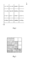
- Fig.1 is a flow chart of an embodiment of a method for moving a graphic object according to the invention
- Fig.2 is a schematic diagram of a mask table in the embodiment of the method according to the invention.
- Fig.3 is a schematic diagram of a display area in the embodiment of the method according to the invention.
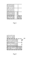
- Fig.4 is a schematic diagram after a module corresponding to a graphic object to be moved is moved by one unit in a movement direction in the embodiment of the method according to the invention
- Fig.5 is a schematic diagram of a smallest envelope rectangular area A1 determined in the embodiment of the method according to the invention.
- Fig.6 is a schematic diagram of a smallest envelope rectangular area A2 determined in the embodiment of the method according to the invention.
- Fig.7 is a schematic diagram of an inverted smallest mirrored area in the embodiment of the method according to the invention.
- Fig.8 is a schematic constituent structural diagram of an embodiment of an apparatus for moving a graphic object according to the invention.
- a new solution of moving a graphic object so as to avoid overlapping of different graphic objects to thereby improve an experience of a user.
- the graphic object includes but will not be limited to an icon, a widget, a pure picture, etc.
- Fig.1 is a flow chart of an embodiment of a method for moving a graphic object according to the invention. As illustrated in Fig. 1 , the method includes the following steps:
- the step 11 is to determine a module X and a movement direction corresponding to a graphic obj ect to be moved.
- Each graphic object may occupy an area with a specific size (with a length and a width smaller than or equal to the length and the width of the display area), and in this embodiment, an area corresponding to the graphic object to be moved is referred to be as a module X.
- the module X and the movement direction corresponding to the graphic object to be moved can be determined by monitoring an operation of a user. For example, the user selects a graphic object 1 through a cursor and clicks on a Down key, and then the area corresponding to the graphic object 1 is determined as the module X, and the downward direction is determined as the movement direction.
- the user selects a graphic object 1 through a cursor and clicks on a Down key, and then the area corresponding to the graphic object 1 is determined as the module X, and the downward direction is determined as the movement direction.
- this is merely exemplary, and the invention will not be limited thereto.
- the step 12 is to move the module X by one unit in the movement direction.
- the step 13 is to determine whether the module X overlaps partially with another module, and if not so, then the process goes to the step 14; otherwise, the process goes to the step 15.
- a two-dimension struct array referred to as a mask table can be maintained for the display area.
- Fig.2 is a schematic diagram of the mask table in the embodiment of the method according to the invention. As illustrated in Fig.2 , the size of the display area is assumed as 4 ⁇ 4, and each element in the mask table records two pieces of contents, one of which indicates whether a grid corresponding thereto is occupied, where if the grid is occupied, then the indicator is 1; otherwise, the indicator is 0; and the other of which indicates a memory address of a module occupying the grid (a memory address of each module is unique), where the memory address is Null when the grid is not occupied. As can be apparent from Fig.2 , four grids are occupied, and a memory address of the module occupying the four grids is 0x100.
- the step 14 is to take the status after the movement as a movement result, and the flow ends.
- the step 15 is to restore the module X to its original location and to determine and mirror-invert a smallest mirrored area including the module X.
- a module overlapping partially with the module X moved by one unit in the movement direction in the step 13 can be defined as an obstructive module, and then this step can be performed particularly as follows:
- a smallest envelope rectangular area A2 including the entire area of the module partially located in the smallest envelope rectangular area A1, the module X and the obstructive module is further determined as the smallest mirrored area.
- the smallest mirrored area is mirror-inverted by taking as an axis a line connecting midpoints of two sides of the smallest mirrored area, which are parallel to the movement direction of the module X, and a specific inversion approach falls into the prior art and thus a repeated description thereof will be omitted here.
- Fig.3 is a schematic diagram of the display area in the embodiment of the method according to the invention. As illustrated in Fig.3 , the size of the display area is assumed as 4 ⁇ 4, which includes 4 modules in total, i.e., a module 1, a module 2, a module 3 and a module 4 respectively, with the module 2 being the module corresponding to the graphic object to be moved.
- Fig.4 is a schematic diagram after the module corresponding to the graphic object to be moved is moved by one unit (i.e., one grid) in the movement direction in the embodiment of the method according to the invention.
- the moved module 2 overlaps partially with the module 4, and then the module 4 is an obstructive module (the number of obstructive modules may be more than one in a practical application although there is only one here as an example).
- Fig.5 is a schematic diagram of the smallest envelope rectangular area A1 determined in the embodiment of the method according to the invention. As illustrated in Fig.5 , the smallest envelope rectangular area A1 includes the entire area of the module 2 and the module 4 and also includes the entire area of the module 3 and a part of the area of the module 1, so the smallest envelope rectangular area A1 can not be taken as a smallest mirrored area.
- Fig.6 is a schematic diagram of the smallest envelope rectangular area A2 determined in the embodiment of the method according to the invention. As illustrated in Fig.6 , the smallest envelope rectangular area A2 includes the entire area of the module 2, the module 4 and the module 3 and also the entire area of the module 1 and thus is taken as a smallest mirrored area.
- Fig.7 is a schematic diagram of the inverted smallest mirrored area in the embodiment of the method according to the invention. As illustrated in Fig.7 , the smallest mirrored area is mirror-inverted by taking as an axis a line connecting midpoints of the two lines, i.e., left and right lines, of the smallest mirrored area.
- the step 16 is to determine whether the module X can be further moved in the movement direction, and if not, then the movement fails, and the flow ends; otherwise, the process goes to the step 17.
- the result after the mirror-inversion is processed. If a further movement goes beyond the display area, then it indicates that the module X can not be further moved.
- the step 17 is to move the module X by one unit in the movement direction.
- the step 18 is to determine whether the module X overlaps partially with another module, and if not so, then the process goes to the step 14, and then the flow ends; otherwise, the process goes back to the step 16.
- this step it is determined whether the module X moved in the step 17 overlaps partially with another module, and different operations are performed in response to the determination result.
- Fig.8 is a schematic constituent structural diagram of an embodiment of an apparatus for moving a graphic object according to the invention. As illustrated in Fig. 8 , the apparatus includes a determining unit 81, a first moving unit 82 and a second moving unit 83.
- the determining unit 81 is configured to determine a module X and a movement direction corresponding to a graphic object to be moved;
- the first moving unit 82 is configured to move the module X by one unit in the movement direction, to determine whether the module X overlaps partially with another module, and if not so, to take the status after the movement as a movement result and to end the process; otherwise, to restore the module X to its original location and to determine and mirror-invert a smallest mirrored area including the module X; and
- the second moving unit 83 is configured to determine whether the mirror-inverted module X can be further moved in the movement direction, and if not so, to indicate a movement failure and to end the process; otherwise, to move the module X by one unit in the movement direction, to determine whether the module X overlaps partially with another module, and if not so, to take the status after the movement as a movement result and to end the process; otherwise, to perform again the function of the second moving unit.
- first moving unit 82 can further include a moving sub-unit and an inverting sub-unit (not illustrated for conciseness of the drawings);
- the moving sub-unit is configured to move the module X by one unit in the movement direction, to determine whether the module X overlaps partially with another module, and if not so, to take the status after the movement as a movement result and to end the process; otherwise, to instruct the inverting sub-unit to function; and
- the inverting sub-unit is configured to determine as an obstructive module a module overlapping partially with the module X moved by one unit in the movement direction, to restore the module X to its original location, to determine a smallest envelop rectangular area A1 including the entire area of the module X and the obstructive module, to further determine whether there is a module partially located in the smallest envelop rectangular area A1, and if not so, to take the smallest envelop rectangular area A1 as the smallest mirrored area; otherwise, to determine as the smallest mirrored area a smallest envelop rectangular area A2 including the entire area of the module partially located in the smallest envelop rectangular area A1, the module X and the obstructive module; and to mirror-invert the smallest mirrored area by taking as an axis a line connecting midpoints of two sides of the smallest mirrored area, which are parallel to the movement direction of the module X.
- the embodiments of the invention can be embodied as a method, a system or a computer program product. Therefore the invention can be embodied in the form of an all-hardware embodiment, an all-software embodiment or an embodiment of software and hardware in combination. Furthermore the invention can be embodied in the form of a computer program product embodied in one or more computer useable storage mediums (including but not limited to a disk memory, a CD-ROM, an optical memory, etc.) in which computer useable program codes are contained.
- a computer useable storage mediums including but not limited to a disk memory, a CD-ROM, an optical memory, etc.
- These computer program instructions can also be stored into a computer readable memory capable of directing the computer or the other programmable data processing device to operate in a specific manner so that the instructions stored in the computer readable memory create an article of manufacture including instruction means which perform the functions specified in the flow(s) of the flow chart and/or the block(s) of the block diagram.
- These computer program instructions can also be loaded onto the computer or the other programmable data processing device so that a series of operational steps are performed on the computer or the other programmable data processing device to create a computer implemented process so that the instructions executed on the computer or the other programmable device provide steps for performing the functions specified in the flow(s) of the flow chart and/or the block(s) of the block diagram.
Landscapes
- Engineering & Computer Science (AREA)
- Theoretical Computer Science (AREA)
- General Engineering & Computer Science (AREA)
- Human Computer Interaction (AREA)
- Physics & Mathematics (AREA)
- General Physics & Mathematics (AREA)
- User Interface Of Digital Computer (AREA)
- Processing Or Creating Images (AREA)
Abstract
Description
- This application claims the benefit of Chinese Patent Application No.
201010259848.8 - The present invention relates to a mobile terminal technology and particularly to a method and apparatus for moving a graphic object.
- A smart mobile phone and other mobile terminals are typically provided with a display screen, of a specific size, corresponding to an area referred to as a display area, typically a rectangle, on which graphic objects corresponding to various applications, pictures, videos, etc., can be displayed, and a user can access a function corresponding to a graphic object (which can be an icon, a widget, a pure picture, etc.) by clicking on the graphic object. Furthermore the existing smart mobile phone and other mobile terminals may allow the user to drag the various graphic objects as needed, that is, to change the locations of the graphic objects, thus encouraging an access of the user. This may not a problem if there are a small number of graphic objects in the display area, but if there are a large number graphic objects (correspondingly there may be a small spare area), then different graphic objects may overlap so that a graphic object may be moved with failure, thus resulting in an inconvenient access of the user and degrading an experience of the user.
- In view of this, a general object of the invention is to provide a method for moving a graphic obj ect so as to improve a success ratio of moving a graphic obj ect.
- Another object of the invention is to provide an apparatus for moving a graphic object so as to improve an experience of a user.
- In order to attain the foregoing objects, a technical solution of the invention is embodied as follows:
- A method of moving a graphic object includes:
- A. determining a module X and a movement direction corresponding to a graphic obj ect to be moved;
- B. moving the module X by one unit in the movement direction, determining whether the module X overlaps partially with another module, and if not so, then taking the status after the movement as a movement result and ending the process; otherwise, resuming the module X in location and determining and mirror-inverting a smallest mirrored area including the module X; and
- C. determining whether the mirror-inverted module X can be further moved in the movement direction, and if not so, then indicating a movement failure and ending the process; otherwise, moving the module X by one unit in the movement direction, determining whether the module X overlaps partially with another module, and if not so, taking the status after the movement as a movement result and ending the process; otherwise, repeating the step C.
- An apparatus for moving a graphic object includes:
- a determining unit configured to determine a module X and a movement direction corresponding to a graphic obj ect to be moved;
- a first moving unit configured to move the module X by one unit in the movement direction, to determine whether the module X overlaps partially with another module, and if not so, to take the status after the movement as a movement result and to end the process; otherwise, to resume the module X in location and to determine and mirror-invert a smallest mirrored area including the module X; and
- a second moving unit configured to determine whether the mirror-inverted module X can be further moved in the movement direction, and if not so, to indicate a movement failure and to end the process; otherwise, to move the module X by one unit in the movement direction, to determine whether the module X overlaps partially with another module, and if not so, to take the status after the movement as a movement result and to end the process; otherwise, to perform again the function of the second moving unit.
- As can be apparent, with the technical solution of the invention, a module X corresponding to a graphic obj ect to be moved is moved in a movement direction, and if there is no overlapping part with any other module, then the status after the movement is taken as a movement result; otherwise, the modules are swapped in location, thereby avoiding overlapping of different graphic objects and improving a success ratio of moving a graphic object. Furthermore the solution of the invention is highly extensible and can be applicable to mobile terminals with differently sized display areas. Moreover the solution of the invention is easy to implement and reliable to operate and will not be restricted by an operating system platform, a programming language, etc., and thus is convenient to spread.
-
Fig.1 is a flow chart of an embodiment of a method for moving a graphic object according to the invention; -
Fig.2 is a schematic diagram of a mask table in the embodiment of the method according to the invention; -
Fig.3 is a schematic diagram of a display area in the embodiment of the method according to the invention; -
Fig.4 is a schematic diagram after a module corresponding to a graphic object to be moved is moved by one unit in a movement direction in the embodiment of the method according to the invention; -
Fig.5 is a schematic diagram of a smallest envelope rectangular area A1 determined in the embodiment of the method according to the invention; -
Fig.6 is a schematic diagram of a smallest envelope rectangular area A2 determined in the embodiment of the method according to the invention; -
Fig.7 is a schematic diagram of an inverted smallest mirrored area in the embodiment of the method according to the invention; and -
Fig.8 is a schematic constituent structural diagram of an embodiment of an apparatus for moving a graphic object according to the invention. - In view of the problem in the prior art, there are provided in embodiments of the invention a new solution of moving a graphic object so as to avoid overlapping of different graphic objects to thereby improve an experience of a user. The graphic object includes but will not be limited to an icon, a widget, a pure picture, etc.
- In order to make the technical solution of the invention more apparent and clear, the solution of the invention will be further detailed below with reference to the embodiments and in connection with drawings thereof.
-
Fig.1 is a flow chart of an embodiment of a method for moving a graphic object according to the invention. As illustrated inFig. 1 , the method includes the following steps: - The
step 11 is to determine a module X and a movement direction corresponding to a graphic obj ect to be moved. - There may be differently sized display areas for different manufacturers and for different models of mobile terminals, e.g., possibly 320×240, i.e., a display area with a length of 320 units and a width of 240 units, or 800×480 or the like. Each graphic object may occupy an area with a specific size (with a length and a width smaller than or equal to the length and the width of the display area), and in this embodiment, an area corresponding to the graphic object to be moved is referred to be as a module X.
- The module X and the movement direction corresponding to the graphic object to be moved can be determined by monitoring an operation of a user. For example, the user selects a graphic object 1 through a cursor and clicks on a Down key, and then the area corresponding to the graphic object 1 is determined as the module X, and the downward direction is determined as the movement direction. Of course, this is merely exemplary, and the invention will not be limited thereto.
- The
step 12 is to move the module X by one unit in the movement direction. - The
step 13 is to determine whether the module X overlaps partially with another module, and if not so, then the process goes to thestep 14; otherwise, the process goes to thestep 15. - In a practical application, a two-dimension struct array referred to as a mask table can be maintained for the display area.
Fig.2 is a schematic diagram of the mask table in the embodiment of the method according to the invention. As illustrated inFig.2 , the size of the display area is assumed as 4×4, and each element in the mask table records two pieces of contents, one of which indicates whether a grid corresponding thereto is occupied, where if the grid is occupied, then the indicator is 1; otherwise, the indicator is 0; and the other of which indicates a memory address of a module occupying the grid (a memory address of each module is unique), where the memory address is Null when the grid is not occupied. As can be apparent fromFig.2 , four grids are occupied, and a memory address of the module occupying the four grids is 0x100. - Thus whether the moved module X overlaps partially with another module can be determined and which module overlapping therewith can be known by referring to the mask table.
- The
step 14 is to take the status after the movement as a movement result, and the flow ends. - The
step 15 is to restore the module X to its original location and to determine and mirror-invert a smallest mirrored area including the module X. - In this embodiment a module overlapping partially with the module X moved by one unit in the movement direction in the
step 13 can be defined as an obstructive module, and then this step can be performed particularly as follows: - 1) The module X is restored to its original location;
- 2) A smallest envelope rectangular area A1 including the entire area of the module X (after restored to its original location) and the obstructive module;
- 3) It is determined whether there is a module partially located in the smallest envelope rectangular area A1, and if not so, then the smallest envelope rectangular area A1 is taken as the smallest mirrored area;
- Otherwise, a smallest envelope rectangular area A2 including the entire area of the module partially located in the smallest envelope rectangular area A1, the module X and the obstructive module is further determined as the smallest mirrored area.
- 4) The smallest mirrored area is mirror-inverted by taking as an axis a line connecting midpoints of two sides of the smallest mirrored area, which are parallel to the movement direction of the module X, and a specific inversion approach falls into the prior art and thus a repeated description thereof will be omitted here.
- The
steps 11 to 15 will be further described below by way of specific examples. -
Fig.3 is a schematic diagram of the display area in the embodiment of the method according to the invention. As illustrated inFig.3 , the size of the display area is assumed as 4×4, which includes 4 modules in total, i.e., a module 1, amodule 2, amodule 3 and amodule 4 respectively, with themodule 2 being the module corresponding to the graphic object to be moved. -
Fig.4 is a schematic diagram after the module corresponding to the graphic object to be moved is moved by one unit (i.e., one grid) in the movement direction in the embodiment of the method according to the invention. As illustrated inFig.4 , themoved module 2 overlaps partially with themodule 4, and then themodule 4 is an obstructive module (the number of obstructive modules may be more than one in a practical application although there is only one here as an example). -
Fig.5 is a schematic diagram of the smallest envelope rectangular area A1 determined in the embodiment of the method according to the invention. As illustrated inFig.5 , the smallest envelope rectangular area A1 includes the entire area of themodule 2 and themodule 4 and also includes the entire area of themodule 3 and a part of the area of the module 1, so the smallest envelope rectangular area A1 can not be taken as a smallest mirrored area. -
Fig.6 is a schematic diagram of the smallest envelope rectangular area A2 determined in the embodiment of the method according to the invention. As illustrated inFig.6 , the smallest envelope rectangular area A2 includes the entire area of themodule 2, themodule 4 and themodule 3 and also the entire area of the module 1 and thus is taken as a smallest mirrored area. -
Fig.7 is a schematic diagram of the inverted smallest mirrored area in the embodiment of the method according to the invention. As illustrated inFig.7 , the smallest mirrored area is mirror-inverted by taking as an axis a line connecting midpoints of the two lines, i.e., left and right lines, of the smallest mirrored area. - The
step 16 is to determine whether the module X can be further moved in the movement direction, and if not, then the movement fails, and the flow ends; otherwise, the process goes to thestep 17. - In this step, the result after the mirror-inversion is processed. If a further movement goes beyond the display area, then it indicates that the module X can not be further moved.
- The
step 17 is to move the module X by one unit in the movement direction. - The
step 18 is to determine whether the module X overlaps partially with another module, and if not so, then the process goes to thestep 14, and then the flow ends; otherwise, the process goes back to thestep 16. - In this step, it is determined whether the module X moved in the
step 17 overlaps partially with another module, and different operations are performed in response to the determination result. - Thus the embodiment of the method illustrated in
Fig.1 has been introduced. Subsequently the foregoing process can be repeated if the user wishes to further move the graphic obj ect. - The invention also provides an apparatus for moving a graphic object.
Fig.8 is a schematic constituent structural diagram of an embodiment of an apparatus for moving a graphic object according to the invention. As illustrated inFig. 8 , the apparatus includes a determiningunit 81, a first moving unit 82 and a second movingunit 83. - Particularly the determining
unit 81 is configured to determine a module X and a movement direction corresponding to a graphic object to be moved; - The first moving unit 82 is configured to move the module X by one unit in the movement direction, to determine whether the module X overlaps partially with another module, and if not so, to take the status after the movement as a movement result and to end the process; otherwise, to restore the module X to its original location and to determine and mirror-invert a smallest mirrored area including the module X; and
- The second moving
unit 83 is configured to determine whether the mirror-inverted module X can be further moved in the movement direction, and if not so, to indicate a movement failure and to end the process; otherwise, to move the module X by one unit in the movement direction, to determine whether the module X overlaps partially with another module, and if not so, to take the status after the movement as a movement result and to end the process; otherwise, to perform again the function of the second moving unit. - Particularly the first moving unit 82 can further include a moving sub-unit and an inverting sub-unit (not illustrated for conciseness of the drawings);
- The moving sub-unit is configured to move the module X by one unit in the movement direction, to determine whether the module X overlaps partially with another module, and if not so, to take the status after the movement as a movement result and to end the process; otherwise, to instruct the inverting sub-unit to function; and
- The inverting sub-unit is configured to determine as an obstructive module a module overlapping partially with the module X moved by one unit in the movement direction, to restore the module X to its original location, to determine a smallest envelop rectangular area A1 including the entire area of the module X and the obstructive module, to further determine whether there is a module partially located in the smallest envelop rectangular area A1, and if not so, to take the smallest envelop rectangular area A1 as the smallest mirrored area; otherwise, to determine as the smallest mirrored area a smallest envelop rectangular area A2 including the entire area of the module partially located in the smallest envelop rectangular area A1, the module X and the obstructive module; and to mirror-invert the smallest mirrored area by taking as an axis a line connecting midpoints of two sides of the smallest mirrored area, which are parallel to the movement direction of the module X.
- Reference can be made to the foregoing description in the embodiment of the method illustrated in
Fig.1 for a specific operation flow of the embodiment of the apparatus illustrated inFig.8 , and a repeated description thereof will be omitted here. - In summary, with the technical solution of the invention, a success ratio of moving a graphic obj ect and thus an experience of a user can be improved.
- Those skilled in the art shall appreciate that the embodiments of the invention can be embodied as a method, a system or a computer program product. Therefore the invention can be embodied in the form of an all-hardware embodiment, an all-software embodiment or an embodiment of software and hardware in combination. Furthermore the invention can be embodied in the form of a computer program product embodied in one or more computer useable storage mediums (including but not limited to a disk memory, a CD-ROM, an optical memory, etc.) in which computer useable program codes are contained.
- The invention has been described in a flow chart and/or a block diagram of the method, the device (system) and the computer program product according to the embodiments of the invention. It shall be appreciated that respective flows and/or blocks in the flow chart and/or the block diagram and combinations of the flows and/or the blocks in the flow chart and/or the block diagram can be embodied in computer program instructions. These computer program instructions can be loaded onto a general-purpose computer, a specific-purpose computer, an embedded processor or a processor of another programmable data processing device to produce a machine so that the instructions executed on the computer or the processor of the other programmable data processing device create means for performing the functions specified in the flow(s) of the flow chart and/or the block(s) of the block diagram.
- These computer program instructions can also be stored into a computer readable memory capable of directing the computer or the other programmable data processing device to operate in a specific manner so that the instructions stored in the computer readable memory create an article of manufacture including instruction means which perform the functions specified in the flow(s) of the flow chart and/or the block(s) of the block diagram.
- These computer program instructions can also be loaded onto the computer or the other programmable data processing device so that a series of operational steps are performed on the computer or the other programmable data processing device to create a computer implemented process so that the instructions executed on the computer or the other programmable device provide steps for performing the functions specified in the flow(s) of the flow chart and/or the block(s) of the block diagram.
- Although the preferred embodiments of the invention have been described, those skilled in the art benefiting from the underlying inventive concept can make additional modifications and variations to these embodiments. Therefore the appended claims are intended to be construed as encompassing the preferred embodiments and all the modifications and variations coming into the scope of the invention.
- Evidently those skilled in the art can make various modifications and variations to the invention without departing from the spirit and scope of the invention. Thus the invention is also intended to encompass these modifications and variations thereto so long as the modifications and variations come into the scope of the claims appended to the invention and their equivalents.
Claims (5)
- A method for moving a graphic obj ect, wherein the method comprises:A. determining a module X and a movement direction corresponding to a graphic obj ect to be moved;B. moving the module X by one unit in the movement direction, determining whether the module X overlaps partially with another module, and if not so, then taking the status after the movement as a movement result and ending the process; otherwise, restoring the module X to its original location and determining and mirror-inverting a smallest mirrored area including the module X; andC. determining whether the mirror-inverted module X can be further moved in the movement direction, and if not so, then indicating a movement failure and ending the process; otherwise, moving the module X by one unit in the movement direction, determining whether the module X overlaps partially with another module, and if not so, taking the status after the movement as a movement result and ending the process; otherwise, repeating the step C.
- The method for moving a graphic object according to claim 1, wherein before the restoring the module X to its original location, the method further comprises: determine a module overlapping partially with the module X as an obstructive module; and
the determining a smallest mirrored area including the module X comprises:determining a smallest envelop rectangular area A1 including the entire area of the module X and the obstructive module;determining whether there is a module partially located in the smallest envelop rectangular area A1, and if not so, then take the smallest envelop rectangular area A1 as the smallest mirrored area;otherwise, further determining as the smallest mirrored area a smallest envelop rectangular area A2 including the entire area of the module partially located in the smallest envelop rectangular area A1, the module X and the obstructive module as the smallest mirrored area. - The method for moving a graphic object according to claim 1 or 2, wherein the mirror-inverting the smallest mirrored area comprises:mirror-inverting the smallest mirrored area by taking as an axis a line connecting midpoints of two sides of the smallest mirrored area, which are parallel to the movement direction of the module X.
- An apparatus for moving a graphic object, wherein the apparatus comprises:a determining unit configured to determine a module X and a movement direction corresponding to a graphic obj ect to be moved;a first moving unit configured to move the module X by one unit in the movement direction, to determine whether the module X overlaps partially with another module, and if not so, to take the status after the movement as a movement result and to end the process; otherwise, to restore the module X to its original location and to determine and mirror-invert a smallest mirrored area including the module X; anda second moving unit configured to determine whether the mirror-inverted module X can be further moved in the movement direction, and if not so, to indicate a movement failure and to end the process; otherwise, to move the module X by one unit in the movement direction, to determine whether the module X overlaps partially with another module, and if not so, to take the status after the movement as a movement result and to end the process; otherwise, to perform again the function of the second moving unit.
- The apparatus for moving a graphic object according to claim 4, wherein the first moving unit further comprises a moving sub-unit and an inverting sub-unit,
the moving sub-unit is configured to move the module X by one unit in the movement direction, to determine whether the module X overlaps partially with another module, and if not so, to take the status after the movement as a movement result and to end the process; otherwise, to instruct the inverting sub-unit to function; and
the inverting sub-unit is configured to determine as an obstructive module a module overlapping partially the module X moved by one unit in the movement direction, to restore the module X to its original location, to determine a smallest envelop rectangular area Al including the entire area of the module X and the obstructive module, to further determine whether there is a module partially located in the smallest envelop rectangular area A1, and if not so, to take the smallest envelop rectangular area Al as the smallest mirrored area; otherwise, to determine as the smallest mirrored area a smallest envelop rectangular area A2 including the entire area of the module partially located in the smallest envelop rectangular area A1, the module X and the obstructive module; and to mirror-invert the smallest mirrored area by taking as an axis a line connecting midpoints of two sides of the smallest mirrored area, which are parallel to the movement direction of the module X.
Applications Claiming Priority (2)
| Application Number | Priority Date | Filing Date | Title |
|---|---|---|---|
| CN2010102598488A CN102375664B (en) | 2010-08-20 | 2010-08-20 | Icon moving method and device |
| PCT/CN2011/078143 WO2012022228A1 (en) | 2010-08-20 | 2011-08-09 | Method and device for movement of image object |
Publications (3)
| Publication Number | Publication Date |
|---|---|
| EP2608003A1 true EP2608003A1 (en) | 2013-06-26 |
| EP2608003A4 EP2608003A4 (en) | 2016-04-27 |
| EP2608003B1 EP2608003B1 (en) | 2017-11-08 |
Family
ID=45604763
Family Applications (1)
| Application Number | Title | Priority Date | Filing Date |
|---|---|---|---|
| EP11817755.9A Active EP2608003B1 (en) | 2010-08-20 | 2011-08-09 | Method and device for movement of image object |
Country Status (6)
| Country | Link |
|---|---|
| US (1) | US9354772B2 (en) |
| EP (1) | EP2608003B1 (en) |
| JP (1) | JP5486135B2 (en) |
| KR (1) | KR101390467B1 (en) |
| CN (1) | CN102375664B (en) |
| WO (1) | WO2012022228A1 (en) |
Families Citing this family (4)
| Publication number | Priority date | Publication date | Assignee | Title |
|---|---|---|---|---|
| CN102693087A (en) * | 2012-05-10 | 2012-09-26 | 深圳桑菲消费通信有限公司 | Method for adding program to standby interface of mobile phone |
| TWI533196B (en) * | 2014-10-09 | 2016-05-11 | 緯創資通股份有限公司 | Method, electronic device, and computer program product for displaying virtual button |
| CN106162302B (en) * | 2015-04-22 | 2020-08-18 | Tcl科技集团股份有限公司 | Layout method and device for Launcher main interface and smart television |
| CN106201287A (en) * | 2016-06-29 | 2016-12-07 | 乐视控股(北京)有限公司 | The broadcast state changing method of a kind of multimedia file and device |
Family Cites Families (14)
| Publication number | Priority date | Publication date | Assignee | Title |
|---|---|---|---|---|
| JP2710882B2 (en) * | 1991-08-30 | 1998-02-10 | 三菱電機株式会社 | Automatic data placement device |
| JPH09305782A (en) * | 1996-05-14 | 1997-11-28 | Sumitomo Metal Ind Ltd | Layout method for electronic typesetting device, electronic typesetting device, and recording medium |
| JP2002092615A (en) * | 2000-09-20 | 2002-03-29 | Fujitsu Ltd | Image processing apparatus and image forming apparatus |
| US20050125742A1 (en) * | 2003-12-09 | 2005-06-09 | International Business Machines Corporation | Non-overlapping graphical user interface workspace |
| US7509588B2 (en) * | 2005-12-30 | 2009-03-24 | Apple Inc. | Portable electronic device with interface reconfiguration mode |
| US20070265930A1 (en) * | 2006-04-26 | 2007-11-15 | Julia Mohr | Usability by offering the possibility to change viewing order in a navigation panel |
| EP1956472A1 (en) * | 2007-01-31 | 2008-08-13 | Research In Motion Limited | System and method for organizing icons for applications on a mobile device |
| JP4361945B2 (en) * | 2007-07-24 | 2009-11-11 | 株式会社エヌ・ティ・ティ・ドコモ | Information processing apparatus and program |
| US8619038B2 (en) | 2007-09-04 | 2013-12-31 | Apple Inc. | Editing interface |
| KR101387527B1 (en) * | 2007-12-06 | 2014-04-23 | 엘지전자 주식회사 | Terminal and method for displaying menu icon therefor |
| KR20090112440A (en) * | 2008-04-24 | 2009-10-28 | 엘지전자 주식회사 | Portable terminal and its operation control method |
| JP5253936B2 (en) * | 2008-09-08 | 2013-07-31 | 株式会社エヌ・ティ・ティ・ドコモ | Information processing apparatus and program |
| KR20110059009A (en) * | 2009-11-27 | 2011-06-02 | 삼성전자주식회사 | Apparatus and method for setting a user menu in a portable terminal |
| KR101716893B1 (en) * | 2010-07-05 | 2017-03-15 | 엘지전자 주식회사 | Mobile terminal and control method thereof |
-
2010
- 2010-08-20 CN CN2010102598488A patent/CN102375664B/en active Active
-
2011
- 2011-08-09 EP EP11817755.9A patent/EP2608003B1/en active Active
- 2011-08-09 US US13/817,776 patent/US9354772B2/en active Active
- 2011-08-09 JP JP2013524341A patent/JP5486135B2/en active Active
- 2011-08-09 WO PCT/CN2011/078143 patent/WO2012022228A1/en not_active Ceased
- 2011-08-09 KR KR1020137006849A patent/KR101390467B1/en active Active
Also Published As
| Publication number | Publication date |
|---|---|
| CN102375664B (en) | 2013-09-04 |
| CN102375664A (en) | 2012-03-14 |
| EP2608003B1 (en) | 2017-11-08 |
| US9354772B2 (en) | 2016-05-31 |
| KR20130054372A (en) | 2013-05-24 |
| JP2013535757A (en) | 2013-09-12 |
| KR101390467B1 (en) | 2014-04-29 |
| WO2012022228A1 (en) | 2012-02-23 |
| US20130152004A1 (en) | 2013-06-13 |
| EP2608003A4 (en) | 2016-04-27 |
| JP5486135B2 (en) | 2014-05-07 |
Similar Documents
| Publication | Publication Date | Title |
|---|---|---|
| US10147398B2 (en) | Display control method and device | |
| CN110032314B (en) | Long screen capture method and device, storage medium and terminal equipment | |
| US20150058787A1 (en) | Swipe toolbar to switch tabs | |
| CN111782209B (en) | Page management method, device, electronic device and computer storage medium | |
| KR20140094540A (en) | Cross window animation | |
| CN104615336A (en) | Information processing method and electronic equipment | |
| WO2016045523A1 (en) | Display method and device for interface contents of mobile terminal and terminal | |
| CN106164836A (en) | Organizing user interface element | |
| CN112579187A (en) | Optimization method and device for cold start of application program | |
| WO2017032078A1 (en) | Interface control method and mobile terminal | |
| US9354772B2 (en) | Method and device for movement of image object | |
| CN111143731A (en) | Display method and device for webpage interface zooming and terminal equipment | |
| CN106020752A (en) | Method and system for self-adaptation display | |
| CN110489023A (en) | Implementation method, device, equipment, medium and system of multi-window display | |
| US10956663B2 (en) | Controlling digital input | |
| CN116934842A (en) | Screen display method, device, equipment and medium | |
| US9171346B2 (en) | Method and device for movement of image object | |
| CN114647573B (en) | Image display method, device, storage medium and equipment | |
| CN103294434A (en) | Interface realizing method and interface realizing system | |
| CN104423950B (en) | Information processing method and electronic equipment | |
| CN104571791A (en) | Information processing method and electronic equipment | |
| US9600161B2 (en) | Generating and displaying a specific area | |
| AU2017218953B2 (en) | Method and apparatus for creating pixel-perfect shapes in vector applications | |
| JP6520674B2 (en) | Display system, display terminal, display method, and display program | |
| CN111158566A (en) | Event processing method, device, equipment and storage medium |
Legal Events
| Date | Code | Title | Description |
|---|---|---|---|
| PUAI | Public reference made under article 153(3) epc to a published international application that has entered the european phase |
Free format text: ORIGINAL CODE: 0009012 |
|
| 17P | Request for examination filed |
Effective date: 20130318 |
|
| AK | Designated contracting states |
Kind code of ref document: A1 Designated state(s): AL AT BE BG CH CY CZ DE DK EE ES FI FR GB GR HR HU IE IS IT LI LT LU LV MC MK MT NL NO PL PT RO RS SE SI SK SM TR |
|
| DAX | Request for extension of the european patent (deleted) | ||
| RA4 | Supplementary search report drawn up and despatched (corrected) |
Effective date: 20160324 |
|
| RIC1 | Information provided on ipc code assigned before grant |
Ipc: G06F 3/0481 20130101ALI20160318BHEP Ipc: G06F 3/0488 20130101ALI20160318BHEP Ipc: G06F 3/0484 20130101ALI20160318BHEP Ipc: G06F 3/048 20060101AFI20160318BHEP |
|
| GRAP | Despatch of communication of intention to grant a patent |
Free format text: ORIGINAL CODE: EPIDOSNIGR1 |
|
| STAA | Information on the status of an ep patent application or granted ep patent |
Free format text: STATUS: GRANT OF PATENT IS INTENDED |
|
| INTG | Intention to grant announced |
Effective date: 20170508 |
|
| GRAS | Grant fee paid |
Free format text: ORIGINAL CODE: EPIDOSNIGR3 |
|
| GRAA | (expected) grant |
Free format text: ORIGINAL CODE: 0009210 |
|
| STAA | Information on the status of an ep patent application or granted ep patent |
Free format text: STATUS: THE PATENT HAS BEEN GRANTED |
|
| AK | Designated contracting states |
Kind code of ref document: B1 Designated state(s): AL AT BE BG CH CY CZ DE DK EE ES FI FR GB GR HR HU IE IS IT LI LT LU LV MC MK MT NL NO PL PT RO RS SE SI SK SM TR |
|
| REG | Reference to a national code |
Ref country code: GB Ref legal event code: FG4D |
|
| REG | Reference to a national code |
Ref country code: CH Ref legal event code: EP Ref country code: AT Ref legal event code: REF Ref document number: 944762 Country of ref document: AT Kind code of ref document: T Effective date: 20171115 |
|
| REG | Reference to a national code |
Ref country code: IE Ref legal event code: FG4D |
|
| REG | Reference to a national code |
Ref country code: DE Ref legal event code: R096 Ref document number: 602011043220 Country of ref document: DE |
|
| REG | Reference to a national code |
Ref country code: NL Ref legal event code: MP Effective date: 20171108 |
|
| REG | Reference to a national code |
Ref country code: LT Ref legal event code: MG4D |
|
| REG | Reference to a national code |
Ref country code: AT Ref legal event code: MK05 Ref document number: 944762 Country of ref document: AT Kind code of ref document: T Effective date: 20171108 |
|
| PG25 | Lapsed in a contracting state [announced via postgrant information from national office to epo] |
Ref country code: NO Free format text: LAPSE BECAUSE OF FAILURE TO SUBMIT A TRANSLATION OF THE DESCRIPTION OR TO PAY THE FEE WITHIN THE PRESCRIBED TIME-LIMIT Effective date: 20180208 Ref country code: SE Free format text: LAPSE BECAUSE OF FAILURE TO SUBMIT A TRANSLATION OF THE DESCRIPTION OR TO PAY THE FEE WITHIN THE PRESCRIBED TIME-LIMIT Effective date: 20171108 Ref country code: NL Free format text: LAPSE BECAUSE OF FAILURE TO SUBMIT A TRANSLATION OF THE DESCRIPTION OR TO PAY THE FEE WITHIN THE PRESCRIBED TIME-LIMIT Effective date: 20171108 Ref country code: ES Free format text: LAPSE BECAUSE OF FAILURE TO SUBMIT A TRANSLATION OF THE DESCRIPTION OR TO PAY THE FEE WITHIN THE PRESCRIBED TIME-LIMIT Effective date: 20171108 Ref country code: FI Free format text: LAPSE BECAUSE OF FAILURE TO SUBMIT A TRANSLATION OF THE DESCRIPTION OR TO PAY THE FEE WITHIN THE PRESCRIBED TIME-LIMIT Effective date: 20171108 Ref country code: LT Free format text: LAPSE BECAUSE OF FAILURE TO SUBMIT A TRANSLATION OF THE DESCRIPTION OR TO PAY THE FEE WITHIN THE PRESCRIBED TIME-LIMIT Effective date: 20171108 |
|
| PG25 | Lapsed in a contracting state [announced via postgrant information from national office to epo] |
Ref country code: HR Free format text: LAPSE BECAUSE OF FAILURE TO SUBMIT A TRANSLATION OF THE DESCRIPTION OR TO PAY THE FEE WITHIN THE PRESCRIBED TIME-LIMIT Effective date: 20171108 Ref country code: AT Free format text: LAPSE BECAUSE OF FAILURE TO SUBMIT A TRANSLATION OF THE DESCRIPTION OR TO PAY THE FEE WITHIN THE PRESCRIBED TIME-LIMIT Effective date: 20171108 Ref country code: RS Free format text: LAPSE BECAUSE OF FAILURE TO SUBMIT A TRANSLATION OF THE DESCRIPTION OR TO PAY THE FEE WITHIN THE PRESCRIBED TIME-LIMIT Effective date: 20171108 Ref country code: LV Free format text: LAPSE BECAUSE OF FAILURE TO SUBMIT A TRANSLATION OF THE DESCRIPTION OR TO PAY THE FEE WITHIN THE PRESCRIBED TIME-LIMIT Effective date: 20171108 Ref country code: GR Free format text: LAPSE BECAUSE OF FAILURE TO SUBMIT A TRANSLATION OF THE DESCRIPTION OR TO PAY THE FEE WITHIN THE PRESCRIBED TIME-LIMIT Effective date: 20180209 Ref country code: BG Free format text: LAPSE BECAUSE OF FAILURE TO SUBMIT A TRANSLATION OF THE DESCRIPTION OR TO PAY THE FEE WITHIN THE PRESCRIBED TIME-LIMIT Effective date: 20180208 Ref country code: IS Free format text: LAPSE BECAUSE OF FAILURE TO SUBMIT A TRANSLATION OF THE DESCRIPTION OR TO PAY THE FEE WITHIN THE PRESCRIBED TIME-LIMIT Effective date: 20180308 |
|
| PG25 | Lapsed in a contracting state [announced via postgrant information from national office to epo] |
Ref country code: DK Free format text: LAPSE BECAUSE OF FAILURE TO SUBMIT A TRANSLATION OF THE DESCRIPTION OR TO PAY THE FEE WITHIN THE PRESCRIBED TIME-LIMIT Effective date: 20171108 Ref country code: CZ Free format text: LAPSE BECAUSE OF FAILURE TO SUBMIT A TRANSLATION OF THE DESCRIPTION OR TO PAY THE FEE WITHIN THE PRESCRIBED TIME-LIMIT Effective date: 20171108 Ref country code: EE Free format text: LAPSE BECAUSE OF FAILURE TO SUBMIT A TRANSLATION OF THE DESCRIPTION OR TO PAY THE FEE WITHIN THE PRESCRIBED TIME-LIMIT Effective date: 20171108 Ref country code: CY Free format text: LAPSE BECAUSE OF FAILURE TO SUBMIT A TRANSLATION OF THE DESCRIPTION OR TO PAY THE FEE WITHIN THE PRESCRIBED TIME-LIMIT Effective date: 20171108 Ref country code: SK Free format text: LAPSE BECAUSE OF FAILURE TO SUBMIT A TRANSLATION OF THE DESCRIPTION OR TO PAY THE FEE WITHIN THE PRESCRIBED TIME-LIMIT Effective date: 20171108 |
|
| REG | Reference to a national code |
Ref country code: FR Ref legal event code: PLFP Year of fee payment: 8 Ref country code: DE Ref legal event code: R097 Ref document number: 602011043220 Country of ref document: DE |
|
| PG25 | Lapsed in a contracting state [announced via postgrant information from national office to epo] |
Ref country code: PL Free format text: LAPSE BECAUSE OF FAILURE TO SUBMIT A TRANSLATION OF THE DESCRIPTION OR TO PAY THE FEE WITHIN THE PRESCRIBED TIME-LIMIT Effective date: 20171108 Ref country code: SM Free format text: LAPSE BECAUSE OF FAILURE TO SUBMIT A TRANSLATION OF THE DESCRIPTION OR TO PAY THE FEE WITHIN THE PRESCRIBED TIME-LIMIT Effective date: 20171108 Ref country code: IT Free format text: LAPSE BECAUSE OF FAILURE TO SUBMIT A TRANSLATION OF THE DESCRIPTION OR TO PAY THE FEE WITHIN THE PRESCRIBED TIME-LIMIT Effective date: 20171108 Ref country code: RO Free format text: LAPSE BECAUSE OF FAILURE TO SUBMIT A TRANSLATION OF THE DESCRIPTION OR TO PAY THE FEE WITHIN THE PRESCRIBED TIME-LIMIT Effective date: 20171108 |
|
| PLBE | No opposition filed within time limit |
Free format text: ORIGINAL CODE: 0009261 |
|
| STAA | Information on the status of an ep patent application or granted ep patent |
Free format text: STATUS: NO OPPOSITION FILED WITHIN TIME LIMIT |
|
| 26N | No opposition filed |
Effective date: 20180809 |
|
| PG25 | Lapsed in a contracting state [announced via postgrant information from national office to epo] |
Ref country code: SI Free format text: LAPSE BECAUSE OF FAILURE TO SUBMIT A TRANSLATION OF THE DESCRIPTION OR TO PAY THE FEE WITHIN THE PRESCRIBED TIME-LIMIT Effective date: 20171108 |
|
| PG25 | Lapsed in a contracting state [announced via postgrant information from national office to epo] |
Ref country code: MC Free format text: LAPSE BECAUSE OF FAILURE TO SUBMIT A TRANSLATION OF THE DESCRIPTION OR TO PAY THE FEE WITHIN THE PRESCRIBED TIME-LIMIT Effective date: 20171108 |
|
| REG | Reference to a national code |
Ref country code: CH Ref legal event code: PL |
|
| PG25 | Lapsed in a contracting state [announced via postgrant information from national office to epo] |
Ref country code: LU Free format text: LAPSE BECAUSE OF NON-PAYMENT OF DUE FEES Effective date: 20180809 Ref country code: CH Free format text: LAPSE BECAUSE OF NON-PAYMENT OF DUE FEES Effective date: 20180831 Ref country code: LI Free format text: LAPSE BECAUSE OF NON-PAYMENT OF DUE FEES Effective date: 20180831 |
|
| REG | Reference to a national code |
Ref country code: BE Ref legal event code: MM Effective date: 20180831 |
|
| REG | Reference to a national code |
Ref country code: IE Ref legal event code: MM4A |
|
| PG25 | Lapsed in a contracting state [announced via postgrant information from national office to epo] |
Ref country code: IE Free format text: LAPSE BECAUSE OF NON-PAYMENT OF DUE FEES Effective date: 20180809 |
|
| PG25 | Lapsed in a contracting state [announced via postgrant information from national office to epo] |
Ref country code: BE Free format text: LAPSE BECAUSE OF NON-PAYMENT OF DUE FEES Effective date: 20180831 |
|
| PG25 | Lapsed in a contracting state [announced via postgrant information from national office to epo] |
Ref country code: MT Free format text: LAPSE BECAUSE OF NON-PAYMENT OF DUE FEES Effective date: 20180809 |
|
| PG25 | Lapsed in a contracting state [announced via postgrant information from national office to epo] |
Ref country code: TR Free format text: LAPSE BECAUSE OF FAILURE TO SUBMIT A TRANSLATION OF THE DESCRIPTION OR TO PAY THE FEE WITHIN THE PRESCRIBED TIME-LIMIT Effective date: 20171108 |
|
| PG25 | Lapsed in a contracting state [announced via postgrant information from national office to epo] |
Ref country code: HU Free format text: LAPSE BECAUSE OF FAILURE TO SUBMIT A TRANSLATION OF THE DESCRIPTION OR TO PAY THE FEE WITHIN THE PRESCRIBED TIME-LIMIT; INVALID AB INITIO Effective date: 20110809 Ref country code: PT Free format text: LAPSE BECAUSE OF FAILURE TO SUBMIT A TRANSLATION OF THE DESCRIPTION OR TO PAY THE FEE WITHIN THE PRESCRIBED TIME-LIMIT Effective date: 20171108 |
|
| PG25 | Lapsed in a contracting state [announced via postgrant information from national office to epo] |
Ref country code: MK Free format text: LAPSE BECAUSE OF NON-PAYMENT OF DUE FEES Effective date: 20171108 |
|
| PG25 | Lapsed in a contracting state [announced via postgrant information from national office to epo] |
Ref country code: AL Free format text: LAPSE BECAUSE OF FAILURE TO SUBMIT A TRANSLATION OF THE DESCRIPTION OR TO PAY THE FEE WITHIN THE PRESCRIBED TIME-LIMIT Effective date: 20171108 |
|
| PGFP | Annual fee paid to national office [announced via postgrant information from national office to epo] |
Ref country code: DE Payment date: 20250827 Year of fee payment: 15 |
|
| PGFP | Annual fee paid to national office [announced via postgrant information from national office to epo] |
Ref country code: GB Payment date: 20250703 Year of fee payment: 15 |
|
| PGFP | Annual fee paid to national office [announced via postgrant information from national office to epo] |
Ref country code: FR Payment date: 20250826 Year of fee payment: 15 |