EP2607861A2 - Model based calibration of inferential sensing - Google Patents
Model based calibration of inferential sensing Download PDFInfo
- Publication number
- EP2607861A2 EP2607861A2 EP12197281.4A EP12197281A EP2607861A2 EP 2607861 A2 EP2607861 A2 EP 2607861A2 EP 12197281 A EP12197281 A EP 12197281A EP 2607861 A2 EP2607861 A2 EP 2607861A2
- Authority
- EP
- European Patent Office
- Prior art keywords
- engine
- sensor module
- simulation model
- inferential sensor
- inferential
- Prior art date
- Legal status (The legal status is an assumption and is not a legal conclusion. Google has not performed a legal analysis and makes no representation as to the accuracy of the status listed.)
- Granted
Links
Images


Classifications
-
- G—PHYSICS
- G01—MEASURING; TESTING
- G01D—MEASURING NOT SPECIALLY ADAPTED FOR A SPECIFIC VARIABLE; ARRANGEMENTS FOR MEASURING TWO OR MORE VARIABLES NOT COVERED IN A SINGLE OTHER SUBCLASS; TARIFF METERING APPARATUS; MEASURING OR TESTING NOT OTHERWISE PROVIDED FOR
- G01D18/00—Testing or calibrating apparatus or arrangements provided for in groups G01D1/00 - G01D15/00
- G01D18/008—Testing or calibrating apparatus or arrangements provided for in groups G01D1/00 - G01D15/00 with calibration coefficients stored in memory
-
- F—MECHANICAL ENGINEERING; LIGHTING; HEATING; WEAPONS; BLASTING
- F02—COMBUSTION ENGINES; HOT-GAS OR COMBUSTION-PRODUCT ENGINE PLANTS
- F02D—CONTROLLING COMBUSTION ENGINES
- F02D41/00—Electrical control of supply of combustible mixture or its constituents
- F02D41/24—Electrical control of supply of combustible mixture or its constituents characterised by the use of digital means
- F02D41/2406—Electrical control of supply of combustible mixture or its constituents characterised by the use of digital means using essentially read only memories
- F02D41/2425—Particular ways of programming the data
- F02D41/2429—Methods of calibrating or learning
- F02D41/2432—Methods of calibration
-
- F—MECHANICAL ENGINEERING; LIGHTING; HEATING; WEAPONS; BLASTING
- F02—COMBUSTION ENGINES; HOT-GAS OR COMBUSTION-PRODUCT ENGINE PLANTS
- F02D—CONTROLLING COMBUSTION ENGINES
- F02D41/00—Electrical control of supply of combustible mixture or its constituents
- F02D41/24—Electrical control of supply of combustible mixture or its constituents characterised by the use of digital means
- F02D41/26—Electrical control of supply of combustible mixture or its constituents characterised by the use of digital means using computer, e.g. microprocessor
-
- F—MECHANICAL ENGINEERING; LIGHTING; HEATING; WEAPONS; BLASTING
- F02—COMBUSTION ENGINES; HOT-GAS OR COMBUSTION-PRODUCT ENGINE PLANTS
- F02D—CONTROLLING COMBUSTION ENGINES
- F02D41/00—Electrical control of supply of combustible mixture or its constituents
- F02D41/02—Circuit arrangements for generating control signals
- F02D41/14—Introducing closed-loop corrections
- F02D41/1401—Introducing closed-loop corrections characterised by the control or regulation method
- F02D2041/1413—Controller structures or design
- F02D2041/1423—Identification of model or controller parameters
-
- F—MECHANICAL ENGINEERING; LIGHTING; HEATING; WEAPONS; BLASTING
- F02—COMBUSTION ENGINES; HOT-GAS OR COMBUSTION-PRODUCT ENGINE PLANTS
- F02D—CONTROLLING COMBUSTION ENGINES
- F02D41/00—Electrical control of supply of combustible mixture or its constituents
- F02D41/02—Circuit arrangements for generating control signals
- F02D41/14—Introducing closed-loop corrections
- F02D41/1401—Introducing closed-loop corrections characterised by the control or regulation method
- F02D2041/1433—Introducing closed-loop corrections characterised by the control or regulation method using a model or simulation of the system
- F02D2041/1437—Simulation
Definitions
- the present disclosure relates to inferential sensing, and in an embodiment, but not by way of limitation, model-based calibration of inferential sensing.
- inferential sensor signals In diesel engine and other applications, very often control designers desire to create "inferential sensor” signals. These are signals in which a variable that is difficult or expensive to measure directly is inferred by combining the information received from one or more sensors, each measuring a different property. This set of sensor signals is input to an algorithm from which the desired quantity is inferred. A problem faced by the designer of inferential sensors is that they require significant engineering time and test cell measurements in order to calibrate the algorithms to achieve sufficient accuracy.
- FIG. 1 This process is illustrated in graphic form in FIG. 1 , wherein engine control unit (ECU) calibration personnel determine values of the calibration parameter ( ⁇ in FIG. 1 ) such that the inferred value (Z in FIG. 1 ) is sufficiently accurate.
- ECU engine control unit
- the calibration of inferential sensing algorithms is achieved by manual manipulation of the calibration parameter, that is, manipulating the numerical values of theta ( ⁇ ) until an acceptable performance is observed.
- This manual or semi-manual process requires a significant amount of expensive engineering and engine test cell time.
- an engineer equips an engine with a set of sensors and makes the signals of these sensors (y in FIG. 1 ) available to an engine control unit.
- the engineer further equips the engine to measure a desired engine output or variable (z meas ) using a sensor (which may be expensive, complex, not too robust, and/or not too accurate).
- the engineer measures the variables y and z meas at several operating points of the engine.
- FIG. 1 is a block diagram illustrating the use of and inferential sensing algorithm and calibration parameters to infer a value in an engine system.
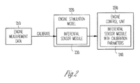
- FIG. 2 is a block diagram illustrating an inferential sensor module incorporated into an engine control unit, wherein the inferential sensor module includes parameters that were calibrated using an engine simulation model.
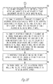
- FIGS. 3A and 3B are a diagram illustrating an embodiment of a process to calibrate an inferential sensor using an engine simulation model.
- One or more embodiments address the problems associated with manual and/or semi-manual calibration of inferential sensing by leveraging a technology that includes a functionality to automatically calibrate a medium-fidelity, grey box, control-oriented model (COM) of turbocharged engines and after treatment systems.
- COM medium-fidelity, grey box, control-oriented model
- an engineer can leverage a COM for calibrating inferential sensing algorithms (that is, the numerical value of theta).
- the COM can be a general medium fidelity model of an engine.
- the COM contains a set of nonlinear ordinary differential equations, and it is able to produce a wide variety of output signals from the engine such as pressures, flows, temperatures, and gas compositions.
- an engineer selects an engine simulation model ( FIG. 2 , No. 220 ) that is suited for his or her particular application.
- This model is normally based on physical first principles, but this is not an absolute necessity.
- the engine simulation model is used to predict a variety of engine properties (e.g. , pressures, temperatures, flows, and gas composition).
- the engine simulation model is calibrated to on-engine data containing model inputs signals (e.g. , actuator positions, injection quantities, and ambient conditions) and measurements of a various engine properties.
- Engine measurement data ( FIG. 2 , No. 210 ) contains model input signals (actuator position, injection quantity, ambient conditions, etc .).
- the engine measurement data are likely measured by test cell equipment, but also production sensors (offline, procedure of calibrating the ISA).
- the engine data include measurements of all inputs to the model and ISA, the inferred value(s), and possibly other signals which are predicted by the model.
- the calibration parameters of the ISA are calibrated such that the difference of the inferred signal predicted by the ISA and the one measured in the data is minimized.
- the calibrated inferential sensing module (specifically the calibration paramenter ⁇ ) is placed into an engine control unit ( FIG. 2 , Nos. 240, 250 ).
- the engine control unit containing the inferential sensing module can infer engine properties that are not directly measured on the production engine by using a set of on-engine measurements (e.g. pressures, temperatures, flows, and gas composition).
- the inferred signal can be of various types, e.g. pressure, temperature or likely even non-physical signals, or useful functions thereof such as an EGR fraction or a fraction of inert gases in the intake.
- the inferential sensing module in the engine control unit includes the calibration parameters that were computed as a function of measured or modeled engine data.
- the inferential module (f(y, ⁇ )) is integrated into overall engine simulation model. Then, the calibration of the engine simulation model is leveraged to calibrate the inferential sensor module, that is, to determine ⁇ . Thereafter, the numerical values of ⁇ are extracted from the COM and written to the ECU.
- This approach of using an engine simulation model and an inferential sensor module is systematic and optimal, and it works even if certain input signals (y) of algorithm (f) are not available. This cannot be said of the conventional manual and/or semi-manual approaches. Additionally, this approach is flexible for various inferential sensor structures whereas the calibration of the conventional approaches has to be modified for each case.
- the inputs y to the inferential sensor algorithm are theoretical (ideal) values which sometimes cannot be measured ideally. For example, temperatures cannot be usually measured without a small delay, typically a few seconds. This delay deteriorates the inferential sensor accuracy during transients. Also, it is hard to ensure the temperature measurement will not be affected by parasitic heat transfers to/from other locations. Additionally, flows often cannot be measured exactly at places where they should be measured. For example, it is hardly possible to measure the air flow into cylinders. However, it is possible to measure flow of the air to the intake manifold from which the air is supplied to the cylinders. This measurement can substitute for the former.
- the engine simulation model and inferential sensing module approach use model derived quantities regardless of whether meters are available and regardless of whether the meters are fast enough during transients.
- the model/module approach makes use of all measurements. Therefore, it is not necessary to decide whether the flow y will be derived from the pressure and/or temperature, or whether the sensor will be used. They can all be used.
- FIGS. 3A and 3B are a flowchart of an example process 300 for calibrating an inferential sensor using an engine simulation model.
- FIGS. 3A and 3B include a number of process blocks 305 - 350. Though arranged serially in the example of FIGS. 3A and 3B , other examples may reorder the blocks, omit one or more blocks, and/or execute two or more blocks in parallel using multiple processors or a single processor organized as two or more virtual machines or sub-processors. Moreover, still other examples can implement the blocks as one or more specific interconnected hardware or integrated circuit modules with related control and data signals communicated between and through the modules. Thus, any process flow is applicable to software, firmware, hardware, and hybrid implementations.
- an engine simulation model is stored in one or more of a computer processor and a computer storage device.
- the engine simulation model is configured to predict a plurality of engine properties.
- an inferential sensor module is incorporated into the engine simulation model.
- the engine simulation model is calibrated using measured on-engine data, the on-engine data comprising model input signals and measurements of a plurality of engine properties.
- the engine measurement data comprises one or more of a pressure, a flow, a temperature, a speed, a gas composition, and a function of a pressure, a flow, a temperature, a speed, or a gas composition.
- one or more parameters for the inferential sensor module are calibrated using one or more of engine measurement data and the engine simulation model.
- the parameters are calibrated such that a difference between an inferred signal predicted by the inferential sensor module and a signal measured on an engine is minimized.
- the computer processor is configured to calibrate the inferential sensor module when all inputs to the inferential sensor module are available via the engine measurement data but a subset of these inputs are replaced by signals predicted by the engine simulation model.
- the computer processor is configured to calibrate the inferential sensor module when one or more inputs to the inferential sensor module are unavailable in the engine measurement data that is used for calibration of the inferential sensor module, and to receive signals predicted by the engine simulation model and to substitute the engine simulation model signals for the unavailable engine measurement data.
- the inferential sensor module and the one or more calibrated parameters are transmitted to and stored in an engine control unit.
- the engine control unit uses the inferential sensor module and the one or more calibrated parameters to predict an inferred variable.
Landscapes
- Engineering & Computer Science (AREA)
- Physics & Mathematics (AREA)
- General Physics & Mathematics (AREA)
- Chemical & Material Sciences (AREA)
- Combustion & Propulsion (AREA)
- Mechanical Engineering (AREA)
- General Engineering & Computer Science (AREA)
- Computer Hardware Design (AREA)
- Microelectronics & Electronic Packaging (AREA)
- Combined Controls Of Internal Combustion Engines (AREA)
Abstract
Description
- The present disclosure relates to inferential sensing, and in an embodiment, but not by way of limitation, model-based calibration of inferential sensing.
- In diesel engine and other applications, very often control designers desire to create "inferential sensor" signals. These are signals in which a variable that is difficult or expensive to measure directly is inferred by combining the information received from one or more sensors, each measuring a different property. This set of sensor signals is input to an algorithm from which the desired quantity is inferred. A problem faced by the designer of inferential sensors is that they require significant engineering time and test cell measurements in order to calibrate the algorithms to achieve sufficient accuracy.
- This process is illustrated in graphic form in
FIG. 1 , wherein engine control unit (ECU) calibration personnel determine values of the calibration parameter (Θ inFIG. 1 ) such that the inferred value (Z inFIG. 1 ) is sufficiently accurate. In using the process ofFIG. 1 , in many cases, the calibration of inferential sensing algorithms is achieved by manual manipulation of the calibration parameter, that is, manipulating the numerical values of theta (Θ) until an acceptable performance is observed. This manual or semi-manual process requires a significant amount of expensive engineering and engine test cell time. - Specifically, to accomplish this, an engineer equips an engine with a set of sensors and makes the signals of these sensors (y in
FIG. 1 ) available to an engine control unit. The engineer further equips the engine to measure a desired engine output or variable (zmeas) using a sensor (which may be expensive, complex, not too robust, and/or not too accurate). The engineer then measures the variables y and zmeas at several operating points of the engine. As noted, manual or semi-manual techniques are used to calculate the numerical values for theta such that the modeled function z = f(y, theta) is close to the measured values (zmeas). Put another way, the norm of the difference between the estimated z and the measured zmeas is minimized. This process is then repeated at different engine operating points until the difference between the desired z and measured z is minimized. - Because this is a painstaking, time consuming, less than accurate, and expensive process, designers often "live with" substandard calibration, or spend significant costs on obtaining the desired accuracy.
-
FIG. 1 is a block diagram illustrating the use of and inferential sensing algorithm and calibration parameters to infer a value in an engine system. -
FIG. 2 is a block diagram illustrating an inferential sensor module incorporated into an engine control unit, wherein the inferential sensor module includes parameters that were calibrated using an engine simulation model. -
FIGS. 3A and3B are a diagram illustrating an embodiment of a process to calibrate an inferential sensor using an engine simulation model. - In the following description, reference is made to the accompanying drawings that form a part hereof, and in which is shown by way of illustration specific embodiments which may be practiced. These embodiments are described in sufficient detail to enable those skilled in the art to practice the invention, and it is to be understood that other embodiments may be utilized and that structural, electrical, and optical changes may be made without departing from the scope of the present invention. The following description of example embodiments is, therefore, not to be taken in a limited sense, and the scope of the present invention is defined by the appended claims.
- One or more embodiments address the problems associated with manual and/or semi-manual calibration of inferential sensing by leveraging a technology that includes a functionality to automatically calibrate a medium-fidelity, grey box, control-oriented model (COM) of turbocharged engines and after treatment systems. Specifically, in an embodiment, an engineer can leverage a COM for calibrating inferential sensing algorithms (that is, the numerical value of theta). The COM can be a general medium fidelity model of an engine. As is known in the art, the COM contains a set of nonlinear ordinary differential equations, and it is able to produce a wide variety of output signals from the engine such as pressures, flows, temperatures, and gas compositions. As is further known in the art, the equations in a particular COM depend on several factors, including the engine being used. While such a COM is too complex to be run in an engine control unit, its output can be leveraged to calibrate the simpler structure of the inferential sensing algorithm (z = f(y, theta)).
- Starting in an offline environment (i.e., not within an ECU), an engineer selects an engine simulation model (
FIG. 2 , No. 220) that is suited for his or her particular application. This model is normally based on physical first principles, but this is not an absolute necessity. The engine simulation model is used to predict a variety of engine properties (e.g., pressures, temperatures, flows, and gas composition). In an embodiment, the engine simulation model is calibrated to on-engine data containing model inputs signals (e.g., actuator positions, injection quantities, and ambient conditions) and measurements of a various engine properties. - Either during or after calibration of the engine simulation model, an inferential sensing module or algorithm is incorporated or embedded into the engine simulation model (
FIG. 2 , No. 230). Engine measurement data (FIG. 2 , No. 210) contains model input signals (actuator position, injection quantity, ambient conditions, etc.). The engine measurement data are likely measured by test cell equipment, but also production sensors (offline, procedure of calibrating the ISA). The engine data include measurements of all inputs to the model and ISA, the inferred value(s), and possibly other signals which are predicted by the model. Using the engine data and the engine model containing the ISA, the calibration parameters of the ISA are calibrated such that the difference of the inferred signal predicted by the ISA and the one measured in the data is minimized. - The calibrated inferential sensing module (specifically the calibration paramenter Θ) is placed into an engine control unit (
FIG. 2 , Nos. 240, 250). The engine control unit containing the inferential sensing module can infer engine properties that are not directly measured on the production engine by using a set of on-engine measurements (e.g. pressures, temperatures, flows, and gas composition). The inferred signal can be of various types, e.g. pressure, temperature or likely even non-physical signals, or useful functions thereof such as an EGR fraction or a fraction of inert gases in the intake. The inferential sensing module in the engine control unit includes the calibration parameters that were computed as a function of measured or modeled engine data. - Regarding the calibration of the inferential sensor module, the inferential module (f(y,θ)) is integrated into overall engine simulation model. Then, the calibration of the engine simulation model is leveraged to calibrate the inferential sensor module, that is, to determine θ. Thereafter, the numerical values of θ are extracted from the COM and written to the ECU. This approach of using an engine simulation model and an inferential sensor module is systematic and optimal, and it works even if certain input signals (y) of algorithm (f) are not available. This cannot be said of the conventional manual and/or semi-manual approaches. Additionally, this approach is flexible for various inferential sensor structures whereas the calibration of the conventional approaches has to be modified for each case.
- The advantages of the current approach, and the shortcomings of the manual/semi-manual approach, can be explained further. The inputs y to the inferential sensor algorithm are theoretical (ideal) values which sometimes cannot be measured ideally. For example, temperatures cannot be usually measured without a small delay, typically a few seconds. This delay deteriorates the inferential sensor accuracy during transients. Also, it is hard to ensure the temperature measurement will not be affected by parasitic heat transfers to/from other locations. Additionally, flows often cannot be measured exactly at places where they should be measured. For example, it is hardly possible to measure the air flow into cylinders. However, it is possible to measure flow of the air to the intake manifold from which the air is supplied to the cylinders. This measurement can substitute for the former. Again, there is a systematic error during transients, when the pressure in the intake manifold is changing quickly. Moreover, concentration meters are complicated devices where chemical reactions often take place. The dynamics of the measurements is often slow, temperature dependent, and may be affected by compounds other than those desired to be measured. Time response of the accurate gas analyzers may be tens of seconds. Faster analyzers may be less accurate. Also, it is difficult to measure some of the flows with sufficient accuracy. However, the pressures can be measured relatively easily with sufficient accuracy. The flow through an orifice may be inferred from the inlet and outlet pressures and the temperature.
- The examples of the previous paragraph show that in the equation z=f(y, θ), some of the data z and y are actually not available or not ideal. However, they are usually substituted with measurements which are close. For example, as noted, flow to cylinders is replaced by the flow into the intake manifold, gas temperature is replaced by thermometer temperature, and concentration in the cylinder is replaced by concentration in the tailpipe. Furthermore, some of the y's could actually be replaced by another inferential mechanism like pressures, temperatures, or flow calculations.
- However, these problems or concerns are adequately addressed by the approach of the current disclosure. In the engine simulation model or COM, all variables are available, including those which can hardly be measured. When calibrating the model fitting the measurements, all the information available in the measurements is utilized. Then, model-predicted flow is in fact calibrated by both flow measurements and the pressures/temperature measurements. Thus, the previously mentioned problems of data availability and accuracy issues are mitigated. Utilizing all measurements for model calibration and making model based predictions of y exact values (not replacing them with close substitutes) solves both the availability and accuracy issues. The accuracy of the new approach is better, especially during transients because of the more accurate value for y (not systematically delayed).
- In summary, the engine simulation model and inferential sensing module approach use model derived quantities regardless of whether meters are available and regardless of whether the meters are fast enough during transients. The model/module approach makes use of all measurements. Therefore, it is not necessary to decide whether the flow y will be derived from the pressure and/or temperature, or whether the sensor will be used. They can all be used. Lastly, the novel approach does not augment the equation z=f(y, θ) with other parameters to reconstruct some quantities. Rather, it uses the model for this purpose. In the novel approach the empirical part is delimited to the minimum, i.e. z=f(y, θ). It is not augmented with more empirical equations because the first principles based model is used.
-
FIGS. 3A and3B are a flowchart of anexample process 300 for calibrating an inferential sensor using an engine simulation model.FIGS. 3A and3B include a number of process blocks 305 - 350. Though arranged serially in the example ofFIGS. 3A and3B , other examples may reorder the blocks, omit one or more blocks, and/or execute two or more blocks in parallel using multiple processors or a single processor organized as two or more virtual machines or sub-processors. Moreover, still other examples can implement the blocks as one or more specific interconnected hardware or integrated circuit modules with related control and data signals communicated between and through the modules. Thus, any process flow is applicable to software, firmware, hardware, and hybrid implementations. - Referring to
FIGS. 3A and3B , at 305, an engine simulation model is stored in one or more of a computer processor and a computer storage device. At 310, the engine simulation model is configured to predict a plurality of engine properties. At 315, an inferential sensor module is incorporated into the engine simulation model. At 320, the engine simulation model is calibrated using measured on-engine data, the on-engine data comprising model input signals and measurements of a plurality of engine properties. At 325, the engine measurement data comprises one or more of a pressure, a flow, a temperature, a speed, a gas composition, and a function of a pressure, a flow, a temperature, a speed, or a gas composition. At 330, one or more parameters for the inferential sensor module are calibrated using one or more of engine measurement data and the engine simulation model. The parameters are calibrated such that a difference between an inferred signal predicted by the inferential sensor module and a signal measured on an engine is minimized. At 335, the computer processor is configured to calibrate the inferential sensor module when all inputs to the inferential sensor module are available via the engine measurement data but a subset of these inputs are replaced by signals predicted by the engine simulation model. At 340, the computer processor is configured to calibrate the inferential sensor module when one or more inputs to the inferential sensor module are unavailable in the engine measurement data that is used for calibration of the inferential sensor module, and to receive signals predicted by the engine simulation model and to substitute the engine simulation model signals for the unavailable engine measurement data. At 345, the inferential sensor module and the one or more calibrated parameters are transmitted to and stored in an engine control unit. At 350, the engine control unit uses the inferential sensor module and the one or more calibrated parameters to predict an inferred variable. - It should be understood that there exist implementations of other variations and modifications of the invention and its various aspects, as may be readily apparent, for example, to those of ordinary skill in the art, and that the invention is not limited by specific embodiments described herein. Features and embodiments described above may be combined with each other in different combinations. It is therefore contemplated to cover any and all modifications, variations, combinations or equivalents that fall within the scope of the present invention.
- The Abstract is provided to comply with 37 C.F.R. §1.72(b) and will allow the reader to quickly ascertain the nature and gist of the technical disclosure. It is submitted with the understanding that it will not be used to interpret or limit the scope or meaning of the claims.
- In the foregoing description of the embodiments, various features are grouped together in a single embodiment for the purpose of streamlining the disclosure. This method of disclosure is not to be interpreted as reflecting that the claimed embodiments have more features than are expressly recited in each claim. Rather, as the following claims reflect, inventive subject matter lies in less than all features of a single disclosed embodiment. Thus the following claims are hereby incorporated into the Description of the Embodiments, with each claim standing on its own as a separate example embodiment.
Claims (10)
- A system comprising:one or more of a computer processor (250) and a computer storage device (240) configured to:store an engine simulation model; (305)incorporate an inferential sensor module into the engine simulation model; (315) andcalibrate one or more parameters for the inferential sensor module using one or more of engine measurement data and the engine simulation model, such that a difference between an inferred signal predicted by the inferential sensor module and a signal measured on an engine is minimized. (320)
- The system of claim 1, wherein the engine simulation model is calibrated using measured on-engine data, the on-engine data comprising model input signals and measurements of a plurality of engine properties. (320)
- The system of claim 1, wherein the computer processor is configured to calibrate the inferential sensor module when all inputs to the inferential sensor module are available via the engine measurement data but a subset of these inputs are replaced by signals predicted by the engine simulation model. (335)
- The system of claim 1, wherein the computer processor is configured to calibrate the inferential sensor module when one or more inputs to the inferential sensor module are unavailable in the engine measurement data that is used for calibration of the inferential sensor module, and to receive signals predicted by the engine simulation model and to substitute the engine simulation model signals for the unavailable engine measurement data. (340)
- A process comprising:storing an engine simulation model into one or more of a computer processor and a computer storage device; (305)incorporating an inferential sensor module into the engine simulation model; (315) andcalibrating one or more parameters for the inferential sensor module using one or more of engine measurement data and the engine simulation model, such that a difference between an inferred signal predicted by the inferential sensor module and a signal measured on an engine is minimized. (320)
- The process of claim 5, comprising transmitting to an engine control unit the inferential sensor module and the one or more calibrated parameters. (345)
- The process of claim 5, comprising calibrating the inferential sensor module when all inputs to the inferential sensor module are available via the engine measurement data but a subset of these inputs are replaced by signals predicted by the engine simulation module. (335)
- The process of claim 5, comprising calibrating the inferential sensor module when one or more inputs to the inferential sensor module are unavailable in the engine measurement data that is used for calibration of the inferential sensor module, and receiving signals predicted by the engine simulation model and substituting the engine simulation model signals for the unavailable engine measurement data. (340)
- A computer readable storage device (250) comprising instructions (240) that when executed by a processor execute a process comprising:storing an engine simulation model into one or more of a computer processor and a computer storage device; (305)incorporating an inferential sensor module into the engine simulation model; (315) andcalibrating one or more parameters for the inferential sensor module using one or more of engine measurement data and the engine simulation model, such that a difference between an inferred signal predicted by the inferential sensor module and a signal measured on an engine is minimized. (320)
- The computer readable storage medium of claim 9, wherein the engine control unit uses the inferential sensor module and the one or more calibrated parameters to predict an inferred variable. (350)
Applications Claiming Priority (1)
| Application Number | Priority Date | Filing Date | Title |
|---|---|---|---|
| US13/331,812 US8700546B2 (en) | 2011-12-20 | 2011-12-20 | Model based calibration of inferential sensing |
Publications (3)
| Publication Number | Publication Date |
|---|---|
| EP2607861A2 true EP2607861A2 (en) | 2013-06-26 |
| EP2607861A3 EP2607861A3 (en) | 2017-11-29 |
| EP2607861B1 EP2607861B1 (en) | 2020-07-08 |
Family
ID=47678488
Family Applications (1)
| Application Number | Title | Priority Date | Filing Date |
|---|---|---|---|
| EP12197281.4A Active EP2607861B1 (en) | 2011-12-20 | 2012-12-14 | Model based calibration of inferential sensing |
Country Status (3)
| Country | Link |
|---|---|
| US (1) | US8700546B2 (en) |
| EP (1) | EP2607861B1 (en) |
| JP (1) | JP2013144975A (en) |
Families Citing this family (6)
| Publication number | Priority date | Publication date | Assignee | Title |
|---|---|---|---|---|
| EP3018541B1 (en) * | 2014-11-04 | 2023-10-25 | Garrett Transportation I Inc. | Configurable inferential sensor for vehicle control systems |
| CN106285960B (en) * | 2015-05-12 | 2019-03-01 | 北京汽车动力总成有限公司 | A kind of calculation method and device of vehicle simulation parameter |
| CN113624498B (en) * | 2020-05-09 | 2024-01-16 | 中国航发商用航空发动机有限责任公司 | Device, method and simulation system for measuring signal of pulse pressure sensor |
| US11434843B1 (en) | 2021-05-21 | 2022-09-06 | Garrett Transportation I Inc. | Engine mass flow observer with fault mitigation |
| US11687071B2 (en) | 2021-08-19 | 2023-06-27 | Garrett Transportation I Inc. | Methods of health degradation estimation and fault isolation for system health monitoring |
| US12008848B2 (en) | 2021-09-22 | 2024-06-11 | Garrett Transportation I Inc. | Adaptive fuel and charge consumption estimation in powertrain systems |
Family Cites Families (7)
| Publication number | Priority date | Publication date | Assignee | Title |
|---|---|---|---|---|
| US5539638A (en) * | 1993-08-05 | 1996-07-23 | Pavilion Technologies, Inc. | Virtual emissions monitor for automobile |
| US20030018457A1 (en) * | 2001-03-13 | 2003-01-23 | Lett Gregory Scott | Biological modeling utilizing image data |
| US7660694B2 (en) * | 2005-07-11 | 2010-02-09 | Chrysler Group Llc | Arrangement for determining an initial internal battery temperature |
| US7499842B2 (en) * | 2005-11-18 | 2009-03-03 | Caterpillar Inc. | Process model based virtual sensor and method |
| JP2008021092A (en) * | 2006-07-12 | 2008-01-31 | Fanuc Ltd | Simulation apparatus of robot system |
| US20080154811A1 (en) * | 2006-12-21 | 2008-06-26 | Caterpillar Inc. | Method and system for verifying virtual sensors |
| US7787969B2 (en) * | 2007-06-15 | 2010-08-31 | Caterpillar Inc | Virtual sensor system and method |
-
2011
- 2011-12-20 US US13/331,812 patent/US8700546B2/en active Active
-
2012
- 2012-12-14 EP EP12197281.4A patent/EP2607861B1/en active Active
- 2012-12-18 JP JP2012275507A patent/JP2013144975A/en active Pending
Non-Patent Citations (1)
| Title |
|---|
| None |
Also Published As
| Publication number | Publication date |
|---|---|
| JP2013144975A (en) | 2013-07-25 |
| EP2607861A3 (en) | 2017-11-29 |
| US8700546B2 (en) | 2014-04-15 |
| US20130159225A1 (en) | 2013-06-20 |
| EP2607861B1 (en) | 2020-07-08 |
Similar Documents
| Publication | Publication Date | Title |
|---|---|---|
| US8700546B2 (en) | Model based calibration of inferential sensing | |
| CN107479527B (en) | Apparatus for diagnosing deterioration | |
| EP2837805A2 (en) | Engine operation with air system model | |
| CN101666697A (en) | Method and apparatus for storing measurement data on a vacuum gauge structure | |
| CN115615522B (en) | Test and analysis methods for turbine flow sensors and intelligent flow measurement equipment | |
| CN115326276B (en) | Temperature compensation of Pirani vacuum gauge, calculation method and device of ambient vacuum | |
| CN111075586A (en) | A kind of air intake flow sensor inspection method | |
| CN105035355A (en) | Thermal load power simulation method and thermal load simulation system | |
| CN117786464A (en) | An abnormality early warning method and system for an electric constant-temperature incubator | |
| CN116127605A (en) | Method and device for determining thermal management performance of whole vehicle, computer equipment and storage medium | |
| CN115452062A (en) | Flow measurement method, device, computer equipment and storage medium | |
| CN117824772A (en) | A natural gas flow metering adaptive compensation method, system, terminal and medium | |
| US7725283B2 (en) | Methods and apparatus for a virtual test cell | |
| CN115907054A (en) | Method, system, storage medium and terminal for predicting compression factor of high-pressure natural gas | |
| JP6564299B2 (en) | Characteristic model identification method, characteristic model identification device, and intelligent sensor | |
| CN118425435B (en) | Prediction method, prediction apparatus, computer device, readable storage medium, and program product | |
| Mecagni et al. | Control-Oriented Exhaust Gas Temperature Modelling Based on Wiebe Equation | |
| CN116818180A (en) | STM32 and LSTM-based temperature compensation method and system for pressure sensor for valve | |
| CN115265805B (en) | A temperature calibration method based on thermopile, storage medium and related equipment | |
| KR20120103642A (en) | Method for exhaust gas recirculation | |
| Gutjahr et al. | AUTOMATED OPTIMIZATION OF PHYSICS-BASED SENSOR MODELS FOR EMBEDDED CONTROL SYSTEMS | |
| Joswa Rajan et al. | Industrialization of base calibration methods for ECU-functions exemplary for air charge determination | |
| Mai et al. | Impact of measurement uncertainty in the characteristic maps of a turbocharger on engine performance | |
| Mrosek et al. | Parameter Estimation for Physical Based Air Path Models of Turbocharged Diesel Engines—An Experience Based Guidance | |
| CN118424547B (en) | A Comprehensive Compensation Method for Differential Pressure Transmitters Based on Kriging Interpolation and Cubic Spline Interpolation |
Legal Events
| Date | Code | Title | Description |
|---|---|---|---|
| 17P | Request for examination filed |
Effective date: 20121214 |
|
| AK | Designated contracting states |
Kind code of ref document: A2 Designated state(s): AL AT BE BG CH CY CZ DE DK EE ES FI FR GB GR HR HU IE IS IT LI LT LU LV MC MK MT NL NO PL PT RO RS SE SI SK SM TR |
|
| AX | Request for extension of the european patent |
Extension state: BA ME |
|
| PUAI | Public reference made under article 153(3) epc to a published international application that has entered the european phase |
Free format text: ORIGINAL CODE: 0009012 |
|
| RAP1 | Party data changed (applicant data changed or rights of an application transferred) |
Owner name: HONEYWELL INTERNATIONAL INC. |
|
| PUAL | Search report despatched |
Free format text: ORIGINAL CODE: 0009013 |
|
| STAA | Information on the status of an ep patent application or granted ep patent |
Free format text: STATUS: EXAMINATION IS IN PROGRESS |
|
| AK | Designated contracting states |
Kind code of ref document: A3 Designated state(s): AL AT BE BG CH CY CZ DE DK EE ES FI FR GB GR HR HU IE IS IT LI LT LU LV MC MK MT NL NO PL PT RO RS SE SI SK SM TR |
|
| AX | Request for extension of the european patent |
Extension state: BA ME |
|
| RIC1 | Information provided on ipc code assigned before grant |
Ipc: G05B 13/04 20060101ALI20171023BHEP Ipc: F02D 41/14 20060101ALN20171023BHEP Ipc: G01D 18/00 20060101AFI20171023BHEP |
|
| 17Q | First examination report despatched |
Effective date: 20171121 |
|
| RAP1 | Party data changed (applicant data changed or rights of an application transferred) |
Owner name: GARRETT TRANSPORTATION I INC. |
|
| RIC1 | Information provided on ipc code assigned before grant |
Ipc: G01D 18/00 20060101AFI20200123BHEP Ipc: F02D 41/14 20060101ALN20200123BHEP Ipc: F02D 41/26 20060101ALI20200123BHEP Ipc: F02D 41/24 20060101ALI20200123BHEP |
|
| GRAP | Despatch of communication of intention to grant a patent |
Free format text: ORIGINAL CODE: EPIDOSNIGR1 |
|
| STAA | Information on the status of an ep patent application or granted ep patent |
Free format text: STATUS: GRANT OF PATENT IS INTENDED |
|
| INTG | Intention to grant announced |
Effective date: 20200228 |
|
| GRAS | Grant fee paid |
Free format text: ORIGINAL CODE: EPIDOSNIGR3 |
|
| GRAA | (expected) grant |
Free format text: ORIGINAL CODE: 0009210 |
|
| STAA | Information on the status of an ep patent application or granted ep patent |
Free format text: STATUS: THE PATENT HAS BEEN GRANTED |
|
| AK | Designated contracting states |
Kind code of ref document: B1 Designated state(s): AL AT BE BG CH CY CZ DE DK EE ES FI FR GB GR HR HU IE IS IT LI LT LU LV MC MK MT NL NO PL PT RO RS SE SI SK SM TR |
|
| REG | Reference to a national code |
Ref country code: GB Ref legal event code: FG4D |
|
| REG | Reference to a national code |
Ref country code: AT Ref legal event code: REF Ref document number: 1288945 Country of ref document: AT Kind code of ref document: T Effective date: 20200715 Ref country code: CH Ref legal event code: EP |
|
| REG | Reference to a national code |
Ref country code: DE Ref legal event code: R096 Ref document number: 602012071108 Country of ref document: DE |
|
| REG | Reference to a national code |
Ref country code: IE Ref legal event code: FG4D |
|
| REG | Reference to a national code |
Ref country code: LT Ref legal event code: MG4D |
|
| REG | Reference to a national code |
Ref country code: AT Ref legal event code: MK05 Ref document number: 1288945 Country of ref document: AT Kind code of ref document: T Effective date: 20200708 |
|
| REG | Reference to a national code |
Ref country code: NL Ref legal event code: MP Effective date: 20200708 |
|
| PG25 | Lapsed in a contracting state [announced via postgrant information from national office to epo] |
Ref country code: AT Free format text: LAPSE BECAUSE OF FAILURE TO SUBMIT A TRANSLATION OF THE DESCRIPTION OR TO PAY THE FEE WITHIN THE PRESCRIBED TIME-LIMIT Effective date: 20200708 Ref country code: NO Free format text: LAPSE BECAUSE OF FAILURE TO SUBMIT A TRANSLATION OF THE DESCRIPTION OR TO PAY THE FEE WITHIN THE PRESCRIBED TIME-LIMIT Effective date: 20201008 Ref country code: GR Free format text: LAPSE BECAUSE OF FAILURE TO SUBMIT A TRANSLATION OF THE DESCRIPTION OR TO PAY THE FEE WITHIN THE PRESCRIBED TIME-LIMIT Effective date: 20201009 Ref country code: BG Free format text: LAPSE BECAUSE OF FAILURE TO SUBMIT A TRANSLATION OF THE DESCRIPTION OR TO PAY THE FEE WITHIN THE PRESCRIBED TIME-LIMIT Effective date: 20201008 Ref country code: ES Free format text: LAPSE BECAUSE OF FAILURE TO SUBMIT A TRANSLATION OF THE DESCRIPTION OR TO PAY THE FEE WITHIN THE PRESCRIBED TIME-LIMIT Effective date: 20200708 Ref country code: HR Free format text: LAPSE BECAUSE OF FAILURE TO SUBMIT A TRANSLATION OF THE DESCRIPTION OR TO PAY THE FEE WITHIN THE PRESCRIBED TIME-LIMIT Effective date: 20200708 Ref country code: SE Free format text: LAPSE BECAUSE OF FAILURE TO SUBMIT A TRANSLATION OF THE DESCRIPTION OR TO PAY THE FEE WITHIN THE PRESCRIBED TIME-LIMIT Effective date: 20200708 Ref country code: PT Free format text: LAPSE BECAUSE OF FAILURE TO SUBMIT A TRANSLATION OF THE DESCRIPTION OR TO PAY THE FEE WITHIN THE PRESCRIBED TIME-LIMIT Effective date: 20201109 Ref country code: LT Free format text: LAPSE BECAUSE OF FAILURE TO SUBMIT A TRANSLATION OF THE DESCRIPTION OR TO PAY THE FEE WITHIN THE PRESCRIBED TIME-LIMIT Effective date: 20200708 Ref country code: FI Free format text: LAPSE BECAUSE OF FAILURE TO SUBMIT A TRANSLATION OF THE DESCRIPTION OR TO PAY THE FEE WITHIN THE PRESCRIBED TIME-LIMIT Effective date: 20200708 |
|
| PG25 | Lapsed in a contracting state [announced via postgrant information from national office to epo] |
Ref country code: IS Free format text: LAPSE BECAUSE OF FAILURE TO SUBMIT A TRANSLATION OF THE DESCRIPTION OR TO PAY THE FEE WITHIN THE PRESCRIBED TIME-LIMIT Effective date: 20201108 Ref country code: LV Free format text: LAPSE BECAUSE OF FAILURE TO SUBMIT A TRANSLATION OF THE DESCRIPTION OR TO PAY THE FEE WITHIN THE PRESCRIBED TIME-LIMIT Effective date: 20200708 Ref country code: RS Free format text: LAPSE BECAUSE OF FAILURE TO SUBMIT A TRANSLATION OF THE DESCRIPTION OR TO PAY THE FEE WITHIN THE PRESCRIBED TIME-LIMIT Effective date: 20200708 Ref country code: PL Free format text: LAPSE BECAUSE OF FAILURE TO SUBMIT A TRANSLATION OF THE DESCRIPTION OR TO PAY THE FEE WITHIN THE PRESCRIBED TIME-LIMIT Effective date: 20200708 |
|
| PG25 | Lapsed in a contracting state [announced via postgrant information from national office to epo] |
Ref country code: NL Free format text: LAPSE BECAUSE OF FAILURE TO SUBMIT A TRANSLATION OF THE DESCRIPTION OR TO PAY THE FEE WITHIN THE PRESCRIBED TIME-LIMIT Effective date: 20200708 |
|
| REG | Reference to a national code |
Ref country code: DE Ref legal event code: R097 Ref document number: 602012071108 Country of ref document: DE |
|
| PG25 | Lapsed in a contracting state [announced via postgrant information from national office to epo] |
Ref country code: RO Free format text: LAPSE BECAUSE OF FAILURE TO SUBMIT A TRANSLATION OF THE DESCRIPTION OR TO PAY THE FEE WITHIN THE PRESCRIBED TIME-LIMIT Effective date: 20200708 Ref country code: SM Free format text: LAPSE BECAUSE OF FAILURE TO SUBMIT A TRANSLATION OF THE DESCRIPTION OR TO PAY THE FEE WITHIN THE PRESCRIBED TIME-LIMIT Effective date: 20200708 Ref country code: IT Free format text: LAPSE BECAUSE OF FAILURE TO SUBMIT A TRANSLATION OF THE DESCRIPTION OR TO PAY THE FEE WITHIN THE PRESCRIBED TIME-LIMIT Effective date: 20200708 Ref country code: DK Free format text: LAPSE BECAUSE OF FAILURE TO SUBMIT A TRANSLATION OF THE DESCRIPTION OR TO PAY THE FEE WITHIN THE PRESCRIBED TIME-LIMIT Effective date: 20200708 Ref country code: EE Free format text: LAPSE BECAUSE OF FAILURE TO SUBMIT A TRANSLATION OF THE DESCRIPTION OR TO PAY THE FEE WITHIN THE PRESCRIBED TIME-LIMIT Effective date: 20200708 Ref country code: CZ Free format text: LAPSE BECAUSE OF FAILURE TO SUBMIT A TRANSLATION OF THE DESCRIPTION OR TO PAY THE FEE WITHIN THE PRESCRIBED TIME-LIMIT Effective date: 20200708 |
|
| PLBE | No opposition filed within time limit |
Free format text: ORIGINAL CODE: 0009261 |
|
| STAA | Information on the status of an ep patent application or granted ep patent |
Free format text: STATUS: NO OPPOSITION FILED WITHIN TIME LIMIT |
|
| PG25 | Lapsed in a contracting state [announced via postgrant information from national office to epo] |
Ref country code: AL Free format text: LAPSE BECAUSE OF FAILURE TO SUBMIT A TRANSLATION OF THE DESCRIPTION OR TO PAY THE FEE WITHIN THE PRESCRIBED TIME-LIMIT Effective date: 20200708 |
|
| 26N | No opposition filed |
Effective date: 20210409 |
|
| PG25 | Lapsed in a contracting state [announced via postgrant information from national office to epo] |
Ref country code: SK Free format text: LAPSE BECAUSE OF FAILURE TO SUBMIT A TRANSLATION OF THE DESCRIPTION OR TO PAY THE FEE WITHIN THE PRESCRIBED TIME-LIMIT Effective date: 20200708 |
|
| REG | Reference to a national code |
Ref country code: CH Ref legal event code: PL |
|
| PG25 | Lapsed in a contracting state [announced via postgrant information from national office to epo] |
Ref country code: SI Free format text: LAPSE BECAUSE OF FAILURE TO SUBMIT A TRANSLATION OF THE DESCRIPTION OR TO PAY THE FEE WITHIN THE PRESCRIBED TIME-LIMIT Effective date: 20200708 Ref country code: MC Free format text: LAPSE BECAUSE OF FAILURE TO SUBMIT A TRANSLATION OF THE DESCRIPTION OR TO PAY THE FEE WITHIN THE PRESCRIBED TIME-LIMIT Effective date: 20200708 |
|
| REG | Reference to a national code |
Ref country code: BE Ref legal event code: MM Effective date: 20201231 |
|
| PG25 | Lapsed in a contracting state [announced via postgrant information from national office to epo] |
Ref country code: IE Free format text: LAPSE BECAUSE OF NON-PAYMENT OF DUE FEES Effective date: 20201214 Ref country code: LU Free format text: LAPSE BECAUSE OF NON-PAYMENT OF DUE FEES Effective date: 20201214 |
|
| PG25 | Lapsed in a contracting state [announced via postgrant information from national office to epo] |
Ref country code: CH Free format text: LAPSE BECAUSE OF NON-PAYMENT OF DUE FEES Effective date: 20201231 Ref country code: LI Free format text: LAPSE BECAUSE OF NON-PAYMENT OF DUE FEES Effective date: 20201231 |
|
| PG25 | Lapsed in a contracting state [announced via postgrant information from national office to epo] |
Ref country code: TR Free format text: LAPSE BECAUSE OF FAILURE TO SUBMIT A TRANSLATION OF THE DESCRIPTION OR TO PAY THE FEE WITHIN THE PRESCRIBED TIME-LIMIT Effective date: 20200708 Ref country code: MT Free format text: LAPSE BECAUSE OF FAILURE TO SUBMIT A TRANSLATION OF THE DESCRIPTION OR TO PAY THE FEE WITHIN THE PRESCRIBED TIME-LIMIT Effective date: 20200708 Ref country code: CY Free format text: LAPSE BECAUSE OF FAILURE TO SUBMIT A TRANSLATION OF THE DESCRIPTION OR TO PAY THE FEE WITHIN THE PRESCRIBED TIME-LIMIT Effective date: 20200708 |
|
| PG25 | Lapsed in a contracting state [announced via postgrant information from national office to epo] |
Ref country code: MK Free format text: LAPSE BECAUSE OF FAILURE TO SUBMIT A TRANSLATION OF THE DESCRIPTION OR TO PAY THE FEE WITHIN THE PRESCRIBED TIME-LIMIT Effective date: 20200708 |
|
| PG25 | Lapsed in a contracting state [announced via postgrant information from national office to epo] |
Ref country code: BE Free format text: LAPSE BECAUSE OF NON-PAYMENT OF DUE FEES Effective date: 20201231 |
|
| P01 | Opt-out of the competence of the unified patent court (upc) registered |
Effective date: 20230424 |
|
| PGFP | Annual fee paid to national office [announced via postgrant information from national office to epo] |
Ref country code: GB Payment date: 20251223 Year of fee payment: 14 |
|
| PGFP | Annual fee paid to national office [announced via postgrant information from national office to epo] |
Ref country code: FR Payment date: 20251230 Year of fee payment: 14 |
|
| PGFP | Annual fee paid to national office [announced via postgrant information from national office to epo] |
Ref country code: DE Payment date: 20251229 Year of fee payment: 14 |