EP2607729A1 - Side seal for linear guide - Google Patents
Side seal for linear guide Download PDFInfo
- Publication number
- EP2607729A1 EP2607729A1 EP11817889.6A EP11817889A EP2607729A1 EP 2607729 A1 EP2607729 A1 EP 2607729A1 EP 11817889 A EP11817889 A EP 11817889A EP 2607729 A1 EP2607729 A1 EP 2607729A1
- Authority
- EP
- European Patent Office
- Prior art keywords
- main body
- seal main
- housing
- seal
- holder
- Prior art date
- Legal status (The legal status is an assumption and is not a legal conclusion. Google has not performed a legal analysis and makes no representation as to the accuracy of the status listed.)
- Granted
Links
Images


Classifications
-
- F—MECHANICAL ENGINEERING; LIGHTING; HEATING; WEAPONS; BLASTING
- F16—ENGINEERING ELEMENTS AND UNITS; GENERAL MEASURES FOR PRODUCING AND MAINTAINING EFFECTIVE FUNCTIONING OF MACHINES OR INSTALLATIONS; THERMAL INSULATION IN GENERAL
- F16C—SHAFTS; FLEXIBLE SHAFTS; ELEMENTS OR CRANKSHAFT MECHANISMS; ROTARY BODIES OTHER THAN GEARING ELEMENTS; BEARINGS
- F16C33/00—Parts of bearings; Special methods for making bearings or parts thereof
- F16C33/72—Sealings
- F16C33/76—Sealings of ball or roller bearings
- F16C33/80—Labyrinth sealings
-
- F—MECHANICAL ENGINEERING; LIGHTING; HEATING; WEAPONS; BLASTING
- F16—ENGINEERING ELEMENTS AND UNITS; GENERAL MEASURES FOR PRODUCING AND MAINTAINING EFFECTIVE FUNCTIONING OF MACHINES OR INSTALLATIONS; THERMAL INSULATION IN GENERAL
- F16C—SHAFTS; FLEXIBLE SHAFTS; ELEMENTS OR CRANKSHAFT MECHANISMS; ROTARY BODIES OTHER THAN GEARING ELEMENTS; BEARINGS
- F16C29/00—Bearings for parts moving only linearly
- F16C29/04—Ball or roller bearings
- F16C29/06—Ball or roller bearings in which the rolling bodies circulate partly without carrying load
- F16C29/0633—Ball or roller bearings in which the rolling bodies circulate partly without carrying load with a bearing body defining a U-shaped carriage, i.e. surrounding a guide rail or track on three sides
- F16C29/0635—Ball or roller bearings in which the rolling bodies circulate partly without carrying load with a bearing body defining a U-shaped carriage, i.e. surrounding a guide rail or track on three sides whereby the return paths are provided as bores in a main body of the U-shaped carriage, e.g. the main body of the U-shaped carriage is a single part with end caps provided at each end
- F16C29/0638—Ball or roller bearings in which the rolling bodies circulate partly without carrying load with a bearing body defining a U-shaped carriage, i.e. surrounding a guide rail or track on three sides whereby the return paths are provided as bores in a main body of the U-shaped carriage, e.g. the main body of the U-shaped carriage is a single part with end caps provided at each end with balls
- F16C29/0642—Ball or roller bearings in which the rolling bodies circulate partly without carrying load with a bearing body defining a U-shaped carriage, i.e. surrounding a guide rail or track on three sides whereby the return paths are provided as bores in a main body of the U-shaped carriage, e.g. the main body of the U-shaped carriage is a single part with end caps provided at each end with balls with four rows of balls
-
- F—MECHANICAL ENGINEERING; LIGHTING; HEATING; WEAPONS; BLASTING
- F16—ENGINEERING ELEMENTS AND UNITS; GENERAL MEASURES FOR PRODUCING AND MAINTAINING EFFECTIVE FUNCTIONING OF MACHINES OR INSTALLATIONS; THERMAL INSULATION IN GENERAL
- F16C—SHAFTS; FLEXIBLE SHAFTS; ELEMENTS OR CRANKSHAFT MECHANISMS; ROTARY BODIES OTHER THAN GEARING ELEMENTS; BEARINGS
- F16C29/00—Bearings for parts moving only linearly
- F16C29/08—Arrangements for covering or protecting the ways
- F16C29/084—Arrangements for covering or protecting the ways fixed to the carriage or bearing body movable along the guide rail or track
- F16C29/086—Seals being essentially U-shaped, e.g. for a U-shaped carriage
-
- F—MECHANICAL ENGINEERING; LIGHTING; HEATING; WEAPONS; BLASTING
- F16—ENGINEERING ELEMENTS AND UNITS; GENERAL MEASURES FOR PRODUCING AND MAINTAINING EFFECTIVE FUNCTIONING OF MACHINES OR INSTALLATIONS; THERMAL INSULATION IN GENERAL
- F16C—SHAFTS; FLEXIBLE SHAFTS; ELEMENTS OR CRANKSHAFT MECHANISMS; ROTARY BODIES OTHER THAN GEARING ELEMENTS; BEARINGS
- F16C2300/00—Application independent of particular apparatuses
- F16C2300/02—General use or purpose, i.e. no use, purpose, special adaptation or modification indicated or a wide variety of uses mentioned
Definitions
- the present invention relates to side seals for linear guides, and more specifically to side seals attached to both ends in the sliding direction of a slider that slides along a guide rail, and in contact with the guide rail to prevent entrance of foreign materials such as refuses.
- Side seals to be attached to the slider of a linear guide have a structure such that a seal main body formed of an elastic material such as elastomer is sandwiched between a holder and a cover as disclosed in, for example, the following Patent Document 1. According to such a structure, the soft seal main body is held between the hard holder and cover so that an assembly can be made. This facilitates handling of such an assembly at the time of assembling and improves the assembling precision.
- Patent Literature 1 JP 2007-211900 A
- the present invention has been made in view of the above-explained technical issue, and it is an object of the present invention to provide a side seal of the linear guide which needs no complete cutting or elimination of the gate burr of a seal main body and which is good at assembling performance.
- a side seal of a linear guide attached to each of both ends of a slider of the linear guide in a sliding direction of the slider and sliding in contact with a guide rail
- the side seal comprising: a seal main body formed by shaping an elastic material using a mold, and sliding in contact with the guide rail; and a holder for housing and holding the seal main body, a gate burr housing for housing an elastic-material gate burr of the seal main body being formed in a seal main body housing of the holder.
- the gate burr housing may be formed at a front side of the seal main body housing of the holder, and the elastic-material gate burr of the seal main body may be formed at a corresponding portion to the gate burr housing.
- the gate burr housing may be formed at a rear side of the seal main body housing of the holder and the elastic-material gate burr of the seal main body may be formed at a corresponding portion to the gate burr housing.
- a cover may cover the seal main body housed in the seal main body housing of the holder.
- the side seal of the linear guide is attached to each of both ends of a slider of the linear guide in a sliding direction of the slider and sliding in contact with a guide rail, the side seal comprising: a seal main body formed by shaping an elastic material using a mold, and sliding in contact with the guide rail; and a holder for housing and holding the seal main body, a gate burr housing for housing an elastic-material gate burr of the seal main body being formed in a seal main body housing of the holder. According to such a structure, it becomes unnecessary to completely cut or eliminate the elastic-material gate burr of the seal main body.
- the labor work can be reduced by what corresponds to such unnecessity, and the elastic-material gate burr of the seal main body can be simply housed in the gate burr housing of the seal main body housing of the holder, thereby improving the workability.
- the gate burr housing may be formed at a front side of the seal main body housing of the holder, and the elastic-material gate burr of the seal main body may be formed at a corresponding portion to the gate burr housing.
- the elastic-material gate burr can be used to distinguish the orientation of the seal main body such as the front and rear sides and to prevent a false assembling, thereby improving the assembling performance
- the gate burr housing may be formed at a rear side of the seal main body housing of the holder and the elastic-material gate burr of the seal main body may be formed at a corresponding portion to the gate burr housing
- the elastic-material gate burr can be used to distinguish the orientation of the seal main body such as the front and rear sides and to present a false assembling, thereby improving the assembling performance, while at the same time, preventing the seal main body from being dropped off from the holder.
- the side seal of the linear guide may further include a cover for covering the seal main body housed in the seal main body housing of the holder According to such a structure, the side seal can be made as an assembly, which facilitates the handling at the time of assembling and improves the assembling precision.
- FIG. 1 is a perspective view showing an overall structure of a linear guide using a side seal according to the present embodiment.
- the linear guide includes: a lengthened guide rail 1 having a substantially rectangular cross section; and a slider 2 which is mounted and provided on the guide rail 1 in a slidable manner in the lengthwise direction of the guide rail and which has a substantially letter U-shaped lateral cross section.
- the guide rail 1 has ball guiding grooves 3a which are formed of two inclined surfaces formed in the lengthwise direction of the guide rail to be adjacent to each other and having a substantially triangular cross section and which are formed in each side face of the guide rail orthogonal to the lengthwise direction.
- the guide rail 1 also has a plurality of attachment openings 12 opened at a top face 1f of the guide rail and formed along the lengthwise direction.
- Each attachment opening 12 has: a counterbore opened at the top face 1f of the guide rail 1; and a through-hole formed coaxially with the counterbore and penetrating through the guide rail 1 to reach the bottom face thereof.
- a washer-faced bolt is inserted in this attachment opening 12, and is engaged and tightened with an attaching object, thereby securing the guide rail 1 to the attaching object.
- the guide rail 1 has the ball guiding grooves 3a formed in both side faces of the guide rail in the lengthwise direction thereof
- the slider 2 has ball guiding grooves 3b facing with respective ball guiding grooves 3a of the guide rail 1 and formed in respective internal side faces of the slider.
- a plurality of balls 4 that are rolling elements are rollably loaded between each ball guiding groove 3a and each ball guiding groove 3b.
- the slider 2 has through-holes 5 which are substantially parallel with respective ball guiding grooves 3b and which allow the balls 4 to pass through.
- a return guide 6 and an end cap 7 are attached to each of ends of the slider 2 in the sliding direction (indicated by an arrow in FIG. 1 ).
- each end cap 7 is attached with a side seal 8 at the end in the sliding direction.
- the side seal 8 is in contact with the top face 1f of the guide rail 1 and the ball guiding grooves 3a thereof, thereby preventing foreign materials such as refuses sticking to those top face and ball guiding grooves from entering into the slider 2.
- FIG. 2 shows a specific structure of the side seal 8.
- the side seal 8 includes: a holder 13 attached to the end cap 7 by bolts 10 (see FIG. 1 ) ; a seal main body 14 housed in a seal main body housing 21 formed in the holder 13; and a cover 15 which covers the seal main body 14 housed in the seal main body housing 21 and which is secured the holder 13 by unillustrated
- the holder 13 is formed of a relatively thin metal plate in a substantially rectangular shape, and has a cut out portion 22 which is formed in the lower center part shown in the figure and which permits the top face 1f of the guide rail 1 and the ball guiding grooves 3a thereof to pass through with a predetermined clearance.
- the periphery of the cut out portion 22 is recessed to form the seal main body housing 21 for housing therein the seal main body 14.
- the seal main body 14 is formed in a shape corresponding to the periphery of the cut out portion 22, and has a lip 23 formed in the internal side face to slide in tight contact with the top face 1f of the guide rail 1 and the ball guiding grooves 3a thereof.
- the seal main body 14 is formed by pouring an elastic material such as elastomer in a mold by injection molding or casting, and has an elastic-material gate burr 24 which is the sprue of the elastic material and which is formed in the upper center part shown in FIG 2 .
- the seal main body housing 14 of the holder 13 is continuously provided with a gate burr housing 25 for housing therein the elastic-material gate burr 24, but the detail of such a gate burr housing will be discussed later.
- the cover 15 is formed of a thin synthesized resin plate in a substantially rectangular shape, and has a cut out portion 22 such as the holder 13 which is formed in the lower center part shown in the figure and which permits the top face 1f of the guide rail 1 and the ball guiding grooves 3a thereof to pass through with a predetermined clearance.
- the upper center of the cover 15 shown is also cut in a letter U-shape, but it is to allow a grease supply opening, not illustrated, to be attached with the end cap 7 thorough the holder 13.
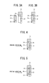
- FIG. 3 shows the detail of such a housing
- FIG. 3A shows a condition before the seal main body 14 is housed in the seal main body housing 21
- FIG. 3B shows a condition in which the seal main body 14 is housed in the seal main body housing 21.
- the gate burr housing 25 for housing the elastic-material gate burr 24 of the seal main body 14 is continuously provided with the seal main body housing 21 of the holder 13.
- the elastic-material gate burr 24 of the seal main body 14 is automatically housed in the gate burr housing 25. Accordingly, the labor work for completely cutting or eliminating the elastic-material gate burr 24 can be made unnecessary, while at the same time, the assembling workability is improved.
- each side seal includes the seal main body 14 which is formed by shaping the elastic material using a mold and which slide in contact with the guide rail 1, and the holder 13 for housing and holding the seal main body 14.
- the gate burr housing 25 for housing therein the elastic-material gate burr 24 of the seal main body 14 is formed in the seal main body housing 21 of the holder 13. Accordingly, it becomes unnecessary to completely cut or eliminate the elastic-material gate burr 24 of the seal main body 14, and the labor work can be reduced by what corresponds to such unnecessity. Moreover, the workability is also improved since it is fine if the elastic-material gate burr 24 of the seal main body 14 is just put in the gate burr housing 25 of the seal main body housing 21 of the holder 13.
- the seal main body 14 housed in the seal main body housing 21 of the holder 13 is covered by the cover 15, and thus the side seal 8 can be made as an assembly. This facilitates the handing at the time of assembling, and improves the assembling precision.
- FIG. 4 shows the detail of a side seal of a linear guide according to a second embodiment of the present invention.
- FIG. 4 shows a condition in which a seal main body 14 is housed in a seal main body housing 21.
- the linear guide according to the present embodiment has a general structure that is same as that of the first embodiment shown in FIG. 1 , and thus the detailed explanation thereof will be omitted.
- the side guide according to the present embodiment has a general structure that is same as that of the second embodiment shown in FIG. 2 , and thus the detailed explanation thereof will be omitted.
- the seal main body 14 is housed in the seal main body housing 21 of a holder 13, but at that time, when it is presumed that a forward side of a direction in which the seal main body 14 is held in the holder 13 (indicated by an arrow in FIG. 4 ) is a rear side and a backward side of the direction in which the seal main body is held is a front side, a gate burr housing 25 of the holder 13 is formed at the front side of the seal main body housing 21, and an elastic-material gate burr 24 of the seal main body 14 is formed at a portion corresponding to the gate burr housing 25, i.e., at the front side of the direction in which the seal main body 14 is housed..
- the contour in the horizontal direction is symmetrical as shown in FIG. 2 , and the front and rear faces of the seal main body 14 are distinguished such as the orientation of a lip 23, if the seal main body is assembled with a false orientation of the front and rear sides, i.e., falsely assembled, the seal main body 14 cannot fully accomplish its function in some cases..
- a gate burr housing 25 is formed at the front side of the seal main body housing 21 of the holder 13 and an elastic-material gate burr 24 of the seal main body 14 is formed at a corresponding portion to the gate burr housing 25, i.e., at the front side of the seal main body 14 in the direction in which the seal main body is housed like the present embodiment, a possibility that the seal main body 14 is assembled with a false orientation of the front and rear sides, i.e., the possibility of a false assembling can be reduced, thereby improving the assembling performance.
- the side seal of the linear guide of this embodiment when it is presumed that a forward side of a direction in which the seal main body 14 is held in the holder 13 is a rear side and a backward side of the direction in which the seal main body is held is a front side, if the gate burr housing 25 is formed at the front side of the seal main body housing 21 of the holder 13 and the elastic-material gate burr 24 of the seal main body 14 is formed at a corresponding portion to the gate burr housing 25, the elastic-material gate burr 24 can be used to distinguish the orientation of the seal main body 14 such as the front and rear sides and to prevent a false assembling, thereby improving the assembling performance.
- FIG. 5 shows the detail of a side seal of a linear guide according to a third embodiment of the present invention
- FIG.. 5 shows a condition in which a seal main body 14 is housed in a seal main body housing 21 such as FIG.. 3B according to the first embodiment.
- the linear guide according to the present embodiment has a general structure that is same as that of the first embodiment shown in FIG. 1 , and thus the detailed explanation thereof will be omitted.
- the side guide according to this embodiment has a general structure that is same as that of the second embodiment shown in FIG.. 2 , and thus the detailed explanation thereof will be omitted.
- the seal main body 14 is housed in the seal main body housing 21 of a holder 13, and at that time, when it is presumed that a forward side of a direction in which the seal main body 14 is held in the holder 13 (indicated by an arrow in FIG. 5 ) is a rear side and a backward side of the direction in which the seal main body is held is a front side, a gate burr housing 25 is formed at the rear side of the seal main body housing 21 of the holder 13, and an elastic-material gate burr 24 of the seal main body 14 is formed at a corresponding portion to the gate burr housing 25, i.e., the rear side of the seal main body 14 in the direction in which the seal main body is housed.
- the front and rear faces of the seal main body 14 are distinguished such as an orientation of a lip 23, if the seal main body is assembled with a false orientation of the front and rear sides, i.e., falsely assembled, the seal main body 14 cannot fully accomplish its function.
- a gate burr housing 25 is formed at the rear side of the seal main body housing 21 of the holder 13 and an elastic-material gate burr 24 of the seal main body 14 is formed at a corresponding portion to the gate burr housing 25, i.e., at the rear side of the seal main body 14 in which the seal main body is housed, the possibility that the seal main body 14 is assembled with a false orientation of the front and rear sides, i.e., the possibility of false assembling can be reduced, thereby improving the assembling performance.
- the elastic-material gate burr 24 of the seal main body 14 is pushed in and housed in the gate burr housing 25 formed at the rear side of the seal main body housing 21.
- the elastic-material gate burr 24 is engaged with the step difference at the front side of the gate burr housing 25 in which the seal main body is housed and serves as a stopper.
- the gate burr housing 25 is formed at a rear side of the seal main body housing 21 of the holder 13 and the elastic-material gate burr 24 of the seal main body 14 is formed at a corresponding portion to the gate burr housing 25, the elastic-material gate burr 24 can be used to distinguish the orientation of the seal main body 14 such as the front and rear sides and to prevent false assembling Therefore, this improves the assembling performance, while at the same time, preventing the seal main body 14 from being dropped off from the holder 13.
- the forms of the seal main body, the holder, and the cover are not limited to the ones explained in the above embodiments, and the present invention is applicable to the side seal of the linear guide in any forms.
Landscapes
- Engineering & Computer Science (AREA)
- General Engineering & Computer Science (AREA)
- Mechanical Engineering (AREA)
- Bearings For Parts Moving Linearly (AREA)
- Sealing Of Bearings (AREA)
Abstract
Description
- The present invention relates to side seals for linear guides, and more specifically to side seals attached to both ends in the sliding direction of a slider that slides along a guide rail, and in contact with the guide rail to prevent entrance of foreign materials such as refuses.
- Side seals to be attached to the slider of a linear guide have a structure such that a seal main body formed of an elastic material such as elastomer is sandwiched between a holder and a cover as disclosed in, for example, the following Patent Document 1. According to such a structure, the soft seal main body is held between the hard holder and cover so that an assembly can be made. This facilitates handling of such an assembly at the time of assembling and improves the assembling precision.
- Patent Literature 1:
JP 2007-211900 A - When the elastic material such as elastomer is shaped by pouring such an elastic material in a mold through injection molding or casting, a gate burr that is a sprue gate of the elastic material is formed. However, it takes a large amount of labor work to completely cut or eliminate the gate burr so as to be made flat with a surface of the seal main body.
The present invention has been made in view of the above-explained technical issue, and it is an object of the present invention to provide a side seal of the linear guide which needs no complete cutting or elimination of the gate burr of a seal main body and which is good at assembling performance. - To achieve the above object, there is provided a side seal of a linear guide attached to each of both ends of a slider of the linear guide in a sliding direction of the slider and sliding in contact with a guide rail, the side seal comprising: a seal main body formed by shaping an elastic material using a mold, and sliding in contact with the guide rail; and a holder for housing and holding the seal main body, a gate burr housing for housing an elastic-material gate burr of the seal main body being formed in a seal main body housing of the holder.
- Moreover, when it is presumed that a forward side of a direction in which the seal main body is held in the holder is a rear side and a backward side of the direction in which the seal main body is held is a front side, the gate burr housing may be formed at a front side of the seal main body housing of the holder, and the elastic-material gate burr of the seal main body may be formed at a corresponding portion to the gate burr housing.
In addition, when it is presumed that a forward side of a direction in which the seal main body is held in the holder is a rear side and a backward side of the direction in which the seal main body is held is a front side, the gate burr housing may be formed at a rear side of the seal main body housing of the holder and the elastic-material gate burr of the seal main body may be formed at a corresponding portion to the gate burr housing.
Moreover, a cover may cover the seal main body housed in the seal main body housing of the holder. - The side seal of the linear guide according to an embodiment of the present invention is attached to each of both ends of a slider of the linear guide in a sliding direction of the slider and sliding in contact with a guide rail, the side seal comprising: a seal main body formed by shaping an elastic material using a mold, and sliding in contact with the guide rail; and a holder for housing and holding the seal main body, a gate burr housing for housing an elastic-material gate burr of the seal main body being formed in a seal main body housing of the holder. According to such a structure, it becomes unnecessary to completely cut or eliminate the elastic-material gate burr of the seal main body. Accordingly, the labor work can be reduced by what corresponds to such unnecessity, and the elastic-material gate burr of the seal main body can be simply housed in the gate burr housing of the seal main body housing of the holder, thereby improving the workability.
- Moreover, when it is presumed that a forward side of a direction in which the seal main body is held in the holder is a rear side and a backward side of the direction in which the seal main body is held is a front side, the gate burr housing may be formed at a front side of the seal main body housing of the holder, and the elastic-material gate burr of the seal main body may be formed at a corresponding portion to the gate burr housing. According to such a structure, the elastic-material gate burr can be used to distinguish the orientation of the seal main body such as the front and rear sides and to prevent a false assembling, thereby improving the assembling performance
- Furthermore, when it is presumed that a forward side of a direction in which the seal main body is held in the holder is a rear side and a backward side of the direction in which the seal main body is held is a front side, the gate burr housing may be formed at a rear side of the seal main body housing of the holder and the elastic-material gate burr of the seal main body may be formed at a corresponding portion to the gate burr housing According to such a structure, the elastic-material gate burr can be used to distinguish the orientation of the seal main body such as the front and rear sides and to present a false assembling, thereby improving the assembling performance, while at the same time, preventing the seal main body from being dropped off from the holder.
- Still further, the side seal of the linear guide may further include a cover for covering the seal main body housed in the seal main body housing of the holder According to such a structure, the side seal can be made as an assembly, which facilitates the handling at the time of assembling and improves the assembling precision.
-
-
FIG. 1 is an overall perspective view of a linear guide showing side seals for the linear guide according to a first embodiment; -
FIG. 2 is a perspective view showing the detail of a side seal of the linear guide shown inFIG. 1 ; -
FIG. 3A and 3B are each a vertical cross-sectional view of the side seal shown inFIG. 2 ; -
FIG.. 4 is a vertical cross-sectional view showing a side seal of the linear guide according to a second embodiment; and -
FIG. 5 is a vertical cross-sectional view showing a side seal of the linear guide according to a third embodiment. - Next, an explanation will be given of a side seal of a linear guide according to a first embodiment with reference to the accompanying drawings.
FIG. 1 is a perspective view showing an overall structure of a linear guide using a side seal according to the present embodiment. The linear guide includes: a lengthened guide rail 1 having a substantially rectangular cross section; and aslider 2 which is mounted and provided on the guide rail 1 in a slidable manner in the lengthwise direction of the guide rail and which has a substantially letter U-shaped lateral cross section. The guide rail 1 hasball guiding grooves 3a which are formed of two inclined surfaces formed in the lengthwise direction of the guide rail to be adjacent to each other and having a substantially triangular cross section and which are formed in each side face of the guide rail orthogonal to the lengthwise direction. The guide rail 1 also has a plurality ofattachment openings 12 opened at atop face 1f of the guide rail and formed along the lengthwise direction. Each attachment opening 12 has: a counterbore opened at thetop face 1f of the guide rail 1; and a through-hole formed coaxially with the counterbore and penetrating through the guide rail 1 to reach the bottom face thereof. A washer-faced bolt is inserted in this attachment opening 12, and is engaged and tightened with an attaching object, thereby securing the guide rail 1 to the attaching object. - As explained above, the guide rail 1 has the
ball guiding grooves 3a formed in both side faces of the guide rail in the lengthwise direction thereof, and theslider 2 hasball guiding grooves 3b facing with respectiveball guiding grooves 3a of the guide rail 1 and formed in respective internal side faces of the slider. A plurality ofballs 4 that are rolling elements are rollably loaded between eachball guiding groove 3a and eachball guiding groove 3b. Moreover, theslider 2 has through-holes 5 which are substantially parallel with respectiveball guiding grooves 3b and which allow theballs 4 to pass through. To guide theballs 4 between the through-hole 5 and theball guiding groove 3b, areturn guide 6 and an end cap 7 are attached to each of ends of theslider 2 in the sliding direction (indicated by an arrow inFIG. 1 ). - Furthermore, each end cap 7 is attached with a
side seal 8 at the end in the sliding direction. Theside seal 8 is in contact with thetop face 1f of the guide rail 1 and theball guiding grooves 3a thereof, thereby preventing foreign materials such as refuses sticking to those top face and ball guiding grooves from entering into theslider 2.FIG. 2 shows a specific structure of theside seal 8. Theside seal 8 includes: aholder 13 attached to the end cap 7 by bolts 10 (seeFIG. 1 ) ; a sealmain body 14 housed in a sealmain body housing 21 formed in theholder 13; and acover 15 which covers the sealmain body 14 housed in the sealmain body housing 21 and which is secured theholder 13 by unillustrated - The
holder 13 is formed of a relatively thin metal plate in a substantially rectangular shape, and has a cut outportion 22 which is formed in the lower center part shown in the figure and which permits thetop face 1f of the guide rail 1 and theball guiding grooves 3a thereof to pass through with a predetermined clearance. The periphery of the cut outportion 22 is recessed to form the sealmain body housing 21 for housing therein the sealmain body 14. - The seal
main body 14 is formed in a shape corresponding to the periphery of the cut outportion 22, and has alip 23 formed in the internal side face to slide in tight contact with thetop face 1f of the guide rail 1 and theball guiding grooves 3a thereof. The sealmain body 14 is formed by pouring an elastic material such as elastomer in a mold by injection molding or casting, and has an elastic-material gate burr 24 which is the sprue of the elastic material and which is formed in the upper center part shown inFIG 2 . The sealmain body housing 14 of theholder 13 is continuously provided with agate burr housing 25 for housing therein the elastic-material gate burr 24, but the detail of such a gate burr housing will be discussed later. - The
cover 15 is formed of a thin synthesized resin plate in a substantially rectangular shape, and has a cut outportion 22 such as theholder 13 which is formed in the lower center part shown in the figure and which permits thetop face 1f of the guide rail 1 and theball guiding grooves 3a thereof to pass through with a predetermined clearance. The upper center of thecover 15 shown is also cut in a letter U-shape, but it is to allow a grease supply opening, not illustrated, to be attached with the end cap 7 thorough theholder 13. - As explained above, the seal
main body housing 21 of theholder 13 according to the present embodiment is continuously provided with thegate burr housing 25 for housing therein the elastic-material gate burr 24 of the sealmain body 14.FIG. 3 shows the detail of such a housingFIG. 3A shows a condition before the sealmain body 14 is housed in the sealmain body housing 21, andFIG. 3B shows a condition in which the sealmain body 14 is housed in the sealmain body housing 21. It takes a large amount of labor work to completely cut or eliminate the elastic-material gate burr 24 formed with the thin component or the small component such as the sealmain body 14 according to the present embodiment so as to form a so-called flat plane.. Hence, according to the present embodiment, as shown inFIG.. 3A , thegate burr housing 25 for housing the elastic-material gate burr 24 of the sealmain body 14 is continuously provided with the sealmain body housing 21 of theholder 13. As shown inFIG. 3B , when the sealmain body 14 is housed in the sealmain body housing 21 of theholder 13, the elastic-material gate burr 24 of the sealmain body 14 is automatically housed in thegate burr housing 25. Accordingly, the labor work for completely cutting or eliminating the elastic-material gate burr 24 can be made unnecessary, while at the same time, the assembling workability is improved. - As explained above, according to the side seal of the linear guide according to the present embodiment, the side seals 8 which slides in contact with the guide rail 1 are respectively attached to both ends of the
slider 2 of the linear guide in the sliding direction, Each side seal includes the sealmain body 14 which is formed by shaping the elastic material using a mold and which slide in contact with the guide rail 1, and theholder 13 for housing and holding the sealmain body 14. Thegate burr housing 25 for housing therein the elastic-material gate burr 24 of the sealmain body 14 is formed in the sealmain body housing 21 of theholder 13. Accordingly, it becomes unnecessary to completely cut or eliminate the elastic-material gate burr 24 of the sealmain body 14, and the labor work can be reduced by what corresponds to such unnecessity. Moreover, the workability is also improved since it is fine if the elastic-material gate burr 24 of the sealmain body 14 is just put in thegate burr housing 25 of the sealmain body housing 21 of theholder 13. - Moreover, the seal
main body 14 housed in the sealmain body housing 21 of theholder 13 is covered by thecover 15, and thus theside seal 8 can be made as an assembly. This facilitates the handing at the time of assembling, and improves the assembling precision. -
FIG. 4 shows the detail of a side seal of a linear guide according to a second embodiment of the present invention. LikeFIG. 3B of the first embodiment,FIG. 4 shows a condition in which a sealmain body 14 is housed in a sealmain body housing 21. The linear guide according to the present embodiment has a general structure that is same as that of the first embodiment shown inFIG. 1 , and thus the detailed explanation thereof will be omitted. Moreover, the side guide according to the present embodiment has a general structure that is same as that of the second embodiment shown inFIG. 2 , and thus the detailed explanation thereof will be omitted. - According to the present embodiment, also, the seal
main body 14 is housed in the sealmain body housing 21 of aholder 13, but at that time, when it is presumed that a forward side of a direction in which the sealmain body 14 is held in the holder 13 (indicated by an arrow inFIG. 4 ) is a rear side and a backward side of the direction in which the seal main body is held is a front side, agate burr housing 25 of theholder 13 is formed at the front side of the sealmain body housing 21, and an elastic-material gate burr 24 of the sealmain body 14 is formed at a portion corresponding to thegate burr housing 25, i.e., at the front side of the direction in which the sealmain body 14 is housed.. - When, for example, such as the seal
main body 14 according to the present embodiment, the contour in the horizontal direction is symmetrical as shown inFIG. 2 , and the front and rear faces of the sealmain body 14 are distinguished such as the orientation of alip 23, if the seal main body is assembled with a false orientation of the front and rear sides, i.e., falsely assembled, the sealmain body 14 cannot fully accomplish its function in some cases.. When, for example, agate burr housing 25 is formed at the front side of the sealmain body housing 21 of theholder 13 and an elastic-material gate burr 24 of the sealmain body 14 is formed at a corresponding portion to thegate burr housing 25, i.e., at the front side of the sealmain body 14 in the direction in which the seal main body is housed like the present embodiment, a possibility that the sealmain body 14 is assembled with a false orientation of the front and rear sides, i.e., the possibility of a false assembling can be reduced, thereby improving the assembling performance. - As explained above, according to the side seal of the linear guide of this embodiment, when it is presumed that a forward side of a direction in which the seal
main body 14 is held in theholder 13 is a rear side and a backward side of the direction in which the seal main body is held is a front side, if thegate burr housing 25 is formed at the front side of the sealmain body housing 21 of theholder 13 and the elastic-material gate burr 24 of the sealmain body 14 is formed at a corresponding portion to thegate burr housing 25, the elastic-material gate burr 24 can be used to distinguish the orientation of the sealmain body 14 such as the front and rear sides and to prevent a false assembling, thereby improving the assembling performance. -
FIG. 5 shows the detail of a side seal of a linear guide according to a third embodiment of the present inventionFIG.. 5 shows a condition in which a sealmain body 14 is housed in a sealmain body housing 21 such asFIG.. 3B according to the first embodiment. The linear guide according to the present embodiment has a general structure that is same as that of the first embodiment shown inFIG. 1 , and thus the detailed explanation thereof will be omitted. Moreover, the side guide according to this embodiment has a general structure that is same as that of the second embodiment shown inFIG.. 2 , and thus the detailed explanation thereof will be omitted. - According to the present embodiment, also, the seal
main body 14 is housed in the sealmain body housing 21 of aholder 13, and at that time, when it is presumed that a forward side of a direction in which the sealmain body 14 is held in the holder 13 (indicated by an arrow inFIG. 5 ) is a rear side and a backward side of the direction in which the seal main body is held is a front side, agate burr housing 25 is formed at the rear side of the sealmain body housing 21 of theholder 13, and an elastic-material gate burr 24 of the sealmain body 14 is formed at a corresponding portion to thegate burr housing 25, i.e., the rear side of the sealmain body 14 in the direction in which the seal main body is housed. - According to the present embodiment, when, such as the second embodiment, the front and rear faces of the seal
main body 14 are distinguished such as an orientation of alip 23, if the seal main body is assembled with a false orientation of the front and rear sides, i.e., falsely assembled, the sealmain body 14 cannot fully accomplish its function. When, for example, agate burr housing 25 is formed at the rear side of the sealmain body housing 21 of theholder 13 and an elastic-material gate burr 24 of the sealmain body 14 is formed at a corresponding portion to thegate burr housing 25, i.e., at the rear side of the sealmain body 14 in which the seal main body is housed, the possibility that the sealmain body 14 is assembled with a false orientation of the front and rear sides, i.e., the possibility of false assembling can be reduced, thereby improving the assembling performance. - Moreover, according to the present embodiment, the elastic-
material gate burr 24 of the sealmain body 14 is pushed in and housed in thegate burr housing 25 formed at the rear side of the sealmain body housing 21. Thus, the elastic-material gate burr 24 is engaged with the step difference at the front side of thegate burr housing 25 in which the seal main body is housed and serves as a stopper. Hence, it becomes possible to prevent the sealmain body 14 from being dropped off from theholder 13. - As explained above, according to the side seal of the linear guide according to the present embodiment, when it is presumed that a forward side of a direction in which the seal
main body 14 is held in theholder 13 is a rear side and a backward side of the direction in which the seal main body is retained is a front side, thegate burr housing 25 is formed at a rear side of the sealmain body housing 21 of theholder 13 and the elastic-material gate burr 24 of the sealmain body 14 is formed at a corresponding portion to thegate burr housing 25, the elastic-material gate burr 24 can be used to distinguish the orientation of the sealmain body 14 such as the front and rear sides and to prevent false assembling Therefore, this improves the assembling performance, while at the same time, preventing the sealmain body 14 from being dropped off from theholder 13.
The forms of the seal main body, the holder, and the cover are not limited to the ones explained in the above embodiments, and the present invention is applicable to the side seal of the linear guide in any forms. -
1 Guide rail 2 Slider 3a, 3b Ball guiding groove 4 Ball 5 Through- hole 6 Return guide 7 End cap 8 Side seal 10 Bolt 12 Attachment opening 13 Holder 14 Seal main body 15 Cover 21 Seal main body housing 22 Cut section 23 Lip 24 Elastic- material gate burr 25 Gate burr housing
Claims (4)
- A side seal of a lineal guide attached to each of both ends of a slider of the linear guide in a sliding direction of the slider and sliding in contact with a guide rail, the side seal comprising:a seal main body formed by shaping an elastic material using a mold, and sliding in contact with the guide rail; anda holder for housing and holding the seal main body,a gate burr housing for housing an elastic-material gate burr of the seal main body being formed in a seal main body housing of the holder.
- The side seal of the linear guide according to claim 1, wherein when it is presumed that a forward side of a direction in which the seal main body is held in the holder is a rear side and a backward side of the direction in which the seal main body is held is a front side, the gate burr housing is formed at a front side of the seal main body housing of the holder, and the elastic-material gate burr of the seal main body is formed at a corresponding portion to the gate burr housing.
- The side seal of the linear guide according to claim 1, wherein when it is presumed that a forward side of a direction in which the seal main body is held in the holder is a rear side and a backward side of the direction in which the seal main body is held is a front side, the gate burr housing is formed at a rear side of the seal main body housing of the holder and the elastic-material gate burr of the seal main body is formed at a corresponding portion to the gate burr housing.
- The side seal of the linear guide according to claim 2 or 3, further comprising a cover for covering the seal main body housed in the seal main body housing of the holder.
Applications Claiming Priority (2)
| Application Number | Priority Date | Filing Date | Title |
|---|---|---|---|
| JP2010183969A JP5668362B2 (en) | 2010-08-19 | 2010-08-19 | Linear guide side seal |
| PCT/JP2011/004185 WO2012023238A1 (en) | 2010-08-19 | 2011-07-25 | Side seal for linear guide |
Publications (3)
| Publication Number | Publication Date |
|---|---|
| EP2607729A1 true EP2607729A1 (en) | 2013-06-26 |
| EP2607729A4 EP2607729A4 (en) | 2016-11-09 |
| EP2607729B1 EP2607729B1 (en) | 2019-03-13 |
Family
ID=45604909
Family Applications (1)
| Application Number | Title | Priority Date | Filing Date |
|---|---|---|---|
| EP11817889.6A Active EP2607729B1 (en) | 2010-08-19 | 2011-07-25 | Side seal for linear guide |
Country Status (5)
| Country | Link |
|---|---|
| US (1) | US8814431B2 (en) |
| EP (1) | EP2607729B1 (en) |
| JP (1) | JP5668362B2 (en) |
| CN (1) | CN102549280B (en) |
| WO (1) | WO2012023238A1 (en) |
Families Citing this family (3)
| Publication number | Priority date | Publication date | Assignee | Title |
|---|---|---|---|---|
| DE102012205003B4 (en) * | 2012-03-28 | 2015-04-09 | Aktiebolaget Skf | Sealing plate for a profile rail car, assembly product and profile rail car |
| JP5783322B2 (en) | 2012-10-23 | 2015-09-24 | 日本精工株式会社 | Linear motion guide device |
| CN112994317B (en) * | 2021-02-05 | 2022-03-15 | 浙江得利亚自动化制造有限公司 | Dustproof high-speed low-noise HR linear sliding block |
Family Cites Families (10)
| Publication number | Priority date | Publication date | Assignee | Title |
|---|---|---|---|---|
| JP2526061Y2 (en) * | 1990-06-20 | 1997-02-12 | 日本精工株式会社 | Dust proof device for linear guide device |
| DE10126439A1 (en) * | 2001-05-31 | 2002-12-05 | Ina Schaeffler Kg | Linear roller bearing element |
| JP4306423B2 (en) * | 2003-11-25 | 2009-08-05 | 豊田合成株式会社 | Fuel cap |
| EP1512572B1 (en) | 2003-09-05 | 2009-12-30 | Toyoda Gosei Co., Ltd. | Cap device |
| JP2007211900A (en) | 2006-02-09 | 2007-08-23 | Nsk Ltd | End seal and linear motion guide device including the same |
| CN101042160B (en) * | 2006-03-20 | 2010-10-06 | 直得科技股份有限公司 | Linear slide |
| JP2007309364A (en) * | 2006-05-16 | 2007-11-29 | Nsk Ltd | Seal for linear motion guide device and linear motion guide device |
| JP4830662B2 (en) | 2006-06-22 | 2011-12-07 | 住友電装株式会社 | Plastic molded product with metal plate |
| JP2008151325A (en) * | 2006-12-20 | 2008-07-03 | Nsk Ltd | Linear motion guide device |
| DE102008053932A1 (en) * | 2008-10-30 | 2010-05-06 | Schaeffler Kg | linear bearings |
-
2010
- 2010-08-19 JP JP2010183969A patent/JP5668362B2/en active Active
-
2011
- 2011-07-25 US US13/817,288 patent/US8814431B2/en active Active
- 2011-07-25 EP EP11817889.6A patent/EP2607729B1/en active Active
- 2011-07-25 WO PCT/JP2011/004185 patent/WO2012023238A1/en not_active Ceased
- 2011-07-25 CN CN201180001224.9A patent/CN102549280B/en active Active
Also Published As
| Publication number | Publication date |
|---|---|
| EP2607729A4 (en) | 2016-11-09 |
| EP2607729B1 (en) | 2019-03-13 |
| CN102549280B (en) | 2015-04-15 |
| US8814431B2 (en) | 2014-08-26 |
| US20130142459A1 (en) | 2013-06-06 |
| JP2012041987A (en) | 2012-03-01 |
| CN102549280A (en) | 2012-07-04 |
| JP5668362B2 (en) | 2015-02-12 |
| WO2012023238A1 (en) | 2012-02-23 |
Similar Documents
| Publication | Publication Date | Title |
|---|---|---|
| US5087130A (en) | Under seal device of linear movement guide bearing | |
| EP1245845A1 (en) | Linear motion guide unit | |
| US20080089622A1 (en) | Linear guide device | |
| US8814431B2 (en) | Side seal of linear guide | |
| JPH08247146A (en) | Top cover, track rail unit and guide unit equipped with the same | |
| EP2388488A1 (en) | Linear guide device | |
| US6766897B2 (en) | Linear motion guide unit | |
| CN107407328A (en) | linear motion guidance device | |
| US9863470B2 (en) | Motion guide apparatus and method for manufacturing the same | |
| US5358336A (en) | Linear motion rolling guide unit | |
| CN106523524B (en) | Linear sliding device with comprehensive dust prevention function | |
| JP5672895B2 (en) | Attachment for temporary shaft of linear motion guide device | |
| US9777768B2 (en) | Movement device | |
| US20130223770A1 (en) | Seal Device and Linear Guide Device | |
| US5324116A (en) | Linear motion rolling guide unit | |
| JPH0359284B2 (en) | ||
| JP2011012715A (en) | Linear motion guide unit | |
| CN217055984U (en) | Steel ball retainer of sliding block for linear guide rail | |
| CN213419684U (en) | Retainer structure on sliding seat | |
| CN213451350U (en) | Seamless Rolling Element Circulation Path Dust System | |
| EP4717939A1 (en) | Linear transmission module | |
| US20250325074A1 (en) | Cover member and linear motion guide unit | |
| US9133878B2 (en) | Seal mechanism of linear guide apparatus | |
| TWI504820B (en) | Side seals and linear guide devices with side seals | |
| JP2003239959A (en) | Linear motion guide device |
Legal Events
| Date | Code | Title | Description |
|---|---|---|---|
| PUAI | Public reference made under article 153(3) epc to a published international application that has entered the european phase |
Free format text: ORIGINAL CODE: 0009012 |
|
| 17P | Request for examination filed |
Effective date: 20130220 |
|
| AK | Designated contracting states |
Kind code of ref document: A1 Designated state(s): AL AT BE BG CH CY CZ DE DK EE ES FI FR GB GR HR HU IE IS IT LI LT LU LV MC MK MT NL NO PL PT RO RS SE SI SK SM TR |
|
| DAX | Request for extension of the european patent (deleted) | ||
| RA4 | Supplementary search report drawn up and despatched (corrected) |
Effective date: 20161010 |
|
| RIC1 | Information provided on ipc code assigned before grant |
Ipc: F16C 29/06 20060101AFI20161004BHEP Ipc: F16C 29/08 20060101ALI20161004BHEP |
|
| GRAP | Despatch of communication of intention to grant a patent |
Free format text: ORIGINAL CODE: EPIDOSNIGR1 |
|
| STAA | Information on the status of an ep patent application or granted ep patent |
Free format text: STATUS: GRANT OF PATENT IS INTENDED |
|
| INTG | Intention to grant announced |
Effective date: 20180928 |
|
| GRAS | Grant fee paid |
Free format text: ORIGINAL CODE: EPIDOSNIGR3 |
|
| GRAA | (expected) grant |
Free format text: ORIGINAL CODE: 0009210 |
|
| STAA | Information on the status of an ep patent application or granted ep patent |
Free format text: STATUS: THE PATENT HAS BEEN GRANTED |
|
| AK | Designated contracting states |
Kind code of ref document: B1 Designated state(s): AL AT BE BG CH CY CZ DE DK EE ES FI FR GB GR HR HU IE IS IT LI LT LU LV MC MK MT NL NO PL PT RO RS SE SI SK SM TR |
|
| REG | Reference to a national code |
Ref country code: GB Ref legal event code: FG4D |
|
| REG | Reference to a national code |
Ref country code: CH Ref legal event code: EP Ref country code: AT Ref legal event code: REF Ref document number: 1108097 Country of ref document: AT Kind code of ref document: T Effective date: 20190315 |
|
| REG | Reference to a national code |
Ref country code: DE Ref legal event code: R096 Ref document number: 602011057185 Country of ref document: DE |
|
| REG | Reference to a national code |
Ref country code: IE Ref legal event code: FG4D |
|
| REG | Reference to a national code |
Ref country code: DE Ref legal event code: R082 Ref document number: 602011057185 Country of ref document: DE |
|
| REG | Reference to a national code |
Ref country code: NL Ref legal event code: MP Effective date: 20190313 |
|
| REG | Reference to a national code |
Ref country code: LT Ref legal event code: MG4D |
|
| PG25 | Lapsed in a contracting state [announced via postgrant information from national office to epo] |
Ref country code: SE Free format text: LAPSE BECAUSE OF FAILURE TO SUBMIT A TRANSLATION OF THE DESCRIPTION OR TO PAY THE FEE WITHIN THE PRESCRIBED TIME-LIMIT Effective date: 20190313 Ref country code: NO Free format text: LAPSE BECAUSE OF FAILURE TO SUBMIT A TRANSLATION OF THE DESCRIPTION OR TO PAY THE FEE WITHIN THE PRESCRIBED TIME-LIMIT Effective date: 20190613 Ref country code: FI Free format text: LAPSE BECAUSE OF FAILURE TO SUBMIT A TRANSLATION OF THE DESCRIPTION OR TO PAY THE FEE WITHIN THE PRESCRIBED TIME-LIMIT Effective date: 20190313 Ref country code: LT Free format text: LAPSE BECAUSE OF FAILURE TO SUBMIT A TRANSLATION OF THE DESCRIPTION OR TO PAY THE FEE WITHIN THE PRESCRIBED TIME-LIMIT Effective date: 20190313 |
|
| PG25 | Lapsed in a contracting state [announced via postgrant information from national office to epo] |
Ref country code: GR Free format text: LAPSE BECAUSE OF FAILURE TO SUBMIT A TRANSLATION OF THE DESCRIPTION OR TO PAY THE FEE WITHIN THE PRESCRIBED TIME-LIMIT Effective date: 20190614 Ref country code: BG Free format text: LAPSE BECAUSE OF FAILURE TO SUBMIT A TRANSLATION OF THE DESCRIPTION OR TO PAY THE FEE WITHIN THE PRESCRIBED TIME-LIMIT Effective date: 20190613 Ref country code: NL Free format text: LAPSE BECAUSE OF FAILURE TO SUBMIT A TRANSLATION OF THE DESCRIPTION OR TO PAY THE FEE WITHIN THE PRESCRIBED TIME-LIMIT Effective date: 20190313 Ref country code: RS Free format text: LAPSE BECAUSE OF FAILURE TO SUBMIT A TRANSLATION OF THE DESCRIPTION OR TO PAY THE FEE WITHIN THE PRESCRIBED TIME-LIMIT Effective date: 20190313 Ref country code: HR Free format text: LAPSE BECAUSE OF FAILURE TO SUBMIT A TRANSLATION OF THE DESCRIPTION OR TO PAY THE FEE WITHIN THE PRESCRIBED TIME-LIMIT Effective date: 20190313 Ref country code: LV Free format text: LAPSE BECAUSE OF FAILURE TO SUBMIT A TRANSLATION OF THE DESCRIPTION OR TO PAY THE FEE WITHIN THE PRESCRIBED TIME-LIMIT Effective date: 20190313 |
|
| REG | Reference to a national code |
Ref country code: AT Ref legal event code: MK05 Ref document number: 1108097 Country of ref document: AT Kind code of ref document: T Effective date: 20190313 |
|
| PG25 | Lapsed in a contracting state [announced via postgrant information from national office to epo] |
Ref country code: RO Free format text: LAPSE BECAUSE OF FAILURE TO SUBMIT A TRANSLATION OF THE DESCRIPTION OR TO PAY THE FEE WITHIN THE PRESCRIBED TIME-LIMIT Effective date: 20190313 Ref country code: SK Free format text: LAPSE BECAUSE OF FAILURE TO SUBMIT A TRANSLATION OF THE DESCRIPTION OR TO PAY THE FEE WITHIN THE PRESCRIBED TIME-LIMIT Effective date: 20190313 Ref country code: EE Free format text: LAPSE BECAUSE OF FAILURE TO SUBMIT A TRANSLATION OF THE DESCRIPTION OR TO PAY THE FEE WITHIN THE PRESCRIBED TIME-LIMIT Effective date: 20190313 Ref country code: ES Free format text: LAPSE BECAUSE OF FAILURE TO SUBMIT A TRANSLATION OF THE DESCRIPTION OR TO PAY THE FEE WITHIN THE PRESCRIBED TIME-LIMIT Effective date: 20190313 Ref country code: AL Free format text: LAPSE BECAUSE OF FAILURE TO SUBMIT A TRANSLATION OF THE DESCRIPTION OR TO PAY THE FEE WITHIN THE PRESCRIBED TIME-LIMIT Effective date: 20190313 Ref country code: PT Free format text: LAPSE BECAUSE OF FAILURE TO SUBMIT A TRANSLATION OF THE DESCRIPTION OR TO PAY THE FEE WITHIN THE PRESCRIBED TIME-LIMIT Effective date: 20190713 Ref country code: CZ Free format text: LAPSE BECAUSE OF FAILURE TO SUBMIT A TRANSLATION OF THE DESCRIPTION OR TO PAY THE FEE WITHIN THE PRESCRIBED TIME-LIMIT Effective date: 20190313 |
|
| PG25 | Lapsed in a contracting state [announced via postgrant information from national office to epo] |
Ref country code: SM Free format text: LAPSE BECAUSE OF FAILURE TO SUBMIT A TRANSLATION OF THE DESCRIPTION OR TO PAY THE FEE WITHIN THE PRESCRIBED TIME-LIMIT Effective date: 20190313 Ref country code: PL Free format text: LAPSE BECAUSE OF FAILURE TO SUBMIT A TRANSLATION OF THE DESCRIPTION OR TO PAY THE FEE WITHIN THE PRESCRIBED TIME-LIMIT Effective date: 20190313 |
|
| REG | Reference to a national code |
Ref country code: DE Ref legal event code: R097 Ref document number: 602011057185 Country of ref document: DE |
|
| PG25 | Lapsed in a contracting state [announced via postgrant information from national office to epo] |
Ref country code: AT Free format text: LAPSE BECAUSE OF FAILURE TO SUBMIT A TRANSLATION OF THE DESCRIPTION OR TO PAY THE FEE WITHIN THE PRESCRIBED TIME-LIMIT Effective date: 20190313 Ref country code: IS Free format text: LAPSE BECAUSE OF FAILURE TO SUBMIT A TRANSLATION OF THE DESCRIPTION OR TO PAY THE FEE WITHIN THE PRESCRIBED TIME-LIMIT Effective date: 20190713 |
|
| PLBE | No opposition filed within time limit |
Free format text: ORIGINAL CODE: 0009261 |
|
| STAA | Information on the status of an ep patent application or granted ep patent |
Free format text: STATUS: NO OPPOSITION FILED WITHIN TIME LIMIT |
|
| PG25 | Lapsed in a contracting state [announced via postgrant information from national office to epo] |
Ref country code: DK Free format text: LAPSE BECAUSE OF FAILURE TO SUBMIT A TRANSLATION OF THE DESCRIPTION OR TO PAY THE FEE WITHIN THE PRESCRIBED TIME-LIMIT Effective date: 20190313 |
|
| 26N | No opposition filed |
Effective date: 20191216 |
|
| PG25 | Lapsed in a contracting state [announced via postgrant information from national office to epo] |
Ref country code: MC Free format text: LAPSE BECAUSE OF FAILURE TO SUBMIT A TRANSLATION OF THE DESCRIPTION OR TO PAY THE FEE WITHIN THE PRESCRIBED TIME-LIMIT Effective date: 20190313 Ref country code: SI Free format text: LAPSE BECAUSE OF FAILURE TO SUBMIT A TRANSLATION OF THE DESCRIPTION OR TO PAY THE FEE WITHIN THE PRESCRIBED TIME-LIMIT Effective date: 20190313 |
|
| REG | Reference to a national code |
Ref country code: CH Ref legal event code: PL |
|
| GBPC | Gb: european patent ceased through non-payment of renewal fee |
Effective date: 20190725 |
|
| PG25 | Lapsed in a contracting state [announced via postgrant information from national office to epo] |
Ref country code: TR Free format text: LAPSE BECAUSE OF FAILURE TO SUBMIT A TRANSLATION OF THE DESCRIPTION OR TO PAY THE FEE WITHIN THE PRESCRIBED TIME-LIMIT Effective date: 20190313 |
|
| REG | Reference to a national code |
Ref country code: BE Ref legal event code: MM Effective date: 20190731 |
|
| PG25 | Lapsed in a contracting state [announced via postgrant information from national office to epo] |
Ref country code: GB Free format text: LAPSE BECAUSE OF NON-PAYMENT OF DUE FEES Effective date: 20190725 |
|
| PG25 | Lapsed in a contracting state [announced via postgrant information from national office to epo] |
Ref country code: LU Free format text: LAPSE BECAUSE OF NON-PAYMENT OF DUE FEES Effective date: 20190725 Ref country code: LI Free format text: LAPSE BECAUSE OF NON-PAYMENT OF DUE FEES Effective date: 20190731 Ref country code: CH Free format text: LAPSE BECAUSE OF NON-PAYMENT OF DUE FEES Effective date: 20190731 Ref country code: BE Free format text: LAPSE BECAUSE OF NON-PAYMENT OF DUE FEES Effective date: 20190731 |
|
| PG25 | Lapsed in a contracting state [announced via postgrant information from national office to epo] |
Ref country code: FR Free format text: LAPSE BECAUSE OF NON-PAYMENT OF DUE FEES Effective date: 20190731 |
|
| PG25 | Lapsed in a contracting state [announced via postgrant information from national office to epo] |
Ref country code: IE Free format text: LAPSE BECAUSE OF NON-PAYMENT OF DUE FEES Effective date: 20190725 |
|
| PG25 | Lapsed in a contracting state [announced via postgrant information from national office to epo] |
Ref country code: CY Free format text: LAPSE BECAUSE OF FAILURE TO SUBMIT A TRANSLATION OF THE DESCRIPTION OR TO PAY THE FEE WITHIN THE PRESCRIBED TIME-LIMIT Effective date: 20190313 |
|
| PG25 | Lapsed in a contracting state [announced via postgrant information from national office to epo] |
Ref country code: MT Free format text: LAPSE BECAUSE OF FAILURE TO SUBMIT A TRANSLATION OF THE DESCRIPTION OR TO PAY THE FEE WITHIN THE PRESCRIBED TIME-LIMIT Effective date: 20190313 Ref country code: HU Free format text: LAPSE BECAUSE OF FAILURE TO SUBMIT A TRANSLATION OF THE DESCRIPTION OR TO PAY THE FEE WITHIN THE PRESCRIBED TIME-LIMIT; INVALID AB INITIO Effective date: 20110725 |
|
| PG25 | Lapsed in a contracting state [announced via postgrant information from national office to epo] |
Ref country code: MK Free format text: LAPSE BECAUSE OF FAILURE TO SUBMIT A TRANSLATION OF THE DESCRIPTION OR TO PAY THE FEE WITHIN THE PRESCRIBED TIME-LIMIT Effective date: 20190313 |
|
| PGFP | Annual fee paid to national office [announced via postgrant information from national office to epo] |
Ref country code: DE Payment date: 20250528 Year of fee payment: 15 |
|
| PGFP | Annual fee paid to national office [announced via postgrant information from national office to epo] |
Ref country code: IT Payment date: 20250623 Year of fee payment: 15 |