EP2607719B1 - Blind fastener - Google Patents
Blind fastener Download PDFInfo
- Publication number
- EP2607719B1 EP2607719B1 EP11194566.3A EP11194566A EP2607719B1 EP 2607719 B1 EP2607719 B1 EP 2607719B1 EP 11194566 A EP11194566 A EP 11194566A EP 2607719 B1 EP2607719 B1 EP 2607719B1
- Authority
- EP
- European Patent Office
- Prior art keywords
- ring
- collar
- adapter
- blind
- spring
- Prior art date
- Legal status (The legal status is an assumption and is not a legal conclusion. Google has not performed a legal analysis and makes no representation as to the accuracy of the status listed.)
- Active
Links
Images






Classifications
-
- F—MECHANICAL ENGINEERING; LIGHTING; HEATING; WEAPONS; BLASTING
- F16—ENGINEERING ELEMENTS AND UNITS; GENERAL MEASURES FOR PRODUCING AND MAINTAINING EFFECTIVE FUNCTIONING OF MACHINES OR INSTALLATIONS; THERMAL INSULATION IN GENERAL
- F16B—DEVICES FOR FASTENING OR SECURING CONSTRUCTIONAL ELEMENTS OR MACHINE PARTS TOGETHER, e.g. NAILS, BOLTS, CIRCLIPS, CLAMPS, CLIPS OR WEDGES; JOINTS OR JOINTING
- F16B5/00—Joining sheets or plates, e.g. panels, to one another or to strips or bars parallel to them
- F16B5/02—Joining sheets or plates, e.g. panels, to one another or to strips or bars parallel to them by means of fastening members using screw-thread
Definitions
- This invention relates to a blind fastener and particularly to a blind fastener adapter for a conventional screw-threaded nut and screw.
- Blind fasteners are well known, and comprise devices insertable from one side through a hole in a member, and having means to anchor the device on the distal side of the hole.
- a screw-threaded component may be included, to tighten the device to the member.
- Such fasteners are utilised where access is available from one side only, and may for example clamp members together or be used to provide an anchorage.
- a blind fastener includes a proximal side screw-threaded component having a screw-threaded distal (or blind) side anchorage arranged for close fitting passage through a hole. Once through the hole, the distal side anchorage changes form so as to resist withdrawal thereof, whereupon the proximal side component is tightened to firmly attach the fastener.
- the distal side fastener may for example comprise a folding component which is adapted to pass through the hole in folded form, and open out on the distal side to a diameter larger than the hole.
- EP0175273 discloses an expanding anchor plug having a cap spring which retains cylindrical segments in relation to a conical expander.
- GB2477361 discloses a radially expandable connector assembly having a conical part and a number of part cylindrical members, which displace radially outwards as the conical part is displaced linearly.
- the part cylindrical members are biased inwardly to contact during an opposite linear action of the conical part.
- a blind fastener adapter for a conventional screw-threaded nut and screw, the adapter comprising a collar and a segmented ring over the collar, the ring and collar having a tapered interface wherein relative axial movement results in a change of diameter of said ring, said adapter further including a spring adapted to bias said collar and ring into mutual engagement, said collar and ring including means to prevent substantial relative angular movement thereof, said collar being adapted for engagement by a blind side head of said screw in use, and said ring being adapted for blind side engagement of the perimeter of a hole, characterised in that the spring is a coil compression spring that axially biases said collar and ring into mutual engagement in use.
- the blind side head may be a nut or the head of a male fastener, such as a machine screw or bolt.
- the screw may be a threaded stud, or the shank of a male fastener.
- a blind fastener adapter for a conventional screw-threaded screw, the adapter comprising a collar and a segmented ring over the collar, the ring and collar having a tapered interface wherein relative axial movement results in a change of diameter of said ring, said adapter further including a spring adapted to bias said collar and ring into mutual engagement, said collar and ring including means to prevent substantial relative angular movement thereof, said collar being threaded for engagement by a blind side thread of said screw in use, and said ring being adapted for blind side engagement of the perimeter of a hole, characterised in that the spring is a coil compression spring that axially biases said collar and ring into mutual engagement in use.
- the ring and collar are fixed against relative rotation by dogs; such dogs may for example comprise protrusions of one of the ring and collar, and mating recesses of the other of ring and collar.
- protruding rails of the collar extend in the direction of the axis of rotation thereof, and engage in close fitting grooves of the ring.
- the ring may have three segments, each segment being restrained by a suitable dog.
- each segment is retained against radial separation by the collar, for example by an enlarged head of a rail engageable in an undercut groove.
- Each segment may comprise an individually separable component retained solely by a suitable form-locking profile.
- the spring may bear directly on said ring in use, and sized to fit closely around said screw.
- the fastener may include a further coil compression spring outboard the aforesaid coil compression spring and of a diameter insufficient to pass through a hole for which the fastener is intended.
- a further spring provides frictional bias to provide anti-rotational force for said collar, in use.
- the adapter may further include a collared washer at the proximal side of said coil spring.
- a reduced diameter of said washer being sized to engage closely within the hole for which the fastener is intended, and the washer having an internal recess of sufficient depth to accept said spring when compressed. Such a recess avoids potential coil binding of the spring, which could affect proper tightening of the fastener.
- the ring has a reduced diameter portion at the proximal side so as to present a shoulder.
- the reduced diameter portion is also sized for close fitting engagement in the hole for which the fastener is intended, and the shoulder bears on the perimeter of the distal side of the hole in use.
- a blind fastener adapter has the advantage of being retro-fittable to a standard machine screw, for example a bolt. This means that special threaded components are not required, and that standard specification threads, with known material properties can be used. Standard machine screws are relatively inexpensive compared with special forms. Furthermore, standard fixing tools, such as socket spanners, may be used for both standard and blind fasteners. Moreover, a special supply of blind fasteners is unnecessary provided that a supply of suitable adapters is provided for those instances where a blind fastener is required.
- a fastener comprises a conventional hexagonal headed machine screw 11 having a corresponding hexagon nut 12 of the same size.
- an adapter Between the head of the machine screw and the nut the components of an adapter comprise in series, a tapered collar 13, a segmented ring 14, a coil compression spring 15 and a shouldered washer 16.
- the adapter renders the standard screw and nut suitable for blind (one-sided) installation, and may be filled to the machine screw and nut in either orientation, as illustrated in Figs. 1 and 2 , with the proviso that in use the fastener enters a corresponding hole collar first.
- the collar 13 comprises a plain diameter portion 21 for contact with the adjacent hexagon and a tapered portion 22 having three equi-spaced protruding rails 23.
- Each rail has an enlarged head 24 ( Fig. 6 ) of constant section.
- the rails 23 extend in the direction of the axis of the fastener, and the bore 25 of the collar allows free movement along the threads of the fastener.
- the ring comprises three identical and equi-spaced segments 31 each having an undercut recess 32 ( Fig. 6 ) for sliding engagement with the respective enlarged head 24.
- the internal surfaces of the segments 31 are arcuate and conical in form, so as to match the conical form of the collar 13.
- the proximal side of the segments is shouldered so that in use ring 14 fits closely in the distal side of a hole for which the fastener is intended.
- the spring 15 is a light wire coil compression spring, which in use biases the segments of the ring 14 towards the collar 13 (downwardly as viewed in Fig. 3 ).
- the shouldered washer 16 has a smaller diameter 41 adapted for close fitting engagement in the proximal side of a hole for which the fastener is intended.
- the internal diameter 42 is also relieved to accommodate the proximal end of the spring 15, and is of sufficient depth to accept the spring without coil binding. In other words the spring can be fully compressed and housed within the washer 16, for reasons which will become apparent.
- the components of the assembly are assembled in the manner indicated in Fig. 1 or Fig. 2 - the coil spring 15 lightly biases the ring 14 and collar 13 into engagement, and the ring 14 tends to adopt a position at the base of the taper of the collar 13, as illustrated in Figs. 1 and 2 .
- the outside diameter of the ring is greater than the plain portion 21 of the collar.
- the blind fastener assembly is offered up to a hole, collar first.
- a through hole of two plates 51, 52 is provided.
- the dimensions of the adapter and hexagons are selected so that the distal hexagon and collar 13 pass freely through the hole, but the ring 14 does not ( Fig. 4a ).
- Further light insertion pressure causes the spring 15 to collapse ( Fig. 4b ) as the collar and ring separate the segments 31 move radially inwardly in consequence of the form-locking profile of Fig. 6 .
- the taper is arranged so that the segments are drawn sufficiently inwardly to eventually pass through the hole ( Fig. 4c ) under pressure from the spring 15, whereupon the collar and ring become more closely engaged again, which in turn guides the segments to a radially outer condition in which the shouldered portion of the ring engages in the distal side of the hole ( Fig. 4d ).
- the proximal side hexagon may now be turned to tighten the fastener by hand, a slight proximal pull being sufficient to ensure frictional drag on the distal side hexagon.
- the drag force may be enhanced by suitable raised formations of the areas in contact, or alternatively the collar may be arranged to lightly grip the adjacent hexagon.
- hexagons are selected so as to pass through the hole, though it will be understood that this is not a functional requirement for the distal side hexagon.
- hexagon heads are not essential to the invention, and could be replaced by equivalent means such as screwdriver slots, or cap heads incorporating a recessed fastener drive form. Use of the blind fastener according to this invention is intuitive, and accordingly incorrect installation is unlikely.
- the fastener is used to clamp two plates together.
- the invention is also suitable for forming a load bearing attachment in any planar surface of which access to the distal side is restricted.
- a particular use of the invention is providing fixings to hollow sections.
- Fig. 7 shows a variation of the embodiment of Figs. 1 to 6 , in which the washer 61 is provided on the proximal side of the ring 14, and against which the light spring 15 acts.
- the washer 61 is selected to be of smaller diameter than the hole for which the fastener is intended, and is preferably a close fit for reasons which will become apparent.
- the washer 61 may include a circular recess (not shown) on the proximal side to better locate the spring so as to avoid contact with the screw threads.
- the washer 61 ensures synchronised movement of the segments and, as illustrated in Fig. 8 , provides additional support against lateral shearing and bearing forces which tend to tip the fastener in the hole, and are illustrated by arrows 62.
- the thickness of the additional washer 61 is in practice selected to suit the thickness of the hole for which the fastener is intended, taking into account an allowance for the spigot diameter of the standard shouldered washer 16 and the collar 14.
- Fig. 8 clearly shows how the light spring 15 is housed in a recess of the washer 16 when the components are in the assembled condition.
- Figs. 7 and 8 also illustrate that it is possible to combine the nut 12 and collar 13 into a single component comprising a threaded cone 63.
- External flats 64 or like features may be provided on the cone blank to facilitate holding during thread tapping.
- Fig. 9 illustrates a further modification whereby an additional coil compression spring 65 is provided external to the light spring 15, and oppositely wound to avoid coil binding.
- the additional spring 65 bears on the proximal side of the material in which the hole is formed to ensure sufficient anti-rotational friction force between the distal side and the segmented ring 14. This feature may avoid the need to give a slight outward pull on the fastener during initial fastening, and can be useful where access is restricted.
- the additional spring 65 may be used in conjunction with the washer 61, or not, but is in any event provided with a corresponding recess in the shouldered washer 16 to obviate coil binding where the fastener is fully tightened.
- FIG. 10 A somewhat schematic representation of a preferred segment 71 is illustrated in Fig. 10 and comprises a plain diameter portion 72, a tapered portion 73 and a dovetail recess 74 which corresponds to a suitable form of the collar 13. Gripping teeth 75 of suitable form are provided at the shoulders 76 so as to engage the distal side of the hole in use, and contribute to anti-rotation during initial assembly.
- the gripping teeth 75 may extend radially to a partial extent ( Fig. 10 ), radially to a full extent ( Fig. 11 ), axially to a partial or full extent ( Fig. 12 ), or in both radial and axial directions as required by the circumstances of the installation.
- a composite collar and nut 63 has three equi-spaced male dovetail projections 67 at the base of which are respective groove 66.
- a soft elastomeric ring 68 for example a synthetic rubber O-ring.
- the axial position of the grooves and the diameter of the O-ring is selected so that in the uninstalled condition, the distal side of the segmented ring 14 is prevented from bottoming on the collar, so that the outside diameter of the segmented ring is just less than the diameter of the hole. In this condition, the fastener will pass freely through to the blind side.
- the ring 68 collapses or is displaced to permit the segments to come into functional engagement with the collar, either directly or through compression of the ring, and thus cause the radial movement necessary for engagement of the segmented ring 14 with the distal side of the hole.
- the ring 68 is essentially a single use fitting component intended to provide smooth passage of the fastener to the distal side of the hole.
- fitting ring 68 may also be used with a separate nut, the location feature of the ring being provided on the collar.
- shouldered washer 16 may have different configurations depending upon the application of the blind fastener.
- Figures 14 and 15 illustrate a plurality of different possible shouldered washer configurations. The examples shown are not intended to be limiting, but merely illustrate a selection of possible configurations. In the examples shown in figures 14 and 15 the nut 12 of the screw 11 is not shown
- Examples A and B of figures 14 and 15 show a shouldered washer 16 having a configuration substantially has hereinbefore described.
- the washer 16 includes a reduced diameter portion 41 adapted for close fitting to the sides of the hole through which fastener extends.
- Example C shows a shouldered washer 16' having a peripheral wall 78 which defines a recess 80.
- the hexagonal head of the machine screw 11 is received in the recess with sufficient clearance that an appropriately sized socket or box spanner can fit over the head.
- the height of the wall 78 is such that uppermost edge 82 of the shouldered washer 16' extends above the head of the machine screw 11.
- Example D shows a shouldered washer 16" which is similar to that of example C.
- the washer 16" differs in that the peripheral wall 78 is tapered 84 such that the washer 16" has a semi-domed appearance.
- Example E shows a shouldered washer 16"' which is adapted for use with a countersunk screw 11.
- the washer 16"' is provided with a through aperture 86 having a tapered portion 88 which accommodates the corresponding taper of the screw 11 such that the uppermost face 90 of the screw 11 is aligned substantially at the same level as the uppermost edge 82 of the washer 16'".
- Example F shows a further example of a shouldered washer 16"" adapted for use with a countersunk screw 11.
- the shouldered washer 16"" is configured such that it is received in a countersunk hole 92, with the result that both the washer 16"" and head of the countersunk screw 11 are substantially flush with the upper plate 51.
- the washer 16"" is provided with tapered outer surface 94 which is dimensioned so as to be received within the countersunk hole 92.
- FIGS 16 and 17 show an alternative embodiment of a fastener adapter and machine screw in accordance with the present invention. Features common to the previously described embodiments are identified with like reference numerals.
- the hexagon nut 12 is not shown.
- the fastener adapter includes a shear bush 96 which is positioned intermediate the shouldered washer 16 and the spring 15.
- the shear bush 96 is substantially tubular and includes a through bore 98.
- the through bore 98 may be plain such that the bush 96 is a sliding fit over the thread of the screw 11.
- the through bore 98 may be provided with a thread such that the bush 96 may be threaded on to the thread of the screw.
- the bush 96 is positioned in the hole extending through the two plates 51,52 so as to increase the shear resistance of the blind fastener in the shear plane between the plates 51,52 being fastened. It will be appreciated that the length of the bush 96 is dependent upon the thickness of the plates 51,52.
Landscapes
- Engineering & Computer Science (AREA)
- General Engineering & Computer Science (AREA)
- Mechanical Engineering (AREA)
- Dowels (AREA)
- Bolts, Nuts, And Washers (AREA)
Description
- This invention relates to a blind fastener and particularly to a blind fastener adapter for a conventional screw-threaded nut and screw.
- Blind fasteners are well known, and comprise devices insertable from one side through a hole in a member, and having means to anchor the device on the distal side of the hole. A screw-threaded component may be included, to tighten the device to the member. Such fasteners are utilised where access is available from one side only, and may for example clamp members together or be used to provide an anchorage. Typically a blind fastener includes a proximal side screw-threaded component having a screw-threaded distal (or blind) side anchorage arranged for close fitting passage through a hole. Once through the hole, the distal side anchorage changes form so as to resist withdrawal thereof, whereupon the proximal side component is tightened to firmly attach the fastener. The distal side fastener may for example comprise a folding component which is adapted to pass through the hole in folded form, and open out on the distal side to a diameter larger than the hole.
-
EP0175273 discloses an expanding anchor plug having a cap spring which retains cylindrical segments in relation to a conical expander. -
GB2477361 - According to a first aspect of the present invention, there is provided a blind fastener adapter for a conventional screw-threaded nut and screw, the adapter comprising a collar and a segmented ring over the collar, the ring and collar having a tapered interface wherein relative axial movement results in a change of diameter of said ring, said adapter further including a spring adapted to bias said collar and ring into mutual engagement, said collar and ring including means to prevent substantial relative angular movement thereof, said collar being adapted for engagement by a blind side head of said screw in use, and said ring being adapted for blind side engagement of the perimeter of a hole, characterised in that the spring is a coil compression spring that axially biases said collar and ring into mutual engagement in use.
- The blind side head may be a nut or the head of a male fastener, such as a machine screw or bolt. The screw may be a threaded stud, or the shank of a male fastener.
- According to a second aspect of the present invention, there is provided a blind fastener adapter for a conventional screw-threaded screw, the adapter comprising a collar and a segmented ring over the collar, the ring and collar having a tapered interface wherein relative axial movement results in a change of diameter of said ring, said adapter further including a spring adapted to bias said collar and ring into mutual engagement, said collar and ring including means to prevent substantial relative angular movement thereof, said collar being threaded for engagement by a blind side thread of said screw in use, and said ring being adapted for blind side engagement of the perimeter of a hole, characterised in that the spring is a coil compression spring that axially biases said collar and ring into mutual engagement in use.
- Preferably the ring and collar are fixed against relative rotation by dogs; such dogs may for example comprise protrusions of one of the ring and collar, and mating recesses of the other of ring and collar. In one embodiment protruding rails of the collar extend in the direction of the axis of rotation thereof, and engage in close fitting grooves of the ring.
- The ring may have three segments, each segment being restrained by a suitable dog. In a preferred embodiment, each segment is retained against radial separation by the collar, for example by an enlarged head of a rail engageable in an undercut groove. Each segment may comprise an individually separable component retained solely by a suitable form-locking profile.
- In a preferred embodiment, the spring may bear directly on said ring in use, and sized to fit closely around said screw.
- In a preferred embodiment the fastener may include a further coil compression spring outboard the aforesaid coil compression spring and of a diameter insufficient to pass through a hole for which the fastener is intended. Such a further spring provides frictional bias to provide anti-rotational force for said collar, in use.
- The adapter may further include a collared washer at the proximal side of said coil spring. A reduced diameter of said washer being sized to engage closely within the hole for which the fastener is intended, and the washer having an internal recess of sufficient depth to accept said spring when compressed. Such a recess avoids potential coil binding of the spring, which could affect proper tightening of the fastener.
- In the preferred embodiment, the ring has a reduced diameter portion at the proximal side so as to present a shoulder. The reduced diameter portion is also sized for close fitting engagement in the hole for which the fastener is intended, and the shoulder bears on the perimeter of the distal side of the hole in use.
- A blind fastener adapter according to this invention has the advantage of being retro-fittable to a standard machine screw, for example a bolt. This means that special threaded components are not required, and that standard specification threads, with known material properties can be used. Standard machine screws are relatively inexpensive compared with special forms. Furthermore, standard fixing tools, such as socket spanners, may be used for both standard and blind fasteners. Moreover, a special supply of blind fasteners is unnecessary provided that a supply of suitable adapters is provided for those instances where a blind fastener is required.
- Other features will be apparent from the following description of a preferred embodiment shown by way of example only in the accompanying drawings, in which:
-
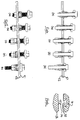
Figs. 1 and 2 illustrate in elevation two variants of the fastener adapter of the invention, in combination with a machine screw and nut; -
Fig. 3 illustrates an exploded fastener adapter according to the invention in cross section, in combination with a machine screw and nut; -
Fig. 4 illustrates in axial section the steps of installation of the blind fastener of the invention; -
Fig. 5 corresponds toFig. 4 , and shows the fastener in full side elevation; -
Fig. 6 illustrates a suitable form locking arrangement between collar and ring; -
Fig. 7 illustrates an alternative embodiment having a load spreading washer; -
Fig. 8 shows the embodiment ofFig. 7 in axial section, and in the assembled condition; -
Fig. 9 is a further alternative having a fitting spring; -
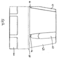
Figs. 10 to 12 show alternative gripping teeth for segments of the segmented ring; -
Fig. 13 illustrates in elevation an elastomeric fitting ring of the tapered collar; -
Fig. 14 shows a perspective view of a plurality of fastener adapters having differing shouldered washer configurations; -
Fig. 15 shows a cross-sectional view of the fastener adapters offigure 14 ; -
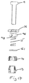
Fig. 16 shows a exploded side view of a fastener adapter according to an embodiment of the present invention and a machine screw, and -
Fig. 17 shows a cross-sectional view of the fastener adapter and machine screw offigure 16 . - With reference to
Figs. 1 to 3 , a fastener comprises a conventional hexagonalheaded machine screw 11 having acorresponding hexagon nut 12 of the same size. Between the head of the machine screw and the nut the components of an adapter comprise in series, atapered collar 13, a segmentedring 14, acoil compression spring 15 and ashouldered washer 16. The adapter renders the standard screw and nut suitable for blind (one-sided) installation, and may be filled to the machine screw and nut in either orientation, as illustrated inFigs. 1 and 2 , with the proviso that in use the fastener enters a corresponding hole collar first. - The
collar 13 comprises aplain diameter portion 21 for contact with the adjacent hexagon and a tapered portion 22 having three equi-spaced protrudingrails 23. Each rail has an enlarged head 24 (Fig. 6 ) of constant section. Therails 23 extend in the direction of the axis of the fastener, and the bore 25 of the collar allows free movement along the threads of the fastener. - The ring comprises three identical and equi-
spaced segments 31 each having an undercut recess 32 (Fig. 6 ) for sliding engagement with the respective enlarged head 24. The internal surfaces of thesegments 31 are arcuate and conical in form, so as to match the conical form of thecollar 13. The proximal side of the segments is shouldered so that inuse ring 14 fits closely in the distal side of a hole for which the fastener is intended. - The
spring 15 is a light wire coil compression spring, which in use biases the segments of thering 14 towards the collar 13 (downwardly as viewed inFig. 3 ). - The
shouldered washer 16 has asmaller diameter 41 adapted for close fitting engagement in the proximal side of a hole for which the fastener is intended. Theinternal diameter 42 is also relieved to accommodate the proximal end of thespring 15, and is of sufficient depth to accept the spring without coil binding. In other words the spring can be fully compressed and housed within thewasher 16, for reasons which will become apparent. - In order to convert a standard fastener to blind use, the components of the assembly are assembled in the manner indicated in
Fig. 1 or Fig. 2 - thecoil spring 15 lightly biases thering 14 and collar 13 into engagement, and thering 14 tends to adopt a position at the base of the taper of thecollar 13, as illustrated inFigs. 1 and 2 . In this condition, the outside diameter of the ring is greater than theplain portion 21 of the collar. - With reference to
Figs. 4 and 5 , the blind fastener assembly is offered up to a hole, collar first. In the illustrated case a through hole of twoplates collar 13 pass freely through the hole, but thering 14 does not (Fig. 4a ). Further light insertion pressure causes thespring 15 to collapse (Fig. 4b ) as the collar and ring separate thesegments 31 move radially inwardly in consequence of the form-locking profile ofFig. 6 . - The taper is arranged so that the segments are drawn sufficiently inwardly to eventually pass through the hole (
Fig. 4c ) under pressure from thespring 15, whereupon the collar and ring become more closely engaged again, which in turn guides the segments to a radially outer condition in which the shouldered portion of the ring engages in the distal side of the hole (Fig. 4d ). - The proximal side hexagon may now be turned to tighten the fastener by hand, a slight proximal pull being sufficient to ensure frictional drag on the distal side hexagon. The drag force may be enhanced by suitable raised formations of the areas in contact, or alternatively the collar may be arranged to lightly grip the adjacent hexagon.
- Final tightening is by spanner or torque wrench, the spring being fully housed within the shouldered washer so as not to impede engagement of the
ring 14 anddistal side plate 52. - The hexagons are selected so as to pass through the hole, though it will be understood that this is not a functional requirement for the distal side hexagon. Furthermore hexagon heads are not essential to the invention, and could be replaced by equivalent means such as screwdriver slots, or cap heads incorporating a recessed fastener drive form. Use of the blind fastener according to this invention is intuitive, and accordingly incorrect installation is unlikely.
- In the illustrated embodiment, the fastener is used to clamp two plates together. However the invention is also suitable for forming a load bearing attachment in any planar surface of which access to the distal side is restricted. A particular use of the invention is providing fixings to hollow sections.
-
Fig. 7 shows a variation of the embodiment ofFigs. 1 to 6 , in which thewasher 61 is provided on the proximal side of thering 14, and against which thelight spring 15 acts. Thewasher 61 is selected to be of smaller diameter than the hole for which the fastener is intended, and is preferably a close fit for reasons which will become apparent. Thewasher 61 may include a circular recess (not shown) on the proximal side to better locate the spring so as to avoid contact with the screw threads. - The
washer 61 ensures synchronised movement of the segments and, as illustrated inFig. 8 , provides additional support against lateral shearing and bearing forces which tend to tip the fastener in the hole, and are illustrated byarrows 62. The thickness of theadditional washer 61 is in practice selected to suit the thickness of the hole for which the fastener is intended, taking into account an allowance for the spigot diameter of the standard shoulderedwasher 16 and thecollar 14.Fig. 8 clearly shows how thelight spring 15 is housed in a recess of thewasher 16 when the components are in the assembled condition. -
Figs. 7 and 8 also illustrate that it is possible to combine thenut 12 andcollar 13 into a single component comprising a threadedcone 63.External flats 64 or like features may be provided on the cone blank to facilitate holding during thread tapping. -
Fig. 9 illustrates a further modification whereby an additionalcoil compression spring 65 is provided external to thelight spring 15, and oppositely wound to avoid coil binding. - During assembly, the
additional spring 65 bears on the proximal side of the material in which the hole is formed to ensure sufficient anti-rotational friction force between the distal side and the segmentedring 14. This feature may avoid the need to give a slight outward pull on the fastener during initial fastening, and can be useful where access is restricted. Theadditional spring 65 may be used in conjunction with thewasher 61, or not, but is in any event provided with a corresponding recess in the shoulderedwasher 16 to obviate coil binding where the fastener is fully tightened. - A somewhat schematic representation of a preferred segment 71 is illustrated in
Fig. 10 and comprises aplain diameter portion 72, a taperedportion 73 and adovetail recess 74 which corresponds to a suitable form of thecollar 13. Grippingteeth 75 of suitable form are provided at theshoulders 76 so as to engage the distal side of the hole in use, and contribute to anti-rotation during initial assembly. - The gripping
teeth 75 may extend radially to a partial extent (Fig. 10 ), radially to a full extent (Fig. 11 ), axially to a partial or full extent (Fig. 12 ), or in both radial and axial directions as required by the circumstances of the installation. - A further enhancement is illustrated in
Fig. 13 , in which a composite collar andnut 63 has three equi-spacedmale dovetail projections 67 at the base of which are respective groove 66. Retained by the grooves is a soft elastomeric ring 68, for example a synthetic rubber O-ring. The axial position of the grooves and the diameter of the O-ring is selected so that in the uninstalled condition, the distal side of the segmentedring 14 is prevented from bottoming on the collar, so that the outside diameter of the segmented ring is just less than the diameter of the hole. In this condition, the fastener will pass freely through to the blind side. - However, upon tightening, the ring 68 collapses or is displaced to permit the segments to come into functional engagement with the collar, either directly or through compression of the ring, and thus cause the radial movement necessary for engagement of the segmented
ring 14 with the distal side of the hole. The ring 68 is essentially a single use fitting component intended to provide smooth passage of the fastener to the distal side of the hole. - It will be understood that the fitting ring 68 may also be used with a separate nut, the location feature of the ring being provided on the collar.
- It will further be appreciated that the shouldered
washer 16 may have different configurations depending upon the application of the blind fastener.Figures 14 and15 illustrate a plurality of different possible shouldered washer configurations. The examples shown are not intended to be limiting, but merely illustrate a selection of possible configurations. In the examples shown infigures 14 and15 thenut 12 of thescrew 11 is not shown - Examples A and B of
figures 14 and15 show a shoulderedwasher 16 having a configuration substantially has hereinbefore described. Thewasher 16 includes a reduceddiameter portion 41 adapted for close fitting to the sides of the hole through which fastener extends. - Example C shows a shouldered washer 16' having a
peripheral wall 78 which defines arecess 80. The hexagonal head of themachine screw 11 is received in the recess with sufficient clearance that an appropriately sized socket or box spanner can fit over the head. The height of thewall 78 is such thatuppermost edge 82 of the shouldered washer 16' extends above the head of themachine screw 11. - Example D shows a shouldered
washer 16" which is similar to that of example C. Thewasher 16" differs in that theperipheral wall 78 is tapered 84 such that thewasher 16" has a semi-domed appearance. - Example E shows a shouldered
washer 16"' which is adapted for use with a countersunkscrew 11. Thewasher 16"' is provided with a through aperture 86 having a tapered portion 88 which accommodates the corresponding taper of thescrew 11 such that theuppermost face 90 of thescrew 11 is aligned substantially at the same level as theuppermost edge 82 of the washer 16'". - Example F shows a further example of a shouldered
washer 16"" adapted for use with a countersunkscrew 11. In this example the shoulderedwasher 16"" is configured such that it is received in a countersunk hole 92, with the result that both thewasher 16"" and head of the countersunkscrew 11 are substantially flush with theupper plate 51. Thewasher 16"" is provided with tapered outer surface 94 which is dimensioned so as to be received within the countersunk hole 92. -
Figures 16 and17 show an alternative embodiment of a fastener adapter and machine screw in accordance with the present invention. Features common to the previously described embodiments are identified with like reference numerals. Thehexagon nut 12 is not shown. - The fastener adapter includes a
shear bush 96 which is positioned intermediate the shoulderedwasher 16 and thespring 15. Theshear bush 96 is substantially tubular and includes a throughbore 98. The throughbore 98 may be plain such that thebush 96 is a sliding fit over the thread of thescrew 11. Alternatively, the throughbore 98 may be provided with a thread such that thebush 96 may be threaded on to the thread of the screw. In use, thebush 96 is positioned in the hole extending through the twoplates plates bush 96 is dependent upon the thickness of theplates - Several modifications and alternatives have been described, and may be used independently or in combination to provide the required technical characteristics for a particular installation.
Claims (16)
- A blind fastener adapter for a conventional screw-threaded nut (12) and screw (11), the adapter comprising a collar (13) and a segmented ring (14) over the collar (13), the ring (14) and collar (13) having a tapered interface wherein relative axial movement results in a change of diameter of said ring (14), said adapter further including a spring (15) adapted to bias said collar (13) and ring (14) into mutual engagement, said collar (13) and ring (14) including means to prevent substantial relative angular movement thereof, said collar (13) being adapted for engagement by a blind side head of said screw (11) in use, and said ring (14) being adapted for blind side engagement of the perimeter of a hole, characterised in that the spring (15) is a coil compression spring that axially biases said collar (13) and ring (14) into mutual engagement in use.
- A blind fastener adapter as claimed in claim 1 wherein the blind side head is a nut (12) or the head of a male fastener, such as a machine screw or bolt (11).
- A blind fastener adapter for a conventional screw-threaded screw (11), the adapter comprising a collar (13) and a segmented ring (14) over the collar (13), the ring (14) and collar (13) having a tapered interface wherein relative axial movement results in a change of diameter of said ring (14), said adapter further including a spring (15) adapted to bias said collar (13) and ring (14) into mutual engagement, said collar (13) and ring (14) including means to prevent substantial relative angular movement thereof, said collar (13) being threaded for engagement by a blind side thread of said screw (11) in use, and said ring (14) being adapted for blind side engagement of the perimeter of a hole, characterised in that the spring (15) is a coil compression spring that axially biases said collar (13) and ring (14) into mutual engagement in use.
- A blind fastener adapter as claimed in any preceding claims wherein the screw (11) is a threaded stud, or the shank of a male fastener.
- A blind fastener adapter as claimed in any preceding claim wherein the ring (14) and collar (13) are fixed against relative rotation by dogs.
- A blind fastener adapter as claimed in claim 5 wherein the dogs comprise protrusions of one of the ring (14) and collar (13), and mating recesses of the other of the ring (14) and collar (13).
- A blind fastener adapter as claimed in claim 6 wherein protruding rails (23) of the collar (13) extend in the direction of the axis of rotation thereof, and engage in close fitting grooves of the ring (14).
- A blind fastener adapter as claimed in any of claims 5 to 7 wherein the ring (14) has three segments (31), each segment (31) being restrained by a suitable dog.
- A blind fastener adapter as claimed in claim 8 wherein each segment (31) is retained against radial separation by the collar (13).
- A blind fastener adapter as claimed in claim 9 wherein each segment (31) is retained against radial separation by an enlarged head (24) of a rail (23) engageable in an undercut groove (32).
- A blind fastener adapter as claimed in claim 1 or claim 2 wherein the spring (15) bears directly on said ring (14) in use, and is sized to fit closely around said screw.
- A blind fastener adapter as claimed in any of claims 1 to 10 and further including a collared washer (16) at the proximal side of said coil spring (15).
- A blind fastener adapter as claimed in claim 12 wherein a reduced diameter (41) of said washer (16) is sized to engage closely within the hole for which the fastener is intended to fit, and the washer (16) has an internal recess of sufficient depth to accept said spring (15) when compressed.
- A blind fastener adapter as claimed in claim 3 and further including a tubular bush (96) positioned between the collared washer (16) and the proximal side of said coil spring.
- A blind fastener adapter as claimed in any preceding claim wherein the ring (14) has a reduced diameter portion at the proximal side so as to present a shoulder, the reduced diameter portion also being sized for close fitting engagement in the hole for which the fastener is intended, and the shoulder bearing on the perimeter of the distal side of the hole in use.
- A blind fastener adapter as claimed in claim 3 wherein a further washer (61) is provided proximally of the segmented ring (14) so as to distribute spring loads applied thereto.
Priority Applications (1)
| Application Number | Priority Date | Filing Date | Title |
|---|---|---|---|
| EP11194566.3A EP2607719B1 (en) | 2011-12-20 | 2011-12-20 | Blind fastener |
Applications Claiming Priority (1)
| Application Number | Priority Date | Filing Date | Title |
|---|---|---|---|
| EP11194566.3A EP2607719B1 (en) | 2011-12-20 | 2011-12-20 | Blind fastener |
Publications (2)
| Publication Number | Publication Date |
|---|---|
| EP2607719A1 EP2607719A1 (en) | 2013-06-26 |
| EP2607719B1 true EP2607719B1 (en) | 2016-08-03 |
Family
ID=45406470
Family Applications (1)
| Application Number | Title | Priority Date | Filing Date |
|---|---|---|---|
| EP11194566.3A Active EP2607719B1 (en) | 2011-12-20 | 2011-12-20 | Blind fastener |
Country Status (1)
| Country | Link |
|---|---|
| EP (1) | EP2607719B1 (en) |
Families Citing this family (1)
| Publication number | Priority date | Publication date | Assignee | Title |
|---|---|---|---|---|
| CN114810771B (en) * | 2022-05-26 | 2024-06-18 | 贵州航太精密制造有限公司 | Self-rebound non-falling screw and use method thereof |
Citations (1)
| Publication number | Priority date | Publication date | Assignee | Title |
|---|---|---|---|---|
| EP0175273A1 (en) * | 1984-09-17 | 1986-03-26 | Paolo Giovanni Morassutti | Anchor plug of the expanding type |
Family Cites Families (3)
| Publication number | Priority date | Publication date | Assignee | Title |
|---|---|---|---|---|
| US20040208722A1 (en) * | 2003-04-17 | 2004-10-21 | Pop-In Pop-Out, Inc. | Fastener adapted for use with a structural member |
| DE102005026942A1 (en) * | 2005-06-06 | 2006-12-07 | Christian Linde | Anchor bolt for attaching parts e.g. in automotive engineering, has anchor arms pulled together by elastic retaining rings that are stuck together for clamping block to carry back anchor block in its outlet positions |
| GB2477361B (en) * | 2010-05-04 | 2014-04-09 | Cedric Terence Cooke | Radially expandable assembly and use thereof |
-
2011
- 2011-12-20 EP EP11194566.3A patent/EP2607719B1/en active Active
Patent Citations (1)
| Publication number | Priority date | Publication date | Assignee | Title |
|---|---|---|---|---|
| EP0175273A1 (en) * | 1984-09-17 | 1986-03-26 | Paolo Giovanni Morassutti | Anchor plug of the expanding type |
Also Published As
| Publication number | Publication date |
|---|---|
| EP2607719A1 (en) | 2013-06-26 |
Similar Documents
| Publication | Publication Date | Title |
|---|---|---|
| US9145908B2 (en) | Blind fastener | |
| US12297854B2 (en) | Shear bolt with safety feature | |
| CA2868329C (en) | Blind fastener | |
| CN204591923U (en) | Quick-acting fastening | |
| US11208808B2 (en) | Barrier cable coupler | |
| US20070258786A1 (en) | Rivet-like fastener with floating nut | |
| GB2376053A (en) | Blind rivet nut | |
| US7004702B2 (en) | System for connecting elements | |
| WO2015118702A1 (en) | Bolt provided with locking function | |
| US20110182689A1 (en) | Blind Fastener System | |
| JP5413995B2 (en) | bolt | |
| US20210033139A1 (en) | Wire thread insert | |
| US20080193249A1 (en) | Laminated nut with tension indicator | |
| EP2607719A1 (en) | Blind fastener | |
| GB2481206A (en) | Blind fastener adapter | |
| AU2013207546B2 (en) | Blind fastener | |
| US4812097A (en) | Spring action fastener | |
| US6537004B2 (en) | Blind fastener and drive nut assembly | |
| US9180564B2 (en) | Device for securing a cap screw to an element that is to be attached to another element | |
| CA2002847A1 (en) | Panel anchor | |
| CA2194164A1 (en) | Self-locking threaded connecting device | |
| EP0741250A1 (en) | Fasteners | |
| US11680598B2 (en) | Fixing device | |
| WO2005124164A1 (en) | A fixing | |
| CN113366228A (en) | Fastener device for producing a threaded connection |
Legal Events
| Date | Code | Title | Description |
|---|---|---|---|
| AK | Designated contracting states |
Kind code of ref document: A1 Designated state(s): AL AT BE BG CH CY CZ DE DK EE ES FI FR GB GR HR HU IE IS IT LI LT LU LV MC MK MT NL NO PL PT RO RS SE SI SK SM TR |
|
| AX | Request for extension of the european patent |
Extension state: BA ME |
|
| PUAI | Public reference made under article 153(3) epc to a published international application that has entered the european phase |
Free format text: ORIGINAL CODE: 0009012 |
|
| 17P | Request for examination filed |
Effective date: 20131211 |
|
| RBV | Designated contracting states (corrected) |
Designated state(s): AL AT BE BG CH CY CZ DE DK EE ES FI FR GB GR HR HU IE IS IT LI LT LU LV MC MK MT NL NO PL PT RO RS SE SI SK SM TR |
|
| RIC1 | Information provided on ipc code assigned before grant |
Ipc: F16B 5/02 20060101AFI20140701BHEP |
|
| 17Q | First examination report despatched |
Effective date: 20141110 |
|
| GRAP | Despatch of communication of intention to grant a patent |
Free format text: ORIGINAL CODE: EPIDOSNIGR1 |
|
| INTG | Intention to grant announced |
Effective date: 20160308 |
|
| GRAS | Grant fee paid |
Free format text: ORIGINAL CODE: EPIDOSNIGR3 |
|
| GRAA | (expected) grant |
Free format text: ORIGINAL CODE: 0009210 |
|
| AK | Designated contracting states |
Kind code of ref document: B1 Designated state(s): AL AT BE BG CH CY CZ DE DK EE ES FI FR GB GR HR HU IE IS IT LI LT LU LV MC MK MT NL NO PL PT RO RS SE SI SK SM TR |
|
| REG | Reference to a national code |
Ref country code: GB Ref legal event code: FG4D |
|
| REG | Reference to a national code |
Ref country code: CH Ref legal event code: EP Ref country code: AT Ref legal event code: REF Ref document number: 817533 Country of ref document: AT Kind code of ref document: T Effective date: 20160815 |
|
| REG | Reference to a national code |
Ref country code: IE Ref legal event code: FG4D |
|
| REG | Reference to a national code |
Ref country code: DE Ref legal event code: R096 Ref document number: 602011028756 Country of ref document: DE |
|
| REG | Reference to a national code |
Ref country code: NL Ref legal event code: MP Effective date: 20160803 |
|
| REG | Reference to a national code |
Ref country code: LT Ref legal event code: MG4D |
|
| REG | Reference to a national code |
Ref country code: FR Ref legal event code: PLFP Year of fee payment: 6 |
|
| REG | Reference to a national code |
Ref country code: AT Ref legal event code: MK05 Ref document number: 817533 Country of ref document: AT Kind code of ref document: T Effective date: 20160803 |
|
| PG25 | Lapsed in a contracting state [announced via postgrant information from national office to epo] |
Ref country code: NL Free format text: LAPSE BECAUSE OF FAILURE TO SUBMIT A TRANSLATION OF THE DESCRIPTION OR TO PAY THE FEE WITHIN THE PRESCRIBED TIME-LIMIT Effective date: 20160803 Ref country code: IS Free format text: LAPSE BECAUSE OF FAILURE TO SUBMIT A TRANSLATION OF THE DESCRIPTION OR TO PAY THE FEE WITHIN THE PRESCRIBED TIME-LIMIT Effective date: 20161203 Ref country code: IT Free format text: LAPSE BECAUSE OF FAILURE TO SUBMIT A TRANSLATION OF THE DESCRIPTION OR TO PAY THE FEE WITHIN THE PRESCRIBED TIME-LIMIT Effective date: 20160803 Ref country code: RS Free format text: LAPSE BECAUSE OF FAILURE TO SUBMIT A TRANSLATION OF THE DESCRIPTION OR TO PAY THE FEE WITHIN THE PRESCRIBED TIME-LIMIT Effective date: 20160803 Ref country code: FI Free format text: LAPSE BECAUSE OF FAILURE TO SUBMIT A TRANSLATION OF THE DESCRIPTION OR TO PAY THE FEE WITHIN THE PRESCRIBED TIME-LIMIT Effective date: 20160803 Ref country code: LT Free format text: LAPSE BECAUSE OF FAILURE TO SUBMIT A TRANSLATION OF THE DESCRIPTION OR TO PAY THE FEE WITHIN THE PRESCRIBED TIME-LIMIT Effective date: 20160803 Ref country code: HR Free format text: LAPSE BECAUSE OF FAILURE TO SUBMIT A TRANSLATION OF THE DESCRIPTION OR TO PAY THE FEE WITHIN THE PRESCRIBED TIME-LIMIT Effective date: 20160803 Ref country code: NO Free format text: LAPSE BECAUSE OF FAILURE TO SUBMIT A TRANSLATION OF THE DESCRIPTION OR TO PAY THE FEE WITHIN THE PRESCRIBED TIME-LIMIT Effective date: 20161103 |
|
| PG25 | Lapsed in a contracting state [announced via postgrant information from national office to epo] |
Ref country code: PL Free format text: LAPSE BECAUSE OF FAILURE TO SUBMIT A TRANSLATION OF THE DESCRIPTION OR TO PAY THE FEE WITHIN THE PRESCRIBED TIME-LIMIT Effective date: 20160803 Ref country code: SE Free format text: LAPSE BECAUSE OF FAILURE TO SUBMIT A TRANSLATION OF THE DESCRIPTION OR TO PAY THE FEE WITHIN THE PRESCRIBED TIME-LIMIT Effective date: 20160803 Ref country code: GR Free format text: LAPSE BECAUSE OF FAILURE TO SUBMIT A TRANSLATION OF THE DESCRIPTION OR TO PAY THE FEE WITHIN THE PRESCRIBED TIME-LIMIT Effective date: 20161104 Ref country code: PT Free format text: LAPSE BECAUSE OF FAILURE TO SUBMIT A TRANSLATION OF THE DESCRIPTION OR TO PAY THE FEE WITHIN THE PRESCRIBED TIME-LIMIT Effective date: 20161205 Ref country code: AT Free format text: LAPSE BECAUSE OF FAILURE TO SUBMIT A TRANSLATION OF THE DESCRIPTION OR TO PAY THE FEE WITHIN THE PRESCRIBED TIME-LIMIT Effective date: 20160803 Ref country code: ES Free format text: LAPSE BECAUSE OF FAILURE TO SUBMIT A TRANSLATION OF THE DESCRIPTION OR TO PAY THE FEE WITHIN THE PRESCRIBED TIME-LIMIT Effective date: 20160803 Ref country code: LV Free format text: LAPSE BECAUSE OF FAILURE TO SUBMIT A TRANSLATION OF THE DESCRIPTION OR TO PAY THE FEE WITHIN THE PRESCRIBED TIME-LIMIT Effective date: 20160803 |
|
| PG25 | Lapsed in a contracting state [announced via postgrant information from national office to epo] |
Ref country code: EE Free format text: LAPSE BECAUSE OF FAILURE TO SUBMIT A TRANSLATION OF THE DESCRIPTION OR TO PAY THE FEE WITHIN THE PRESCRIBED TIME-LIMIT Effective date: 20160803 Ref country code: RO Free format text: LAPSE BECAUSE OF FAILURE TO SUBMIT A TRANSLATION OF THE DESCRIPTION OR TO PAY THE FEE WITHIN THE PRESCRIBED TIME-LIMIT Effective date: 20160803 |
|
| REG | Reference to a national code |
Ref country code: DE Ref legal event code: R097 Ref document number: 602011028756 Country of ref document: DE |
|
| PG25 | Lapsed in a contracting state [announced via postgrant information from national office to epo] |
Ref country code: BE Free format text: LAPSE BECAUSE OF FAILURE TO SUBMIT A TRANSLATION OF THE DESCRIPTION OR TO PAY THE FEE WITHIN THE PRESCRIBED TIME-LIMIT Effective date: 20160803 Ref country code: BG Free format text: LAPSE BECAUSE OF FAILURE TO SUBMIT A TRANSLATION OF THE DESCRIPTION OR TO PAY THE FEE WITHIN THE PRESCRIBED TIME-LIMIT Effective date: 20161103 Ref country code: CZ Free format text: LAPSE BECAUSE OF FAILURE TO SUBMIT A TRANSLATION OF THE DESCRIPTION OR TO PAY THE FEE WITHIN THE PRESCRIBED TIME-LIMIT Effective date: 20160803 Ref country code: DK Free format text: LAPSE BECAUSE OF FAILURE TO SUBMIT A TRANSLATION OF THE DESCRIPTION OR TO PAY THE FEE WITHIN THE PRESCRIBED TIME-LIMIT Effective date: 20160803 Ref country code: SK Free format text: LAPSE BECAUSE OF FAILURE TO SUBMIT A TRANSLATION OF THE DESCRIPTION OR TO PAY THE FEE WITHIN THE PRESCRIBED TIME-LIMIT Effective date: 20160803 Ref country code: SM Free format text: LAPSE BECAUSE OF FAILURE TO SUBMIT A TRANSLATION OF THE DESCRIPTION OR TO PAY THE FEE WITHIN THE PRESCRIBED TIME-LIMIT Effective date: 20160803 |
|
| PLBE | No opposition filed within time limit |
Free format text: ORIGINAL CODE: 0009261 |
|
| STAA | Information on the status of an ep patent application or granted ep patent |
Free format text: STATUS: NO OPPOSITION FILED WITHIN TIME LIMIT |
|
| 26N | No opposition filed |
Effective date: 20170504 |
|
| REG | Reference to a national code |
Ref country code: CH Ref legal event code: PL |
|
| PG25 | Lapsed in a contracting state [announced via postgrant information from national office to epo] |
Ref country code: SI Free format text: LAPSE BECAUSE OF FAILURE TO SUBMIT A TRANSLATION OF THE DESCRIPTION OR TO PAY THE FEE WITHIN THE PRESCRIBED TIME-LIMIT Effective date: 20160803 |
|
| PG25 | Lapsed in a contracting state [announced via postgrant information from national office to epo] |
Ref country code: MC Free format text: LAPSE BECAUSE OF FAILURE TO SUBMIT A TRANSLATION OF THE DESCRIPTION OR TO PAY THE FEE WITHIN THE PRESCRIBED TIME-LIMIT Effective date: 20160803 |
|
| PG25 | Lapsed in a contracting state [announced via postgrant information from national office to epo] |
Ref country code: LI Free format text: LAPSE BECAUSE OF NON-PAYMENT OF DUE FEES Effective date: 20161231 Ref country code: CH Free format text: LAPSE BECAUSE OF NON-PAYMENT OF DUE FEES Effective date: 20161231 Ref country code: LU Free format text: LAPSE BECAUSE OF NON-PAYMENT OF DUE FEES Effective date: 20161220 |
|
| REG | Reference to a national code |
Ref country code: FR Ref legal event code: PLFP Year of fee payment: 7 |
|
| PG25 | Lapsed in a contracting state [announced via postgrant information from national office to epo] |
Ref country code: HU Free format text: LAPSE BECAUSE OF FAILURE TO SUBMIT A TRANSLATION OF THE DESCRIPTION OR TO PAY THE FEE WITHIN THE PRESCRIBED TIME-LIMIT; INVALID AB INITIO Effective date: 20111220 Ref country code: CY Free format text: LAPSE BECAUSE OF FAILURE TO SUBMIT A TRANSLATION OF THE DESCRIPTION OR TO PAY THE FEE WITHIN THE PRESCRIBED TIME-LIMIT Effective date: 20160803 |
|
| PG25 | Lapsed in a contracting state [announced via postgrant information from national office to epo] |
Ref country code: TR Free format text: LAPSE BECAUSE OF FAILURE TO SUBMIT A TRANSLATION OF THE DESCRIPTION OR TO PAY THE FEE WITHIN THE PRESCRIBED TIME-LIMIT Effective date: 20160803 Ref country code: MK Free format text: LAPSE BECAUSE OF FAILURE TO SUBMIT A TRANSLATION OF THE DESCRIPTION OR TO PAY THE FEE WITHIN THE PRESCRIBED TIME-LIMIT Effective date: 20160803 |
|
| PG25 | Lapsed in a contracting state [announced via postgrant information from national office to epo] |
Ref country code: MT Free format text: LAPSE BECAUSE OF NON-PAYMENT OF DUE FEES Effective date: 20161220 |
|
| PG25 | Lapsed in a contracting state [announced via postgrant information from national office to epo] |
Ref country code: AL Free format text: LAPSE BECAUSE OF FAILURE TO SUBMIT A TRANSLATION OF THE DESCRIPTION OR TO PAY THE FEE WITHIN THE PRESCRIBED TIME-LIMIT Effective date: 20160803 |
|
| REG | Reference to a national code |
Ref country code: DE Ref legal event code: R082 Ref document number: 602011028756 Country of ref document: DE Representative=s name: 4IP GLEIMPETRI PATENT- UND RECHTSANWALTSPARTNE, DE |
|
| PGFP | Annual fee paid to national office [announced via postgrant information from national office to epo] |
Ref country code: GB Payment date: 20251216 Year of fee payment: 15 |
|
| PGFP | Annual fee paid to national office [announced via postgrant information from national office to epo] |
Ref country code: FR Payment date: 20251223 Year of fee payment: 15 |
|
| PGFP | Annual fee paid to national office [announced via postgrant information from national office to epo] |
Ref country code: IE Payment date: 20251219 Year of fee payment: 15 |
|
| PGFP | Annual fee paid to national office [announced via postgrant information from national office to epo] |
Ref country code: DE Payment date: 20251230 Year of fee payment: 15 |