EP2607661A2 - Electrical Connectors - Google Patents
Electrical Connectors Download PDFInfo
- Publication number
- EP2607661A2 EP2607661A2 EP12197395.2A EP12197395A EP2607661A2 EP 2607661 A2 EP2607661 A2 EP 2607661A2 EP 12197395 A EP12197395 A EP 12197395A EP 2607661 A2 EP2607661 A2 EP 2607661A2
- Authority
- EP
- European Patent Office
- Prior art keywords
- electrical
- raft
- unit
- connector
- gas turbine
- Prior art date
- Legal status (The legal status is an assumption and is not a legal conclusion. Google has not performed a legal analysis and makes no representation as to the accuracy of the status listed.)
- Granted
Links
- 239000004020 conductor Substances 0.000 claims abstract description 73
- 239000000463 material Substances 0.000 claims abstract description 57
- 238000009434 installation Methods 0.000 claims description 24
- 238000000034 method Methods 0.000 claims description 17
- 239000007789 gas Substances 0.000 description 95
- 239000012530 fluid Substances 0.000 description 38
- 230000000712 assembly Effects 0.000 description 12
- 238000000429 assembly Methods 0.000 description 12
- 229920005989 resin Polymers 0.000 description 11
- 239000011347 resin Substances 0.000 description 11
- 239000002131 composite material Substances 0.000 description 9
- 239000000758 substrate Substances 0.000 description 9
- 238000012423 maintenance Methods 0.000 description 8
- 238000012546 transfer Methods 0.000 description 8
- 230000008901 benefit Effects 0.000 description 7
- 238000010276 construction Methods 0.000 description 7
- 239000000835 fiber Substances 0.000 description 6
- 239000000446 fuel Substances 0.000 description 6
- 238000012545 processing Methods 0.000 description 5
- RYGMFSIKBFXOCR-UHFFFAOYSA-N Copper Chemical compound [Cu] RYGMFSIKBFXOCR-UHFFFAOYSA-N 0.000 description 4
- 229910000881 Cu alloy Inorganic materials 0.000 description 4
- 238000009954 braiding Methods 0.000 description 4
- 150000001875 compounds Chemical class 0.000 description 4
- 239000010949 copper Substances 0.000 description 4
- 229910052802 copper Inorganic materials 0.000 description 4
- 238000002955 isolation Methods 0.000 description 4
- 239000007788 liquid Substances 0.000 description 4
- 230000007935 neutral effect Effects 0.000 description 4
- 230000008439 repair process Effects 0.000 description 4
- 238000002485 combustion reaction Methods 0.000 description 3
- 238000004891 communication Methods 0.000 description 3
- 238000004519 manufacturing process Methods 0.000 description 3
- 238000012544 monitoring process Methods 0.000 description 3
- 230000008569 process Effects 0.000 description 3
- 230000001141 propulsive effect Effects 0.000 description 3
- XQUPVDVFXZDTLT-UHFFFAOYSA-N 1-[4-[[4-(2,5-dioxopyrrol-1-yl)phenyl]methyl]phenyl]pyrrole-2,5-dione Chemical compound O=C1C=CC(=O)N1C(C=C1)=CC=C1CC1=CC=C(N2C(C=CC2=O)=O)C=C1 XQUPVDVFXZDTLT-UHFFFAOYSA-N 0.000 description 2
- 239000004696 Poly ether ether ketone Substances 0.000 description 2
- 239000004952 Polyamide Substances 0.000 description 2
- 229920003235 aromatic polyamide Polymers 0.000 description 2
- 230000005540 biological transmission Effects 0.000 description 2
- 238000001816 cooling Methods 0.000 description 2
- 210000003205 muscle Anatomy 0.000 description 2
- 239000003921 oil Substances 0.000 description 2
- 230000002093 peripheral effect Effects 0.000 description 2
- 229920003192 poly(bis maleimide) Polymers 0.000 description 2
- 229920002647 polyamide Polymers 0.000 description 2
- 229920006260 polyaryletherketone Polymers 0.000 description 2
- 229920002530 polyetherether ketone Polymers 0.000 description 2
- 229920001343 polytetrafluoroethylene Polymers 0.000 description 2
- 230000001681 protective effect Effects 0.000 description 2
- 238000007789 sealing Methods 0.000 description 2
- 230000008054 signal transmission Effects 0.000 description 2
- 238000012360 testing method Methods 0.000 description 2
- XLYOFNOQVPJJNP-UHFFFAOYSA-N water Substances O XLYOFNOQVPJJNP-UHFFFAOYSA-N 0.000 description 2
- OKTJSMMVPCPJKN-UHFFFAOYSA-N Carbon Chemical compound [C] OKTJSMMVPCPJKN-UHFFFAOYSA-N 0.000 description 1
- 239000004593 Epoxy Substances 0.000 description 1
- 239000004677 Nylon Substances 0.000 description 1
- 230000009471 action Effects 0.000 description 1
- 239000004411 aluminium Substances 0.000 description 1
- XAGFODPZIPBFFR-UHFFFAOYSA-N aluminium Chemical compound [Al] XAGFODPZIPBFFR-UHFFFAOYSA-N 0.000 description 1
- 229910052782 aluminium Inorganic materials 0.000 description 1
- 229910052799 carbon Inorganic materials 0.000 description 1
- 230000015556 catabolic process Effects 0.000 description 1
- 230000008859 change Effects 0.000 description 1
- 230000000295 complement effect Effects 0.000 description 1
- 230000006835 compression Effects 0.000 description 1
- 238000007906 compression Methods 0.000 description 1
- 239000000112 cooling gas Substances 0.000 description 1
- 230000003247 decreasing effect Effects 0.000 description 1
- 238000006731 degradation reaction Methods 0.000 description 1
- 238000013461 design Methods 0.000 description 1
- 238000001514 detection method Methods 0.000 description 1
- 230000005611 electricity Effects 0.000 description 1
- 239000011521 glass Substances 0.000 description 1
- 239000003365 glass fiber Substances 0.000 description 1
- 230000036541 health Effects 0.000 description 1
- 238000010438 heat treatment Methods 0.000 description 1
- 239000000314 lubricant Substances 0.000 description 1
- 238000003754 machining Methods 0.000 description 1
- 239000011159 matrix material Substances 0.000 description 1
- 238000005259 measurement Methods 0.000 description 1
- 239000000203 mixture Substances 0.000 description 1
- 229920001778 nylon Polymers 0.000 description 1
- 239000004814 polyurethane Substances 0.000 description 1
- 229920002635 polyurethane Polymers 0.000 description 1
- 239000000523 sample Substances 0.000 description 1
Images


Classifications
-
- H—ELECTRICITY
- H05—ELECTRIC TECHNIQUES NOT OTHERWISE PROVIDED FOR
- H05B—ELECTRIC HEATING; ELECTRIC LIGHT SOURCES NOT OTHERWISE PROVIDED FOR; CIRCUIT ARRANGEMENTS FOR ELECTRIC LIGHT SOURCES, IN GENERAL
- H05B3/00—Ohmic-resistance heating
- H05B3/20—Heating elements having extended surface area substantially in a two-dimensional plane, e.g. plate-heater
- H05B3/22—Heating elements having extended surface area substantially in a two-dimensional plane, e.g. plate-heater non-flexible
- H05B3/28—Heating elements having extended surface area substantially in a two-dimensional plane, e.g. plate-heater non-flexible heating conductor embedded in insulating material
-
- B—PERFORMING OPERATIONS; TRANSPORTING
- B23—MACHINE TOOLS; METAL-WORKING NOT OTHERWISE PROVIDED FOR
- B23P—METAL-WORKING NOT OTHERWISE PROVIDED FOR; COMBINED OPERATIONS; UNIVERSAL MACHINE TOOLS
- B23P6/00—Restoring or reconditioning objects
- B23P6/002—Repairing turbine components, e.g. moving or stationary blades, rotors
- B23P6/005—Repairing turbine components, e.g. moving or stationary blades, rotors using only replacement pieces of a particular form
-
- B—PERFORMING OPERATIONS; TRANSPORTING
- B60—VEHICLES IN GENERAL
- B60R—VEHICLES, VEHICLE FITTINGS, OR VEHICLE PARTS, NOT OTHERWISE PROVIDED FOR
- B60R16/00—Electric or fluid circuits specially adapted for vehicles and not otherwise provided for; Arrangement of elements of electric or fluid circuits specially adapted for vehicles and not otherwise provided for
- B60R16/02—Electric or fluid circuits specially adapted for vehicles and not otherwise provided for; Arrangement of elements of electric or fluid circuits specially adapted for vehicles and not otherwise provided for electric constitutive elements
- B60R16/0207—Wire harnesses
- B60R16/0215—Protecting, fastening and routing means therefor
-
- B—PERFORMING OPERATIONS; TRANSPORTING
- B60—VEHICLES IN GENERAL
- B60R—VEHICLES, VEHICLE FITTINGS, OR VEHICLE PARTS, NOT OTHERWISE PROVIDED FOR
- B60R16/00—Electric or fluid circuits specially adapted for vehicles and not otherwise provided for; Arrangement of elements of electric or fluid circuits specially adapted for vehicles and not otherwise provided for
- B60R16/08—Electric or fluid circuits specially adapted for vehicles and not otherwise provided for; Arrangement of elements of electric or fluid circuits specially adapted for vehicles and not otherwise provided for fluid
-
- B—PERFORMING OPERATIONS; TRANSPORTING
- B64—AIRCRAFT; AVIATION; COSMONAUTICS
- B64C—AEROPLANES; HELICOPTERS
- B64C3/00—Wings
- B64C3/34—Tanks constructed integrally with wings, e.g. for fuel or water
-
- B—PERFORMING OPERATIONS; TRANSPORTING
- B64—AIRCRAFT; AVIATION; COSMONAUTICS
- B64D—EQUIPMENT FOR FITTING IN OR TO AIRCRAFT; FLIGHT SUITS; PARACHUTES; ARRANGEMENTS OR MOUNTING OF POWER PLANTS OR PROPULSION TRANSMISSIONS IN AIRCRAFT
- B64D29/00—Power-plant nacelles, fairings, or cowlings
- B64D29/08—Inspection panels for power plants
-
- F—MECHANICAL ENGINEERING; LIGHTING; HEATING; WEAPONS; BLASTING
- F01—MACHINES OR ENGINES IN GENERAL; ENGINE PLANTS IN GENERAL; STEAM ENGINES
- F01D—NON-POSITIVE DISPLACEMENT MACHINES OR ENGINES, e.g. STEAM TURBINES
- F01D25/00—Component parts, details, or accessories, not provided for in, or of interest apart from, other groups
- F01D25/28—Supporting or mounting arrangements, e.g. for turbine casing
-
- F—MECHANICAL ENGINEERING; LIGHTING; HEATING; WEAPONS; BLASTING
- F02—COMBUSTION ENGINES; HOT-GAS OR COMBUSTION-PRODUCT ENGINE PLANTS
- F02C—GAS-TURBINE PLANTS; AIR INTAKES FOR JET-PROPULSION PLANTS; CONTROLLING FUEL SUPPLY IN AIR-BREATHING JET-PROPULSION PLANTS
- F02C7/00—Features, components parts, details or accessories, not provided for in, or of interest apart form groups F02C1/00 - F02C6/00; Air intakes for jet-propulsion plants
- F02C7/04—Air intakes for gas-turbine plants or jet-propulsion plants
- F02C7/047—Heating to prevent icing
-
- F—MECHANICAL ENGINEERING; LIGHTING; HEATING; WEAPONS; BLASTING
- F02—COMBUSTION ENGINES; HOT-GAS OR COMBUSTION-PRODUCT ENGINE PLANTS
- F02C—GAS-TURBINE PLANTS; AIR INTAKES FOR JET-PROPULSION PLANTS; CONTROLLING FUEL SUPPLY IN AIR-BREATHING JET-PROPULSION PLANTS
- F02C7/00—Features, components parts, details or accessories, not provided for in, or of interest apart form groups F02C1/00 - F02C6/00; Air intakes for jet-propulsion plants
- F02C7/12—Cooling of plants
- F02C7/14—Cooling of plants of fluids in the plant, e.g. lubricant or fuel
- F02C7/141—Cooling of plants of fluids in the plant, e.g. lubricant or fuel of working fluid
-
- F—MECHANICAL ENGINEERING; LIGHTING; HEATING; WEAPONS; BLASTING
- F02—COMBUSTION ENGINES; HOT-GAS OR COMBUSTION-PRODUCT ENGINE PLANTS
- F02C—GAS-TURBINE PLANTS; AIR INTAKES FOR JET-PROPULSION PLANTS; CONTROLLING FUEL SUPPLY IN AIR-BREATHING JET-PROPULSION PLANTS
- F02C7/00—Features, components parts, details or accessories, not provided for in, or of interest apart form groups F02C1/00 - F02C6/00; Air intakes for jet-propulsion plants
- F02C7/12—Cooling of plants
- F02C7/16—Cooling of plants characterised by cooling medium
-
- F—MECHANICAL ENGINEERING; LIGHTING; HEATING; WEAPONS; BLASTING
- F02—COMBUSTION ENGINES; HOT-GAS OR COMBUSTION-PRODUCT ENGINE PLANTS
- F02C—GAS-TURBINE PLANTS; AIR INTAKES FOR JET-PROPULSION PLANTS; CONTROLLING FUEL SUPPLY IN AIR-BREATHING JET-PROPULSION PLANTS
- F02C7/00—Features, components parts, details or accessories, not provided for in, or of interest apart form groups F02C1/00 - F02C6/00; Air intakes for jet-propulsion plants
- F02C7/20—Mounting or supporting of plant; Accommodating heat expansion or creep
-
- F—MECHANICAL ENGINEERING; LIGHTING; HEATING; WEAPONS; BLASTING
- F02—COMBUSTION ENGINES; HOT-GAS OR COMBUSTION-PRODUCT ENGINE PLANTS
- F02C—GAS-TURBINE PLANTS; AIR INTAKES FOR JET-PROPULSION PLANTS; CONTROLLING FUEL SUPPLY IN AIR-BREATHING JET-PROPULSION PLANTS
- F02C7/00—Features, components parts, details or accessories, not provided for in, or of interest apart form groups F02C1/00 - F02C6/00; Air intakes for jet-propulsion plants
- F02C7/22—Fuel supply systems
- F02C7/222—Fuel flow conduits, e.g. manifolds
-
- F—MECHANICAL ENGINEERING; LIGHTING; HEATING; WEAPONS; BLASTING
- F02—COMBUSTION ENGINES; HOT-GAS OR COMBUSTION-PRODUCT ENGINE PLANTS
- F02C—GAS-TURBINE PLANTS; AIR INTAKES FOR JET-PROPULSION PLANTS; CONTROLLING FUEL SUPPLY IN AIR-BREATHING JET-PROPULSION PLANTS
- F02C7/00—Features, components parts, details or accessories, not provided for in, or of interest apart form groups F02C1/00 - F02C6/00; Air intakes for jet-propulsion plants
- F02C7/22—Fuel supply systems
- F02C7/224—Heating fuel before feeding to the burner
-
- F—MECHANICAL ENGINEERING; LIGHTING; HEATING; WEAPONS; BLASTING
- F02—COMBUSTION ENGINES; HOT-GAS OR COMBUSTION-PRODUCT ENGINE PLANTS
- F02C—GAS-TURBINE PLANTS; AIR INTAKES FOR JET-PROPULSION PLANTS; CONTROLLING FUEL SUPPLY IN AIR-BREATHING JET-PROPULSION PLANTS
- F02C7/00—Features, components parts, details or accessories, not provided for in, or of interest apart form groups F02C1/00 - F02C6/00; Air intakes for jet-propulsion plants
- F02C7/32—Arrangement, mounting, or driving, of auxiliaries
-
- F—MECHANICAL ENGINEERING; LIGHTING; HEATING; WEAPONS; BLASTING
- F16—ENGINEERING ELEMENTS AND UNITS; GENERAL MEASURES FOR PRODUCING AND MAINTAINING EFFECTIVE FUNCTIONING OF MACHINES OR INSTALLATIONS; THERMAL INSULATION IN GENERAL
- F16M—FRAMES, CASINGS OR BEDS OF ENGINES, MACHINES OR APPARATUS, NOT SPECIFIC TO ENGINES, MACHINES OR APPARATUS PROVIDED FOR ELSEWHERE; STANDS; SUPPORTS
- F16M13/00—Other supports for positioning apparatus or articles; Means for steadying hand-held apparatus or articles
- F16M13/02—Other supports for positioning apparatus or articles; Means for steadying hand-held apparatus or articles for supporting on, or attaching to, an object, e.g. tree, gate, window-frame, cycle
-
- F—MECHANICAL ENGINEERING; LIGHTING; HEATING; WEAPONS; BLASTING
- F24—HEATING; RANGES; VENTILATING
- F24H—FLUID HEATERS, e.g. WATER OR AIR HEATERS, HAVING HEAT-GENERATING MEANS, e.g. HEAT PUMPS, IN GENERAL
- F24H1/00—Water heaters, e.g. boilers, continuous-flow heaters or water-storage heaters
- F24H1/10—Continuous-flow heaters, i.e. heaters in which heat is generated only while the water is flowing, e.g. with direct contact of the water with the heating medium
- F24H1/101—Continuous-flow heaters, i.e. heaters in which heat is generated only while the water is flowing, e.g. with direct contact of the water with the heating medium using electric energy supply
- F24H1/102—Continuous-flow heaters, i.e. heaters in which heat is generated only while the water is flowing, e.g. with direct contact of the water with the heating medium using electric energy supply with resistance
- F24H1/105—Continuous-flow heaters, i.e. heaters in which heat is generated only while the water is flowing, e.g. with direct contact of the water with the heating medium using electric energy supply with resistance formed by the tube through which the fluid flows
-
- H—ELECTRICITY
- H01—ELECTRIC ELEMENTS
- H01R—ELECTRICALLY-CONDUCTIVE CONNECTIONS; STRUCTURAL ASSOCIATIONS OF A PLURALITY OF MUTUALLY-INSULATED ELECTRICAL CONNECTING ELEMENTS; COUPLING DEVICES; CURRENT COLLECTORS
- H01R12/00—Structural associations of a plurality of mutually-insulated electrical connecting elements, specially adapted for printed circuits, e.g. printed circuit boards [PCB], flat or ribbon cables, or like generally planar structures, e.g. terminal strips, terminal blocks; Coupling devices specially adapted for printed circuits, flat or ribbon cables, or like generally planar structures; Terminals specially adapted for contact with, or insertion into, printed circuits, flat or ribbon cables, or like generally planar structures
- H01R12/50—Fixed connections
- H01R12/51—Fixed connections for rigid printed circuits or like structures
- H01R12/515—Terminal blocks providing connections to wires or cables
-
- H—ELECTRICITY
- H01—ELECTRIC ELEMENTS
- H01R—ELECTRICALLY-CONDUCTIVE CONNECTIONS; STRUCTURAL ASSOCIATIONS OF A PLURALITY OF MUTUALLY-INSULATED ELECTRICAL CONNECTING ELEMENTS; COUPLING DEVICES; CURRENT COLLECTORS
- H01R12/00—Structural associations of a plurality of mutually-insulated electrical connecting elements, specially adapted for printed circuits, e.g. printed circuit boards [PCB], flat or ribbon cables, or like generally planar structures, e.g. terminal strips, terminal blocks; Coupling devices specially adapted for printed circuits, flat or ribbon cables, or like generally planar structures; Terminals specially adapted for contact with, or insertion into, printed circuits, flat or ribbon cables, or like generally planar structures
- H01R12/50—Fixed connections
- H01R12/51—Fixed connections for rigid printed circuits or like structures
- H01R12/55—Fixed connections for rigid printed circuits or like structures characterised by the terminals
- H01R12/57—Fixed connections for rigid printed circuits or like structures characterised by the terminals surface mounting terminals
-
- H—ELECTRICITY
- H01—ELECTRIC ELEMENTS
- H01R—ELECTRICALLY-CONDUCTIVE CONNECTIONS; STRUCTURAL ASSOCIATIONS OF A PLURALITY OF MUTUALLY-INSULATED ELECTRICAL CONNECTING ELEMENTS; COUPLING DEVICES; CURRENT COLLECTORS
- H01R12/00—Structural associations of a plurality of mutually-insulated electrical connecting elements, specially adapted for printed circuits, e.g. printed circuit boards [PCB], flat or ribbon cables, or like generally planar structures, e.g. terminal strips, terminal blocks; Coupling devices specially adapted for printed circuits, flat or ribbon cables, or like generally planar structures; Terminals specially adapted for contact with, or insertion into, printed circuits, flat or ribbon cables, or like generally planar structures
- H01R12/50—Fixed connections
- H01R12/59—Fixed connections for flexible printed circuits, flat or ribbon cables or like structures
- H01R12/592—Fixed connections for flexible printed circuits, flat or ribbon cables or like structures connections to contact elements
-
- H—ELECTRICITY
- H01—ELECTRIC ELEMENTS
- H01R—ELECTRICALLY-CONDUCTIVE CONNECTIONS; STRUCTURAL ASSOCIATIONS OF A PLURALITY OF MUTUALLY-INSULATED ELECTRICAL CONNECTING ELEMENTS; COUPLING DEVICES; CURRENT COLLECTORS
- H01R12/00—Structural associations of a plurality of mutually-insulated electrical connecting elements, specially adapted for printed circuits, e.g. printed circuit boards [PCB], flat or ribbon cables, or like generally planar structures, e.g. terminal strips, terminal blocks; Coupling devices specially adapted for printed circuits, flat or ribbon cables, or like generally planar structures; Terminals specially adapted for contact with, or insertion into, printed circuits, flat or ribbon cables, or like generally planar structures
- H01R12/50—Fixed connections
- H01R12/59—Fixed connections for flexible printed circuits, flat or ribbon cables or like structures
- H01R12/61—Fixed connections for flexible printed circuits, flat or ribbon cables or like structures connecting to flexible printed circuits, flat or ribbon cables or like structures
-
- H—ELECTRICITY
- H02—GENERATION; CONVERSION OR DISTRIBUTION OF ELECTRIC POWER
- H02G—INSTALLATION OF ELECTRIC CABLES OR LINES, OR OF COMBINED OPTICAL AND ELECTRIC CABLES OR LINES
- H02G1/00—Methods or apparatus specially adapted for installing, maintaining, repairing or dismantling electric cables or lines
-
- H—ELECTRICITY
- H02—GENERATION; CONVERSION OR DISTRIBUTION OF ELECTRIC POWER
- H02G—INSTALLATION OF ELECTRIC CABLES OR LINES, OR OF COMBINED OPTICAL AND ELECTRIC CABLES OR LINES
- H02G3/00—Installations of electric cables or lines or protective tubing therefor in or on buildings, equivalent structures or vehicles
- H02G3/02—Details
- H02G3/04—Protective tubing or conduits, e.g. cable ladders or cable troughs
-
- H—ELECTRICITY
- H02—GENERATION; CONVERSION OR DISTRIBUTION OF ELECTRIC POWER
- H02G—INSTALLATION OF ELECTRIC CABLES OR LINES, OR OF COMBINED OPTICAL AND ELECTRIC CABLES OR LINES
- H02G3/00—Installations of electric cables or lines or protective tubing therefor in or on buildings, equivalent structures or vehicles
- H02G3/30—Installations of cables or lines on walls, floors or ceilings
- H02G3/32—Installations of cables or lines on walls, floors or ceilings using mounting clamps
-
- H—ELECTRICITY
- H05—ELECTRIC TECHNIQUES NOT OTHERWISE PROVIDED FOR
- H05B—ELECTRIC HEATING; ELECTRIC LIGHT SOURCES NOT OTHERWISE PROVIDED FOR; CIRCUIT ARRANGEMENTS FOR ELECTRIC LIGHT SOURCES, IN GENERAL
- H05B1/00—Details of electric heating devices
- H05B1/02—Automatic switching arrangements specially adapted to apparatus ; Control of heating devices
- H05B1/0227—Applications
- H05B1/023—Industrial applications
- H05B1/0236—Industrial applications for vehicles
-
- H—ELECTRICITY
- H05—ELECTRIC TECHNIQUES NOT OTHERWISE PROVIDED FOR
- H05K—PRINTED CIRCUITS; CASINGS OR CONSTRUCTIONAL DETAILS OF ELECTRIC APPARATUS; MANUFACTURE OF ASSEMBLAGES OF ELECTRICAL COMPONENTS
- H05K7/00—Constructional details common to different types of electric apparatus
- H05K7/20—Modifications to facilitate cooling, ventilating, or heating
-
- H—ELECTRICITY
- H05—ELECTRIC TECHNIQUES NOT OTHERWISE PROVIDED FOR
- H05K—PRINTED CIRCUITS; CASINGS OR CONSTRUCTIONAL DETAILS OF ELECTRIC APPARATUS; MANUFACTURE OF ASSEMBLAGES OF ELECTRICAL COMPONENTS
- H05K9/00—Screening of apparatus or components against electric or magnetic fields
- H05K9/0073—Shielding materials
- H05K9/0098—Shielding materials for shielding electrical cables
-
- F—MECHANICAL ENGINEERING; LIGHTING; HEATING; WEAPONS; BLASTING
- F05—INDEXING SCHEMES RELATING TO ENGINES OR PUMPS IN VARIOUS SUBCLASSES OF CLASSES F01-F04
- F05D—INDEXING SCHEME FOR ASPECTS RELATING TO NON-POSITIVE-DISPLACEMENT MACHINES OR ENGINES, GAS-TURBINES OR JET-PROPULSION PLANTS
- F05D2260/00—Function
- F05D2260/30—Retaining components in desired mutual position
-
- F—MECHANICAL ENGINEERING; LIGHTING; HEATING; WEAPONS; BLASTING
- F05—INDEXING SCHEMES RELATING TO ENGINES OR PUMPS IN VARIOUS SUBCLASSES OF CLASSES F01-F04
- F05D—INDEXING SCHEME FOR ASPECTS RELATING TO NON-POSITIVE-DISPLACEMENT MACHINES OR ENGINES, GAS-TURBINES OR JET-PROPULSION PLANTS
- F05D2300/00—Materials; Properties thereof
- F05D2300/60—Properties or characteristics given to material by treatment or manufacturing
- F05D2300/603—Composites; e.g. fibre-reinforced
-
- H—ELECTRICITY
- H02—GENERATION; CONVERSION OR DISTRIBUTION OF ELECTRIC POWER
- H02G—INSTALLATION OF ELECTRIC CABLES OR LINES, OR OF COMBINED OPTICAL AND ELECTRIC CABLES OR LINES
- H02G3/00—Installations of electric cables or lines or protective tubing therefor in or on buildings, equivalent structures or vehicles
- H02G3/02—Details
- H02G3/04—Protective tubing or conduits, e.g. cable ladders or cable troughs
- H02G3/0462—Tubings, i.e. having a closed section
- H02G3/0487—Tubings, i.e. having a closed section with a non-circular cross-section
-
- H—ELECTRICITY
- H05—ELECTRIC TECHNIQUES NOT OTHERWISE PROVIDED FOR
- H05K—PRINTED CIRCUITS; CASINGS OR CONSTRUCTIONAL DETAILS OF ELECTRIC APPARATUS; MANUFACTURE OF ASSEMBLAGES OF ELECTRICAL COMPONENTS
- H05K1/00—Printed circuits
- H05K1/02—Details
- H05K1/03—Use of materials for the substrate
- H05K1/0393—Flexible materials
-
- H—ELECTRICITY
- H05—ELECTRIC TECHNIQUES NOT OTHERWISE PROVIDED FOR
- H05K—PRINTED CIRCUITS; CASINGS OR CONSTRUCTIONAL DETAILS OF ELECTRIC APPARATUS; MANUFACTURE OF ASSEMBLAGES OF ELECTRICAL COMPONENTS
- H05K2201/00—Indexing scheme relating to printed circuits covered by H05K1/00
- H05K2201/02—Fillers; Particles; Fibers; Reinforcement materials
- H05K2201/0275—Fibers and reinforcement materials
- H05K2201/029—Woven fibrous reinforcement or textile
-
- Y—GENERAL TAGGING OF NEW TECHNOLOGICAL DEVELOPMENTS; GENERAL TAGGING OF CROSS-SECTIONAL TECHNOLOGIES SPANNING OVER SEVERAL SECTIONS OF THE IPC; TECHNICAL SUBJECTS COVERED BY FORMER USPC CROSS-REFERENCE ART COLLECTIONS [XRACs] AND DIGESTS
- Y02—TECHNOLOGIES OR APPLICATIONS FOR MITIGATION OR ADAPTATION AGAINST CLIMATE CHANGE
- Y02T—CLIMATE CHANGE MITIGATION TECHNOLOGIES RELATED TO TRANSPORTATION
- Y02T50/00—Aeronautics or air transport
- Y02T50/60—Efficient propulsion technologies, e.g. for aircraft
-
- Y—GENERAL TAGGING OF NEW TECHNOLOGICAL DEVELOPMENTS; GENERAL TAGGING OF CROSS-SECTIONAL TECHNOLOGIES SPANNING OVER SEVERAL SECTIONS OF THE IPC; TECHNICAL SUBJECTS COVERED BY FORMER USPC CROSS-REFERENCE ART COLLECTIONS [XRACs] AND DIGESTS
- Y10—TECHNICAL SUBJECTS COVERED BY FORMER USPC
- Y10T—TECHNICAL SUBJECTS COVERED BY FORMER US CLASSIFICATION
- Y10T156/00—Adhesive bonding and miscellaneous chemical manufacture
- Y10T156/10—Methods of surface bonding and/or assembly therefor
-
- Y—GENERAL TAGGING OF NEW TECHNOLOGICAL DEVELOPMENTS; GENERAL TAGGING OF CROSS-SECTIONAL TECHNOLOGIES SPANNING OVER SEVERAL SECTIONS OF THE IPC; TECHNICAL SUBJECTS COVERED BY FORMER USPC CROSS-REFERENCE ART COLLECTIONS [XRACs] AND DIGESTS
- Y10—TECHNICAL SUBJECTS COVERED BY FORMER USPC
- Y10T—TECHNICAL SUBJECTS COVERED BY FORMER US CLASSIFICATION
- Y10T29/00—Metal working
- Y10T29/49—Method of mechanical manufacture
- Y10T29/49002—Electrical device making
- Y10T29/49117—Conductor or circuit manufacturing
-
- Y—GENERAL TAGGING OF NEW TECHNOLOGICAL DEVELOPMENTS; GENERAL TAGGING OF CROSS-SECTIONAL TECHNOLOGIES SPANNING OVER SEVERAL SECTIONS OF THE IPC; TECHNICAL SUBJECTS COVERED BY FORMER USPC CROSS-REFERENCE ART COLLECTIONS [XRACs] AND DIGESTS
- Y10—TECHNICAL SUBJECTS COVERED BY FORMER USPC
- Y10T—TECHNICAL SUBJECTS COVERED BY FORMER US CLASSIFICATION
- Y10T29/00—Metal working
- Y10T29/49—Method of mechanical manufacture
- Y10T29/49229—Prime mover or fluid pump making
- Y10T29/49231—I.C. [internal combustion] engine making
- Y10T29/49234—Rotary or radial engine making
-
- Y—GENERAL TAGGING OF NEW TECHNOLOGICAL DEVELOPMENTS; GENERAL TAGGING OF CROSS-SECTIONAL TECHNOLOGIES SPANNING OVER SEVERAL SECTIONS OF THE IPC; TECHNICAL SUBJECTS COVERED BY FORMER USPC CROSS-REFERENCE ART COLLECTIONS [XRACs] AND DIGESTS
- Y10—TECHNICAL SUBJECTS COVERED BY FORMER USPC
- Y10T—TECHNICAL SUBJECTS COVERED BY FORMER US CLASSIFICATION
- Y10T29/00—Metal working
- Y10T29/49—Method of mechanical manufacture
- Y10T29/49229—Prime mover or fluid pump making
- Y10T29/49236—Fluid pump or compressor making
- Y10T29/49238—Repairing, converting, servicing or salvaging
Definitions
- This invention relates to connecting electrical units.
- aspects of the invention relate to connectors between rigid electrical rafts used to distribute electrical signals around a gas turbine engine, and electrical units mounted on the rigid electrical rafts.
- a typical gas turbine engine has a substantial number of electrical components which serve, for example, to sense operating parameters of the engine and/or to control actuators which operate devices in the engine. Such devices may, for example, control fuel flow, variable vanes and air bleed valves.
- the actuators may themselves be electrically powered, although some may be pneumatically or hydraulically powered, but controlled by electrical signals.
- each wire may be surrounded by an insulating sleeve, which may be braided or have a braided cover.
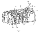
- Figure 1 of the accompanying drawings shows a typical gas turbine engine including two conventional wiring harnesses 102, 104, each provided with a respective connector component 106, 108 for connection to circuitry, which may be for example accommodated within the airframe of an aircraft in which the engine is installed.
- the harnesses 102, 104 are assembled from individual wires and cables which are held together over at least part of their lengths by suitable sleeving and/or braiding. Individual wires and cables, for example those indicated at 110, emerge from the sleeving or braiding to terminate at plug or socket connector components 112 for cooperation with complementary socket or plug connector components 114 on, or connected to, the respective electrical components.
- the conventional electrical harness has to be provided with plug or socket connector components 112 for connection to other electrical components, such as electrical units such as engine control units.
- plug or socket connector components add weight and complexity to the electrical harnesses.
- the conventional plug or socket connectors are exposed to the engine environment.
- the conventional plug or socket connectors may be exposed to, for example, high temperatures and/or vibrations.
- the exposed connectors therefore need to be particularly robust in order to survive this environment. This means that the conventional exposed connectors are bulky and heavy. Even such bulky and heavy connectors may still be susceptible to damage and/or becoming loose, for example due to engine vibration.
- Each conventional harness 102, 104 comprises a multitude of insulated wires and cables. This makes the conventional harness itself bulky, heavy and difficult to manipulate.
- the conventional harnesses occupy significant space within a gas turbine engine (for example within the nacelle of a gas turbine engine), and thus may compromise the design of the aircraft, for example the size and/or weight and/or shape of the nacelle.
- Conventional harnesses comprise a large number of components, including various individual wires and/or bundles of wires, supporting components (such as brackets or cables) and electrical and/or mechanical connectors. This can make the assembly process complicated (and thus susceptible to errors) and/or time consuming. Disassembly of the conventional harnesses (for example removal of the conventional harnesses from a gas turbine engine during maintenance) may also be complicated and/or time consuming. Thus, in many maintenance (or repair or overhaul) procedures on a gas turbine engine, removal and subsequent refitting of the conventional electrical harness may account for a very significant portion of the operation time and/or account for a significant proportion of the potential assembly errors.
- the electrical conductors in the conventional harnesses may be susceptible to mechanical damage.
- mechanical damage may occur during installation (for example through accidental piercing of the protective sleeves/braiding) and/or during service (for example due to vibration).
- the protective sleeves/braiding may need to be further reinforced, adding still further weight and reducing the ease with which they can be manipulated.
- the exposed electrical connectors used to connect one conductor to another conductor or conductors to electrical units may be susceptible to damage and/or may add significant weight to the engine.
- an electrical raft comprising a rigid material having multiple electrical conductors embedded therein.
- the electrical raft may, for example, be for a gas turbine engine.
- the electrical conductors may be used to transfer electrical signals around a gas turbine engine.
- the electrical raft also comprises an electrical connector for electrically connecting electrical conductors in the electrical raft to an electrical unit.
- the electrical connector comprises an embedded portion that is embedded in the rigid material.
- the electrical connector also comprises a contact portion, at least partially protruding from a surface of the rigid material.
- the contact portion is for electrically contacting a unit electrical connector on said electrical unit.
- the electrical connector also comprises a resiliently biased portion configured to bias the contact portion away from the embedded portion when the contact portion is moved towards the embedded portion.
- the resiliently biased portion may be, by way of example only, any type of spring.
- the resiliently biased portion may be provided between the embedded portion and the contact portion.
- the rigid material may be a rigid composite material, for example an organic matrix composite. Such a rigid composite material may be particularly stiff and/or lightweight.
- a rigid composite raft may be used that has suitable mechanical properties, whilst being thin and lightweight, for example compared with some other materials.
- the rigid composite material may comprise any suitable combination of resin and fibre as desired for a particular application.
- any of the resins and/or fibres described herein may be used to produce a rigid composite material for the electrical raft.
- Any suitable fibres may be used, for example carbon fibres, glass fibres, aramid fibres, and/or para-aramid fibres.
- the fibres may be of any type, such as woven and/or chopped.
- Any suitable resin may be used, for example epoxy, BMI (bismaleimide), PEEK (polyetheretherketone), PTFE (polytetraflouroethylene), PAEK (polyaryletherketone), polyurethane, and/or polyamides (such as nylon).
- BMI bismaleimide
- PEEK polyetheretherketone
- PTFE polytetraflouroethylene
- PAEK polyaryletherketone
- polyurethane polyurethane
- polyamides such as nylon
- the contact portion may be biased away from the surface of the rigid raft from which it protrudes by the resiliently biased portion.
- the electrical raft may be at least a part of an electrical harness for a gas turbine engine, and thus may be referred to herein as an electrical harness raft.
- the electrical conductors embedded in the rigid material may be used to transfer electrical signals around a gas turbine engine.
- Embedding electrical conductors in a rigid material has a great number of advantages over transferring electrical signals using a conventional harness, at least some of which are discussed herein.
- the electrical rafts may provide greater protection to the electrical conductors than a conventional harness.
- the rigid and/or hard material which may be a rigid and/or hard composite material
- the use of electrical rafts may reduce, or substantially eliminate, the chance of foreign bodies coming into contact with the electrical conductors, for example through fluid ingress.
- the electrical raft(s) may provide improved protection to the electrical conductors during manufacture/assembly of the raft/gas turbine installation, and/or during service/operation/maintenance of the gas turbine engine.
- an electrical connector (which may be referred to as a terminal) with a contact portion, a resiliently biased portion, and an embedded portion in the electrical raft.
- the electrical connector(s) which may be referred to as being integrated with, or integral to, the electrical raft, is/are protected by the rigid material of the raft and thus may be more reliable and less susceptible to damage. They may also be lighter and more compact, because no additional protection for the connectors may be required. Furthermore, because they may be assembled with the electrical raft, their position can be determined accurately, and not susceptible to error during connection to other units.
- the resilient bias provided by the resiliently biased portion may help to ensure that a robust electrical contact is maintained with connected electrical units throughout operation, for example in high vibration environments such as gas turbine engines.
- the electrical raft may comprise at least two substantially opposing electrical connectors forming a set of electrical connectors.
- the electrical raft may comprise at least two sets of opposing electrical connectors.
- the direction of the biasing force from the respective resiliently biased portion of the electrical connectors may be substantially opposite for two substantially opposing electrical connectors.
- the respective contact portions of two substantially opposing electrical connectors may be facing each other.
- Having a set of opposing electrical connectors in the electrical raft may help to ensure that a robust electrical contact is maintained between the electrical raft and a connected electrical unit, for example in a high vibration environment.
- opposing electrical connectors may be biased in opposite directions towards where the electrical connector of an electrical unit would be positioned when connected. In this way, movement of a connected electrical unit could be tolerated without loss of electrical contact.
- At least a part of the resiliently biased portion may be contained within the rigid material.
- some or all of the resiliently biased portion may be embedded in the rigid material, for example in an unbiased state. Accordingly, the resiliently biased portion, and any associated moving parts, may be protected from the surrounding environment by the rigid material. This may help to reduce the possibility of damage to the resiliently biased portion and/or increase its operational/service life, without having to provide dedicated protection.
- the electrical raft may comprise a mounting surface for mounting said electrical unit.
- the or each electrical connector of the electrical raft may be provided in a recess extending from the mounting surface into the rigid material. Providing the electrical connector(s) in a recess in the rigid material may provide further protection to the electrical connector(s). Additionally/alternatively, this may be a particularly convenient arrangement for allowing an electrical unit to be connected to the electrical raft, because the electrical unit could have an electrical connector arranged to protrude into the recess when the unit is mounted on the mounting surface of the electrical raft.
- the contact portion of the or each electrical connector may extend from the recess in a direction that is substantially parallel to the mounting surface.
- the resilient bias may act in a plane that is substantially parallel to the mounting surface.
- the contact portions of the electrical connectors may thus be biased into the recess. As explained elsewhere, this may be convenient for biasing the contact portions towards an electrical connector of an electrical unit that may be connected to the electrical raft.
- the electrical raft may comprise mounting portions for mechanically mounting an electrical unit to the electrical raft, the mounting portions being different separate from the or each electrical connector.
- the mounting portions may be provided at different, separate physical locations to the electrical connectors. In this way, the resiliently biased electrical connectors of the electrical raft may be substantially independent of the mechanical fixing, and thus the continuity of the electrical connection may be substantially independent of the accuracy of the mechanical fixing.
- At least one of the electrical conductors embedded in the electrical raft may be an electrically conductive wire.
- the or each electrically conductive wire may be surrounded by an electrically insulating sleeve.
- individual wires may be laid into (or embedded in) the electrical raft, and each wire may be used to transfer one or more electrical signals through the raft and around the engine.
- Providing a sleeve to the individual wires may provide extra mechanical and/or electrical protection/isolation.
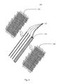
- At least some (for example a plurality) of the electrical conductors may be provided in a flexible printed circuit.
- at least some of the electrical conductors may be provided as electrically conductive tracks in a flexible substrate.
- the flexible printed circuit may be flexible before being embedded in the rigid material.
- Providing the electrical conductors as tracks in a flexible printed circuit may allow the size of the resulting electrical raft to be reduced further and/or substantially minimized. For example, many different electrical conductors may be laid into a flexible printed circuit in close proximity, thereby providing a compact structure.
- the flexible substrate of a single flexible printed circuit may provide electrical and/or mechanical protection/isolation to a large number of electrical conductors.
- Any given electrical raft may be provided with one or more electrical wires embedded therein (which may be sheathed) and/or one or more flexible printed circuits embedded therein. As such, a given electrical raft may have wires and flexible printed circuits laid therein.
- the embedded electrical conductors may be described as being fixed in position by the rigid material, for example relative to the rest of the electrical raft. It will also be appreciated that the embedded electrical conductors may be said to be surrounded by the rigid material and/or buried in the rigid material and/or integral with (or integrated into) the rigid material.
- an electrical raft assembly comprising an electrical raft including an electrical connector as described above and elsewhere herein.
- the electrical raft assembly also comprises an electrical unit mounted on the electrical raft.
- the electrical unit comprises a unit electrical connector that is in electrical contact with one or more of the or each electrical connector of the electrical raft.
- the electrical unit may be any sort of electrical unit that may be provided to a gas turbine engine.
- the electrical unit may be any type of electronic control unit (ECU), such as an Electronic Engine Controller (EEC) and an Engine Health Monitoring Unit (EMU).
- ECU Electronic Engine Controller
- EMU Engine Health Monitoring Unit
- the electrical unit may be a further electrical raft.
- electrical conductors in the ECUs may be connected to electrical conductors of the electrical raft via the electrical connectors in the electrical raft.
- At least one electrical unit may be attached to an electrical raft in an electrical raft assembly.
- Such an electrical raft assembly may be a particularly convenient, lightweight and/or compact way of providing (for example attaching, fixing or mounting) an electrical unit to the gas turbine engine.
- the electrical unit and the electrical raft (which may form at least a part of an electrical harness for the gas turbine engine) may be assembled together (mechanically and/or electrically) before being installed on the gas turbine engine, as described elsewhere herein.
- the biased electrical contact of the electrical raft may ensure that the electrical unit is robustly electrically attached to the electrical raft (and thus potentially to an extended electrical system of the gas turbine engine).
- the respective connectors may not be exposed to the region outside the electrical raft assembly. In other words, the respective connected electrical connectors may be contained within the electrical raft assembly. This may help to protect the connectors from damage and/or degradation.
- the electrical unit in the electrical raft assembly may comprise a mounting surface for mounting the electrical unit onto the electrical raft, for example onto a mounting surface of the electrical raft.
- the unit electrical connector may extend from the electrical unit into the electrical raft.
- the unit electrical connector may extend into a recess in the electrical raft, such as the recess described above, which may be formed in a mounting surface of the electrical raft. This may be a particularly convenient arrangement for ensuring that the electrical connectors are contained within the electrical raft assembly, and thus protected.
- the electrical raft and the electrical unit may be mechanically fixed together, for example using mechanical fixings that are independent of the electrical connectors.
- the engagement loading (for example provided by the biasing element) of the electrical contacts of the electrical raft and the electrical unit can be optimized for the electrical connection, and need not rely on or have to provide mechanical fixing.
- the tip of the (or each) unit electrical connector and the tips of the or each electrical connectors of the electrical raft may point in substantially perpendicular directions, for example when connected together in an electrical raft assembly. This may assist in maintaining a clean and robust electrical connection between the connectors.
- the contact portion of the or each electrical connector of the electrical raft may have a tapered cross-section (over at least a portion, for example over a tip portion of the contact portion), which may be shaped such that the contact portion is pushed against the resiliently biased portion by the unit electrical connector as the unit electrical connector is moved into position during assembly.
- the contact portion of the electrical connector of the electrical raft is contacted and pushed by the unit electrical connector, and thus the respective connectors may be wiped as they pass over each other. Again, this may help to ensure that the electrical connection is clean and robust.
- a gas turbine engine or gas turbine engine installation comprising an electrical raft and/or an electrical raft assembly as described above and elsewhere herein.
- at least one electrical raft and/or electrical raft assembly may be used as part of an electrical harness for transferring electrical signals around the engine, in the form of electrical harness raft(s) and/or electrical harness raft assemblies.
- the electrical raft assembly may be a first engine installation component, and the gas turbine engine may further comprise a second engine installation component having electrical conductors, the first and second engine installation components may be a part of an electrical system.
- the gas turbine engine (or the electrical system) may further comprise at least one flexible cable connected between the electrical raft assembly and the second engine installation component so as to electrically connect electrical conductors of the electrical raft assembly with electrical conductors of the second engine installation component.
- the second engine installation component may be, for example, an ECU, such as an EMU or EEC. Additionally or alternatively, the second engine installation component may be a further electrical raft or electrical raft assembly. The second engine installation component may or may not comprise an electrical connector, such as that provided to the first electrical component. Thus, the first and second engine installation components may form at least a part of an electrical harness raft. Such an electrical harness raft may comprise further electrical rafts and/or electrical harness raft assemblies and/or further flexible cable(s).
- Use of one or more electrical rafts may significantly reduce build time of an engine.
- use of electrical rafts may significantly reduce the part count involved in engine assembly compared with a conventional harness arrangement.
- the number and/or complexity of the operations required to assemble an engine (for example to assemble/install the electrical system (or network) and/or other peripheral components, which may be referred to in general as engine dressing) may be reduced.
- engine dressing For example, rather than having to install/assemble a great number of wires and/or wiring looms together on the engine installation, it may only be necessary to attach a relatively small number of electrical rafts/electrical raft assemblies, which themselves may be straightforward to handle, position, secure and connect. Connection between the rafts and other electrical components using the flexible cable(s) may be particularly convenient and straightforward.
- use of electrical rafts in a gas turbine installation may reduce assembly time and/or reduce the possibility of errors occurring during assembly.
- electrical rafts may provide significant advantages during maintenance, such as repair and overhaul. As discussed above, the electrical rafts may be particularly quick and straightforward to assemble. The same advantages discussed above in relation to assembly apply to disassembly/removal from the gas turbine engine. Thus, any repair/overhaul that requires removal of at least a part of the electrical harness may be simplified and/or speeded up through use of electrical rafts as at least a part of the electrical harness, for example compared with conventional harnesses.
- Use of electrical rafts (for example as part of one or more electrical raft assemblies) may allow maintenance procedures to be advantageously adapted. For example, some maintenance procedures may only require access to a certain portion of the gas turbine engine that only requires a part of the harness to be removed.
- the build/assembly times may be additionally or alternatively reduced by pre-assembling and/or pre-testing individual and/or combinations of electrical rafts prior to engine assembly. This may allow the electrical and/or mechanical operation of the electrical rafts to be proven before installation, thereby reducing/eliminating the testing required during engine installation.
- first and second rigid raft assemblies may comprise electrical rafts having electrical conductors embedded in a rigid material.
- the electrical conductors may be at least a part of an electrical system arranged to transfer electrical signals around the engine.
- the electrical rafts may be a particularly lightweight solution for transferring electrical signals around an engine.
- an electrical raft may be lighter, for example significantly lighter, than a conventional harness required to transmit a given number of electrical signals.
- a plurality of conductors may be embedded in a single electrical raft, whereas in a conventional arrangement a large number of heavy, bulky wires and/or insulating sleeves would be required.
- the reduced weight may be particularly advantageous, for example, when used on gas turbine engines on aircraft.
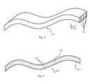
- Electrical rafts may be more easily packaged and/or more compact, for example than conventional harnesses. Indeed, the electrical rafts can be made into a very wide range of shapes as desired. This may be achieved, for example, by manufacturing the electrical rafts using a mould conforming to the desired shape. As such, each electrical raft may be shaped, for example, to turn through a tighter corner (or smaller bend radius) than a conventional harness.
- the electrical rafts may thus provide a particularly compact solution for transferring electrical signals around a gas turbine engine.
- the electrical rafts may be readily shaped to conform to neighbouring components/regions of a gas turbine engine, for example components/regions to which the particular electrical raft is attached, such as a fan casing or a core casing.
- the environment of a gas turbine engine during operation may be particularly severe, with, for example, high levels of vibration and/or differential expansion between components as the temperature changes through operation and as the components move relative to each other.
- Providing at least one flexible cable to connect an electrical raft to another component may allow the electrical rafts and/or components to accommodate vibration and/or relative movement, for example of the component(s)/assemblies to which they are attached/mounted during use.
- the flexible cable(s) used to electrically connect electrical raft(s) to other component(s) may have sufficient length to accommodate such vibration and/or movement during use.
- providing separate (for example more than one) electrical rafts and connecting at least some (for example at least two) of them together using at least one flexible cable may allow the electrical rafts to accommodate vibration and/or relative movement of the component(s)/assemblies to which they are attached/mounted during use.
- the electrical signals transferred by the conductors in the electrical raft, and around the engine using the electrical rafts/raft assemblies may take any form.
- the electrical signals may include, by way of non-limitative example, electrical power and/or electrical control/communication signals and/or any other type of transmission through an electrical conductor.
- Transmission of signals around the engine may mean transmission of signals between (to and/or from) any number of components/systems in the engine and/or components/system of a structure (such as an airframe) to which the gas turbine engine is (or is configured to be) connected/installed in.
- an electrical raft may be used to transfer/communicate any possible combination of electrical signals in any part of a gas turbine engine installation or a related (for example electrically and/or mechanically connected) structure/component/system.
- An electrical raft or raft assembly may be provided in any suitable location/position of the gas turbine engine.
- the gas turbine engine may comprise a bypass flow duct formed between an engine core and an engine fan casing (the gas turbine engine may be a turbofan engine, for example); and the electrical raft may form at least a part of a radially extending splitter (which may be referred to as a bifurcation) that extends across the bypass flow duct.
- a splitter electrical raft (which may be referred to as a splitter electrical raft) may provide an electrical connection between a fan casing and an engine core.
- An electrical raft may be provided with (for example have embedded therein) at least one additional electrical socket.
- the or each additional electrical socket may be in electrical contact with at least one of the respective electrical conductors embedded in the rigid material and may have terminals for connection with a complimentary connector.
- Such an additional electrical socket may take any suitable form, and may allow the electrical raft to be easily connected to other components, such as flexible cables and/or other electrical rafts.
- An electrical raft may, have components and/or parts of other systems embedded therein, such as fluid passages (or pipes) that may form a part of a fluid system, for example for carrying a gas (such as cooling air, sealing air, and/or muscle air (for example for pneumatic systems)) and/or a liquid (such as fuel, water, oil and/or hydraulic fluid).
- a gas such as cooling air, sealing air, and/or muscle air (for example for pneumatic systems)
- a liquid such as fuel, water, oil and/or hydraulic fluid
- a rigid raft assembly for a gas turbine engine
- the rigid raft assembly comprising a rigid material that carries at least a part of a first gas turbine engine system and at least a part of a second gas turbine engine system
- the first gas turbine engine system is a fluid system that comprises at least one fluid passage that is at least partially embedded in the rigid raft assembly.
- the second gas turbine engine system may be an electrical system that comprises electrical conductors at least partially embedded in the rigid material.
- the rigid raft assembly may be an electrical rigid raft assembly.
- An electrical raft may be mechanically and/or electrically connected to other components/systems of the gas turbine engine, for example ancillary, auxiliary or control components. Such other components/systems may be provided to an electrical raft in any suitable manner. For example, such other components/systems may be mounted on one or more electrical rafts. Thus, a surface of an electrical harness raft may be used as a mounting surface for other gas turbine engine components/systems, such as ancillary/auxiliary components/systems.
- An electrical raft may be provided with at least one mount on which other components (for example auxiliary/ancillary components/systems) of the gas turbine engine are (or may be) mounted.
- the mount may be a bracket, for example a bespoke bracket for the component/system mounted thereon or a conventional/standard bracket.
- the electrical raft may provide a stable, regular and convenient platform on which to mount the various systems/components.
- the combination of the installed electrical raft with components/systems mounted thereon may be much more compact and/or straightforward to assemble and/or have a greatly reduced number of component parts, for example compared with the corresponding conventional electrical harness and separately mounted components/systems.
- the mounts may be used to attach any component/system to an electrical raft (and thus to the engine) as required.
- fluid pipes for transferring fluid around the engine may be mounted to the electrical rafts (for example mechanically mounted using a bracket), and thus to the engine.
- the fluid pipes may be arranged to carry any fluid as desired, including gas (such as cooling air, sealing air, and/or muscle air (for example for pneumatic systems)) and/or liquid (such as fuel, water, oil and/or hydraulic fluid).
- gas such as cooling air, sealing air, and/or muscle air (for example for pneumatic systems)
- liquid such as fuel, water, oil and/or hydraulic fluid.
- more than one set of fluid pipes, for example for carrying different or the same fluids may be mounted on the same electrical raft.
- Examples of other components/systems that may be at least in part mounted to an electrical raft include, by way of non-limitative example: fire detectors and/or fire detection elements; thermocouples for measuring air temperature (for example within a particular engine zone); vibration monitoring processing equipment (for example a signal processing component/box containing electronics used to process a vibration signal that may be measured elsewhere in the engine); equipment for measuring fluid quality (for example a probe for oil debris monitoring may be provided to one or more pipes mounted to the raft, and/or a signal processing box for processing the oil quality measurements may be mounted on the box); and pressure sensors and/or signal processing equipment, for example for fluid pipes mounted on the rafts. At least some of these components/systems may form be electrically connected to the electrical conductors in the electrical raft using the electrical connector(s) of the electrical rafts.
- At least one electrical raft or raft assembly may be connected/attached/mounted to the gas turbine engine using at least one anti-vibration mount.
- an anti-vibration mount to attach the electrical raft/assembly to the gas turbine engine may reduce (or substantially eliminate) the amount (for example the amplitude and/or the number/range of frequencies) of vibration being passed to the electrical raft from the gas turbine engine, for example during use. This may help to prolong the life of the electrical raft.
- any other components that may be attached to the electrical raft may also benefit from being mounted to the gas turbine engine via the anti-vibration mounts, through being mounted on the electrical raft.
- the reduced vibration may help to preserve the electrical contact between the electrical raft and the electrical unit connected thereto.
- any components such as the electrical unit mounted to the electrical raft in an electrical raft assembly
- any components that would conventionally be mounted directly to the gas turbine engine and require at least a degree of vibration isolation no longer require their own dedicated anti-vibration mount.
- the total number of anti-vibration mounts that are required to assemble an engine may be reduced. This may reduce the number of parts required and the time taken to assemble an engine or engine installation and/or reduce the total assembled weight and/or reduce the likelihood of errors occurring during assembly.
- components that are conventionally mounted to an engine without anti-vibration mounts may benefit from vibration isolation without any weight/cost/assembly time penalty. This may reduce the possibility of damage occurring to such components and/or increase their service life.
- Such components may include, for example, ignitor boxes (used to provide high voltage power to engine ignitors), and pressure sensors/switches, for example for fluid systems such as oil, air, fuel, pneumatics and/or hydraulics.
- a method of assembling an electrical raft assembly as described above and elsewhere herein.
- the method comprises moving the electrical raft and the electrical unit together so that the unit electrical connector urges the contact portion of the or each electrical connector of the electrical raft against its respective resiliently biased portion.
- the resiliently biased portion provides a biasing force on the contact portion towards the unit electrical connector.
- the method may also comprise mechanically fixing the electrical raft and electrical unit together using fixings that are separate from the electrical connectors.
- the contact portion may be shaped (for example tapered) so as to move against its bias when a force is provided by the unit electrical connector moving into its connected position.
- the biasing force provided to the contact portion by the biasing portion may act in a direction that is substantially perpendicular to direction of relative movement of the respective connections of the electrical raft and the electrical unit during assembly.
- the electrical connectors of one or both of the electrical raft and the electrical unit may be cleaned, through a wiping action, during assembly.
- a ducted fan gas turbine engine generally indicated at 10 has a principal and rotational axis X-X.
- the engine 10 comprises, in axial flow series, an air intake 11, a propulsive fan 12, an intermediate pressure compressor 13, a high-pressure compressor 14, combustion equipment 15, a high-pressure turbine 16, and intermediate pressure turbine 17, a low-pressure turbine 18 and a core engine exhaust nozzle 19.
- the engine also has a bypass duct 22 and a bypass exhaust nozzle 23.
- the gas turbine engine 10 works in a conventional manner so that air entering the intake 11 is accelerated by the fan 12 to produce two air flows: a first air flow A into the intermediate pressure compressor 13 and a second air flow B which passes through the bypass duct 22 to provide propulsive thrust.
- the intermediate pressure compressor 13 compresses the air flow A directed into it before delivering that air to the high pressure compressor 14 where further compression takes place.
- the compressed air exhausted from the high-pressure compressor 14 is directed into the combustion equipment 15 where it is mixed with fuel and the mixture combusted.
- the resultant hot combustion products then expand through, and thereby drive the high, intermediate and low-pressure turbines 16, 17, 18 before being exhausted through the nozzle 19 to provide additional propulsive thrust.
- the high, intermediate and low-pressure turbines 16, 17, 18 respectively drive the high and intermediate pressure compressors 14, 13 and the fan 12 by suitable interconnecting shafts.
- the gas turbine engine 10 shown in Figure 2 comprises at least one electrical raft assembly 600 according to the present invention.
- the electrical raft assembly 600 comprises an electrical raft 200.
- the electrical raft 200 may be used to transmit/transfer electrical signals (or electricity, including electrical power and/or electrical control signals) around the engine and/or to/from the engine 10 from other components, such as components of an airframe.
- the function and/or construction of the electrical raft 200 and electrical raft assembly 600 may be as described above and elsewhere herein.
- the electrical raft 200 (which may be referred to herein simply as a raft 200 or an electrical harness raft 200) comprises at least one electrical conductor 252 embedded in a rigid material 220, which may be a rigid composite material.
- a rigid material 220 which may be a rigid composite material.
- the electrical raft 200 is provided with an electrical unit 300.
- the electrical raft 200 and the electrical unit 300 together form the electrical raft assembly 600.
- the electrical raft 200 (or the electrical raft assembly 600) may be provided with other gas turbine components/systems, such as fluid pipes or conduits forming at least a part of a fluid system.
- fluid pipes may be attached to the electrical raft 200 using mounting brackets. Additionally or alternatively, such fluid pipes may be embedded in the electrical raft 200.
- the electrical raft 200 (and/or electrical raft assembly 600) may be attached to the rest of the gas turbine engine 10 using mounts 400, which may be anti-vibration (AV) mounts configured to reduce or substantially eliminate vibration from components of the gas turbine engine 10 being passed to the electrical raft 200, and thus to any components/systems 300 mounted thereon/connected thereto.
- mounts 400 which may be anti-vibration (AV) mounts configured to reduce or substantially eliminate vibration from components of the gas turbine engine 10 being passed to the electrical raft 200, and thus to any components/systems 300 mounted thereon/connected thereto.
- AV anti-vibration
- FIG 3 is a more detailed view of the electrical raft assembly 600.
- the electrical raft 200 which forms part of the electrical raft assembly 600, comprises electrical connectors 700.
- the electrical connectors 700 allow the electrical raft 200 to be electrically connected to the electrical unit 300.
- one or more electrical connectors 700 are in electrical contact with one or more unit electrical connectors 800 of the electrical unit 300.
- circuits in the electrical unit 300 can be in communication with other components through an electrical raft 200, thereby allowing signals (for example control/communication signals) to be transferred between the electrical unit 300 other component/systems of the gas turbine engine 10 (and optionally to other components/parts to which the gas turbine engine 10 is attached).
- the Figure 3 embodiment has four electrical connectors 700, but different electrical rafts 200 in accordance with the invention may have different numbers of electrical connectors, for example 1, 2, 3, 5, 6, 7, 8, 9, 10 or more than 10 electrical connectors, some or all of which may be associated with (for example in electrical connection with) a single unit electrical connector 810.
- the Figure 3 embodiment has only one unit electrical connector 810, but other electrical raft assemblies 600 in accordance with the invention may have electrical units 300 that have more than one unit electrical connector 810, for example 2, 3, 4, 5 or more than 5 unit electrical connectors 810.
- Each (or at least one) connector 700 comprises an embedded portion 730, a contact portion 710, and a resiliently biased portion 720.
- the embedded portion 730 is at least partially embedded in the electrical raft 200. This may mean that the embedded portion 730 is immobile, or fixed, relative to the electrical raft 200.
- the embedded portion may be in electrical contact with the electrical conductors 252 embedded in the electrical raft 200 in any suitable manner.
- the embedded portion 730 may at least partially comprise a conductor, for example a metallic conductor, and may take any suitable form.
- the embedded portion 730 may simply be a fixed portion that is integral with the resiliently biased portion 720.
- the contact portion 710 at least partially protrudes from the rigid material 220 of the electrical raft 200.
- the contact portion 710 may be made from any suitable material, and may comprise any suitable conductive material, for example a metallic conductive material.
- the contact portion 710 is arranged to form an electrical connection with a unit electrical connector 800 of the electrical unit 300.
- the contact portion 710 has a tapered, or dome-like, cross-section. Other embodiments may have different shapes of contact portion depending, for example, on the unit electrical connector 800 with which they contact in use.
- the resiliently biased portion 720 provides a biasing force to the contact portion.
- the resiliently biased portion provides a biasing force towards a neutral position, i.e. if the contact portion 710 is moved away from its neutral position, the resiliently biased portion 720 provides a force to return the contact portion 710 to its neutral position.
- the neutral position may be a position in which the contact portion extends from the surface of the rigid material 220.
- the resiliently biased portion 720 may take any suitable form, for example any type of spring (such as a coil spring), and/or any suitable flexible member and/or any suitable compressible/elastic member.
- the resiliently biased portion 720 may be at least partially embedded in the rigid material 220.
- the resiliently biased portion 720 may comprise and/or accommodate an electrically conductive material.
- the resiliently biased portion 720 may comprise and/or be at least partially manufactured by a metallic conductor.
- each electrical conductor 700 extends into a recess 290 in the electrical raft 200.
- the recess 290 may be said to be formed in the rigid material 220 of the electrical raft 200.
- the recess 290 may be formed in a mounting surface 292 of the electrical raft 200.
- the mounting surface 292 may be the surface on which the electrical unit 300 is mounted. As such the mounting surface 292 may be in contact with a mounting surface 392 of the electrical unit 300 when the electrical unit 300 and the electrical raft 200 are connected together to form the electrical raft assembly 600.
- the unit electrical connector 800 when the electrical unit 300 and the electrical raft 200 are assembled together, the unit electrical connector 800 is pushed into the recess 290.
- the unit electrical connector 800 may extend in a direction that is perpendicular to the direction in which the electrical connector(s) 700 of the electrical raft 200 extend and/or to the direction of the biasing force provided by the biasing element 720.
- the direction of the biasing force may be substantially parallel to the mounting surface 292, as in the Figure 3 example.
- the unit electrical connector 800 (for example the tip 810 of the unit electrical connector 800) pushes the contact portion 710 towards, or into, the rigid material 220, against the resilient bias of the resiliently biased portion 720.
- the direction of the biasing force may be substantially perpendicular to the relative direction of movement of the electrical unit 300 and the electrical raft 200 during assembly.
- both the contact portion 710 and the unit electrical connector 800 may be wiped (i.e. they may wipe past each other), and thus may be cleaned. This may help to improve the electrical connection.
- the contact portion 710 of the electrical connector(s) 700 of the electrical raft 200 may be biased towards the unit electrical connector 800. This may help to ensure a robust electrical connection. For example, it may help to ensure that the electrical connection remains robust in the event of vibration.
- the electrical connection 700/800 may be substantially independent of the mechanical fixing 450 that holds the electrical raft 200 and the electrical unit 300 together. This may be advantageous, because it means that the engagement loading of the electrical contacts 700/800 may be substantially independent of the mechanical fixing. As such, the electrical connection may be substantially independent of the accuracy of the mechanical fixing 450. This may be at least in part due to the arrangement of the electrical connector 700 in the electrical raft 200, for example as a result of including the resiliently biased portion 720.
- the unit electrical connector 800 may have any suitable shape.
- the electrical connector(s) 700 of the electrical raft 200 may be shaped/positioned accordingly.
- the unit electrical connector 800 has a stepped shape.
- this stepped shaped may take the form of two axially separated, concentric cylindrical portions of different diameters.
- the distal cylindrical portion has a smaller diameter than the proximal cylindrical portion (distal and proximal being in relation to the body of the electrical unit 300).
- the different portions of the unit electrical connector 800 are contact by different electrical connectors 700.
- the electrical raft 200 in the Figure 3 arrangement has two sets of electrical connectors 700.
- Each set comprises two opposing electrical connectors 700, which have contact portions 710 that are provided with biasing forces in opposing directions by their respective biasing portions 720 when the unit electrical connector 800 is in place.
- a first set of electrical connectors 700 contact a distal end portion 810 of the unit electrical connector 800, and a second set of electrical connectors 700 contact a proximal end portion of the unit electrical connector 800.
- the connectors 700 in each set of electrical connectors may lie in the same plane as each other which may be parallel to the mounting plane 292. It is emphasized that the arrangement (for example number and positioning) of the electrical connectors 700 of the electrical raft 200, and of the unit electrical connector 800, in the Figure 3 arrangement is merely by way of example only. It will be recognized that a great many other arrangements fall within the scope of the invention.
- the electrical conductors 252 in the electrical raft 200 are themselves provided in a harness 250, which may be a flexible printed circuit board (or FPC) 250. Such an FPC is explained in greater detail elsewhere herein.
- FPC flexible printed circuit board
- the electrical conductors 252 embedded in the electrical raft 200 may be provided in any suitable way, for example as insulated or non-insulated wires or tracks laid directly into the rigid material 220.
- the electrical conductors 252 in Figure 3 may be connected to the electrical connector 700 in any suitable manner, for example directly connected or via linking conductor(s) 214 such as those shown in Figure 3 .
- FIG. 4 shows a perspective view of the FPC 250
- Figure 5 shows a side view.
- Such an FPC 250 may comprise a flexible (for example elastically deformable) substrate 255 with conductive tracks 252 laid/formed therein.
- the FPC 250 may thus be deformable.
- the FPC 250 may be described as a thin, elongate member and/or as a sheet-like member.
- Such a thin, elongate member may have a major surface defined by a length and a width, and a thickness normal to the major surface.
- the FPC 250 may extend along a length in the x-direction, a width in the y-direction, and a thickness (or depth or height) in the z-direction.
- the x-direction may be defined as the axial direction of the FPC.
- the x-direction (and thus the z-direction) may change along the length of the FPC 250 as the FPC is deformed.
- the x-y surface(s) ie the surfaces formed by the x and y directions
- the FPC 250 is deformable at least in the z direction, i.e. in a direction perpendicular to the major surface.
- FPCs may be additionally of alternatively deformable about any other direction, and/or may be twisted about any one or more of the x, y, or z directions.
- the flexible substrate 255 may be a dielectric.
- the substrate material may be, by way of example only, polyamide. As will be readily apparent, other suitable substrate material could alternatively be used.
- the conductive tracks 252 which may be surrounded by the substrate 255, may be formed using any suitable conductive material, such as, by way of example only, copper, copper alloy, tin-plated copper (or tin-plated copper alloy), silver-plated copper (or silver-plated copper alloy), nickel-plated copper (or nickel-plated copper alloy) although other materials could alternatively be used.
- the conductive tracks 252 may be used to conduct/transfer electrical signals (including electrical power and electrical control signals) through the rigid raft assembly (or assemblies) 200, for example around a gas turbine engine 10 and/or to/from components of a gas turbine engine and/or an airframe attached to a gas turbine engine.
- the size (for example the cross-sectional area) and/or the shape of the conductive tracks 252 may depend on the signal(s) to be transmitted through the particular conductive track 252. Thus, the shape and/or size of the individual conductive tracks 252 may or may not be uniform in a FPC 250.
- the example shown in Figures 4 and 5 has 6 conductive tracks 252 running through the substrate 255.
- the number of conductive tracks 252 running through a substrate 255 could be fewer than 6, or greater than 6.
- the number of conductive tracks 252 could be far greater than 6, for example tens or hundreds of tracks, as required.
- many electrical signals and/or power transmission lines may be incorporated into a single FPC 250.
- a single FPC 250 may comprise one layer of tracks, or more than one layer of tracks, for example, 2, 3, 4, 5, 6, 7, 8, 9, 10 or more than 10 layers of tracks.
- An FPC may comprise significantly more than 10 layers of tracks, for example at least an order of magnitude more layers of tracks.
- a layer of tracks may be defined as being a series of tracks that extend in the same x-y surface.
- the example shown in Figures 4 and 5 comprises 2 layers of tracks, with each layer comprising 3 tracks 252.
- an electrical raft 200 as described and claimed herein may be manufactured using any suitable method.
- the rigid material 220 may initially be provided as layers of flexible material, such as (by way of example only) layers of fibre and resin compound.
- This flexible material may be placed into a mould, for example having a desired shape.
- Other components such as fluid pipes 210 and/or the electrical conductors 252, which may be embedded in a FPC 250) may also be placed into the mould, for example between layers of the flexible material from which the rigid material 220 is ultimately formed.
- Parts of the mould may have any suitable form and/or construction, for example that could be readily removed when the electrical raft 200 is formed into the desired shape.
- Figure 6 shows components of an example of an electrical raft 200 prior to one method of construction.
- the electrical conductors 252 are provided between two layers of material 230, 240 that, after construction, form the rigid material 220. Some of the electrical conductors 252 are provided in an FPC 250.
- the material 230, 240 may be a fibre and resin compound, as described elsewhere herein. Such a fibre and resin compound may, after suitable treatment (for example heat treatment), produce the rigid composite material 220.
- the fibre and resin compound is formed of a sheet of interwoven fibres, or strands.
- the strands in Figure 6 extend in perpendicular directions, although the strands may extend in any one or more directions as required.
- the strands/fibres may be pre-impregnated (or "pre-pregged") with the resin.
- both the first and second layers 230, 240 and the electrical conductors 252 may be flexible, for example supple, pliable or malleable. As such, when the layers 230, 240 and the electrical conductors 252 are placed together, they may be moulded, or formed, into any desired shape. For example, the layers 230, 240 and the electrical conductors 252 may be placed into a mould (which may be of any suitable form, such as a glass or an aluminium mould) having the desired shape.
- the desired shape may be, for example, a shape that corresponds to (for example is offset from) a part of a gas turbine engine, such as, by way of example only, at least a part of a casing, such as an engine fan casing or engine core casing. This may enable the final raft to adopt shapes that are curved in two-dimensions or three-dimensions.
- any suitable method could be used to produce the electrical raft 200.
- the strands/fibres need not be pre-impregnated with the resin.
- the fibres/strands could be put into position (for example relative to electrical conductors 252/FPC 250) in a dry state, and then the resin could be fed (or pumped) into the mould.
- Such a process may be referred to as a resin transfer method. Indeed, in some constructions no fibre may be used at all in the rigid material 220.
- the electrical raft 200 may be set in the desired shape.
- the electrical connectors 700 may be provided to the electrical raft 200 at any suitable time during manufacture, for example prior to any stiffening treatment of the rigid raft assembly 200, or after such treatment.
- the or each connector 700 may be fixed (for example bonded) into an appropriate recess in the electrical raft.
- Such a recess may be formed using a correspondingly shaped mould, or may be formed (for example by machining or boring) after the rigid electrical raft is set.
- the embedded portion 730 of the each connector 700 may be electrically connected to one or more embedded conductors 252 at this stage.
- the electrical connector(s) 700 may be embedded directly into the electrical raft 200 during the forming and setting of the electrical raft 200.
- the rigid material 220 may set around the electrical connector(s) 700, thereby fixing them into position.
- the electrical conductors 252 may be in electrical contact with the electrical connector(s) 700 prior to the rigid material 220 being set around them.
- Figure 7 is a schematic showing a cross-section perpendicular to the direction X-X of a gas turbine engine comprising electrical rafts 200A-200G.
- Figure 7 shows seven electrical rafts 200A-200G (which may be referred to collectively as electrical rafts 200).
- Three of the electrical rafts 200A, 200C, 200E have at least one electrical unit 300 mounted thereon to form an electrical raft assembly 600.
- These three electrical rafts 200A, 200C, 200E and/or the electrical raft assemblies 600 shown in Figure 7 may thus be as described elsewhere herein, for example in relation to Figures 2-6 .
- the electrical raft assemblies 600 shown in Figure 7 may comprise electrical connectors 700/800, and components thereof, described in greater detail elsewhere.
- any one or more of the electrical rafts 200A-200G may have an electrical unit 300 mounted thereon to form an electrical raft assembly 600.
- Each of the electrical rafts 200A-200G shown in Figure 7 comprises one or more electrical conductors 252 as described elsewhere herein. However, any one or more of the electrical rafts 200A-200G may be replaced with a raft that does not comprise electrical conductors 252.
- Such a raft would not be an electrical raft 200, but may otherwise be as described elsewhere herein, for example it may be a rigid raft that may have components/systems (such as, by way of example only, fluid systems, such as pipes) mounted thereon and/or embedded therein.
- a gas turbine engine in accordance with the present invention may have a combination of electrical rafts 200 and non-electrical rafts.
- electrical rafts 200A-200G shown in Figure 7 is by way of example only. Alternative arrangements, for example in terms of number, size, shape and/or positioning, of electrical rafts 200A-200G may be used. For example, there need not be 7 electrical rafts, the rafts may or may not be connected together, and the rafts could be provided to (for example mounted on) any one or more components of the gas turbine engine. Purely by way of example only, connection between electrical rafts 200A, 200B, 200C, 200D mounted on the fan casing 24 to the electrical rafts 200F, 200G mounted on the core casing 28 may be provided at least in part by means other than an additional electrical raft 200E, for example using wire conductors with insulating sleeves.
- one or more electrical rafts 200 may additionally or alternatively be provided to the nose cone, structural frames or elements within the engine (such as "A-frames"), the nacelle, the fan cowl doors, and/or any connector or mount between the gas turbine engine 10 and a connected structure (which may be at least a part of a structure in which the gas turbine engine 10 is installed), such as the pylon 500 between the gas turbine engine 10 and an airframe (not shown).
- A-frames structural frames or elements within the engine
- the nacelle such as "A-frames”
- the fan cowl doors such as any connector or mount between the gas turbine engine 10 and a connected structure (which may be at least a part of a structure in which the gas turbine engine 10 is installed), such as the pylon 500 between the gas turbine engine 10 and an airframe (not shown).
- any one or more of the electrical rafts 200A-200G may have a fluid passage 210 embedded therein.
- the fluid passage 210 may be part of a fluid system, such as a gas (for example pneumatic or cooling gas/air) and/or liquid (for example a fuel, hydraulic and/or lubricant liquid).
- a gas for example pneumatic or cooling gas/air
- liquid for example a fuel, hydraulic and/or lubricant liquid
- three of the electrical rafts 200A, 200B, 200C comprise a fluid passage 210 at least partially embedded therein.
- the electrical raft 200C also has a fluid passage (which may be for any fluid, such as those listed above in relation to embedded passage 210) mounted thereon.
- a mounted fluid passage 285 may be provided to any electrical raft, such as the electrical rafts 200A-200G shown in Figure 7 .
- the fluid passages 210, 285 shown in Figure 7 may be oriented in an axial direction of the engine 10. However, fluid passages may be oriented
- any electrical raft 200 may be provided with and/or may comprise (for example may have mounted on and/or have at least partially embedded therein) at least a part of any component and/or system of a gas turbine engine.
- Components/systems provided to different rafts 200 may be connected to each other, for example a component mounted on one raft 200 may be connected (for example directly electrically, mechanically and/or fluidly connected) to one or more components mounted on another raft 200.
- the electrical rafts 200A-200G may be attached to the rest of the gas turbine engine 10 in any suitable manner.
- mounts 400 which may be anti-vibration mounts, may be used.
- anti-vibration mounts 400 may, for example, allow all components of the electrical raft 200 and/or electrical raft assembly 600 to be isolated from vibrations.
- components of at least two gas turbine engine systems may be vibration isolated using a single set of anti-vibration mounts 400.
- the electrical rafts 200A-200D are mounted to a fan case 24 in the example of Figure 7 .
- electrical rafts such as those described by way of example herein may be provided/mounted anywhere on the engine 10.
- one or more electrical rafts 200F, 200G may be mounted between an engine core casing 28 and an engine core fairing 26.
- one or more electrical raft 200E may be provided as at least a part of (for example in) a passage across the bypass duct 22, such as a bifurcation or splitter.
- the electrical rafts mounted anywhere on the engine may be as described elsewhere herein, or otherwise in accordance with the invention.
- any of the electrical rafts 200A-200G may have any combination of mechanical, electrical and/or fluid connections to one or more (for example 2, 3, 4, 5 or more than 5) other components/systems of the gas turbine engine 10 and/or the rest of the gas turbine engine 10 itself. Examples of such connections are shown in Figure 7 , and described below, but it will be appreciated that a gas turbine engine 10 including electrical rafts 200 may have connections that are different to those show in Figure 7 .
- electrical rafts 200 (and/or non-electrical rafts) may be connected together (or to other components) using any combination of electrical, fluid and/or mechanical connectors.
- any of the electrical connections 290A/290B, 291-297 shown in Figure 7 may be any combination of electrical, fluid and/or mechanical connection.
- electrical rafts and/or non-electrical rafts may have no connection to other rafts or components.
- connection 291 is shown between the electrical rafts 200A and 200D.
- the connection 291 may comprise an electrical connection.
- Such an electrical connection may be flexible and may, for example, take the form of a flexible printed circuit such as the flexible printed circuit 250 shown in Figures 4 and 5 .
- Such a flexible electrical connection may be used to electrically connect any electrical raft 200 to any other component, such as another electrical raft 200.
- a connection 297 (which may be or comprise an electrical connection) is provided between the electrical raft 200A and a part of an airframe, or airframe installation 500, which may, for example, be a pylon.
- a fluid and/or mechanical connection 296 may additionally or alternatively be provided between the airframe 500 and another electrical raft 200C.
- other electrical and/or fluid connections 292, 293, 294, 295 may be provided between electrical rafts and other components, such as other electrical rafts.
- a direct connection 290A, 290B is provided between the electrical rafts 200B and 200C in the Figure 7 arrangement.
- Such a direct connection 290A, 290B may comprise a connector 290A provided on (for example embedded in) one electrical raft 200C connected to a complimentary connector 290B provided on (for example embedded in) another electrical raft 200B.
- Such a direct connection 290A, 290B may, for example, provide fluid and/or electrical connection between the two electrical rafts 200B, 200C.
- gas turbine engine may include a gas turbine engine/gas turbine engine installation and optionally any peripheral components to which the gas turbine engine may be connected to or interact with and/or any connections/interfaces with surrounding components, which may include, for example, an airframe and/or components thereof.
- connections with an airframe which are encompassed by the term 'gas turbine engine' as used herein, include, but are not limited to, pylons and mountings and their respective connections.
- the gas turbine engine itself may be any type of gas turbine engine, including, but not limited to, a turbofan (bypass) gas turbine engine, turbojet, turboprop, ramjet, scramjet or open rotor gas turbine engine, and for any application, for example aircraft, industrial, and marine application.
- Electrical rafts 200 such as any of those described and/or claimed herein may be used as part of any apparatus, such as any vehicle, including land, sea, air and space vehicles, such as motor vehicles (including cars and busses), trains, boats, submarines, aircraft (including aeroplanes and helicopters) and spacecraft (including satellites and launch vehicles).
- electrical rafts 200 and gas turbine engines 10 comprising electrical rafts 200 may fall within the scope of the invention.
- alternative arrangements of electrical rafts 200 for example in terms of the arrangement, including number/shape/positioning/constructions, of electrical connectors 700, the arrangement/shape/positioning/construction of the electrical rafts 200, the type and/or positioning of components (if any) mounted to/embedded in the electrical rafts 200, the rigid material 220 and the electrical conductors 252
- components if any mounted to/embedded in the electrical rafts 200, the rigid material 220 and the electrical conductors 252
Abstract
Description
- This invention relates to connecting electrical units. In particular, aspects of the invention relate to connectors between rigid electrical rafts used to distribute electrical signals around a gas turbine engine, and electrical units mounted on the rigid electrical rafts.
- A typical gas turbine engine has a substantial number of electrical components which serve, for example, to sense operating parameters of the engine and/or to control actuators which operate devices in the engine. Such devices may, for example, control fuel flow, variable vanes and air bleed valves. The actuators may themselves be electrically powered, although some may be pneumatically or hydraulically powered, but controlled by electrical signals.
- Electrical power, and signals to and from the individual electrical components, are commonly transmitted along conductors. Conventionally, such conductors may be in the form of wires and/or cables which are assembled together in a harness. In such a conventional harness, each wire may be surrounded by an insulating sleeve, which may be braided or have a braided cover.
- By way of example,
Figure 1 of the accompanying drawings shows a typical gas turbine engine including twoconventional wiring harnesses respective connector component - The
harnesses socket connector components 112 for cooperation with complementary socket orplug connector components 114 on, or connected to, the respective electrical components. - Thus the conventional electrical harness has to be provided with plug or
socket connector components 112 for connection to other electrical components, such as electrical units such as engine control units. These conventional plug or socket connector components add weight and complexity to the electrical harnesses. Furthermore, the conventional plug or socket connectors are exposed to the engine environment. Thus, the conventional plug or socket connectors may be exposed to, for example, high temperatures and/or vibrations. The exposed connectors therefore need to be particularly robust in order to survive this environment. This means that the conventional exposed connectors are bulky and heavy. Even such bulky and heavy connectors may still be susceptible to damage and/or becoming loose, for example due to engine vibration. - Each
conventional harness - Conventional harnesses comprise a large number of components, including various individual wires and/or bundles of wires, supporting components (such as brackets or cables) and electrical and/or mechanical connectors. This can make the assembly process complicated (and thus susceptible to errors) and/or time consuming. Disassembly of the conventional harnesses (for example removal of the conventional harnesses from a gas turbine engine during maintenance) may also be complicated and/or time consuming. Thus, in many maintenance (or repair or overhaul) procedures on a gas turbine engine, removal and subsequent refitting of the conventional electrical harness may account for a very significant portion of the operation time and/or account for a significant proportion of the potential assembly errors.
- The electrical conductors in the conventional harnesses may be susceptible to mechanical damage. For example, mechanical damage may occur during installation (for example through accidental piercing of the protective sleeves/braiding) and/or during service (for example due to vibration). In order to reduce the likelihood of damage to the conductors in a conventional harness, the protective sleeves/braiding may need to be further reinforced, adding still further weight and reducing the ease with which they can be manipulated. Similarly, the exposed electrical connectors used to connect one conductor to another conductor or conductors to electrical units may be susceptible to damage and/or may add significant weight to the engine.
- According to an aspect of the invention, there is provided an electrical raft comprising a rigid material having multiple electrical conductors embedded therein. The electrical raft may, for example, be for a gas turbine engine. The electrical conductors may be used to transfer electrical signals around a gas turbine engine. The electrical raft also comprises an electrical connector for electrically connecting electrical conductors in the electrical raft to an electrical unit. The electrical connector comprises an embedded portion that is embedded in the rigid material. The electrical connector also comprises a contact portion, at least partially protruding from a surface of the rigid material. The contact portion is for electrically contacting a unit electrical connector on said electrical unit. The electrical connector also comprises a resiliently biased portion configured to bias the contact portion away from the embedded portion when the contact portion is moved towards the embedded portion.
- The resiliently biased portion may be, by way of example only, any type of spring. The resiliently biased portion may be provided between the embedded portion and the contact portion.
- Any suitable material may be used for the rigid material. For example, the rigid material may be a rigid composite material, for example an organic matrix composite. Such a rigid composite material may be particularly stiff and/or lightweight. Thus, a rigid composite raft may be used that has suitable mechanical properties, whilst being thin and lightweight, for example compared with some other materials. The rigid composite material may comprise any suitable combination of resin and fibre as desired for a particular application. For example, any of the resins and/or fibres described herein may be used to produce a rigid composite material for the electrical raft. Any suitable fibres may be used, for example carbon fibres, glass fibres, aramid fibres, and/or para-aramid fibres. The fibres may be of any type, such as woven and/or chopped. Any suitable resin may be used, for example epoxy, BMI (bismaleimide), PEEK (polyetheretherketone), PTFE (polytetraflouroethylene), PAEK (polyaryletherketone), polyurethane, and/or polyamides (such as nylon).
- The contact portion may be biased away from the surface of the rigid raft from which it protrudes by the resiliently biased portion. The electrical raft may be at least a part of an electrical harness for a gas turbine engine, and thus may be referred to herein as an electrical harness raft.
- The electrical conductors embedded in the rigid material may be used to transfer electrical signals around a gas turbine engine. Embedding electrical conductors in a rigid material (to create an electrical raft) has a great number of advantages over transferring electrical signals using a conventional harness, at least some of which are discussed herein.
- The electrical rafts may provide greater protection to the electrical conductors than a conventional harness. For example, the rigid and/or hard material (which may be a rigid and/or hard composite material) in which the conductors are embedded may provide greater protection (for example greater mechanical protection) to the embedded conductors, for example due to being resistant to breaking and/or snapping and/or piercing and/or puncturing. Purely by way of example, the use of electrical rafts may reduce, or substantially eliminate, the chance of foreign bodies coming into contact with the electrical conductors, for example through fluid ingress. The electrical raft(s) may provide improved protection to the electrical conductors during manufacture/assembly of the raft/gas turbine installation, and/or during service/operation/maintenance of the gas turbine engine. This may result in lower maintenance costs, for example due to fewer damaged components requiring replacement/repair and/or due to the possibility of extending time intervals (or service intervals) between inspecting the electrical system, for example compared with a system using only conventional harnesses.
- Further advantages are provided by including an electrical connector (which may be referred to as a terminal) with a contact portion, a resiliently biased portion, and an embedded portion in the electrical raft. The electrical connector(s), which may be referred to as being integrated with, or integral to, the electrical raft, is/are protected by the rigid material of the raft and thus may be more reliable and less susceptible to damage. They may also be lighter and more compact, because no additional protection for the connectors may be required. Furthermore, because they may be assembled with the electrical raft, their position can be determined accurately, and not susceptible to error during connection to other units. The resilient bias provided by the resiliently biased portion may help to ensure that a robust electrical contact is maintained with connected electrical units throughout operation, for example in high vibration environments such as gas turbine engines.
- The electrical raft may comprise at least two substantially opposing electrical connectors forming a set of electrical connectors. The electrical raft may comprise at least two sets of opposing electrical connectors. The direction of the biasing force from the respective resiliently biased portion of the electrical connectors may be substantially opposite for two substantially opposing electrical connectors. The respective contact portions of two substantially opposing electrical connectors may be facing each other.
- Having a set of opposing electrical connectors in the electrical raft may help to ensure that a robust electrical contact is maintained between the electrical raft and a connected electrical unit, for example in a high vibration environment. For example, opposing electrical connectors may be biased in opposite directions towards where the electrical connector of an electrical unit would be positioned when connected. In this way, movement of a connected electrical unit could be tolerated without loss of electrical contact.
- At least a part of the resiliently biased portion may be contained within the rigid material. For example, some or all of the resiliently biased portion may be embedded in the rigid material, for example in an unbiased state. Accordingly, the resiliently biased portion, and any associated moving parts, may be protected from the surrounding environment by the rigid material. This may help to reduce the possibility of damage to the resiliently biased portion and/or increase its operational/service life, without having to provide dedicated protection.
- The electrical raft may comprise a mounting surface for mounting said electrical unit. The or each electrical connector of the electrical raft may be provided in a recess extending from the mounting surface into the rigid material. Providing the electrical connector(s) in a recess in the rigid material may provide further protection to the electrical connector(s). Additionally/alternatively, this may be a particularly convenient arrangement for allowing an electrical unit to be connected to the electrical raft, because the electrical unit could have an electrical connector arranged to protrude into the recess when the unit is mounted on the mounting surface of the electrical raft.
- The contact portion of the or each electrical connector may extend from the recess in a direction that is substantially parallel to the mounting surface. The resilient bias may act in a plane that is substantially parallel to the mounting surface. The contact portions of the electrical connectors may thus be biased into the recess. As explained elsewhere, this may be convenient for biasing the contact portions towards an electrical connector of an electrical unit that may be connected to the electrical raft.
- The electrical raft may comprise mounting portions for mechanically mounting an electrical unit to the electrical raft, the mounting portions being different separate from the or each electrical connector. The mounting portions may be provided at different, separate physical locations to the electrical connectors. In this way, the resiliently biased electrical connectors of the electrical raft may be substantially independent of the mechanical fixing, and thus the continuity of the electrical connection may be substantially independent of the accuracy of the mechanical fixing.
- At least one of the electrical conductors embedded in the electrical raft may be an electrically conductive wire. The or each electrically conductive wire may be surrounded by an electrically insulating sleeve. As such, individual wires may be laid into (or embedded in) the electrical raft, and each wire may be used to transfer one or more electrical signals through the raft and around the engine. Providing a sleeve to the individual wires may provide extra mechanical and/or electrical protection/isolation.
- At least some (for example a plurality) of the electrical conductors may be provided in a flexible printed circuit. Thus, at least some of the electrical conductors may be provided as electrically conductive tracks in a flexible substrate. The flexible printed circuit may be flexible before being embedded in the rigid material.
- Providing the electrical conductors as tracks in a flexible printed circuit may allow the size of the resulting electrical raft to be reduced further and/or substantially minimized. For example, many different electrical conductors may be laid into a flexible printed circuit in close proximity, thereby providing a compact structure. The flexible substrate of a single flexible printed circuit may provide electrical and/or mechanical protection/isolation to a large number of electrical conductors.
- Any given electrical raft may be provided with one or more electrical wires embedded therein (which may be sheathed) and/or one or more flexible printed circuits embedded therein. As such, a given electrical raft may have wires and flexible printed circuits laid therein.
- It will be appreciated that the embedded electrical conductors (whether they are provided as embedded electrical wires or as conductive tracks in a flexible printed circuit embedded in the rigid material) may be described as being fixed in position by the rigid material, for example relative to the rest of the electrical raft. It will also be appreciated that the embedded electrical conductors may be said to be surrounded by the rigid material and/or buried in the rigid material and/or integral with (or integrated into) the rigid material.
- According to an aspect of the invention, there is provided an electrical raft assembly. The electrical raft assembly comprises an electrical raft including an electrical connector as described above and elsewhere herein. The electrical raft assembly also comprises an electrical unit mounted on the electrical raft. The electrical unit comprises a unit electrical connector that is in electrical contact with one or more of the or each electrical connector of the electrical raft.
- The electrical unit may be any sort of electrical unit that may be provided to a gas turbine engine. For example, the electrical unit may be any type of electronic control unit (ECU), such as an Electronic Engine Controller (EEC) and an Engine Health Monitoring Unit (EMU). In some cases, the electrical unit may be a further electrical raft. Thus electrical conductors in the ECUs may be connected to electrical conductors of the electrical raft via the electrical connectors in the electrical raft. At least one electrical unit may be attached to an electrical raft in an electrical raft assembly.
- Such an electrical raft assembly may be a particularly convenient, lightweight and/or compact way of providing (for example attaching, fixing or mounting) an electrical unit to the gas turbine engine. For example, the electrical unit and the electrical raft (which may form at least a part of an electrical harness for the gas turbine engine) may be assembled together (mechanically and/or electrically) before being installed on the gas turbine engine, as described elsewhere herein. The biased electrical contact of the electrical raft may ensure that the electrical unit is robustly electrically attached to the electrical raft (and thus potentially to an extended electrical system of the gas turbine engine). When the electrical unit is attached to the electrical raft, the respective connectors may not be exposed to the region outside the electrical raft assembly. In other words, the respective connected electrical connectors may be contained within the electrical raft assembly. This may help to protect the connectors from damage and/or degradation.
- The electrical unit in the electrical raft assembly may comprise a mounting surface for mounting the electrical unit onto the electrical raft, for example onto a mounting surface of the electrical raft. The unit electrical connector may extend from the electrical unit into the electrical raft. For example, the unit electrical connector may extend into a recess in the electrical raft, such as the recess described above, which may be formed in a mounting surface of the electrical raft. This may be a particularly convenient arrangement for ensuring that the electrical connectors are contained within the electrical raft assembly, and thus protected.
- The electrical raft and the electrical unit may be mechanically fixed together, for example using mechanical fixings that are independent of the electrical connectors. In this way, the engagement loading (for example provided by the biasing element) of the electrical contacts of the electrical raft and the electrical unit can be optimized for the electrical connection, and need not rely on or have to provide mechanical fixing.
- The tip of the (or each) unit electrical connector and the tips of the or each electrical connectors of the electrical raft may point in substantially perpendicular directions, for example when connected together in an electrical raft assembly. This may assist in maintaining a clean and robust electrical connection between the connectors.
- The contact portion of the or each electrical connector of the electrical raft may have a tapered cross-section (over at least a portion, for example over a tip portion of the contact portion), which may be shaped such that the contact portion is pushed against the resiliently biased portion by the unit electrical connector as the unit electrical connector is moved into position during assembly. According to this arrangement, the contact portion of the electrical connector of the electrical raft is contacted and pushed by the unit electrical connector, and thus the respective connectors may be wiped as they pass over each other. Again, this may help to ensure that the electrical connection is clean and robust.
- According to an aspect of the invention, there is provided a gas turbine engine or gas turbine engine installation (for example for an airframe) comprising an electrical raft and/or an electrical raft assembly as described above and elsewhere herein. For example, at least one electrical raft and/or electrical raft assembly may be used as part of an electrical harness for transferring electrical signals around the engine, in the form of electrical harness raft(s) and/or electrical harness raft assemblies.
- In such a gas turbine engine according to an aspect of the present invention, the electrical raft assembly may be a first engine installation component, and the gas turbine engine may further comprise a second engine installation component having electrical conductors, the first and second engine installation components may be a part of an electrical system. The gas turbine engine (or the electrical system) may further comprise at least one flexible cable connected between the electrical raft assembly and the second engine installation component so as to electrically connect electrical conductors of the electrical raft assembly with electrical conductors of the second engine installation component.
- The second engine installation component may be, for example, an ECU, such as an EMU or EEC. Additionally or alternatively, the second engine installation component may be a further electrical raft or electrical raft assembly. The second engine installation component may or may not comprise an electrical connector, such as that provided to the first electrical component. Thus, the first and second engine installation components may form at least a part of an electrical harness raft. Such an electrical harness raft may comprise further electrical rafts and/or electrical harness raft assemblies and/or further flexible cable(s).
- Use of one or more electrical rafts may significantly reduce build time of an engine. For example, use of electrical rafts may significantly reduce the part count involved in engine assembly compared with a conventional harness arrangement. The number and/or complexity of the operations required to assemble an engine (for example to assemble/install the electrical system (or network) and/or other peripheral components, which may be referred to in general as engine dressing) may be reduced. For example, rather than having to install/assemble a great number of wires and/or wiring looms together on the engine installation, it may only be necessary to attach a relatively small number of electrical rafts/electrical raft assemblies, which themselves may be straightforward to handle, position, secure and connect. Connection between the rafts and other electrical components using the flexible cable(s) may be particularly convenient and straightforward. Thus, use of electrical rafts in a gas turbine installation may reduce assembly time and/or reduce the possibility of errors occurring during assembly.
- Use of electrical rafts may provide significant advantages during maintenance, such as repair and overhaul. As discussed above, the electrical rafts may be particularly quick and straightforward to assemble. The same advantages discussed above in relation to assembly apply to disassembly/removal from the gas turbine engine. Thus, any repair/overhaul that requires removal of at least a part of the electrical harness may be simplified and/or speeded up through use of electrical rafts as at least a part of the electrical harness, for example compared with conventional harnesses. Use of electrical rafts (for example as part of one or more electrical raft assemblies) may allow maintenance procedures to be advantageously adapted. For example, some maintenance procedures may only require access to a certain portion of the gas turbine engine that only requires a part of the harness to be removed. It may be difficult and/or time consuming, or not even possible, to only remove the required part of a conventional harness from a gas turbine engine. However, it may be relatively straightforward to only remove the relevant electrical raft, for example by simply disconnecting it from the engine and any other electrical rafts/components to which it is connected. Decreasing maintenance times has the advantage of, for example, reducing out-of service times (for example off-wing times for engines that are used on aircraft).
- The build/assembly times may be additionally or alternatively reduced by pre-assembling and/or pre-testing individual and/or combinations of electrical rafts prior to engine assembly. This may allow the electrical and/or mechanical operation of the electrical rafts to be proven before installation, thereby reducing/eliminating the testing required during engine installation.
- Accordingly, there is provided (and aspects of the invention may be used with/as a part of) a method of servicing a gas turbine engine, the method comprising: removing a first rigid raft assembly from the gas turbine engine, the rigid raft assembly incorporating at least a part of at least one component or system of the gas turbine engine; and installing a second, pre-prepared, rigid raft assembly onto the gas turbine engine in place of the first raft assembly. The first and second rigid raft assemblies may comprise electrical rafts having electrical conductors embedded in a rigid material. The electrical conductors may be at least a part of an electrical system arranged to transfer electrical signals around the engine.
- The electrical rafts may be a particularly lightweight solution for transferring electrical signals around an engine. For example, an electrical raft may be lighter, for example significantly lighter, than a conventional harness required to transmit a given number of electrical signals. A plurality of conductors may be embedded in a single electrical raft, whereas in a conventional arrangement a large number of heavy, bulky wires and/or insulating sleeves would be required. The reduced weight may be particularly advantageous, for example, when used on gas turbine engines on aircraft.
- Electrical rafts may be more easily packaged and/or more compact, for example than conventional harnesses. Indeed, the electrical rafts can be made into a very wide range of shapes as desired. This may be achieved, for example, by manufacturing the electrical rafts using a mould conforming to the desired shape. As such, each electrical raft may be shaped, for example, to turn through a tighter corner (or smaller bend radius) than a conventional harness. The electrical rafts may thus provide a particularly compact solution for transferring electrical signals around a gas turbine engine. The electrical rafts may be readily shaped to conform to neighbouring components/regions of a gas turbine engine, for example components/regions to which the particular electrical raft is attached, such as a fan casing or a core casing.
- The environment of a gas turbine engine during operation may be particularly severe, with, for example, high levels of vibration and/or differential expansion between components as the temperature changes through operation and as the components move relative to each other. Providing at least one flexible cable to connect an electrical raft to another component may allow the electrical rafts and/or components to accommodate vibration and/or relative movement, for example of the component(s)/assemblies to which they are attached/mounted during use. For example, the flexible cable(s) used to electrically connect electrical raft(s) to other component(s) may have sufficient length to accommodate such vibration and/or movement during use.
- For example, providing separate (for example more than one) electrical rafts and connecting at least some (for example at least two) of them together using at least one flexible cable may allow the electrical rafts to accommodate vibration and/or relative movement of the component(s)/assemblies to which they are attached/mounted during use.
- It will be appreciated that the electrical signals transferred by the conductors in the electrical raft, and around the engine using the electrical rafts/raft assemblies may take any form. For example, the electrical signals may include, by way of non-limitative example, electrical power and/or electrical control/communication signals and/or any other type of transmission through an electrical conductor. Transmission of signals around the engine may mean transmission of signals between (to and/or from) any number of components/systems in the engine and/or components/system of a structure (such as an airframe) to which the gas turbine engine is (or is configured to be) connected/installed in. In other words, an electrical raft may be used to transfer/communicate any possible combination of electrical signals in any part of a gas turbine engine installation or a related (for example electrically and/or mechanically connected) structure/component/system.
- An electrical raft or raft assembly may be provided in any suitable location/position of the gas turbine engine. For example, the gas turbine engine may comprise a bypass flow duct formed between an engine core and an engine fan casing (the gas turbine engine may be a turbofan engine, for example); and the electrical raft may form at least a part of a radially extending splitter (which may be referred to as a bifurcation) that extends across the bypass flow duct. In this way, an electrical raft (which may be referred to as a splitter electrical raft) may provide an electrical connection between a fan casing and an engine core.
- An electrical raft may be provided with (for example have embedded therein) at least one additional electrical socket. The or each additional electrical socket may be in electrical contact with at least one of the respective electrical conductors embedded in the rigid material and may have terminals for connection with a complimentary connector. Such an additional electrical socket may take any suitable form, and may allow the electrical raft to be easily connected to other components, such as flexible cables and/or other electrical rafts.
- An electrical raft may, have components and/or parts of other systems embedded therein, such as fluid passages (or pipes) that may form a part of a fluid system, for example for carrying a gas (such as cooling air, sealing air, and/or muscle air (for example for pneumatic systems)) and/or a liquid (such as fuel, water, oil and/or hydraulic fluid). Accordingly, there is provided (and aspects of the invention may be used with/as a part of) a rigid raft assembly for a gas turbine engine, the rigid raft assembly comprising a rigid material that carries at least a part of a first gas turbine engine system and at least a part of a second gas turbine engine system, wherein: the first gas turbine engine system is a fluid system that comprises at least one fluid passage that is at least partially embedded in the rigid raft assembly. The second gas turbine engine system may be an electrical system that comprises electrical conductors at least partially embedded in the rigid material. Thus the rigid raft assembly may be an electrical rigid raft assembly.
- An electrical raft may be mechanically and/or electrically connected to other components/systems of the gas turbine engine, for example ancillary, auxiliary or control components. Such other components/systems may be provided to an electrical raft in any suitable manner. For example, such other components/systems may be mounted on one or more electrical rafts. Thus, a surface of an electrical harness raft may be used as a mounting surface for other gas turbine engine components/systems, such as ancillary/auxiliary components/systems.
- An electrical raft may be provided with at least one mount on which other components (for example auxiliary/ancillary components/systems) of the gas turbine engine are (or may be) mounted. The mount may be a bracket, for example a bespoke bracket for the component/system mounted thereon or a conventional/standard bracket. The electrical raft may provide a stable, regular and convenient platform on which to mount the various systems/components. The combination of the installed electrical raft with components/systems mounted thereon may be much more compact and/or straightforward to assemble and/or have a greatly reduced number of component parts, for example compared with the corresponding conventional electrical harness and separately mounted components/systems.
- The mounts may be used to attach any component/system to an electrical raft (and thus to the engine) as required. For example, fluid pipes for transferring fluid around the engine may be mounted to the electrical rafts (for example mechanically mounted using a bracket), and thus to the engine. The fluid pipes may be arranged to carry any fluid as desired, including gas (such as cooling air, sealing air, and/or muscle air (for example for pneumatic systems)) and/or liquid (such as fuel, water, oil and/or hydraulic fluid). Of course, more than one set of fluid pipes, for example for carrying different or the same fluids, may be mounted on the same electrical raft.
- Examples of other components/systems that may be at least in part mounted to an electrical raft include, by way of non-limitative example: fire detectors and/or fire detection elements; thermocouples for measuring air temperature (for example within a particular engine zone); vibration monitoring processing equipment (for example a signal processing component/box containing electronics used to process a vibration signal that may be measured elsewhere in the engine); equipment for measuring fluid quality (for example a probe for oil debris monitoring may be provided to one or more pipes mounted to the raft, and/or a signal processing box for processing the oil quality measurements may be mounted on the box); and pressure sensors and/or signal processing equipment, for example for fluid pipes mounted on the rafts. At least some of these components/systems may form be electrically connected to the electrical conductors in the electrical raft using the electrical connector(s) of the electrical rafts.
- At least one electrical raft or raft assembly may be connected/attached/mounted to the gas turbine engine using at least one anti-vibration mount. Using an anti-vibration mount to attach the electrical raft/assembly to the gas turbine engine may reduce (or substantially eliminate) the amount (for example the amplitude and/or the number/range of frequencies) of vibration being passed to the electrical raft from the gas turbine engine, for example during use. This may help to prolong the life of the electrical raft. Furthermore, any other components that may be attached to the electrical raft (as discussed above and elsewhere herein) may also benefit from being mounted to the gas turbine engine via the anti-vibration mounts, through being mounted on the electrical raft. For an electrical raft assembly, the reduced vibration may help to preserve the electrical contact between the electrical raft and the electrical unit connected thereto. As such, any components (such as the electrical unit mounted to the electrical raft in an electrical raft assembly) that would conventionally be mounted directly to the gas turbine engine and require at least a degree of vibration isolation no longer require their own dedicated anti-vibration mount. Thus, the total number of anti-vibration mounts that are required to assemble an engine may be reduced. This may reduce the number of parts required and the time taken to assemble an engine or engine installation and/or reduce the total assembled weight and/or reduce the likelihood of errors occurring during assembly.
- Furthermore, components that are conventionally mounted to an engine without anti-vibration mounts (for example because of the weight and/or cost penalty), but which are now mounted to an electrical raft (for example to a mounting surface of the electrical raft), may benefit from vibration isolation without any weight/cost/assembly time penalty. This may reduce the possibility of damage occurring to such components and/or increase their service life. Such components may include, for example, ignitor boxes (used to provide high voltage power to engine ignitors), and pressure sensors/switches, for example for fluid systems such as oil, air, fuel, pneumatics and/or hydraulics.
- According to an aspect of the invention, there is provided a method of assembling an electrical raft assembly as described above and elsewhere herein. The method comprises moving the electrical raft and the electrical unit together so that the unit electrical connector urges the contact portion of the or each electrical connector of the electrical raft against its respective resiliently biased portion. Accordingly, the resiliently biased portion provides a biasing force on the contact portion towards the unit electrical connector. The method may also comprise mechanically fixing the electrical raft and electrical unit together using fixings that are separate from the electrical connectors. The contact portion may be shaped (for example tapered) so as to move against its bias when a force is provided by the unit electrical connector moving into its connected position. The biasing force provided to the contact portion by the biasing portion may act in a direction that is substantially perpendicular to direction of relative movement of the respective connections of the electrical raft and the electrical unit during assembly.
- According to this method, the electrical connectors of one or both of the electrical raft and the electrical unit may be cleaned, through a wiping action, during assembly.
- The invention will now be described, by way of example only, with reference to the accompanying Figures, in which:
-
Figure 1 shows a gas turbine engine with a conventional harness; -
Figure 2 shows a cross-section through a gas turbine engine having an electrical raft in accordance with the present invention; -
Figure 3 shows an electrical raft having an electrical connector according to the present invention; -
Figure 4 shows a perspective view of a flexible printed circuit; -
Figure 5 shows a side view of the flexible printed circuit ofFigure 4 ; -
Figure 6 shows a schematic of an electrical raft prior to assembly; and -
Figure 7 shows a cross-section normal to the axial direction through a gas turbine engine according to an embodiment of the invention. - With reference to
Figure 2 , a ducted fan gas turbine engine generally indicated at 10 has a principal and rotational axis X-X. Theengine 10 comprises, in axial flow series, an air intake 11, apropulsive fan 12, anintermediate pressure compressor 13, a high-pressure compressor 14,combustion equipment 15, a high-pressure turbine 16, andintermediate pressure turbine 17, a low-pressure turbine 18 and a coreengine exhaust nozzle 19. The engine also has abypass duct 22 and abypass exhaust nozzle 23. - The
gas turbine engine 10 works in a conventional manner so that air entering the intake 11 is accelerated by thefan 12 to produce two air flows: a first air flow A into theintermediate pressure compressor 13 and a second air flow B which passes through thebypass duct 22 to provide propulsive thrust. Theintermediate pressure compressor 13 compresses the air flow A directed into it before delivering that air to thehigh pressure compressor 14 where further compression takes place. - The compressed air exhausted from the high-
pressure compressor 14 is directed into thecombustion equipment 15 where it is mixed with fuel and the mixture combusted. The resultant hot combustion products then expand through, and thereby drive the high, intermediate and low-pressure turbines nozzle 19 to provide additional propulsive thrust. The high, intermediate and low-pressure turbines intermediate pressure compressors fan 12 by suitable interconnecting shafts. - The
gas turbine engine 10 shown inFigure 2 comprises at least oneelectrical raft assembly 600 according to the present invention. As such, thegas turbine engine 10 is in accordance with the present invention. Theelectrical raft assembly 600 comprises anelectrical raft 200. Theelectrical raft 200 may be used to transmit/transfer electrical signals (or electricity, including electrical power and/or electrical control signals) around the engine and/or to/from theengine 10 from other components, such as components of an airframe. The function and/or construction of theelectrical raft 200 andelectrical raft assembly 600 may be as described above and elsewhere herein. - In
Figure 2 , the electrical raft 200 (which may be referred to herein simply as araft 200 or an electrical harness raft 200) comprises at least oneelectrical conductor 252 embedded in arigid material 220, which may be a rigid composite material. In the -
Figure 2 arrangement, theelectrical raft 200 is provided with anelectrical unit 300. Theelectrical raft 200 and theelectrical unit 300 together form theelectrical raft assembly 600. In some embodiments, the electrical raft 200 (or the electrical raft assembly 600) may be provided with other gas turbine components/systems, such as fluid pipes or conduits forming at least a part of a fluid system. Such fluid pipes may be attached to theelectrical raft 200 using mounting brackets. Additionally or alternatively, such fluid pipes may be embedded in theelectrical raft 200. - The electrical raft 200 (and/or electrical raft assembly 600) may be attached to the rest of the
gas turbine engine 10 usingmounts 400, which may be anti-vibration (AV) mounts configured to reduce or substantially eliminate vibration from components of thegas turbine engine 10 being passed to theelectrical raft 200, and thus to any components/systems 300 mounted thereon/connected thereto. -
Figure 3 is a more detailed view of theelectrical raft assembly 600. Theelectrical raft 200, which forms part of theelectrical raft assembly 600, compriseselectrical connectors 700. Theelectrical connectors 700 allow theelectrical raft 200 to be electrically connected to theelectrical unit 300. In particular, one or moreelectrical connectors 700 are in electrical contact with one or more unitelectrical connectors 800 of theelectrical unit 300. Thus, circuits in theelectrical unit 300 can be in communication with other components through anelectrical raft 200, thereby allowing signals (for example control/communication signals) to be transferred between theelectrical unit 300 other component/systems of the gas turbine engine 10 (and optionally to other components/parts to which thegas turbine engine 10 is attached). - The
Figure 3 embodiment has fourelectrical connectors 700, but differentelectrical rafts 200 in accordance with the invention may have different numbers of electrical connectors, for example 1, 2, 3, 5, 6, 7, 8, 9, 10 or more than 10 electrical connectors, some or all of which may be associated with (for example in electrical connection with) a single unitelectrical connector 810. TheFigure 3 embodiment has only one unitelectrical connector 810, but otherelectrical raft assemblies 600 in accordance with the invention may haveelectrical units 300 that have more than one unitelectrical connector 810, for example 2, 3, 4, 5 or more than 5 unitelectrical connectors 810. - Each (or at least one)
connector 700 comprises an embeddedportion 730, acontact portion 710, and a resilientlybiased portion 720. The embeddedportion 730 is at least partially embedded in theelectrical raft 200. This may mean that the embeddedportion 730 is immobile, or fixed, relative to theelectrical raft 200. The embedded portion may be in electrical contact with theelectrical conductors 252 embedded in theelectrical raft 200 in any suitable manner. The embeddedportion 730 may at least partially comprise a conductor, for example a metallic conductor, and may take any suitable form. The embeddedportion 730 may simply be a fixed portion that is integral with the resilientlybiased portion 720. - The
contact portion 710 at least partially protrudes from therigid material 220 of theelectrical raft 200. Thecontact portion 710 may be made from any suitable material, and may comprise any suitable conductive material, for example a metallic conductive material. Thecontact portion 710 is arranged to form an electrical connection with a unitelectrical connector 800 of theelectrical unit 300. In the embodiment shown inFigure 3 , thecontact portion 710 has a tapered, or dome-like, cross-section. Other embodiments may have different shapes of contact portion depending, for example, on the unitelectrical connector 800 with which they contact in use. - The resiliently
biased portion 720 provides a biasing force to the contact portion. In theFigure 3 embodiment, the resiliently biased portion provides a biasing force towards a neutral position, i.e. if thecontact portion 710 is moved away from its neutral position, the resilientlybiased portion 720 provides a force to return thecontact portion 710 to its neutral position. The neutral position may be a position in which the contact portion extends from the surface of therigid material 220. Thus, if the contact portion is forced/moved into (or towards) therigid material 220, for example by the unitelectrical connector 800, then the resilientlybiased portion 720 urges (or provides a force to) the contact portion back out of the rigid material, for example towards the unitelectrical connector 800. The resilientlybiased portion 720 may take any suitable form, for example any type of spring (such as a coil spring), and/or any suitable flexible member and/or any suitable compressible/elastic member. The resilientlybiased portion 720 may be at least partially embedded in therigid material 220. - An electrical connection is maintained between the embedded
portion 730 and thecontact portion 710. Thus, the resilientlybiased portion 720 may comprise and/or accommodate an electrically conductive material. For example, the resilientlybiased portion 720 may comprise and/or be at least partially manufactured by a metallic conductor. - In the
Figure 3 embodiment, at least thecontact portion 710 of eachelectrical conductor 700 extends into arecess 290 in theelectrical raft 200. Therecess 290 may be said to be formed in therigid material 220 of theelectrical raft 200. Therecess 290 may be formed in a mountingsurface 292 of theelectrical raft 200. The mountingsurface 292 may be the surface on which theelectrical unit 300 is mounted. As such the mountingsurface 292 may be in contact with a mountingsurface 392 of theelectrical unit 300 when theelectrical unit 300 and theelectrical raft 200 are connected together to form theelectrical raft assembly 600. - In the
Figure 3 example, when theelectrical unit 300 and theelectrical raft 200 are assembled together, the unitelectrical connector 800 is pushed into therecess 290. The unitelectrical connector 800 may extend in a direction that is perpendicular to the direction in which the electrical connector(s) 700 of theelectrical raft 200 extend and/or to the direction of the biasing force provided by the biasingelement 720. The direction of the biasing force may be substantially parallel to the mountingsurface 292, as in theFigure 3 example. - In the
Figure 3 arrangement, when theelectrical unit 300 and theelectrical raft 200 are moved together during assembly, the unit electrical connector 800 (for example thetip 810 of the unit electrical connector 800) pushes thecontact portion 710 towards, or into, therigid material 220, against the resilient bias of the resilientlybiased portion 720. The direction of the biasing force may be substantially perpendicular to the relative direction of movement of theelectrical unit 300 and theelectrical raft 200 during assembly. As the unitelectrical connector 800 moves past the contact portion 710 (which may taper to a tip 715), both thecontact portion 710 and the unitelectrical connector 800 may be wiped (i.e. they may wipe past each other), and thus may be cleaned. This may help to improve the electrical connection. - In the assembled state, the
contact portion 710 of the electrical connector(s) 700 of theelectrical raft 200 may be biased towards the unitelectrical connector 800. This may help to ensure a robust electrical connection. For example, it may help to ensure that the electrical connection remains robust in the event of vibration. Theelectrical connection 700/800 may be substantially independent of the mechanical fixing 450 that holds theelectrical raft 200 and theelectrical unit 300 together. This may be advantageous, because it means that the engagement loading of theelectrical contacts 700/800 may be substantially independent of the mechanical fixing. As such, the electrical connection may be substantially independent of the accuracy of themechanical fixing 450. This may be at least in part due to the arrangement of theelectrical connector 700 in theelectrical raft 200, for example as a result of including the resilientlybiased portion 720. - The unit
electrical connector 800 may have any suitable shape. The electrical connector(s) 700 of theelectrical raft 200 may be shaped/positioned accordingly. In theFigure 3 example, the unitelectrical connector 800 has a stepped shape. For example, this stepped shaped may take the form of two axially separated, concentric cylindrical portions of different diameters. InFigure 3 , the distal cylindrical portion has a smaller diameter than the proximal cylindrical portion (distal and proximal being in relation to the body of the electrical unit 300). The different portions of the unitelectrical connector 800 are contact by differentelectrical connectors 700. Theelectrical raft 200 in theFigure 3 arrangement has two sets ofelectrical connectors 700. Each set comprises two opposingelectrical connectors 700, which havecontact portions 710 that are provided with biasing forces in opposing directions by theirrespective biasing portions 720 when the unitelectrical connector 800 is in place. A first set ofelectrical connectors 700 contact adistal end portion 810 of the unitelectrical connector 800, and a second set ofelectrical connectors 700 contact a proximal end portion of the unitelectrical connector 800. Theconnectors 700 in each set of electrical connectors may lie in the same plane as each other which may be parallel to the mountingplane 292. It is emphasized that the arrangement (for example number and positioning) of theelectrical connectors 700 of theelectrical raft 200, and of the unitelectrical connector 800, in theFigure 3 arrangement is merely by way of example only. It will be recognized that a great many other arrangements fall within the scope of the invention. - In
Figure 3 , theelectrical conductors 252 in theelectrical raft 200 are themselves provided in aharness 250, which may be a flexible printed circuit board (or FPC) 250. Such an FPC is explained in greater detail elsewhere herein. However, theelectrical conductors 252 embedded in theelectrical raft 200 may be provided in any suitable way, for example as insulated or non-insulated wires or tracks laid directly into therigid material 220. Theelectrical conductors 252 inFigure 3 may be connected to theelectrical connector 700 in any suitable manner, for example directly connected or via linking conductor(s) 214 such as those shown inFigure 3 . - An example of an
FPC 250 in which theelectrical conductors 252 may be provided is shown in greater detail inFigures 4 and 5. Figure 4 shows a perspective view of theFPC 250, andFigure 5 shows a side view. - Such an
FPC 250 may comprise a flexible (for example elastically deformable)substrate 255 withconductive tracks 252 laid/formed therein. TheFPC 250 may thus be deformable. TheFPC 250 may be described as a thin, elongate member and/or as a sheet-like member. Such a thin, elongate member may have a major surface defined by a length and a width, and a thickness normal to the major surface. In the example shown inFigures 4 and 5 , theFPC 250 may extend along a length in the x-direction, a width in the y-direction, and a thickness (or depth or height) in the z-direction. The x-direction may be defined as the axial direction of the FPC. Thus, the x-direction (and thus the z-direction) may change along the length of theFPC 250 as the FPC is deformed. This is illustrated inFigure 5 . The x-y surface(s) (ie the surfaces formed by the x and y directions) may be said to be the major surface(s) of theFPC 250. In the example shown inFigures 4 and 5 , theFPC 250 is deformable at least in the z direction, i.e. in a direction perpendicular to the major surface. FPCs may be additionally of alternatively deformable about any other direction, and/or may be twisted about any one or more of the x, y, or z directions. - The
flexible substrate 255 may be a dielectric. The substrate material may be, by way of example only, polyamide. As will be readily apparent, other suitable substrate material could alternatively be used. - The
conductive tracks 252, which may be surrounded by thesubstrate 255, may be formed using any suitable conductive material, such as, by way of example only, copper, copper alloy, tin-plated copper (or tin-plated copper alloy), silver-plated copper (or silver-plated copper alloy), nickel-plated copper (or nickel-plated copper alloy) although other materials could alternatively be used. Theconductive tracks 252 may be used to conduct/transfer electrical signals (including electrical power and electrical control signals) through the rigid raft assembly (or assemblies) 200, for example around agas turbine engine 10 and/or to/from components of a gas turbine engine and/or an airframe attached to a gas turbine engine. - The size (for example the cross-sectional area) and/or the shape of the
conductive tracks 252 may depend on the signal(s) to be transmitted through the particularconductive track 252. Thus, the shape and/or size of the individualconductive tracks 252 may or may not be uniform in aFPC 250. - The example shown in
Figures 4 and 5 has 6conductive tracks 252 running through thesubstrate 255. However, the number ofconductive tracks 252 running through asubstrate 255 could be fewer than 6, or greater than 6. Indeed the number ofconductive tracks 252 could be far greater than 6, for example tens or hundreds of tracks, as required. As such, many electrical signals and/or power transmission lines may be incorporated into asingle FPC 250. - A
single FPC 250 may comprise one layer of tracks, or more than one layer of tracks, for example, 2, 3, 4, 5, 6, 7, 8, 9, 10 or more than 10 layers of tracks. An FPC may comprise significantly more than 10 layers of tracks, for example at least an order of magnitude more layers of tracks. In this regard, a layer of tracks may be defined as being a series of tracks that extend in the same x-y surface. Thus, the example shown inFigures 4 and 5 comprises 2 layers of tracks, with each layer comprising 3 tracks 252. - An
electrical raft 200 as described and claimed herein may be manufactured using any suitable method. For example, therigid material 220 may initially be provided as layers of flexible material, such as (by way of example only) layers of fibre and resin compound. This flexible material may be placed into a mould, for example having a desired shape. Other components (such asfluid pipes 210 and/or theelectrical conductors 252, which may be embedded in a FPC 250) may also be placed into the mould, for example between layers of the flexible material from which therigid material 220 is ultimately formed. Parts of the mould may have any suitable form and/or construction, for example that could be readily removed when theelectrical raft 200 is formed into the desired shape. -
Figure 6 shows components of an example of anelectrical raft 200 prior to one method of construction. Theelectrical conductors 252 are provided between two layers ofmaterial rigid material 220. Some of theelectrical conductors 252 are provided in anFPC 250. Thematerial composite material 220. In the example ofFigure 6 , the fibre and resin compound is formed of a sheet of interwoven fibres, or strands. The strands inFigure 6 extend in perpendicular directions, although the strands may extend in any one or more directions as required. The strands/fibres may be pre-impregnated (or "pre-pregged") with the resin. - Prior to any treatment, both the first and
second layers electrical conductors 252 may be flexible, for example supple, pliable or malleable. As such, when thelayers electrical conductors 252 are placed together, they may be moulded, or formed, into any desired shape. For example, thelayers electrical conductors 252 may be placed into a mould (which may be of any suitable form, such as a glass or an aluminium mould) having the desired shape. The desired shape may be, for example, a shape that corresponds to (for example is offset from) a part of a gas turbine engine, such as, by way of example only, at least a part of a casing, such as an engine fan casing or engine core casing. This may enable the final raft to adopt shapes that are curved in two-dimensions or three-dimensions. - Any suitable method could be used to produce the
electrical raft 200. For example, the strands/fibres need not be pre-impregnated with the resin. Instead, the fibres/strands could be put into position (for example relative toelectrical conductors 252/FPC 250) in a dry state, and then the resin could be fed (or pumped) into the mould. Such a process may be referred to as a resin transfer method. Indeed, in some constructions no fibre may be used at all in therigid material 220. - After the treatment, the
electrical raft 200 may be set in the desired shape. Theelectrical connectors 700 may be provided to theelectrical raft 200 at any suitable time during manufacture, for example prior to any stiffening treatment of therigid raft assembly 200, or after such treatment. For example, the or eachconnector 700 may be fixed (for example bonded) into an appropriate recess in the electrical raft. Such a recess may be formed using a correspondingly shaped mould, or may be formed (for example by machining or boring) after the rigid electrical raft is set. The embeddedportion 730 of the eachconnector 700 may be electrically connected to one or more embeddedconductors 252 at this stage. - Alternatively, the electrical connector(s) 700 may be embedded directly into the
electrical raft 200 during the forming and setting of theelectrical raft 200. As such, therigid material 220 may set around the electrical connector(s) 700, thereby fixing them into position. In this case, theelectrical conductors 252 may be in electrical contact with the electrical connector(s) 700 prior to therigid material 220 being set around them. -
Figure 7 is a schematic showing a cross-section perpendicular to the direction X-X of a gas turbine engine comprisingelectrical rafts 200A-200G.Figure 7 shows sevenelectrical rafts 200A-200G (which may be referred to collectively as electrical rafts 200). - Three of the
electrical rafts electrical unit 300 mounted thereon to form anelectrical raft assembly 600. These threeelectrical rafts electrical raft assemblies 600 shown inFigure 7 may thus be as described elsewhere herein, for example in relation toFigures 2-6 . Thus, for example, theelectrical raft assemblies 600 shown inFigure 7 may compriseelectrical connectors 700/800, and components thereof, described in greater detail elsewhere. - Although three
electrical rafts electrical unit 300 mounted thereon, it will be appreciated that any one or more of theelectrical rafts 200A-200G may have anelectrical unit 300 mounted thereon to form anelectrical raft assembly 600. Each of theelectrical rafts 200A-200G shown inFigure 7 comprises one or moreelectrical conductors 252 as described elsewhere herein. However, any one or more of theelectrical rafts 200A-200G may be replaced with a raft that does not compriseelectrical conductors 252. Such a raft would not be anelectrical raft 200, but may otherwise be as described elsewhere herein, for example it may be a rigid raft that may have components/systems (such as, by way of example only, fluid systems, such as pipes) mounted thereon and/or embedded therein. Thus, for example, a gas turbine engine in accordance with the present invention may have a combination ofelectrical rafts 200 and non-electrical rafts. - The arrangement of
electrical rafts 200A-200G shown inFigure 7 is by way of example only. Alternative arrangements, for example in terms of number, size, shape and/or positioning, ofelectrical rafts 200A-200G may be used. For example, there need not be 7 electrical rafts, the rafts may or may not be connected together, and the rafts could be provided to (for example mounted on) any one or more components of the gas turbine engine. Purely by way of example only, connection betweenelectrical rafts fan casing 24 to theelectrical rafts core casing 28 may be provided at least in part by means other than an additionalelectrical raft 200E, for example using wire conductors with insulating sleeves. By way of further example, one or moreelectrical rafts 200 may additionally or alternatively be provided to the nose cone, structural frames or elements within the engine (such as "A-frames"), the nacelle, the fan cowl doors, and/or any connector or mount between thegas turbine engine 10 and a connected structure (which may be at least a part of a structure in which thegas turbine engine 10 is installed), such as thepylon 500 between thegas turbine engine 10 and an airframe (not shown). - Any one or more of the
electrical rafts 200A-200G may have afluid passage 210 embedded therein. Thefluid passage 210 may be part of a fluid system, such as a gas (for example pneumatic or cooling gas/air) and/or liquid (for example a fuel, hydraulic and/or lubricant liquid). In theFigure 7 example, three of theelectrical rafts fluid passage 210 at least partially embedded therein. Theelectrical raft 200C also has a fluid passage (which may be for any fluid, such as those listed above in relation to embedded passage 210) mounted thereon. Such a mountedfluid passage 285 may be provided to any electrical raft, such as theelectrical rafts 200A-200G shown inFigure 7 . Thefluid passages Figure 7 may be oriented in an axial direction of theengine 10. However, fluid passages may be oriented in any direction, for example axial, radial, circumferential or a combination thereof. - In general, any
electrical raft 200 may be provided with and/or may comprise (for example may have mounted on and/or have at least partially embedded therein) at least a part of any component and/or system of a gas turbine engine. Components/systems provided todifferent rafts 200 may be connected to each other, for example a component mounted on oneraft 200 may be connected (for example directly electrically, mechanically and/or fluidly connected) to one or more components mounted on anotherraft 200. - The
electrical rafts 200A-200G may be attached to the rest of thegas turbine engine 10 in any suitable manner. For example, as shown explicitly in relation toelectrical raft 200B, mounts 400, which may be anti-vibration mounts, may be used. Using anti-vibration mounts 400 may, for example, allow all components of theelectrical raft 200 and/orelectrical raft assembly 600 to be isolated from vibrations. Thus, components of at least two gas turbine engine systems may be vibration isolated using a single set of anti-vibration mounts 400. - The
electrical rafts 200A-200D are mounted to afan case 24 in the example ofFigure 7 . However, electrical rafts such as those described by way of example herein may be provided/mounted anywhere on theengine 10. For example, one or moreelectrical rafts engine core casing 28 and anengine core fairing 26. Also by way of example, one or moreelectrical raft 200E may be provided as at least a part of (for example in) a passage across thebypass duct 22, such as a bifurcation or splitter. In other respects, the electrical rafts mounted anywhere on the engine may be as described elsewhere herein, or otherwise in accordance with the invention. - Any of the
electrical rafts 200A-200G (or non-electrical rafts in an arrangement where at least on the of rafts does not have electrical conductors 252) may have any combination of mechanical, electrical and/or fluid connections to one or more (for example 2, 3, 4, 5 or more than 5) other components/systems of thegas turbine engine 10 and/or the rest of thegas turbine engine 10 itself. Examples of such connections are shown inFigure 7 , and described below, but it will be appreciated that agas turbine engine 10 includingelectrical rafts 200 may have connections that are different to those show inFigure 7 . For example, electrical rafts 200 (and/or non-electrical rafts) may be connected together (or to other components) using any combination of electrical, fluid and/or mechanical connectors. Thus, any of theelectrical connections 290A/290B, 291-297 shown inFigure 7 may be any combination of electrical, fluid and/or mechanical connection. Alternatively, electrical rafts (and/or non-electrical rafts) may have no connection to other rafts or components. - A
connection 291 is shown between theelectrical rafts connection 291 may comprise an electrical connection. Such an electrical connection may be flexible and may, for example, take the form of a flexible printed circuit such as the flexible printedcircuit 250 shown inFigures 4 and 5 . Such a flexible electrical connection may be used to electrically connect anyelectrical raft 200 to any other component, such as anotherelectrical raft 200. A connection 297 (which may be or comprise an electrical connection) is provided between theelectrical raft 200A and a part of an airframe, orairframe installation 500, which may, for example, be a pylon. Similarly, a fluid and/ormechanical connection 296 may additionally or alternatively be provided between theairframe 500 and anotherelectrical raft 200C. As shown inFigure 7 , other electrical and/orfluid connections - A
direct connection electrical rafts Figure 7 arrangement. Such adirect connection connector 290A provided on (for example embedded in) oneelectrical raft 200C connected to acomplimentary connector 290B provided on (for example embedded in) anotherelectrical raft 200B. Such adirect connection electrical rafts - Where reference is made herein to a gas turbine engine, it will be appreciated that this term may include a gas turbine engine/gas turbine engine installation and optionally any peripheral components to which the gas turbine engine may be connected to or interact with and/or any connections/interfaces with surrounding components, which may include, for example, an airframe and/or components thereof. Such connections with an airframe, which are encompassed by the term 'gas turbine engine' as used herein, include, but are not limited to, pylons and mountings and their respective connections. The gas turbine engine itself may be any type of gas turbine engine, including, but not limited to, a turbofan (bypass) gas turbine engine, turbojet, turboprop, ramjet, scramjet or open rotor gas turbine engine, and for any application, for example aircraft, industrial, and marine application.
Electrical rafts 200 such as any of those described and/or claimed herein may be used as part of any apparatus, such as any vehicle, including land, sea, air and space vehicles, such as motor vehicles (including cars and busses), trains, boats, submarines, aircraft (including aeroplanes and helicopters) and spacecraft (including satellites and launch vehicles). - It will be appreciated that many alternative configurations and/or arrangements of
electrical rafts 200 andgas turbine engines 10 comprisingelectrical rafts 200 other than those described herein may fall within the scope of the invention. For example, alternative arrangements of electrical rafts 200 (for example in terms of the arrangement, including number/shape/positioning/constructions, ofelectrical connectors 700, the arrangement/shape/positioning/construction of theelectrical rafts 200, the type and/or positioning of components (if any) mounted to/embedded in theelectrical rafts 200, therigid material 220 and the electrical conductors 252) may fall within the scope of the invention and may be readily apparent to the skilled person from the disclosure provided herein. Alternative arrangements of connections (for example mechanical, electrical and/or fluid) between the electrical (or non-electrical) rafts and between the electrical (or non-electrical) rafts and other components may fall within the scope of the invention and may be readily apparent to the skilled person from the disclosure provided herein. Furthermore, any feature described and/or claimed herein may be combined with any other compatible feature described in relation to the same or another embodiment.
Claims (15)
- An electrical raft (200) comprising:a rigid material (220) having multiple electrical conductors (252) embedded therein; andan electrical connector (700) for electrically connecting electrical conductors in the electrical raft to an electrical unit (300), whereinthe electrical connector (700) comprises:an embedded portion (730) that is embedded in the rigid material;a contact portion (710), at least partially protruding from a surface of the rigid material, for electrically contacting a unit electrical connector (800) on said electrical unit; anda resiliently biased portion (720) configured to bias the contact portion away from the embedded portion when the contact portion is moved towards the embedded portion.
- An electrical raft according to claim 1, comprising at least two substantially opposing electrical connectors forming at least one set of opposing electrical connectors.
- An electrical raft according to claim 1 or claim 2, wherein at least a part of the resiliently biased portion is contained within the rigid material.
- An electrical raft according to any one of the preceding claims, comprising a mounting surface (292) for mounting said electrical unit, wherein the or each electrical connector is provided in a recess (290) extending from the mounting surface into the rigid material.
- An electrical raft according to claim 4, wherein the contact portion of the or each electrical connector extends from the recess in a direction that is substantially parallel to the mounting surface.
- An electrical raft according to claim 4 or claim 5, wherein the resilient bias acts in a plane that is substantially parallel to the mounting surface.
- An electrical raft according to any one of the preceding claims, further comprising mounting portions (450) for mechanically mounting said electrical unit to the electrical raft, the mounting portions being separate from the or each electrical connector.
- An electrical raft assembly (600) comprising:an electrical raft (200) according to any one of the preceding claims; andan electrical unit (300) mounted on the electrical raft, wherein:the electrical unit comprises a unit electrical connector (800) that is in electrical contact with one or more of the or each electrical connector (700) of the electrical raft.
- An electrical raft assembly according to claim 8, wherein:the electrical unit comprises a mounting surface (392) for mounting the electrical unit onto the electrical raft; andthe unit electrical connector extends from the electrical unit into the electrical raft.
- An electrical raft assembly according to claim 8 or claim 9, wherein the electrical raft and the electrical unit are mechanically fixed together using mechanical fixings (450) that are independent of the electrical connectors.
- An electrical raft assembly according to any one of claims 8 to 10, wherein the unit electrical connector and the or each electrical connectors of the electrical raft point in substantially perpendicular directions.
- An electrical raft assembly according to any one of claims 8 to 11, wherein:the contact portion of the or each electrical connector of the electrical raft has a tapered cross-section (715) such that it is pushed against the resiliently biased portion by the unit electrical connector as the unit electrical connector is moved into position during assembly.
- A gas turbine engine (10) comprising an electrical raft assembly according to any one of claims 8 to 12.
- A gas turbine engine according to claim 13, wherein the electrical raft assembly is a first engine installation component, and the gas turbine engine further comprises:a second engine installation component having electrical conductors; andat least one flexible cable connected between the electrical raft assembly andthe second engine installation component so as to electrically connect electrical conductors of the electrical raft assembly with electrical conductors of the second engine installation component.
- A method of assembling an electrical raft assembly according to any one of claims 8 to 12 comprising:moving the electrical raft and the electrical unit together so that the unit electrical connector urges the contact portion of the or each electrical connector of the electrical raft against its respective resiliently biased portion,such that the resiliently biased portion provides a biasing force on the contact portion towards the unit electrical connector.
Applications Claiming Priority (4)
| Application Number | Priority Date | Filing Date | Title |
|---|---|---|---|
| GB1122140.5A GB2497807B (en) | 2011-12-22 | 2011-12-22 | Electrical harness |
| GB1122143.9A GB2497809B (en) | 2011-12-22 | 2011-12-22 | Method of servicing a gas turbine engine |
| GB1203991.3A GB2498006B (en) | 2011-12-22 | 2012-03-07 | Gas turbine engine systems |
| GBGB1207735.0A GB201207735D0 (en) | 2011-12-22 | 2012-05-03 | Electrical connectors |
Publications (3)
| Publication Number | Publication Date |
|---|---|
| EP2607661A2 true EP2607661A2 (en) | 2013-06-26 |
| EP2607661A3 EP2607661A3 (en) | 2017-10-04 |
| EP2607661B1 EP2607661B1 (en) | 2018-11-21 |
Family
ID=46003249
Family Applications (11)
| Application Number | Title | Priority Date | Filing Date |
|---|---|---|---|
| EP12197404.2A Withdrawn EP2607667A3 (en) | 2011-12-22 | 2012-12-17 | Electrical Raft with Map |
| EP12197397.8A Active EP2607662B1 (en) | 2011-12-22 | 2012-12-17 | Electrical Connectors |
| EP12197400.0A Withdrawn EP2607664A3 (en) | 2011-12-22 | 2012-12-17 | Electrical wiring assembly for gas turbine engines |
| EP12197398.6A Withdrawn EP2607654A2 (en) | 2011-12-22 | 2012-12-17 | Anti-vibration mount for gas turbine wiring assembly |
| EP12197395.2A Active EP2607661B1 (en) | 2011-12-22 | 2012-12-17 | Gas turbine engine comprising an electrical raft assembly, an electronic control unit and electrical connectors |
| EP12197402.6A Active EP2607666B1 (en) | 2011-12-22 | 2012-12-17 | Gas turbine engine comprising an electrical harness formed at least in part by an electrical rigid raft having integrated electrical conductors and the raft further comprising a tank |
| EP12197394.5A Active EP2607652B1 (en) | 2011-12-22 | 2012-12-17 | Gas turbine engine subsystems |
| EP12197393.7A Active EP2607651B1 (en) | 2011-12-22 | 2012-12-17 | Electronic unit mounting |
| EP12197401.8A Active EP2607665B1 (en) | 2011-12-22 | 2012-12-17 | Gas Turbine Engine Part |
| EP12197396.0A Active EP2607653B1 (en) | 2011-12-22 | 2012-12-17 | Electrical assembly with ground plane for gas turbine engines |
| EP12197399.4A Withdrawn EP2607663A3 (en) | 2011-12-22 | 2012-12-17 | Raft Assembly |
Family Applications Before (4)
| Application Number | Title | Priority Date | Filing Date |
|---|---|---|---|
| EP12197404.2A Withdrawn EP2607667A3 (en) | 2011-12-22 | 2012-12-17 | Electrical Raft with Map |
| EP12197397.8A Active EP2607662B1 (en) | 2011-12-22 | 2012-12-17 | Electrical Connectors |
| EP12197400.0A Withdrawn EP2607664A3 (en) | 2011-12-22 | 2012-12-17 | Electrical wiring assembly for gas turbine engines |
| EP12197398.6A Withdrawn EP2607654A2 (en) | 2011-12-22 | 2012-12-17 | Anti-vibration mount for gas turbine wiring assembly |
Family Applications After (6)
| Application Number | Title | Priority Date | Filing Date |
|---|---|---|---|
| EP12197402.6A Active EP2607666B1 (en) | 2011-12-22 | 2012-12-17 | Gas turbine engine comprising an electrical harness formed at least in part by an electrical rigid raft having integrated electrical conductors and the raft further comprising a tank |
| EP12197394.5A Active EP2607652B1 (en) | 2011-12-22 | 2012-12-17 | Gas turbine engine subsystems |
| EP12197393.7A Active EP2607651B1 (en) | 2011-12-22 | 2012-12-17 | Electronic unit mounting |
| EP12197401.8A Active EP2607665B1 (en) | 2011-12-22 | 2012-12-17 | Gas Turbine Engine Part |
| EP12197396.0A Active EP2607653B1 (en) | 2011-12-22 | 2012-12-17 | Electrical assembly with ground plane for gas turbine engines |
| EP12197399.4A Withdrawn EP2607663A3 (en) | 2011-12-22 | 2012-12-17 | Raft Assembly |
Country Status (7)
| Country | Link |
|---|---|
| US (12) | US9699833B2 (en) |
| EP (11) | EP2607667A3 (en) |
| CN (2) | CN103266953B (en) |
| CA (2) | CA2799004A1 (en) |
| GB (6) | GB2498006B (en) |
| RU (2) | RU2012154565A (en) |
| SG (2) | SG191526A1 (en) |
Families Citing this family (77)
| Publication number | Priority date | Publication date | Assignee | Title |
|---|---|---|---|---|
| GB201119045D0 (en) | 2011-11-04 | 2011-12-14 | Rolls Royce Plc | Electrical harness |
| GB2497807B (en) | 2011-12-22 | 2014-09-10 | Rolls Royce Plc | Electrical harness |
| GB2498006B (en) | 2011-12-22 | 2014-07-09 | Rolls Royce Plc | Gas turbine engine systems |
| FR2988978B1 (en) * | 2012-03-28 | 2014-06-27 | Safran | FADEC BOX SUPPORT IN COMPOSITE MATERIAL |
| GB201301431D0 (en) * | 2013-01-28 | 2013-03-13 | Rolls Royce Plc | Component having a heat protection system |
| US9988155B2 (en) * | 2013-02-07 | 2018-06-05 | United Technologies Corporation | System and method for aft mount of gas turbine engine |
| GB201305723D0 (en) * | 2013-03-28 | 2013-05-15 | Rolls Royce Plc | Mounting arrangement |
| GB201306482D0 (en) | 2013-04-10 | 2013-05-22 | Rolls Royce Plc | Mounting arrangement |
| GB201306674D0 (en) * | 2013-04-12 | 2013-05-29 | Rolls Royce Plc | Rigid Raft for a Gas Turbine Engine |
| GB201308023D0 (en) | 2013-05-03 | 2013-06-12 | Rolls Royce Plc | Composite structure |
| GB201308029D0 (en) * | 2013-05-03 | 2013-06-12 | Rolls Royce Plc | Electrical harness connector |
| GB201308028D0 (en) | 2013-05-03 | 2013-06-12 | Rolls Royce Plc | Electrical harness connector |
| WO2015050601A2 (en) * | 2013-07-01 | 2015-04-09 | United Technologies Corporation | Enhanced apu operability |
| US10112725B2 (en) * | 2013-07-03 | 2018-10-30 | United Technologies Corporation | Electrically heated filter screens |
| JP6221545B2 (en) * | 2013-09-18 | 2017-11-01 | 株式会社Ihi | Conductive structures for jet engines |
| US20150101570A1 (en) * | 2013-10-14 | 2015-04-16 | General Electric Company | Electrical lead frame with protective coating and method of applying same |
| CN103533819B (en) * | 2013-10-30 | 2016-08-17 | 重庆长安汽车股份有限公司 | Electrical equipment electromagnetic armouring structure with connecting lead wire |
| FR3012527B1 (en) | 2013-10-30 | 2015-10-30 | Snecma | METALLIZING AN ELECTRICALLY INSULATING CASE OF AN AERONAUTICAL MOTOR |
| FR3012516B1 (en) * | 2013-10-30 | 2018-01-05 | Safran Aircraft Engines | METALLIZING A CASING OF AN AERONAUTICAL MOTOR IN ELECTRICALLY INSULATING MATERIAL |
| US9205920B2 (en) * | 2013-12-30 | 2015-12-08 | Google Inc. | Wiring harness for an aerial vehicle |
| JP6317946B2 (en) * | 2014-02-18 | 2018-04-25 | 三菱航空機株式会社 | aircraft |
| WO2015130563A1 (en) | 2014-02-28 | 2015-09-03 | United Technologies Corporation | Protected wireless network |
| GB2524320B (en) * | 2014-03-21 | 2016-05-04 | Rolls Royce Plc | Gas turbine engine |
| EP2942508B1 (en) * | 2014-05-08 | 2022-08-24 | Rolls-Royce North American Technologies, Inc. | Enhanced heat sink availability on gas turbine engines through the use of solid state heat pumps |
| US10829195B2 (en) * | 2014-05-12 | 2020-11-10 | Bombardier Inc. | Bulkhead assembly with pocket door for aircraft interior |
| US10167550B2 (en) | 2014-06-03 | 2019-01-01 | Aurora Flight Sciences Corporation | Multi-functional composite structures |
| US10368401B2 (en) * | 2014-06-03 | 2019-07-30 | Aurora Flight Sciences Corporation | Multi-functional composite structures |
| GB201414963D0 (en) | 2014-08-22 | 2014-10-08 | Rolls Royce Plc | Earthing arrangement for electrical panel |
| GB201416012D0 (en) * | 2014-09-10 | 2014-10-22 | Rolls Royce Plc | Electrical panel |
| US10285219B2 (en) | 2014-09-25 | 2019-05-07 | Aurora Flight Sciences Corporation | Electrical curing of composite structures |
| US9593594B2 (en) | 2014-09-30 | 2017-03-14 | General Electric Company | Method and apparatus for decongealing a lubricating fluid in a heat exchanger apparatus |
| GB201417695D0 (en) | 2014-10-07 | 2014-11-19 | Rolls Royce Plc | Tooling production method |
| US10196930B2 (en) * | 2014-12-18 | 2019-02-05 | United Technologies Corporation | System and method for controlling an environmental condition of an engine electronic component |
| JP6417933B2 (en) * | 2014-12-26 | 2018-11-07 | 株式会社Ihi | Cylindrical case and jet engine |
| GB201503138D0 (en) * | 2015-02-25 | 2015-04-08 | Rolls Royce Controls & Data Services Ltd | Icing prevention of a pressure sensing assembly |
| US9784132B2 (en) | 2015-04-20 | 2017-10-10 | Pratt & Whitney Canada Corp. | Voltage discharge channelling assembly for a gas turbine engine |
| US10174767B2 (en) * | 2015-07-02 | 2019-01-08 | Hamilton Sundstrand Corporation | Supplemental cooling of cabin air compressor motor |
| US9817299B2 (en) * | 2015-07-23 | 2017-11-14 | Admiral Video, LLC | High-definition pylon-mounted camera assembly with mounting structure |
| GB2540792A (en) * | 2015-07-28 | 2017-02-01 | Airbus Operations Ltd | Vehicle fairing including an electrical routing |
| CN108349388B (en) * | 2015-11-20 | 2021-06-22 | 哈曼国际工业有限公司 | Dynamically reconfigurable display knob |
| US10697371B2 (en) * | 2015-12-28 | 2020-06-30 | General Electric Company | Method and system for a combined air-oil cooler and fuel-oil cooler heat exchanger |
| CN105576461B (en) * | 2016-01-28 | 2018-03-16 | 中国航天科工集团第六研究院四十一所 | A kind of aircraft electricity consumption air separation |
| US10443507B2 (en) | 2016-02-12 | 2019-10-15 | United Technologies Corporation | Gas turbine engine bowed rotor avoidance system |
| US10040577B2 (en) | 2016-02-12 | 2018-08-07 | United Technologies Corporation | Modified start sequence of a gas turbine engine |
| US10508601B2 (en) | 2016-02-12 | 2019-12-17 | United Technologies Corporation | Auxiliary drive bowed rotor prevention system for a gas turbine engine |
| US9664070B1 (en) | 2016-02-12 | 2017-05-30 | United Technologies Corporation | Bowed rotor prevention system |
| US10174678B2 (en) | 2016-02-12 | 2019-01-08 | United Technologies Corporation | Bowed rotor start using direct temperature measurement |
| US10436064B2 (en) | 2016-02-12 | 2019-10-08 | United Technologies Corporation | Bowed rotor start response damping system |
| US10539079B2 (en) | 2016-02-12 | 2020-01-21 | United Technologies Corporation | Bowed rotor start mitigation in a gas turbine engine using aircraft-derived parameters |
| US10125636B2 (en) | 2016-02-12 | 2018-11-13 | United Technologies Corporation | Bowed rotor prevention system using waste heat |
| US10508567B2 (en) | 2016-02-12 | 2019-12-17 | United Technologies Corporation | Auxiliary drive bowed rotor prevention system for a gas turbine engine through an engine accessory |
| US10443505B2 (en) | 2016-02-12 | 2019-10-15 | United Technologies Corporation | Bowed rotor start mitigation in a gas turbine engine |
| US10125691B2 (en) | 2016-02-12 | 2018-11-13 | United Technologies Corporation | Bowed rotor start using a variable position starter valve |
| US10267236B2 (en) * | 2016-04-25 | 2019-04-23 | United Technologies Corporation | Electronic module mounting to vibration isolating structure |
| US10364700B2 (en) * | 2016-06-28 | 2019-07-30 | Pratt & Whitney Canada Corp. | Method for forming a composite part of a gas turbine engine |
| US10358936B2 (en) | 2016-07-05 | 2019-07-23 | United Technologies Corporation | Bowed rotor sensor system |
| JP6376177B2 (en) * | 2016-07-06 | 2018-08-22 | トヨタ自動車株式会社 | Lubricating oil supply device for vehicle |
| DE102016219680A1 (en) * | 2016-10-11 | 2018-04-12 | Siemens Aktiengesellschaft | Drive system for a vehicle with internal combustion engine and fuel tank |
| BE1024639B1 (en) * | 2016-10-13 | 2018-05-16 | Safran Aero Boosters S.A. | TURBOMACHINE OIL TANK |
| WO2018087671A1 (en) * | 2016-11-11 | 2018-05-17 | Bombardier Inc. | Signal return network for composite aircraft |
| US20180142809A1 (en) * | 2016-11-23 | 2018-05-24 | General Electric Company | Systems and methods for ensuring the correct orientation of tubing in a gas turbine engine |
| US10822995B2 (en) * | 2017-01-17 | 2020-11-03 | The Boeing Company | Flexible band electrical component mounts and methods |
| FR3064700B1 (en) * | 2017-04-04 | 2019-06-21 | Safran Electrical & Power | AIR GENERATING SYSTEM COMPRISING AN ELECTROMECHANICAL DEVICE, A CASE AND AN ELECTRONIC BOARD |
| CN107575649B (en) * | 2017-09-12 | 2024-02-02 | 苏州诺力达工程技术服务有限公司 | Petroleum pipeline safety support frame |
| FR3082553B1 (en) * | 2018-06-18 | 2020-09-25 | Safran Aircraft Engines | AIRCRAFT TURBOMACHINE ASSEMBLY INCLUDING AN IMPROVED BLOWER DRIVE REDUCER LUBRICATION SYSTEM IN THE EVENT OF BLOWER AUTOTATION |
| DE102019201339A1 (en) | 2019-02-01 | 2020-08-06 | Deere & Company | Conductor arrangement for an electrical energy and / or data transmission connection |
| WO2020166357A1 (en) * | 2019-02-15 | 2020-08-20 | Nok株式会社 | Cushioning rubber, method for adjusting reaction force thereof, and pedestal |
| DE102019107202A1 (en) * | 2019-03-20 | 2020-09-24 | Airbus Operations Gmbh | Processing method, application tool and processing arrangement for changing or repairing a surface location of a workpiece surface of a fiber composite workpiece |
| US11134585B2 (en) | 2019-05-31 | 2021-09-28 | Hamilton Sundstrand Corporation | Aircraft power electronic unit and method of cooling |
| KR102140781B1 (en) * | 2019-06-04 | 2020-08-03 | 두산중공업 주식회사 | Heat exchanging apparatus and turbine comprising the same |
| US11047251B2 (en) | 2019-07-17 | 2021-06-29 | Rolls-Royce Corporation | Routing for electrical communication in gas turbine engines |
| US11313434B2 (en) | 2020-06-30 | 2022-04-26 | Rolls-Royce North American Technologies, Inc. | Shock absorption bracket |
| CN112576409A (en) * | 2020-12-03 | 2021-03-30 | 上海新力动力设备研究所 | Combustion chamber shell of solid rocket engine |
| US11699537B2 (en) * | 2021-04-28 | 2023-07-11 | John Trischler | Automobile wiring harness system and kit for same |
| US20230282991A1 (en) * | 2022-03-03 | 2023-09-07 | Toyota Motor Engineering & Manufacturing North America, Inc. | Artificial muscle assemblies comprising an electrical connection assembly for electrically coupling an electronic device to a power supply |
| US11739662B1 (en) | 2022-03-23 | 2023-08-29 | General Electric Company | Engine controller for a gas turbine engine |
| US20240110507A1 (en) * | 2022-09-30 | 2024-04-04 | General Electric Company | Conformal structure for a gas turbine engine |
Family Cites Families (233)
| Publication number | Priority date | Publication date | Assignee | Title |
|---|---|---|---|---|
| US2448757A (en) * | 1945-11-15 | 1948-09-07 | Chace Co W M | Electrical resistor |
| US2523504A (en) | 1946-07-22 | 1950-09-26 | North American Aviation Inc | Engine mount |
| US2523083A (en) | 1948-08-20 | 1950-09-19 | Gen Electric | Electrically bonded shockmount |
| US2972230A (en) * | 1954-01-13 | 1961-02-21 | Gen Motors Corp | Automobile gas turbine |
| US2866522A (en) | 1954-08-06 | 1958-12-30 | Rolls Royce | Lubricating arrangements for bearings of rotatable shafts |
| US2877544A (en) | 1954-08-30 | 1959-03-17 | Western Electric Co | Method of locating and replacing defective components of encapsulated electrical assemblies |
| US2963538A (en) | 1957-04-11 | 1960-12-06 | Sanders Associates Inc | Flat cables |
| US3128214A (en) | 1959-04-06 | 1964-04-07 | Ling Temco Vought Inc | Method of making multiconductor cable |
| US3086071A (en) | 1959-08-28 | 1963-04-16 | Hughes Aircraft Co | Flexible electrical cable and method of making the same |
| US3168617A (en) | 1962-08-27 | 1965-02-02 | Tape Cable Electronics Inc | Electric cables and method of making the same |
| US3201721A (en) * | 1963-12-30 | 1965-08-17 | Western Electric Co | Coaxial line to strip line connector |
| US3284003A (en) | 1964-01-02 | 1966-11-08 | Holley Carburetor Co | Dew point detecting and ice preventing device |
| US3494657A (en) | 1966-10-07 | 1970-02-10 | Fruehauf Corp | Duct for the power supply conduits of a trailer carried in the trailer floor |
| US3612744A (en) | 1969-02-27 | 1971-10-12 | Hughes Aircraft Co | Flexible flat conductor cable of variable electrical characteristics |
| GB1260339A (en) * | 1969-07-17 | 1972-01-12 | Rolls Royce | Improvements in or relating to a combined conduit for pressure fluid and electrical conductors |
| GB1324023A (en) | 1970-10-01 | 1973-07-18 | Int Computers Ltd | Circuit interconnecting cables and methods of making such cables |
| US3730458A (en) * | 1970-10-15 | 1973-05-01 | Messerschmitt Boelkow Blohm | Jet-controlled aircraft with trim and control fins |
| US3710568A (en) | 1971-08-12 | 1973-01-16 | Gen Electric | Integral tubing and/or electrical lead support and mounting pad for gas turbine engine controls and accessories |
| US4137888A (en) | 1976-11-24 | 1979-02-06 | Allis-Chalmers Corporation | Sound abatement device for internal combustion engine |
| US4180608A (en) | 1977-01-07 | 1979-12-25 | Del Joseph A | Process for making multi-layer printed circuit boards, and the article resulting therefrom |
| DE7700786U1 (en) | 1977-01-13 | 1977-05-05 | Gewerkschaft Eisenhuette Westfalia, 4670 Luenen | MULTI-CORE HYDRAULIC HIGH-PRESSURE HOSE LINE, ESPECIALLY FOR HYDRAULIC SYSTEMS IN UNDERGROUND MINING OPERATIONS |
| US4220912A (en) | 1977-07-20 | 1980-09-02 | Dana Corporation | Vehicle speed control circuit tester |
| US4108328A (en) * | 1977-11-04 | 1978-08-22 | Sargent Fletcher Company | Aircraft fuel tank construction |
| DE2941950B1 (en) | 1979-10-17 | 1981-02-12 | Dornier Gmbh | Arrangement for signal transmission within an aircraft |
| US4351150A (en) * | 1980-02-25 | 1982-09-28 | General Electric Company | Auxiliary air system for gas turbine engine |
| US4488970A (en) * | 1981-10-14 | 1984-12-18 | Clark Joseph H | Diesel fuel monitor system, negative pressure type |
| US4533787A (en) * | 1981-11-26 | 1985-08-06 | Autophon Ag. | Printed circuit assembly |
| DE3301192A1 (en) * | 1983-01-15 | 1984-07-19 | Mannesmann Rexroth GmbH, 8770 Lohr | Arrangement for connecting conductor tracks on a board to external and internal leads |
| US4608819A (en) | 1983-12-27 | 1986-09-02 | General Electric Company | Gas turbine engine component cooling system |
| FR2568419B1 (en) | 1984-07-27 | 1986-09-05 | Commissariat Energie Atomique | HIGH DENSITY CONTACT MICROCONNECTOR. |
| US4652064A (en) | 1985-11-25 | 1987-03-24 | Vincent Cetrone | Composite electronic and fluid connector |
| US4808112A (en) * | 1986-09-25 | 1989-02-28 | Tektronix, Inc. | High density connector design using anisotropically pressure-sensitive electroconductive composite sheets |
| US4784575A (en) * | 1986-11-19 | 1988-11-15 | General Electric Company | Counterrotating aircraft propulsor blades |
| US5097390A (en) | 1986-12-10 | 1992-03-17 | Interflex Corporation | Printed circuit and fabrication of same |
| JPS63285808A (en) | 1987-05-18 | 1988-11-22 | Mitsubishi Heavy Ind Ltd | Composite material hull structure |
| DE3725552A1 (en) | 1987-08-01 | 1989-02-09 | Hoechst Ag | SPRAY HEAD TO APPLY A MULTI-COMPONENT MATERIAL BY GAS |
| US5012639A (en) | 1989-01-23 | 1991-05-07 | United Technologies Corporation | Buffer region for the nacelle of a gas turbine engine |
| GB8902796D0 (en) | 1989-02-08 | 1989-03-30 | Rolls Royce Plc | Improvements in or relating to fire-proof seals |
| US5048747A (en) | 1989-06-27 | 1991-09-17 | At&T Bell Laboratories | Solder assembly of components |
| US5031396A (en) | 1989-12-01 | 1991-07-16 | United Technologies Corporation | Premounting retainer for a gas turbine engine |
| US5138784A (en) | 1989-12-15 | 1992-08-18 | Niwa Joseph T R | Marking collar |
| US4996478A (en) * | 1990-01-05 | 1991-02-26 | Tektronix, Inc. | Apparatus for connecting an IC device to a test system |
| US5004639A (en) | 1990-01-23 | 1991-04-02 | Sheldahl, Inc. | Rigid flex printed circuit configuration |
| DE4003345C1 (en) | 1990-02-05 | 1991-08-08 | Fa. Carl Freudenberg, 6940 Weinheim, De | |
| US5120005A (en) * | 1990-09-14 | 1992-06-09 | General Electric Company | Exhaust flap speedbrake |
| JPH04167376A (en) * | 1990-10-30 | 1992-06-15 | Tokyo Electric Co Ltd | Ground connection device for wiring substrate |
| JP3030865B2 (en) | 1990-12-25 | 2000-04-10 | 松下電工株式会社 | Wire connector |
| US5249417A (en) | 1991-09-25 | 1993-10-05 | United Technologies Corporation | Method and apparatus to install and remove heavy components |
| US5174110A (en) * | 1991-10-17 | 1992-12-29 | United Technologies Corporation | Utility conduit enclosure for turbine engine |
| JPH05129040A (en) * | 1991-11-06 | 1993-05-25 | Seiko Epson Corp | Earthing structure for circuit substrate |
| JP3187904B2 (en) * | 1991-12-20 | 2001-07-16 | 山一電機株式会社 | Connector for electrical components |
| DE4319876A1 (en) | 1993-02-26 | 1994-09-01 | Siemens Ag | Method of mounting a hybrid circuit on a printed circuit board |
| JP2937728B2 (en) * | 1993-12-13 | 1999-08-23 | 日本圧着端子製造 株式会社 | Printed wiring board connector |
| US5435124A (en) | 1994-08-10 | 1995-07-25 | United Technologies Corporation | Mounting bracket for an aircraft engine accessory |
| US5558311A (en) * | 1994-12-08 | 1996-09-24 | Borg-Warner Automotive, Inc. | Solenoid valve harness |
| JP3565951B2 (en) | 1995-07-20 | 2004-09-15 | 矢崎総業株式会社 | Wire harness and method of manufacturing the same |
| US5781091A (en) | 1995-07-24 | 1998-07-14 | Autosplice Systems Inc. | Electronic inductive device and method for manufacturing |
| US5691509A (en) | 1995-09-11 | 1997-11-25 | Balzano; Alfiero | Flexible cable termination and connector system |
| US5816367A (en) | 1995-11-30 | 1998-10-06 | Stanley Aviation Corporation | Jet aircraft engine transport apparatus |
| US5688145A (en) | 1996-01-29 | 1997-11-18 | Dan Chief Enterprise Co., Ltd. | Adapter socket structure and method for forming same |
| US5692909A (en) | 1996-02-05 | 1997-12-02 | Ford Global Technologies, Inc. | Transmission molded electrical connector system |
| US5876013A (en) | 1996-02-16 | 1999-03-02 | Ott; Vern D. | Vibration dampening engine mount |
| US5675473A (en) * | 1996-02-23 | 1997-10-07 | Motorola, Inc. | Apparatus and method for shielding an electronic module from electromagnetic radiation |
| US5795172A (en) * | 1996-12-18 | 1998-08-18 | Intel Corporation | Production printed circuit board (PCB) edge connector test connector |
| EP0960038B1 (en) | 1997-02-13 | 2001-09-19 | LEONI Bordnetz-Systeme GmbH & Co KG | Manufacture of a wiring loom |
| JP3266038B2 (en) * | 1997-03-05 | 2002-03-18 | 矢崎総業株式会社 | Ground material |
| JPH10302863A (en) | 1997-04-25 | 1998-11-13 | Molex Inc | Board-mounted electric connector |
| AU7480698A (en) * | 1997-05-14 | 1998-12-08 | Allison Engine Company, Inc. | Quick-release clamp |
| US6945803B2 (en) * | 1997-06-27 | 2005-09-20 | Patrick Potega | Positionable-connect apparatus for electrically coupling selected electrical devices |
| US5938465A (en) * | 1997-10-15 | 1999-08-17 | Palco Connector, Inc. | Machined dual spring ring connector for coaxial cable |
| US5885111A (en) | 1998-01-13 | 1999-03-23 | Shiunn Yang Enterprise Co., Ltd. | Keystone jack for digital communication networks |
| US6089935A (en) * | 1998-02-06 | 2000-07-18 | Fleming, Iii; G. Thomas | Water ski attachment |
| DE29808048U1 (en) * | 1998-05-05 | 1998-08-13 | Festo Ag & Co | Connecting device |
| US6399889B1 (en) | 1998-09-14 | 2002-06-04 | Seagate Technology Llc | Head interconnect circuit with alignment finger |
| KR200252401Y1 (en) * | 1998-09-26 | 2001-12-28 | 윤종용 | Connector assembly |
| JP2000115086A (en) * | 1998-09-30 | 2000-04-21 | Em Techno:Kk | Electromagnetic shielded electronic circuit board |
| EP1131537B1 (en) * | 1998-11-11 | 2004-10-06 | Siemens Aktiengesellschaft | method for operating a turbo-machine |
| JP3804037B2 (en) | 1999-02-08 | 2006-08-02 | 矢崎総業株式会社 | Connector connection structure |
| DE19914907C1 (en) | 1999-04-01 | 2000-11-02 | Bosch Gmbh Robert | Conductor foil |
| US6157542A (en) | 1999-06-23 | 2000-12-05 | Hsing Chau Industrial Co., Ltd. | Electric jack |
| JP3419348B2 (en) | 1999-06-28 | 2003-06-23 | 日本電気株式会社 | Cable for connecting integrated circuit element and method of manufacturing the same |
| JP2001107750A (en) | 1999-10-05 | 2001-04-17 | Honda Motor Co Ltd | Control device for aircraft gas turbine engine |
| US6466447B2 (en) * | 2000-02-24 | 2002-10-15 | Denso Corporation | Electronic control unit having flexible wires connecting connector to circuit board |
| US6298945B1 (en) * | 2000-04-21 | 2001-10-09 | Jilbe Enterprises, L.L.C. | Firefighters' remote roof venting apparatus |
| JP4098458B2 (en) | 2000-05-10 | 2008-06-11 | 矢崎総業株式会社 | Wire harness and manufacturing method thereof |
| GB0015098D0 (en) | 2000-06-20 | 2000-08-09 | Yazaki Europe Ltd | Vehicle panel |
| US6841021B1 (en) | 2000-07-10 | 2005-01-11 | General Electric Company | Method of making a polyimide resin and carbon fiber molded tube clamp |
| US6485332B1 (en) | 2000-07-18 | 2002-11-26 | Yazaki North America | System for reconfiguring connector cover and seal |
| GB2369408B (en) * | 2000-07-27 | 2005-02-16 | Visteon Global Tech Inc | Integrated powertrain control system for large engines |
| US6328010B1 (en) | 2000-08-09 | 2001-12-11 | Mark A. Thurman | Spark plug wire harness assembly |
| JP2002124312A (en) * | 2000-10-13 | 2002-04-26 | Yazaki Corp | Auxiliary module and its manufacturing method |
| US20020084382A1 (en) | 2000-11-27 | 2002-07-04 | Crist James H. | Aircraft deicer |
| US6502883B2 (en) | 2000-12-04 | 2003-01-07 | Cooper Technology Services, Llc | Two stage body mount rebound cushion |
| US6849805B2 (en) | 2000-12-28 | 2005-02-01 | Canon Kabushiki Kaisha | Printed wiring board and electronic apparatus |
| TW472966U (en) | 2000-12-30 | 2002-01-11 | Hon Hai Prec Ind Co Ltd | Cable connector assembly |
| DE10112895B4 (en) | 2001-03-15 | 2011-09-29 | Ltn Servotechnik Gmbh | Slip ring unit with a printed circuit board |
| JP4292729B2 (en) | 2001-03-30 | 2009-07-08 | 日立電線株式会社 | Heat-resistant / flexible flexible flat cable |
| JP4914539B2 (en) | 2001-05-18 | 2012-04-11 | 矢崎総業株式会社 | Assembly method of shield harness |
| US7010906B2 (en) | 2001-11-02 | 2006-03-14 | Rolls-Royce Plc | Gas turbine engine haveing a disconnect panel for routing pipes and harnesses between a first and a second zone |
| US6668447B2 (en) | 2001-11-20 | 2003-12-30 | St. Jude Children's Research Hospital | Multilayered board comprising folded flexible circuits and method of manufacture |
| US6611429B2 (en) * | 2001-11-21 | 2003-08-26 | Visteon Global Technologies, Inc. | Electronic circuit to MG beam grounding method |
| US7638735B2 (en) * | 2002-02-11 | 2009-12-29 | The Trustees Of Dartmouth College | Pulse electrothermal and heat-storage ice detachment apparatus and methods |
| KR100799779B1 (en) | 2002-02-11 | 2008-01-31 | 더 트러스티즈 오브 다트마우스 칼리지 | Systems and methods for modifying an ice-to-object interface |
| GB0206136D0 (en) | 2002-03-15 | 2002-04-24 | Rolls Royce Plc | Improvements in or relating to cellular materials |
| US7336139B2 (en) | 2002-03-18 | 2008-02-26 | Applied Micro Circuits Corporation | Flexible interconnect cable with grounded coplanar waveguide |
| US6892990B2 (en) * | 2002-04-02 | 2005-05-17 | Preformed Line Products Company | Modular cable support apparatus, method, and system |
| US6725645B1 (en) * | 2002-10-03 | 2004-04-27 | General Electric Company | Turbofan engine internal anti-ice device |
| SE0203249L (en) | 2002-11-05 | 2004-02-03 | Volvo Lastvagnar Ab | Cable duct for a vehicle and method for mounting a cabling on a vehicle |
| DE10308759B4 (en) | 2003-02-28 | 2005-07-28 | Dr.Ing.H.C. F. Porsche Ag | Ground line in the vehicle |
| JP4276881B2 (en) | 2003-04-30 | 2009-06-10 | 日本圧着端子製造株式会社 | Multilayer printed wiring board connection structure |
| US7090165B2 (en) | 2003-06-02 | 2006-08-15 | Rolls-Royce Plc | Aeroengine nacelle |
| FR2856772B1 (en) * | 2003-06-27 | 2006-07-28 | Snecma Moteurs | DEVICE FOR ESTABLISHING AND MAINTAINING ELECTRIC HARNESSES ON A TURBOREACTOR |
| TW573839U (en) | 2003-06-27 | 2004-01-21 | Hon Hai Prec Ind Co Ltd | Cable connector assembly |
| GB2404234A (en) * | 2003-07-19 | 2005-01-26 | Rolls Royce Plc | A laminar flow surface for an aircraft |
| FR2865001B1 (en) | 2004-01-12 | 2008-05-09 | Snecma Moteurs | TURBOREACTOR COMPRISING A SERVITUDE CONNECTING ARM AND THE SERVITUDE CONNECTING ARM. |
| FR2865002B1 (en) | 2004-01-12 | 2006-05-05 | Snecma Moteurs | DOUBLE FLOW TURBOREACTOR COMPRISING A SERVITUDE DISTRIBUTION SUPPORT AND THE SERVITUDE DISTRIBUTION SUPPORT. |
| US7281318B2 (en) | 2004-05-19 | 2007-10-16 | The Boeing Company | Method of manufacturing a composite structural member having an integrated electrical circuit |
| FR2871284B1 (en) | 2004-06-07 | 2007-03-09 | Valeo Electronique Sys Liaison | BEAM OF ELECTRIC CONDUCTORS |
| US6969807B1 (en) | 2004-07-20 | 2005-11-29 | Advanced Flexible Circuits Co., Ltd. | Planar type flexible cable with shielding structure |
| FR2875855B1 (en) | 2004-09-27 | 2006-12-22 | Snecma Moteurs Sa | TURBOREACTOR WITH A MONOBLOC SERVITUDE CONNECTION ARM AND THE MONOBLOC SERVITUDE CONNECTION ARM |
| JP2006156051A (en) | 2004-11-26 | 2006-06-15 | Yazaki Corp | High tension wire harness |
| KR100619969B1 (en) * | 2004-12-13 | 2006-09-08 | 엘지전자 주식회사 | Ear-jack of portable terminal |
| DE102005024383B3 (en) * | 2005-05-27 | 2007-02-22 | Siemens Ag | Arrangement for the electrical connection of a magnesium support structure to a ground potential of a motor vehicle |
| CA2611656C (en) | 2005-06-22 | 2014-01-07 | Airbus France | Anti-icing and deicing system for aircraft engine pod with resistive mat |
| FR2887931B1 (en) | 2005-06-29 | 2007-08-17 | Snecma | SUPPORT AND HOUSING DEVICE FOR SERVITUDES IN A DOUBLE FLOW TURBOREACTOR |
| WO2007013953A1 (en) | 2005-07-20 | 2007-02-01 | Newfrey Llc | Hinged clip having a retainer |
| US7516621B2 (en) | 2005-08-04 | 2009-04-14 | Hamilton Sundstrand Corporation | Modular LRU accessory mounting substrate for auxiliary power unit |
| US20070129902A1 (en) | 2005-08-05 | 2007-06-07 | Orbell Richard | Electronic module mounting means |
| US20070234704A1 (en) | 2005-09-01 | 2007-10-11 | General Electric Company | Methods and apparatus for operating gas turbine engines |
| US20080041842A1 (en) | 2005-09-07 | 2008-02-21 | United Technologies Corporation | Connector for heater |
| US7414189B2 (en) | 2005-09-30 | 2008-08-19 | The Boeing Company | Integrated wiring for composite structures |
| US7316390B2 (en) | 2005-10-20 | 2008-01-08 | Aaron Burlison | Conduit clamping device |
| JP4777759B2 (en) | 2005-12-01 | 2011-09-21 | 富士フイルム株式会社 | Wiring board and wiring board connecting device |
| JP4640986B2 (en) * | 2005-12-27 | 2011-03-02 | 株式会社アイペックス | Cable connector and cable connection method |
| US7708227B2 (en) * | 2006-01-06 | 2010-05-04 | Cox & Company, Inc. | Energy-efficient electro-thermal ice-protection system |
| US20110120748A1 (en) | 2006-01-17 | 2011-05-26 | Beru F1 Systems Limited | Wiring component |
| GB0600878D0 (en) | 2006-01-17 | 2006-02-22 | Beru F1 Systems Ltd | Multiple wires array |
| TWI292860B (en) * | 2006-02-16 | 2008-01-21 | Asustek Comp Inc | A variable-torque rotation shaft with low weariness |
| US7923668B2 (en) * | 2006-02-24 | 2011-04-12 | Rohr, Inc. | Acoustic nacelle inlet lip having composite construction and an integral electric ice protection heater disposed therein |
| FR2898869B1 (en) | 2006-03-24 | 2008-12-12 | Aircelle Sa | ELECTRIC DEGIVER NACELLE AIR INLET LAUNDRY |
| DE102006015639A1 (en) * | 2006-04-04 | 2007-10-11 | Mtu Aero Engines Gmbh | Jet engine with generator unit |
| JP2007276738A (en) | 2006-04-11 | 2007-10-25 | Honda Motor Co Ltd | Electric wire retaining device |
| DE102006019250A1 (en) * | 2006-04-26 | 2007-10-31 | Robert Bosch Gmbh | Electronic assembly for use in e.g. proportional valve, has printed circuit board comprising conducting paths, electronic components and electric conductor that are covered by printed circuit board material in liquid-tight manner |
| EP1862798A1 (en) | 2006-06-02 | 2007-12-05 | Acreo AB | Electrically controlled ion transport device |
| US7462037B2 (en) * | 2006-06-05 | 2008-12-09 | Ted Ju | Electrical connector |
| US8672606B2 (en) | 2006-06-30 | 2014-03-18 | Solar Turbines Inc. | Gas turbine engine and system for servicing a gas turbine engine |
| US8491013B2 (en) | 2006-09-15 | 2013-07-23 | Smith International, Inc. | Cementing swivel and retainer arm assembly and method |
| FR2906336B1 (en) * | 2006-09-25 | 2010-11-26 | Snecma | SUPPORT FOR ESTABLISHING AND MAINTAINING ELECTRIC HARNESSES ON A TURBOMACHINE HOUSING |
| US7316589B1 (en) * | 2006-09-27 | 2008-01-08 | Sprint Communications Company L.P. | Modular multi-pole connector assembly |
| DE102006050534B4 (en) | 2006-10-26 | 2013-12-12 | Airbus Operations Gmbh | Conduit system for an aircraft, in particular an aircraft |
| JP4059522B1 (en) * | 2006-10-27 | 2008-03-12 | 株式会社旭電化研究所 | Electrical connection structure and first connection member used therefor |
| US7905259B2 (en) | 2006-11-15 | 2011-03-15 | Honeywell International Inc. | Advanced carbon dioxide fuel tank inerting system |
| US20080245932A1 (en) | 2006-12-28 | 2008-10-09 | Prellwitz Martin W | Composite tube clamp and method for making same |
| US8505328B2 (en) * | 2009-05-21 | 2013-08-13 | Whirlpool Corporation | Multiple utility ribbon cable |
| US8016543B2 (en) * | 2007-04-02 | 2011-09-13 | Michael Scott Braley | Composite case armor for jet engine fan case containment |
| WO2008144493A1 (en) * | 2007-05-17 | 2008-11-27 | Raytheon Company | Connector for an electrical circuit embedded in a composite structure |
| US7789697B2 (en) * | 2007-06-11 | 2010-09-07 | Apple Inc. | Plug detection mechanisms |
| JP5129040B2 (en) | 2007-07-03 | 2013-01-23 | パナソニック株式会社 | Bus communication device using shared memory |
| US7922121B2 (en) | 2007-10-15 | 2011-04-12 | Rosemount Aerospace Inc. | Power distribution architecture for an ice protection system |
| US7389977B1 (en) | 2007-10-22 | 2008-06-24 | Freudenberg-Nok General Partnership | Body mount assembly with combined shear and compression style components |
| FR2924894B1 (en) | 2007-12-10 | 2010-12-10 | Eads Europ Aeronautic Defence | PIECES OF ELECTRO-STRUCTURAL COMPOSITE MATERIAL. |
| KR100999140B1 (en) * | 2007-12-18 | 2010-12-08 | 현대자동차주식회사 | Multimedia Jack Cable Having Exchangeable 3 Poles and 4 Poles |
| US20090175718A1 (en) * | 2007-12-31 | 2009-07-09 | Carlos Diaz | System and method for passive cooling of gas turbine engine control components |
| US9046144B2 (en) | 2008-01-24 | 2015-06-02 | Vibracoustic North America, L.P. | Integral rebound, shear, and fastener for isolation mount |
| US7544066B1 (en) * | 2008-03-10 | 2009-06-09 | Apple Inc. | Electrical connector with flexible interconnect |
| US7914025B2 (en) | 2008-03-14 | 2011-03-29 | Jme Enterprises, Inc. | Modular suspension system |
| GB2461017B (en) | 2008-03-28 | 2010-04-28 | Beru F1 Systems Ltd | A connector and electrical tracks assembly |
| US8006934B2 (en) | 2008-03-31 | 2011-08-30 | United Technologies Corporation | Heating architecture for a composite fairing |
| US8123894B2 (en) | 2008-05-07 | 2012-02-28 | Apple Inc. | 3-dimensional curved substrate lamination |
| US7931828B2 (en) | 2008-05-22 | 2011-04-26 | Rolls-Royce Corporation | Gas turbine engine and method including composite structures with embedded integral electrically conductive paths |
| US8038104B1 (en) | 2008-06-01 | 2011-10-18 | Westek Electronics, Inc. | Cable constraining device for reduced cable wear |
| GB2460693A (en) * | 2008-06-06 | 2009-12-09 | Rolls Royce Plc | Conduit assembly |
| FR2935357B1 (en) * | 2008-09-03 | 2010-08-27 | Aircelle Sa | METHOD FOR MANUFACTURING A NACELLE ELEMENT |
| GB2463867A (en) * | 2008-09-24 | 2010-03-31 | Rolls Royce Plc | An electrical harness |
| US8621873B2 (en) | 2008-12-29 | 2014-01-07 | Solar Turbines Inc. | Mobile platform system for a gas turbine engine |
| US7942705B2 (en) * | 2009-03-20 | 2011-05-17 | Apple Inc. | Audio jack with pogo pins for conductive contacts |
| JP5237170B2 (en) | 2009-03-30 | 2013-07-17 | 三菱重工業株式会社 | COMPOSITE TANK, WING, AND METHOD FOR PRODUCING COMPOSITE TANK |
| JP5240522B2 (en) | 2009-04-13 | 2013-07-17 | 住友電装株式会社 | connector |
| JP4592803B1 (en) | 2009-05-27 | 2010-12-08 | 株式会社東芝 | Electronics |
| GB0909605D0 (en) | 2009-06-04 | 2009-07-15 | Airbus Uk Ltd | Aircraft wire fairing |
| US20110016882A1 (en) | 2009-07-24 | 2011-01-27 | Sarah Ann Woelke | Electrical Cable Shroud |
| US20110017879A1 (en) | 2009-07-24 | 2011-01-27 | Sarah Ann Woelke | Integrated Electrical Cable Support |
| EP2279852B1 (en) | 2009-07-30 | 2016-11-23 | Rolls-Royce Corporation | Gas turbine engine and method including composite structures with embedded integral electrically conductive paths |
| US8342908B2 (en) | 2009-08-31 | 2013-01-01 | United Technologies Corporation | Thermal mechanical skive for composite machining |
| DE102009039567A1 (en) | 2009-09-01 | 2011-03-03 | Mahle International Gmbh | filter cartridge |
| US20110111643A1 (en) * | 2009-11-07 | 2011-05-12 | Yin Te-Hung | Audio Connector |
| TWM380610U (en) | 2009-11-12 | 2010-05-11 | Hon Hai Prec Ind Co Ltd | Electrical connector assembly |
| FR2953071B1 (en) | 2009-11-23 | 2012-04-20 | Tyco Electronics France Sas | ELECTRICAL CONNECTOR HOUSING |
| DE102009047334A1 (en) | 2009-12-01 | 2011-06-09 | Robert Bosch Gmbh | Tank for storing urea water solution in exhaust gas post-treating system of internal-combustion engine, has two walls, where heating element is integrated into one of walls of tank, and tank is made of plastic |
| DE102009044809A1 (en) * | 2009-12-08 | 2011-06-09 | Bpw Bergische Achsen Kg | Electrical cable arrangement |
| US8549832B2 (en) * | 2009-12-30 | 2013-10-08 | MRA Systems Inc. | Turbomachine nacelle and anti-icing system and method therefor |
| GB2477337B (en) | 2010-01-29 | 2011-12-07 | Gkn Aerospace Services Ltd | Electrical apparatus |
| CN102834644B (en) | 2010-02-04 | 2015-04-15 | 株式会社普利司通 | Vibration-damping device |
| US8585356B2 (en) | 2010-03-23 | 2013-11-19 | Siemens Energy, Inc. | Control of blade tip-to-shroud leakage in a turbine engine by directed plasma flow |
| GB201004836D0 (en) * | 2010-03-23 | 2010-05-05 | Airbus Uk Ltd | Coalescing filter |
| CN102822516A (en) | 2010-04-12 | 2012-12-12 | 西门子公司 | Controlling of a heating mat on a blade of a wind turbine |
| US20110271655A1 (en) | 2010-05-10 | 2011-11-10 | Poisson Richard A | Separate cooling plate for aircraft engine electric control |
| US8485301B2 (en) * | 2010-06-15 | 2013-07-16 | Shem, Llc | Operator monitoring system for a vehicle |
| JP5475568B2 (en) | 2010-06-18 | 2014-04-16 | 矢崎総業株式会社 | Integrated shield protector and wire harness |
| JP5491983B2 (en) | 2010-06-23 | 2014-05-14 | 日立金属株式会社 | Cable fixing member and cable fixing structure |
| US8522522B2 (en) * | 2010-07-30 | 2013-09-03 | Hamilton Sundstrand Corporation | Fan embedded power generator |
| US20120052699A1 (en) * | 2010-08-31 | 2012-03-01 | Tyco Electronics Corporation | Interposer assembly for electrically connecting electrical cables to an electronic module |
| US9040821B2 (en) * | 2010-10-29 | 2015-05-26 | Airbus Operations Limited | Aircraft cable routing harness |
| US20120111614A1 (en) | 2010-11-10 | 2012-05-10 | Free James J | Integrated composite structure and electrical circuit utilizing carbon fiber as structural materials and as electric conductor |
| US8622753B2 (en) | 2010-12-09 | 2014-01-07 | Basic Electronics, Inc. | Pin connector assembly |
| GB201101435D0 (en) | 2011-01-27 | 2011-03-16 | Airbus Uk Ltd | Stringer for an aircraft wing and method of forming thereof |
| US8574513B2 (en) * | 2011-04-20 | 2013-11-05 | California Institute Of Technology | Single-layer PCB microfluidics |
| US20130048344A1 (en) | 2011-08-30 | 2013-02-28 | Star Technologies Inc. | High frequency circuit board |
| GB201119045D0 (en) * | 2011-11-04 | 2011-12-14 | Rolls Royce Plc | Electrical harness |
| GB201119050D0 (en) | 2011-11-04 | 2011-12-14 | Rolls Royce Plc | Electrical harness connector |
| GB2497809B (en) | 2011-12-22 | 2014-03-12 | Rolls Royce Plc | Method of servicing a gas turbine engine |
| US9478896B2 (en) | 2011-12-22 | 2016-10-25 | Rolls-Royce Plc | Electrical connectors |
| GB2498006B (en) | 2011-12-22 | 2014-07-09 | Rolls Royce Plc | Gas turbine engine systems |
| GB2497807B (en) | 2011-12-22 | 2014-09-10 | Rolls Royce Plc | Electrical harness |
| JP5854845B2 (en) | 2012-01-10 | 2016-02-09 | 本田技研工業株式会社 | Anti-vibration support structure |
| US8937254B2 (en) | 2012-05-29 | 2015-01-20 | Aurora Flight Sciences Corporation | Apparatus and method for an aircraft conductor sandwich assembly embedded to an aircraft structure |
| GB201301431D0 (en) | 2013-01-28 | 2013-03-13 | Rolls Royce Plc | Component having a heat protection system |
| GB201301540D0 (en) | 2013-01-29 | 2013-03-13 | Rolls Royce Plc | Component having insert for receiving threaded fasteners |
| GB201305723D0 (en) | 2013-03-28 | 2013-05-15 | Rolls Royce Plc | Mounting arrangement |
| GB201306482D0 (en) | 2013-04-10 | 2013-05-22 | Rolls Royce Plc | Mounting arrangement |
| GB201306674D0 (en) | 2013-04-12 | 2013-05-29 | Rolls Royce Plc | Rigid Raft for a Gas Turbine Engine |
| GB201308026D0 (en) | 2013-05-03 | 2013-06-12 | Rolls Royce Plc | Electrical unit with electrical connector |
| GB201308028D0 (en) | 2013-05-03 | 2013-06-12 | Rolls Royce Plc | Electrical harness connector |
| GB201308029D0 (en) | 2013-05-03 | 2013-06-12 | Rolls Royce Plc | Electrical harness connector |
| GB201308025D0 (en) | 2013-05-03 | 2013-06-12 | Rolls Royce Plc | Electrical connectors |
| GB201308034D0 (en) | 2013-05-03 | 2013-06-12 | Rolls Royce Plc | Engine Health Monitoring |
| GB201308030D0 (en) | 2013-05-03 | 2013-06-12 | Rolls Royce Plc | Rigid Raft |
| GB201409189D0 (en) | 2014-05-23 | 2014-07-09 | Rolls Royce Plc | Fire resistant electrical panel |
| GB201414963D0 (en) | 2014-08-22 | 2014-10-08 | Rolls Royce Plc | Earthing arrangement for electrical panel |
| GB201414964D0 (en) | 2014-08-22 | 2014-10-08 | Rolls Royce Plc | Earthing arrangements for electrical panel |
| GB201416012D0 (en) | 2014-09-10 | 2014-10-22 | Rolls Royce Plc | Electrical panel |
| GB201416014D0 (en) | 2014-09-10 | 2014-10-22 | Rolls Royce Plc | Electrical harness connector |
| GB201417695D0 (en) | 2014-10-07 | 2014-11-19 | Rolls Royce Plc | Tooling production method |
-
2012
- 2012-03-07 GB GB1203991.3A patent/GB2498006B/en active Active
- 2012-05-03 GB GBGB1207733.5A patent/GB201207733D0/en not_active Ceased
- 2012-05-03 GB GBGB1207735.0A patent/GB201207735D0/en not_active Ceased
- 2012-07-10 GB GBGB1212223.0A patent/GB201212223D0/en not_active Ceased
- 2012-07-10 GB GB201212221A patent/GB2498014B/en active Active
- 2012-10-02 GB GBGB1217566.7A patent/GB201217566D0/en not_active Ceased
- 2012-12-17 US US13/716,439 patent/US9699833B2/en active Active
- 2012-12-17 US US13/716,796 patent/US20130160464A1/en not_active Abandoned
- 2012-12-17 EP EP12197404.2A patent/EP2607667A3/en not_active Withdrawn
- 2012-12-17 US US13/716,239 patent/US9426843B2/en active Active
- 2012-12-17 EP EP12197397.8A patent/EP2607662B1/en active Active
- 2012-12-17 US US13/716,300 patent/US9204497B2/en active Active
- 2012-12-17 CA CA2799004A patent/CA2799004A1/en not_active Abandoned
- 2012-12-17 EP EP12197400.0A patent/EP2607664A3/en not_active Withdrawn
- 2012-12-17 RU RU2012154565/06A patent/RU2012154565A/en not_active Application Discontinuation
- 2012-12-17 US US13/716,587 patent/US9730275B2/en active Active
- 2012-12-17 EP EP12197398.6A patent/EP2607654A2/en not_active Withdrawn
- 2012-12-17 EP EP12197395.2A patent/EP2607661B1/en active Active
- 2012-12-17 EP EP12197402.6A patent/EP2607666B1/en active Active
- 2012-12-17 CN CN201210599254.0A patent/CN103266953B/en active Active
- 2012-12-17 EP EP12197394.5A patent/EP2607652B1/en active Active
- 2012-12-17 RU RU2012154566/07A patent/RU2012154566A/en not_active Application Discontinuation
- 2012-12-17 CN CN2012105992470A patent/CN103199387A/en active Pending
- 2012-12-17 CA CA2799018A patent/CA2799018A1/en not_active Abandoned
- 2012-12-17 US US13/716,516 patent/US9426844B2/en active Active
- 2012-12-17 US US13/716,254 patent/US9730274B2/en active Active
- 2012-12-17 US US13/716,503 patent/US9713202B2/en active Active
- 2012-12-17 SG SG2012092870A patent/SG191526A1/en unknown
- 2012-12-17 EP EP12197393.7A patent/EP2607651B1/en active Active
- 2012-12-17 US US13/716,244 patent/US9456472B2/en active Active
- 2012-12-17 EP EP12197401.8A patent/EP2607665B1/en active Active
- 2012-12-17 US US13/716,708 patent/US9338830B2/en active Active
- 2012-12-17 SG SG2012092847A patent/SG191525A1/en unknown
- 2012-12-17 US US13/716,808 patent/US9826575B2/en active Active
- 2012-12-17 EP EP12197396.0A patent/EP2607653B1/en active Active
- 2012-12-17 EP EP12197399.4A patent/EP2607663A3/en not_active Withdrawn
-
2013
- 2013-12-09 US US14/100,745 patent/US9814101B2/en active Active
Also Published As
Similar Documents
| Publication | Publication Date | Title |
|---|---|---|
| EP2607661B1 (en) | Gas turbine engine comprising an electrical raft assembly, an electronic control unit and electrical connectors | |
| US9478896B2 (en) | Electrical connectors | |
| US9934885B2 (en) | Electrical Harness | |
| EP2946925A1 (en) | Fire resistant electrical panel | |
| EP2995779B1 (en) | Electrical panel and corresponding manufacturing method | |
| EP2800208B1 (en) | Electrical connectors | |
| EP2801704A1 (en) | Engine health monitoring | |
| EP2784290A2 (en) | Mounting arrangement | |
| EP2789831B1 (en) | Rigid raft for a gas turbine engine | |
| EP2800210A2 (en) | Electrical unit with electrical connector | |
| EP2802193B1 (en) | Gas turbine engine | |
| EP2759318A2 (en) | Component having a heat protection system | |
| EP2685565B1 (en) | Electrical connectors |
Legal Events
| Date | Code | Title | Description |
|---|---|---|---|
| AK | Designated contracting states |
Kind code of ref document: A2 Designated state(s): AL AT BE BG CH CY CZ DE DK EE ES FI FR GB GR HR HU IE IS IT LI LT LU LV MC MK MT NL NO PL PT RO RS SE SI SK SM TR |
|
| AX | Request for extension of the european patent |
Extension state: BA ME |
|
| PUAI | Public reference made under article 153(3) epc to a published international application that has entered the european phase |
Free format text: ORIGINAL CODE: 0009012 |
|
| RAP1 | Party data changed (applicant data changed or rights of an application transferred) |
Owner name: ROLLS-ROYCE PLC |
|
| PUAL | Search report despatched |
Free format text: ORIGINAL CODE: 0009013 |
|
| AK | Designated contracting states |
Kind code of ref document: A3 Designated state(s): AL AT BE BG CH CY CZ DE DK EE ES FI FR GB GR HR HU IE IS IT LI LT LU LV MC MK MT NL NO PL PT RO RS SE SI SK SM TR |
|
| AX | Request for extension of the european patent |
Extension state: BA ME |
|
| RIC1 | Information provided on ipc code assigned before grant |
Ipc: F02C 7/20 20060101ALI20170828BHEP Ipc: F02C 7/32 20060101ALI20170828BHEP Ipc: F02C 7/224 20060101ALI20170828BHEP Ipc: F02C 7/047 20060101AFI20170828BHEP Ipc: H05K 3/32 20060101ALI20170828BHEP Ipc: F01D 25/02 20060101ALI20170828BHEP |
|
| 17P | Request for examination filed |
Effective date: 20180306 |
|
| RBV | Designated contracting states (corrected) |
Designated state(s): AL AT BE BG CH CY CZ DE DK EE ES FI FR GB GR HR HU IE IS IT LI LT LU LV MC MK MT NL NO PL PT RO RS SE SI SK SM TR |
|
| REG | Reference to a national code |
Ref country code: DE Ref legal event code: R079 Ref document number: 602012053728 Country of ref document: DE Free format text: PREVIOUS MAIN CLASS: F02C0007320000 Ipc: F02C0007000000 |
|
| RIC1 | Information provided on ipc code assigned before grant |
Ipc: F02C 7/047 20060101ALI20180730BHEP Ipc: F02C 7/32 20060101ALI20180730BHEP Ipc: F02C 7/224 20060101ALI20180730BHEP Ipc: H05K 3/32 20060101ALI20180730BHEP Ipc: F02C 7/00 20060101AFI20180730BHEP Ipc: F01D 25/02 20060101ALI20180730BHEP Ipc: F24H 1/10 20060101ALI20180730BHEP |
|
| GRAP | Despatch of communication of intention to grant a patent |
Free format text: ORIGINAL CODE: EPIDOSNIGR1 |
|
| GRAS | Grant fee paid |
Free format text: ORIGINAL CODE: EPIDOSNIGR3 |
|
| INTG | Intention to grant announced |
Effective date: 20180913 |
|
| GRAA | (expected) grant |
Free format text: ORIGINAL CODE: 0009210 |
|
| AK | Designated contracting states |
Kind code of ref document: B1 Designated state(s): AL AT BE BG CH CY CZ DE DK EE ES FI FR GB GR HR HU IE IS IT LI LT LU LV MC MK MT NL NO PL PT RO RS SE SI SK SM TR |
|
| REG | Reference to a national code |
Ref country code: CH Ref legal event code: EP |
|
| REG | Reference to a national code |
Ref country code: IE Ref legal event code: FG4D |
|
| REG | Reference to a national code |
Ref country code: DE Ref legal event code: R096 Ref document number: 602012053728 Country of ref document: DE |
|
| REG | Reference to a national code |
Ref country code: AT Ref legal event code: REF Ref document number: 1067818 Country of ref document: AT Kind code of ref document: T Effective date: 20181215 |
|
| REG | Reference to a national code |
Ref country code: NL Ref legal event code: MP Effective date: 20181121 |
|
| REG | Reference to a national code |
Ref country code: AT Ref legal event code: MK05 Ref document number: 1067818 Country of ref document: AT Kind code of ref document: T Effective date: 20181121 |
|
| PG25 | Lapsed in a contracting state [announced via postgrant information from national office to epo] |
Ref country code: FI Free format text: LAPSE BECAUSE OF FAILURE TO SUBMIT A TRANSLATION OF THE DESCRIPTION OR TO PAY THE FEE WITHIN THE PRESCRIBED TIME-LIMIT Effective date: 20181121 Ref country code: BG Free format text: LAPSE BECAUSE OF FAILURE TO SUBMIT A TRANSLATION OF THE DESCRIPTION OR TO PAY THE FEE WITHIN THE PRESCRIBED TIME-LIMIT Effective date: 20190221 Ref country code: HR Free format text: LAPSE BECAUSE OF FAILURE TO SUBMIT A TRANSLATION OF THE DESCRIPTION OR TO PAY THE FEE WITHIN THE PRESCRIBED TIME-LIMIT Effective date: 20181121 Ref country code: LV Free format text: LAPSE BECAUSE OF FAILURE TO SUBMIT A TRANSLATION OF THE DESCRIPTION OR TO PAY THE FEE WITHIN THE PRESCRIBED TIME-LIMIT Effective date: 20181121 Ref country code: AT Free format text: LAPSE BECAUSE OF FAILURE TO SUBMIT A TRANSLATION OF THE DESCRIPTION OR TO PAY THE FEE WITHIN THE PRESCRIBED TIME-LIMIT Effective date: 20181121 Ref country code: ES Free format text: LAPSE BECAUSE OF FAILURE TO SUBMIT A TRANSLATION OF THE DESCRIPTION OR TO PAY THE FEE WITHIN THE PRESCRIBED TIME-LIMIT Effective date: 20181121 Ref country code: LT Free format text: LAPSE BECAUSE OF FAILURE TO SUBMIT A TRANSLATION OF THE DESCRIPTION OR TO PAY THE FEE WITHIN THE PRESCRIBED TIME-LIMIT Effective date: 20181121 Ref country code: IS Free format text: LAPSE BECAUSE OF FAILURE TO SUBMIT A TRANSLATION OF THE DESCRIPTION OR TO PAY THE FEE WITHIN THE PRESCRIBED TIME-LIMIT Effective date: 20190321 Ref country code: NO Free format text: LAPSE BECAUSE OF FAILURE TO SUBMIT A TRANSLATION OF THE DESCRIPTION OR TO PAY THE FEE WITHIN THE PRESCRIBED TIME-LIMIT Effective date: 20190221 |
|
| PG25 | Lapsed in a contracting state [announced via postgrant information from national office to epo] |
Ref country code: PT Free format text: LAPSE BECAUSE OF FAILURE TO SUBMIT A TRANSLATION OF THE DESCRIPTION OR TO PAY THE FEE WITHIN THE PRESCRIBED TIME-LIMIT Effective date: 20190321 Ref country code: AL Free format text: LAPSE BECAUSE OF FAILURE TO SUBMIT A TRANSLATION OF THE DESCRIPTION OR TO PAY THE FEE WITHIN THE PRESCRIBED TIME-LIMIT Effective date: 20181121 Ref country code: NL Free format text: LAPSE BECAUSE OF FAILURE TO SUBMIT A TRANSLATION OF THE DESCRIPTION OR TO PAY THE FEE WITHIN THE PRESCRIBED TIME-LIMIT Effective date: 20181121 Ref country code: GR Free format text: LAPSE BECAUSE OF FAILURE TO SUBMIT A TRANSLATION OF THE DESCRIPTION OR TO PAY THE FEE WITHIN THE PRESCRIBED TIME-LIMIT Effective date: 20190222 Ref country code: RS Free format text: LAPSE BECAUSE OF FAILURE TO SUBMIT A TRANSLATION OF THE DESCRIPTION OR TO PAY THE FEE WITHIN THE PRESCRIBED TIME-LIMIT Effective date: 20181121 Ref country code: SE Free format text: LAPSE BECAUSE OF FAILURE TO SUBMIT A TRANSLATION OF THE DESCRIPTION OR TO PAY THE FEE WITHIN THE PRESCRIBED TIME-LIMIT Effective date: 20181121 |
|
| PG25 | Lapsed in a contracting state [announced via postgrant information from national office to epo] |
Ref country code: IT Free format text: LAPSE BECAUSE OF FAILURE TO SUBMIT A TRANSLATION OF THE DESCRIPTION OR TO PAY THE FEE WITHIN THE PRESCRIBED TIME-LIMIT Effective date: 20181121 Ref country code: CZ Free format text: LAPSE BECAUSE OF FAILURE TO SUBMIT A TRANSLATION OF THE DESCRIPTION OR TO PAY THE FEE WITHIN THE PRESCRIBED TIME-LIMIT Effective date: 20181121 Ref country code: PL Free format text: LAPSE BECAUSE OF FAILURE TO SUBMIT A TRANSLATION OF THE DESCRIPTION OR TO PAY THE FEE WITHIN THE PRESCRIBED TIME-LIMIT Effective date: 20181121 Ref country code: DK Free format text: LAPSE BECAUSE OF FAILURE TO SUBMIT A TRANSLATION OF THE DESCRIPTION OR TO PAY THE FEE WITHIN THE PRESCRIBED TIME-LIMIT Effective date: 20181121 |
|
| REG | Reference to a national code |
Ref country code: CH Ref legal event code: PL |
|
| REG | Reference to a national code |
Ref country code: DE Ref legal event code: R097 Ref document number: 602012053728 Country of ref document: DE |
|
| PG25 | Lapsed in a contracting state [announced via postgrant information from national office to epo] |
Ref country code: EE Free format text: LAPSE BECAUSE OF FAILURE TO SUBMIT A TRANSLATION OF THE DESCRIPTION OR TO PAY THE FEE WITHIN THE PRESCRIBED TIME-LIMIT Effective date: 20181121 Ref country code: SM Free format text: LAPSE BECAUSE OF FAILURE TO SUBMIT A TRANSLATION OF THE DESCRIPTION OR TO PAY THE FEE WITHIN THE PRESCRIBED TIME-LIMIT Effective date: 20181121 Ref country code: MC Free format text: LAPSE BECAUSE OF FAILURE TO SUBMIT A TRANSLATION OF THE DESCRIPTION OR TO PAY THE FEE WITHIN THE PRESCRIBED TIME-LIMIT Effective date: 20181121 Ref country code: SK Free format text: LAPSE BECAUSE OF FAILURE TO SUBMIT A TRANSLATION OF THE DESCRIPTION OR TO PAY THE FEE WITHIN THE PRESCRIBED TIME-LIMIT Effective date: 20181121 Ref country code: LU Free format text: LAPSE BECAUSE OF NON-PAYMENT OF DUE FEES Effective date: 20181217 Ref country code: RO Free format text: LAPSE BECAUSE OF FAILURE TO SUBMIT A TRANSLATION OF THE DESCRIPTION OR TO PAY THE FEE WITHIN THE PRESCRIBED TIME-LIMIT Effective date: 20181121 |
|
| REG | Reference to a national code |
Ref country code: IE Ref legal event code: MM4A |
|
| PLBE | No opposition filed within time limit |
Free format text: ORIGINAL CODE: 0009261 |
|
| STAA | Information on the status of an ep patent application or granted ep patent |
Free format text: STATUS: NO OPPOSITION FILED WITHIN TIME LIMIT |
|
| REG | Reference to a national code |
Ref country code: BE Ref legal event code: MM Effective date: 20181231 |
|
| 26N | No opposition filed |
Effective date: 20190822 |
|
| PG25 | Lapsed in a contracting state [announced via postgrant information from national office to epo] |
Ref country code: SI Free format text: LAPSE BECAUSE OF FAILURE TO SUBMIT A TRANSLATION OF THE DESCRIPTION OR TO PAY THE FEE WITHIN THE PRESCRIBED TIME-LIMIT Effective date: 20181121 Ref country code: IE Free format text: LAPSE BECAUSE OF NON-PAYMENT OF DUE FEES Effective date: 20181217 |
|
| PG25 | Lapsed in a contracting state [announced via postgrant information from national office to epo] |
Ref country code: BE Free format text: LAPSE BECAUSE OF NON-PAYMENT OF DUE FEES Effective date: 20181231 |
|
| PG25 | Lapsed in a contracting state [announced via postgrant information from national office to epo] |
Ref country code: LI Free format text: LAPSE BECAUSE OF NON-PAYMENT OF DUE FEES Effective date: 20181231 Ref country code: CH Free format text: LAPSE BECAUSE OF NON-PAYMENT OF DUE FEES Effective date: 20181231 |
|
| PG25 | Lapsed in a contracting state [announced via postgrant information from national office to epo] |
Ref country code: MT Free format text: LAPSE BECAUSE OF NON-PAYMENT OF DUE FEES Effective date: 20181217 |
|
| PG25 | Lapsed in a contracting state [announced via postgrant information from national office to epo] |
Ref country code: TR Free format text: LAPSE BECAUSE OF FAILURE TO SUBMIT A TRANSLATION OF THE DESCRIPTION OR TO PAY THE FEE WITHIN THE PRESCRIBED TIME-LIMIT Effective date: 20181121 |
|
| PG25 | Lapsed in a contracting state [announced via postgrant information from national office to epo] |
Ref country code: HU Free format text: LAPSE BECAUSE OF FAILURE TO SUBMIT A TRANSLATION OF THE DESCRIPTION OR TO PAY THE FEE WITHIN THE PRESCRIBED TIME-LIMIT; INVALID AB INITIO Effective date: 20121217 Ref country code: CY Free format text: LAPSE BECAUSE OF FAILURE TO SUBMIT A TRANSLATION OF THE DESCRIPTION OR TO PAY THE FEE WITHIN THE PRESCRIBED TIME-LIMIT Effective date: 20181121 Ref country code: MK Free format text: LAPSE BECAUSE OF NON-PAYMENT OF DUE FEES Effective date: 20181121 |
|
| PGFP | Annual fee paid to national office [announced via postgrant information from national office to epo] |
Ref country code: DE Payment date: 20221227 Year of fee payment: 11 |
|
| P01 | Opt-out of the competence of the unified patent court (upc) registered |
Effective date: 20230528 |
|
| PGFP | Annual fee paid to national office [announced via postgrant information from national office to epo] |
Ref country code: GB Payment date: 20231219 Year of fee payment: 12 |
|
| PGFP | Annual fee paid to national office [announced via postgrant information from national office to epo] |
Ref country code: FR Payment date: 20231226 Year of fee payment: 12 |