EP2607587A1 - Gate and associated hinge cap - Google Patents
Gate and associated hinge cap Download PDFInfo
- Publication number
- EP2607587A1 EP2607587A1 EP12199098.0A EP12199098A EP2607587A1 EP 2607587 A1 EP2607587 A1 EP 2607587A1 EP 12199098 A EP12199098 A EP 12199098A EP 2607587 A1 EP2607587 A1 EP 2607587A1
- Authority
- EP
- European Patent Office
- Prior art keywords
- hinge
- plastics
- ribs
- support skeleton
- hollow bar
- Prior art date
- Legal status (The legal status is an assumption and is not a legal conclusion. Google has not performed a legal analysis and makes no representation as to the accuracy of the status listed.)
- Granted
Links
Images




Classifications
-
- E—FIXED CONSTRUCTIONS
- E05—LOCKS; KEYS; WINDOW OR DOOR FITTINGS; SAFES
- E05D—HINGES OR SUSPENSION DEVICES FOR DOORS, WINDOWS OR WINGS
- E05D5/00—Construction of single parts, e.g. the parts for attachment
- E05D5/02—Parts for attachment, e.g. flaps
- E05D5/0215—Parts for attachment, e.g. flaps for attachment to profile members or the like
-
- E—FIXED CONSTRUCTIONS
- E05—LOCKS; KEYS; WINDOW OR DOOR FITTINGS; SAFES
- E05D—HINGES OR SUSPENSION DEVICES FOR DOORS, WINDOWS OR WINGS
- E05D5/00—Construction of single parts, e.g. the parts for attachment
- E05D5/10—Pins, sockets or sleeves; Removable pins
- E05D5/14—Construction of sockets or sleeves
-
- E—FIXED CONSTRUCTIONS
- E05—LOCKS; KEYS; WINDOW OR DOOR FITTINGS; SAFES
- E05D—HINGES OR SUSPENSION DEVICES FOR DOORS, WINDOWS OR WINGS
- E05D7/00—Hinges or pivots of special construction
- E05D7/08—Hinges or pivots of special construction for use in suspensions comprising two spigots placed at opposite edges of the wing, especially at the top and the bottom, e.g. trunnions
- E05D7/081—Hinges or pivots of special construction for use in suspensions comprising two spigots placed at opposite edges of the wing, especially at the top and the bottom, e.g. trunnions the pivot axis of the wing being situated near one edge of the wing, especially at the top and bottom, e.g. trunnions
-
- E—FIXED CONSTRUCTIONS
- E05—LOCKS; KEYS; WINDOW OR DOOR FITTINGS; SAFES
- E05D—HINGES OR SUSPENSION DEVICES FOR DOORS, WINDOWS OR WINGS
- E05D5/00—Construction of single parts, e.g. the parts for attachment
- E05D5/10—Pins, sockets or sleeves; Removable pins
- E05D5/14—Construction of sockets or sleeves
- E05D2005/145—Construction of sockets or sleeves with elastically deformable parts
-
- E—FIXED CONSTRUCTIONS
- E05—LOCKS; KEYS; WINDOW OR DOOR FITTINGS; SAFES
- E05Y—INDEXING SCHEME ASSOCIATED WITH SUBCLASSES E05D AND E05F, RELATING TO CONSTRUCTION ELEMENTS, ELECTRIC CONTROL, POWER SUPPLY, POWER SIGNAL OR TRANSMISSION, USER INTERFACES, MOUNTING OR COUPLING, DETAILS, ACCESSORIES, AUXILIARY OPERATIONS NOT OTHERWISE PROVIDED FOR, APPLICATION THEREOF
- E05Y2201/00—Constructional elements; Accessories therefor
- E05Y2201/10—Covers; Housings
- E05Y2201/11—Covers
-
- E—FIXED CONSTRUCTIONS
- E05—LOCKS; KEYS; WINDOW OR DOOR FITTINGS; SAFES
- E05Y—INDEXING SCHEME ASSOCIATED WITH SUBCLASSES E05D AND E05F, RELATING TO CONSTRUCTION ELEMENTS, ELECTRIC CONTROL, POWER SUPPLY, POWER SIGNAL OR TRANSMISSION, USER INTERFACES, MOUNTING OR COUPLING, DETAILS, ACCESSORIES, AUXILIARY OPERATIONS NOT OTHERWISE PROVIDED FOR, APPLICATION THEREOF
- E05Y2600/00—Mounting or coupling arrangements for elements provided for in this subclass
- E05Y2600/40—Mounting location; Visibility of the elements
-
- E—FIXED CONSTRUCTIONS
- E05—LOCKS; KEYS; WINDOW OR DOOR FITTINGS; SAFES
- E05Y—INDEXING SCHEME ASSOCIATED WITH SUBCLASSES E05D AND E05F, RELATING TO CONSTRUCTION ELEMENTS, ELECTRIC CONTROL, POWER SUPPLY, POWER SIGNAL OR TRANSMISSION, USER INTERFACES, MOUNTING OR COUPLING, DETAILS, ACCESSORIES, AUXILIARY OPERATIONS NOT OTHERWISE PROVIDED FOR, APPLICATION THEREOF
- E05Y2600/00—Mounting or coupling arrangements for elements provided for in this subclass
- E05Y2600/50—Mounting methods; Positioning
- E05Y2600/52—Toolless
- E05Y2600/522—Axial stacking
-
- E—FIXED CONSTRUCTIONS
- E05—LOCKS; KEYS; WINDOW OR DOOR FITTINGS; SAFES
- E05Y—INDEXING SCHEME ASSOCIATED WITH SUBCLASSES E05D AND E05F, RELATING TO CONSTRUCTION ELEMENTS, ELECTRIC CONTROL, POWER SUPPLY, POWER SIGNAL OR TRANSMISSION, USER INTERFACES, MOUNTING OR COUPLING, DETAILS, ACCESSORIES, AUXILIARY OPERATIONS NOT OTHERWISE PROVIDED FOR, APPLICATION THEREOF
- E05Y2600/00—Mounting or coupling arrangements for elements provided for in this subclass
- E05Y2600/50—Mounting methods; Positioning
- E05Y2600/52—Toolless
- E05Y2600/524—Friction
-
- E—FIXED CONSTRUCTIONS
- E05—LOCKS; KEYS; WINDOW OR DOOR FITTINGS; SAFES
- E05Y—INDEXING SCHEME ASSOCIATED WITH SUBCLASSES E05D AND E05F, RELATING TO CONSTRUCTION ELEMENTS, ELECTRIC CONTROL, POWER SUPPLY, POWER SIGNAL OR TRANSMISSION, USER INTERFACES, MOUNTING OR COUPLING, DETAILS, ACCESSORIES, AUXILIARY OPERATIONS NOT OTHERWISE PROVIDED FOR, APPLICATION THEREOF
- E05Y2800/00—Details, accessories and auxiliary operations not otherwise provided for
- E05Y2800/20—Combinations of elements
-
- E—FIXED CONSTRUCTIONS
- E05—LOCKS; KEYS; WINDOW OR DOOR FITTINGS; SAFES
- E05Y—INDEXING SCHEME ASSOCIATED WITH SUBCLASSES E05D AND E05F, RELATING TO CONSTRUCTION ELEMENTS, ELECTRIC CONTROL, POWER SUPPLY, POWER SIGNAL OR TRANSMISSION, USER INTERFACES, MOUNTING OR COUPLING, DETAILS, ACCESSORIES, AUXILIARY OPERATIONS NOT OTHERWISE PROVIDED FOR, APPLICATION THEREOF
- E05Y2800/00—Details, accessories and auxiliary operations not otherwise provided for
- E05Y2800/20—Combinations of elements
- E05Y2800/205—Combinations of elements forming a unit
-
- E—FIXED CONSTRUCTIONS
- E05—LOCKS; KEYS; WINDOW OR DOOR FITTINGS; SAFES
- E05Y—INDEXING SCHEME ASSOCIATED WITH SUBCLASSES E05D AND E05F, RELATING TO CONSTRUCTION ELEMENTS, ELECTRIC CONTROL, POWER SUPPLY, POWER SIGNAL OR TRANSMISSION, USER INTERFACES, MOUNTING OR COUPLING, DETAILS, ACCESSORIES, AUXILIARY OPERATIONS NOT OTHERWISE PROVIDED FOR, APPLICATION THEREOF
- E05Y2800/00—Details, accessories and auxiliary operations not otherwise provided for
- E05Y2800/352—Frames; Posts
- E05Y2800/36—Movable frames
- E05Y2800/364—Movable frames vertical frame members
-
- E—FIXED CONSTRUCTIONS
- E05—LOCKS; KEYS; WINDOW OR DOOR FITTINGS; SAFES
- E05Y—INDEXING SCHEME ASSOCIATED WITH SUBCLASSES E05D AND E05F, RELATING TO CONSTRUCTION ELEMENTS, ELECTRIC CONTROL, POWER SUPPLY, POWER SIGNAL OR TRANSMISSION, USER INTERFACES, MOUNTING OR COUPLING, DETAILS, ACCESSORIES, AUXILIARY OPERATIONS NOT OTHERWISE PROVIDED FOR, APPLICATION THEREOF
- E05Y2800/00—Details, accessories and auxiliary operations not otherwise provided for
- E05Y2800/67—Materials; Strength alteration thereof
- E05Y2800/674—Metal
-
- E—FIXED CONSTRUCTIONS
- E05—LOCKS; KEYS; WINDOW OR DOOR FITTINGS; SAFES
- E05Y—INDEXING SCHEME ASSOCIATED WITH SUBCLASSES E05D AND E05F, RELATING TO CONSTRUCTION ELEMENTS, ELECTRIC CONTROL, POWER SUPPLY, POWER SIGNAL OR TRANSMISSION, USER INTERFACES, MOUNTING OR COUPLING, DETAILS, ACCESSORIES, AUXILIARY OPERATIONS NOT OTHERWISE PROVIDED FOR, APPLICATION THEREOF
- E05Y2800/00—Details, accessories and auxiliary operations not otherwise provided for
- E05Y2800/67—Materials; Strength alteration thereof
- E05Y2800/676—Plastics
-
- E—FIXED CONSTRUCTIONS
- E05—LOCKS; KEYS; WINDOW OR DOOR FITTINGS; SAFES
- E05Y—INDEXING SCHEME ASSOCIATED WITH SUBCLASSES E05D AND E05F, RELATING TO CONSTRUCTION ELEMENTS, ELECTRIC CONTROL, POWER SUPPLY, POWER SIGNAL OR TRANSMISSION, USER INTERFACES, MOUNTING OR COUPLING, DETAILS, ACCESSORIES, AUXILIARY OPERATIONS NOT OTHERWISE PROVIDED FOR, APPLICATION THEREOF
- E05Y2800/00—Details, accessories and auxiliary operations not otherwise provided for
- E05Y2800/67—Materials; Strength alteration thereof
- E05Y2800/68—Combinations of materials creating distinct article parts
-
- E—FIXED CONSTRUCTIONS
- E05—LOCKS; KEYS; WINDOW OR DOOR FITTINGS; SAFES
- E05Y—INDEXING SCHEME ASSOCIATED WITH SUBCLASSES E05D AND E05F, RELATING TO CONSTRUCTION ELEMENTS, ELECTRIC CONTROL, POWER SUPPLY, POWER SIGNAL OR TRANSMISSION, USER INTERFACES, MOUNTING OR COUPLING, DETAILS, ACCESSORIES, AUXILIARY OPERATIONS NOT OTHERWISE PROVIDED FOR, APPLICATION THEREOF
- E05Y2800/00—Details, accessories and auxiliary operations not otherwise provided for
- E05Y2800/67—Materials; Strength alteration thereof
- E05Y2800/682—Strength alteration by reinforcing, e.g. by applying ribs
-
- E—FIXED CONSTRUCTIONS
- E05—LOCKS; KEYS; WINDOW OR DOOR FITTINGS; SAFES
- E05Y—INDEXING SCHEME ASSOCIATED WITH SUBCLASSES E05D AND E05F, RELATING TO CONSTRUCTION ELEMENTS, ELECTRIC CONTROL, POWER SUPPLY, POWER SIGNAL OR TRANSMISSION, USER INTERFACES, MOUNTING OR COUPLING, DETAILS, ACCESSORIES, AUXILIARY OPERATIONS NOT OTHERWISE PROVIDED FOR, APPLICATION THEREOF
- E05Y2800/00—Details, accessories and auxiliary operations not otherwise provided for
- E05Y2800/67—Materials; Strength alteration thereof
- E05Y2800/682—Strength alteration by reinforcing, e.g. by applying ribs
- E05Y2800/683—Strength alteration by reinforcing, e.g. by applying ribs by fibre reinforcement
Definitions
- the present invention relates to a gate with a hollow bar, which has an open end at its top and bottom, and with two hinges attached to said bar.
- the hinges each comprise a hinge arm and a hinge cap, at least partially made of a plastics material.
- the hinge cap is provided with laterally projecting ribs, made from said plastics material, with which the hinge caps are clamped in the upper and in the lower open end of the bar of the gate, respectively, such that the plastics ribs are deformed against the inside of the hollow bar.
- the hinge caps each exhibit an opening in which one end of the hinge arms is rotationally received.
- the invention also relates to a hinge cap for such a gate.
- Hinges with such a hinge cap and a corresponding hinge arm are commercially available.
- An example thereof is shown in Figure 1 .
- the hinge cap of this known hinge is entirely manufactured of plastics, in particular by injection moulding.
- the hinge cap consists of a central tube structure which forms the opening for the hinge arm.
- laterally projecting plastics ribs are provided by means of which the hinge cap can be clamped in the hollow bar of the gate.
- the upper part of the hinge cap is formed by a thicker cover plate with which the upper and the lower open end of the hollow bar is covered, respectively.
- hinge caps are simple and inexpensive to manufacture. Moreover, they can easily be applied to the gate.
- the flexible plastics ribs are of essential importance, since the hollow bars, notwithstanding they have standard dimensions (in particular external dimensions of 30, 40 or 50 mm), may have slightly varying inner dimensions.
- the wall thickness of the bars may be, for example 1.5 or 2.0 mm.
- the hollow bars are produced by cold forming of metal sheets which are subsequently welded together in the longitudinal direction. The thickness of the weld seam thus formed on the inside of said hollow bars may also be compensated by the deformation of the plastics ribs.
- the known plastics hinge caps also exhibit significant disadvantages. In the first place, it is not possible to find a plastics material which has, under all climatic conditions, on the one hand the required hardness to provide the necessary support for the hinge arm, and on the other hand is soft enough to be applied using clamping without breaking in the hollow bar of the gate. In practice, for applications in cold countries, for instance a softer plastics material is selected, such as polyethylene, while in hot countries, a harder plastics material is selected, such as polyamide.
- the well-known plastics hinge caps keep showing the problem that the plastics ribs, particularly in wintertime, may be too brittle and may break off during the insertion of the hinge cap in the hollow bar such that the hinge cap becomes unusable.
- the hinge cap under warmer conditions, it happens that the ribs are insufficiently hard such that, when the hinge cap experiences an exceptional load, such as when a person is standing on the end of the gate, it will be deformed in such a way that the hinge arm, optionally with the hinge cap itself, may be lifted out of the hollow bar of the gate.
- the opening in the hinge cap may also become undesirably large, due to creep of the plastics material.
- the plastics material due to frequent opening and closing of the gate, may also simply wear off, particularly if it concerns a softer type of plastics material.
- a final disadvantage is that the gate fully rests at the bottom on the lower hinge cap, whereas this hinge cap, in particular the upper part thereof, which covers the open end of the hollow bar, and on which the hollow bar rests, may become deformed and may even break under prolonged or excessive stress.
- the object of the invention is to provide a new gate, and in particular a new hinge cap for said gate, by means of which said disadvantages may be remedied.
- the gate and the hinge caps according to the invention are characterized in that the hinge caps, in addition to the plastics ribs, comprise a support skeleton in which the opening for the hinge arm is formed, which support skeleton exhibits lateral projections extending, in the unloaded state of the hinge, up to a short distance from the inside of the hollow bar, and which are provided, when the plastics ribs are deformed as a result of a load on the hinge, to provide an additional support of the hinge cap against the inside of said bar, wherein the support skeleton is made of a material which has a higher hardness than the plastics material said ribs are made of.
- the hinge cap may be inserted in the hollow bar in the same simple manner as the existing plastics hinge caps.
- the advantage of the hinge caps according to the invention is that the plastics ribs may be made from a softer plastics material, such that they are less likely to break off rapidly. When the hinge is loaded, the plastics ribs may indeed deform rapidly as the lateral projections of the support skeleton, which are harder than the plastics ribs, provide for an additional support of the hinge cap against the inside of the hollow bar.
- the support skeleton is made of metal, wherein the support skeleton is preferably injection moulded.
- the support skeleton of the hinge cap may be manufactured in a simple and relatively inexpensive manner.
- the metal has a higher hardness than the plastics material, as well as a higher wear resistance, such that it is able to provide the required rigid support for the hinge arm, whereas the plastics material is sufficiently soft for the hinge cap to be clamped in the hollow bar.
- the support skeleton comprises a central tube structure, which forms said opening, wherein said ribs are formed by plastics elements, in particular by two plastics elements, which are laterally clamped over said tube structure.
- the support skeleton and the plastics part of the hinge cap may be manufactured separately, wherein the plastics elements, for example, may be manufactured in a simple and relatively inexpensive manner by injection moulding, after which, using the snap-fit system, the various parts of the hinge caps may be assembled very easily and quickly.
- said hollow bar has a cross-section which has a substantially rectangular shape, in particular a substantially square shape, wherein said support skeleton has at least four of said lateral projections, each of which is directed to one of the four corners of the hollow bar.
- This embodiment offers the advantage that the support skeleton is supported on the strongest areas of the hollow bar, namely at the corners thereof.
- a further advantage is that the weld seam of the hollow bar is situated in the middle of a side thereof, such that the thickness thereof, which may slightly vary from bar to bar, has no effect on the distance between the ends of the lateral projections of the support skeleton and the inside of the hollow bar.
- the invention generally relates to a gate with a hollow bar, which has an open end at the top and at the bottom, and to hinge caps which are provided to be fitted in said open ends.
- FIG. 1 shows an exploded view of such a gate, provided with commercially available hinge caps.
- This gate 1 consists of a rectangular frame 2, provided with a wire mesh 3.
- the rectangular frame 2 comprises the hollow bar 3, which has an open end 4 at the top and at the bottom.
- the hollow bar 3 is formed by a substantially rectangular metal tube which mostly has a square shape. In practice, this tube has a standard outside dimension of 30, 40 or 50 mm. The thickness of the tube is usually about 1.5 or 2.0 mm.
- Such tubes are produced by cold bending a metal sheet and longitudinally welded their free ends together.
- the formed weld seam is not shown in the figures but is located approximately in the middle of one of the sides of the tube. On the outside, the weld plane is flattened but on the inside of the tube, the weld seam remains.
- the hinge cap 5 which is already known and which is inserted in a clamped manner in the upper and lower open end 4 of the hollow bar 3, is entirely manufactured of a plastics material, in particular by injection moulding. It consists of a central tube structure 6 with laterally projecting plastics ribs 7 and having at the top a cover plate 8 which rests on the wall of the hollow bar 3.
- the central tubular structure 6 forms an opening 9 in which one end 10 of a hinge arm 11 is rotationally received.
- This end 10 of the hinge arm 11 thus forms the axis of the hinge.
- the other end 12 is located substantially perpendicular to this rotation axis and is provided with screw-thread, to be fixed by means of the nuts 13 to a support, more particularly a rigid pole 14.
- FIG. 2 is displayed the same gate, provided with the same hinge system.
- the same elements as in the known gate are referred to with the same reference numerals.
- the only difference is that in the hinges of this gate, a hinge cap 15 according to the invention is used.
- said hinge cap 15 also comprises a central tube structure 6 and laterally projecting plastics ribs 7.
- the central tubular structure 6 is provided at the top with a cover plate 8 which rests on the wall of the hollow bar 3 (or on which the wall of the hollow bar 3 rests for the bottom hinge).
- the central tube structure 6 is provided with a collar 16 which fits with some clearance into the hollow bar 3.
- the central tube structure 6 further forms a central opening 9 in which the end 10 (rotation axis) of the hinge arm 11 is rotationally received, and which extends in the longitudinal direction of the bar 3.
- the hinge caps 15 contain, in addition to the plastics ribs 7, a support skeleton 17.
- This support skeleton 17 is displayed in the centre image of Figure 5 , and forms the central tube structure 6, in which the opening 9 for the hinge pin 11 is formed.
- the plastics ribs 7 are formed by plastics elements 18 which may be clipped laterally on the tube structure 6.
- the support skeleton 17 shows lateral projections 19 which extend in unloaded condition of the hinge 11, 15, up to a short distance from the inside of the hollow bar 3 (see Figure 9 ).
- the plastics ribs 7 experience a deformation in which the lateral projections 19 (more specifically, at least some of them) starting from a certain load, provide an additional support of the hinge cap 15 against the inside of the hollow bar 3.
- the support skeleton 17 is made of a material which has a higher hardness than the plastics material of which the ribs 7 are made.
- the distance over which the lateral projections 19 extend, in the unloaded condition of the hinge, from the inside of the hollow bar 3, is preferably less than 2.0 mm, more preferably less than 1.5 mm and most preferably less than or equal to 1.0 mm.
- the plastics ribs 7 ensure that the hinge cap 15 is clamped in the hollow bar 3. As can be seen in Figure 9 , these plastics ribs 7 are hereby slightly deformed against the inside of the hollow bar 3. However, the harder lateral projections 19 of the support skeleton 17 remain, when the hinge is not loaded, at a short distance from the inside of the hollow bar 3, such that these may provide for an additional support, but do not hamper the smooth insertion of the hinge cap 15 in the hollow bar 3.
- the lateral projections 19 of the support skeleton 17 are provided to extend, when the plastics ribs 7 are deformed as a result of a load on the hinge 11, 15, up to the inside of the hollow bar 3.
- the plastics material of which the ribs 7 are made could form a relatively thin buffer between the ends of the lateral projections 19 in the inside of the hollow bar 3, such that these projections 19 do not directly come into contact with the inside of the hollow bar 3, but are still able to offer additional support.
- said plastics buffer has a limited thickness which, in particular, is less than 5 mm, and most preferably less than 3 mm.
- the plastics material the ribs 7 are made of, preferably contains polyethylene (PE) or polyoxymethylene (POM). To reduce the hardness of such plastics, it is known to add plasticisers thereto.
- the plastics material of the ribs 7 preferably has a Shore D hardness, measured according to ASTM D2240, which is less than 80, preferably less than 70, and more preferably less than 60. However, this Shore D hardness is preferably higher than 10, more preferably higher than 20, and most preferably higher than 30.
- the support skeleton 17 may also be made of a plastics material, in particular of a plastics material which is harder than the plastics material of the ribs 7.
- the support skeleton 17 may be made, for example, of glass-fibre reinforced polyamide (PA) or, alternatively, also of acrylonitrile-butadiene-styrene (ABS).
- PA glass-fibre reinforced polyamide
- ABS acrylonitrile-butadiene-styrene
- the support skeleton 17 is preferably made of a metal material, for example of aluminium or of an alloy containing at least zinc and aluminium, such as Zamac, with preference being given to aluminium. Indeed, aluminium can be moulded easily and provides the necessary hardness, wherein moulding of the support skeleton is preferred since that is the simplest/cheapest way of manufacturing.
- Both the part of the hinge cap 15 with the plastics ribs 7, as well as the support skeleton 17 are preferably separately produced, preferably by moulding or injection moulding. So-called “over-moulding" techniques, in which the support skeleton 17 is provided in advance as an insert in the mould in which the plastics part is to be manufactured, are also possible but are more complex and more expensive. As described above and is clearly shown in Figure 5 , it is preferred for the plastics ribs 7 to be manufactured as part of the plastics elements 18, in which these plastics elements 18 are preferably formed such that they can easily be clipped on the support skeleton 17.
- the lateral projections 19 of the support skeleton 17 extend preferably in at least three, more preferably in at least four layers.
- the lateral projections 19 of the support skeleton 17 are preferably directed to the corners of the hollow bar 3. At these locations, the hollow bar 3 offers the highest resistance to deformation. Moreover, there are no weld seams in the corners which would hamper insertion of the hinge cap 15 by contact with the hard lateral projections 19 of the support skeleton 17.
- the hinge arm can have a more complex shape and may possibly also be adjustable, such as the hinge arm 500 shown in Figures 10 to 14 .
- the hinge arm 500 shown in these figures includes a housing 510 in which the hinged end 520 of the hinge arm is mounted.
- the housing 510 itself is fixed by means of a bolt 530 and a nut 535 against the pole 14.
- a toothed rack 540 on which the hinged end 520 is arranged. As shown, the position of the hinged end 520 on the toothed rack 540 can be adjusted according to arrow 550. Once in the correct position, the hinged end 520 can be fixed by means of a bolt 525. The bolt 525 is screwed into the end 520 and clamps a plate 560 against the toothed rack 540. Such adjustable hinge arm enables thus to control the position of the gate.
Landscapes
- Engineering & Computer Science (AREA)
- Mechanical Engineering (AREA)
- Gates (AREA)
- Moulds For Moulding Plastics Or The Like (AREA)
- Hinges (AREA)
Abstract
Description
- The present invention relates to a gate with a hollow bar, which has an open end at its top and bottom, and with two hinges attached to said bar. The hinges each comprise a hinge arm and a hinge cap, at least partially made of a plastics material. The hinge cap is provided with laterally projecting ribs, made from said plastics material, with which the hinge caps are clamped in the upper and in the lower open end of the bar of the gate, respectively, such that the plastics ribs are deformed against the inside of the hollow bar. The hinge caps each exhibit an opening in which one end of the hinge arms is rotationally received. The invention also relates to a hinge cap for such a gate.
- Hinges with such a hinge cap and a corresponding hinge arm are commercially available. An example thereof is shown in
Figure 1 . The hinge cap of this known hinge is entirely manufactured of plastics, in particular by injection moulding. The hinge cap consists of a central tube structure which forms the opening for the hinge arm. On said central tube structure, laterally projecting plastics ribs are provided by means of which the hinge cap can be clamped in the hollow bar of the gate. The upper part of the hinge cap is formed by a thicker cover plate with which the upper and the lower open end of the hollow bar is covered, respectively. - An important advantage of such hinge caps is that they are simple and inexpensive to manufacture. Moreover, they can easily be applied to the gate. In this respect, the flexible plastics ribs are of essential importance, since the hollow bars, notwithstanding they have standard dimensions (in particular external dimensions of 30, 40 or 50 mm), may have slightly varying inner dimensions. The wall thickness of the bars may be, for example 1.5 or 2.0 mm. Furthermore, the hollow bars are produced by cold forming of metal sheets which are subsequently welded together in the longitudinal direction. The thickness of the weld seam thus formed on the inside of said hollow bars may also be compensated by the deformation of the plastics ribs.
- The known plastics hinge caps also exhibit significant disadvantages. In the first place, it is not possible to find a plastics material which has, under all climatic conditions, on the one hand the required hardness to provide the necessary support for the hinge arm, and on the other hand is soft enough to be applied using clamping without breaking in the hollow bar of the gate. In practice, for applications in cold countries, for instance a softer plastics material is selected, such as polyethylene, while in hot countries, a harder plastics material is selected, such as polyamide. However, the well-known plastics hinge caps keep showing the problem that the plastics ribs, particularly in wintertime, may be too brittle and may break off during the insertion of the hinge cap in the hollow bar such that the hinge cap becomes unusable. On the other hand, under warmer conditions, it happens that the ribs are insufficiently hard such that, when the hinge cap experiences an exceptional load, such as when a person is standing on the end of the gate, it will be deformed in such a way that the hinge arm, optionally with the hinge cap itself, may be lifted out of the hollow bar of the gate. After a prolonged use, in particular under warmer conditions, the opening in the hinge cap may also become undesirably large, due to creep of the plastics material. Furthermore, the plastics material, due to frequent opening and closing of the gate, may also simply wear off, particularly if it concerns a softer type of plastics material. A final disadvantage is that the gate fully rests at the bottom on the lower hinge cap, whereas this hinge cap, in particular the upper part thereof, which covers the open end of the hollow bar, and on which the hollow bar rests, may become deformed and may even break under prolonged or excessive stress.
- The object of the invention is to provide a new gate, and in particular a new hinge cap for said gate, by means of which said disadvantages may be remedied.
- To this end, the gate and the hinge caps according to the invention are characterized in that the hinge caps, in addition to the plastics ribs, comprise a support skeleton in which the opening for the hinge arm is formed, which support skeleton exhibits lateral projections extending, in the unloaded state of the hinge, up to a short distance from the inside of the hollow bar, and which are provided, when the plastics ribs are deformed as a result of a load on the hinge, to provide an additional support of the hinge cap against the inside of said bar, wherein the support skeleton is made of a material which has a higher hardness than the plastics material said ribs are made of.
- Since the support skeleton fits in the hollow bar with some clearance, and because, during insertion of the hinge cap in the hollow bar, only the plastics ribs need to be deformed, the hinge cap may be inserted in the hollow bar in the same simple manner as the existing plastics hinge caps. However, the advantage of the hinge caps according to the invention is that the plastics ribs may be made from a softer plastics material, such that they are less likely to break off rapidly. When the hinge is loaded, the plastics ribs may indeed deform rapidly as the lateral projections of the support skeleton, which are harder than the plastics ribs, provide for an additional support of the hinge cap against the inside of the hollow bar.
- In a preferred embodiment, the support skeleton is made of metal, wherein the support skeleton is preferably injection moulded.
- In this way, the support skeleton of the hinge cap may be manufactured in a simple and relatively inexpensive manner. The metal has a higher hardness than the plastics material, as well as a higher wear resistance, such that it is able to provide the required rigid support for the hinge arm, whereas the plastics material is sufficiently soft for the hinge cap to be clamped in the hollow bar.
- In a further preferred embodiment, the support skeleton comprises a central tube structure, which forms said opening, wherein said ribs are formed by plastics elements, in particular by two plastics elements, which are laterally clamped over said tube structure.
- In this embodiment, the support skeleton and the plastics part of the hinge cap may be manufactured separately, wherein the plastics elements, for example, may be manufactured in a simple and relatively inexpensive manner by injection moulding, after which, using the snap-fit system, the various parts of the hinge caps may be assembled very easily and quickly.
- In yet a further embodiment, said hollow bar has a cross-section which has a substantially rectangular shape, in particular a substantially square shape, wherein said support skeleton has at least four of said lateral projections, each of which is directed to one of the four corners of the hollow bar.
- This embodiment offers the advantage that the support skeleton is supported on the strongest areas of the hollow bar, namely at the corners thereof. A further advantage is that the weld seam of the hollow bar is situated in the middle of a side thereof, such that the thickness thereof, which may slightly vary from bar to bar, has no effect on the distance between the ends of the lateral projections of the support skeleton and the inside of the hollow bar.
- Further advantages and particularities of the invention will become apparent from the following description of a preferred embodiment of a gate and of a hinge cap according to the invention. However, this description is only given as an example and is not intended to limit the scope, as defined by the claims. The reference numerals indicated in the description, relate to the annexed drawings wherein :
-
Figure 1 , in perspective, shows an exploded view of a part of a gate attached to a pole using a commercially known hinge ; -
Figure 2 is the same view asFigure 1 , but in which a hinge cap according to the invention is applied; -
Figures 3 and 4 show a perspective view on a larger scale of said hinge cap according to the invention, viewed from the top and from the bottom, respectively; -
Figure 5 shows, in perspective, an exploded view of the hinge cap according toFigures 2 to 4 ; -
Figures 6 and 7 show a bottom view and a side view of the hinge cap, respectively ; -
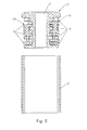
Figure 8 is a longitudinal sectional view through the hinge cap according to the previous figures, and the hollow bar in which said hinge cap may be tightly clamped; -
Figure 9 is a longitudinal sectional view of the hollow bar and the hinge cap according toFigure 8 , wherein the hinge cap is inserted in a clamped manner in the hollow bar; and -
Figures 10 through 14 illustrate another embodiment of the hinge arm with which the hinge cap may cooperate, wherein said hinge arm is adjustable to be able to adjust the distance between the gate and the pole on to which the gate is mounted. - The invention generally relates to a gate with a hollow bar, which has an open end at the top and at the bottom, and to hinge caps which are provided to be fitted in said open ends.
-
Figure 1 shows an exploded view of such a gate, provided with commercially available hinge caps. Thisgate 1 consists of arectangular frame 2, provided with awire mesh 3. Therectangular frame 2 comprises thehollow bar 3, which has an open end 4 at the top and at the bottom. Thehollow bar 3 is formed by a substantially rectangular metal tube which mostly has a square shape. In practice, this tube has a standard outside dimension of 30, 40 or 50 mm. The thickness of the tube is usually about 1.5 or 2.0 mm. Such tubes are produced by cold bending a metal sheet and longitudinally welded their free ends together. The formed weld seam is not shown in the figures but is located approximately in the middle of one of the sides of the tube. On the outside, the weld plane is flattened but on the inside of the tube, the weld seam remains. - The
hinge cap 5, which is already known and which is inserted in a clamped manner in the upper and lower open end 4 of thehollow bar 3, is entirely manufactured of a plastics material, in particular by injection moulding. It consists of acentral tube structure 6 with laterally projectingplastics ribs 7 and having at the top acover plate 8 which rests on the wall of thehollow bar 3. The centraltubular structure 6 forms anopening 9 in which oneend 10 of ahinge arm 11 is rotationally received. Thisend 10 of thehinge arm 11 thus forms the axis of the hinge. Theother end 12 is located substantially perpendicular to this rotation axis and is provided with screw-thread, to be fixed by means of thenuts 13 to a support, more particularly arigid pole 14. - In
Figure 2 is displayed the same gate, provided with the same hinge system. In this figure, the same elements as in the known gate are referred to with the same reference numerals. The only difference is that in the hinges of this gate, ahinge cap 15 according to the invention is used. - As can be seen more clearly in
Figure 8 , saidhinge cap 15 also comprises acentral tube structure 6 and laterally projectingplastics ribs 7. The centraltubular structure 6 is provided at the top with acover plate 8 which rests on the wall of the hollow bar 3 (or on which the wall of thehollow bar 3 rests for the bottom hinge). At the bottom, thecentral tube structure 6 is provided with acollar 16 which fits with some clearance into thehollow bar 3. Thecentral tube structure 6 further forms acentral opening 9 in which the end 10 (rotation axis) of thehinge arm 11 is rotationally received, and which extends in the longitudinal direction of thebar 3. - It is essential for the hinge caps 15 according to the invention that they contain, in addition to the
plastics ribs 7, asupport skeleton 17. Thissupport skeleton 17 is displayed in the centre image ofFigure 5 , and forms thecentral tube structure 6, in which theopening 9 for thehinge pin 11 is formed. In the preferred embodiment shown in the figures, as can be clearly seen inFigure 5 , theplastics ribs 7 are formed byplastics elements 18 which may be clipped laterally on thetube structure 6. According to the invention, thesupport skeleton 17 showslateral projections 19 which extend in unloaded condition of thehinge Figure 9 ). When the hinge is loaded, theplastics ribs 7 experience a deformation in which the lateral projections 19 (more specifically, at least some of them) starting from a certain load, provide an additional support of thehinge cap 15 against the inside of thehollow bar 3. In order to be able to absorb higher loads, thesupport skeleton 17 is made of a material which has a higher hardness than the plastics material of which theribs 7 are made. The distance over which thelateral projections 19 extend, in the unloaded condition of the hinge, from the inside of thehollow bar 3, is preferably less than 2.0 mm, more preferably less than 1.5 mm and most preferably less than or equal to 1.0 mm. - The
plastics ribs 7 ensure that thehinge cap 15 is clamped in thehollow bar 3. As can be seen inFigure 9 , theseplastics ribs 7 are hereby slightly deformed against the inside of thehollow bar 3. However, the harderlateral projections 19 of thesupport skeleton 17 remain, when the hinge is not loaded, at a short distance from the inside of thehollow bar 3, such that these may provide for an additional support, but do not hamper the smooth insertion of thehinge cap 15 in thehollow bar 3. - In the preferred embodiment, shown in the figures, the
lateral projections 19 of thesupport skeleton 17 are provided to extend, when theplastics ribs 7 are deformed as a result of a load on thehinge hollow bar 3. In a variant embodiment, the plastics material of which theribs 7 are made, could form a relatively thin buffer between the ends of thelateral projections 19 in the inside of thehollow bar 3, such that theseprojections 19 do not directly come into contact with the inside of thehollow bar 3, but are still able to offer additional support. Preferably, said plastics buffer has a limited thickness which, in particular, is less than 5 mm, and most preferably less than 3 mm. - The plastics material the
ribs 7 are made of, preferably contains polyethylene (PE) or polyoxymethylene (POM). To reduce the hardness of such plastics, it is known to add plasticisers thereto. The plastics material of theribs 7 preferably has a Shore D hardness, measured according to ASTM D2240, which is less than 80, preferably less than 70, and more preferably less than 60. However, this Shore D hardness is preferably higher than 10, more preferably higher than 20, and most preferably higher than 30. - The
support skeleton 17 may also be made of a plastics material, in particular of a plastics material which is harder than the plastics material of theribs 7. Thesupport skeleton 17 may be made, for example, of glass-fibre reinforced polyamide (PA) or, alternatively, also of acrylonitrile-butadiene-styrene (ABS). However, thesupport skeleton 17 is preferably made of a metal material, for example of aluminium or of an alloy containing at least zinc and aluminium, such as Zamac, with preference being given to aluminium. Indeed, aluminium can be moulded easily and provides the necessary hardness, wherein moulding of the support skeleton is preferred since that is the simplest/cheapest way of manufacturing. - Both the part of the
hinge cap 15 with theplastics ribs 7, as well as thesupport skeleton 17 are preferably separately produced, preferably by moulding or injection moulding. So-called "over-moulding" techniques, in which thesupport skeleton 17 is provided in advance as an insert in the mould in which the plastics part is to be manufactured, are also possible but are more complex and more expensive. As described above and is clearly shown inFigure 5 , it is preferred for theplastics ribs 7 to be manufactured as part of theplastics elements 18, in which theseplastics elements 18 are preferably formed such that they can easily be clipped on thesupport skeleton 17. - The
lateral projections 19 of thesupport skeleton 17 extend preferably in at least three, more preferably in at least four layers. In thehinge cap 15 shown in the figures, there are four layers ofprojections 19, wherein the upper layer ofprojections 19 is fixed to the bottom of thecover plate 8 and wherein the bottom layer ofprojections 19 is formed by thecollar 16. Between these layers ofprojections 19, theplastics ribs 7 are positioned. - The
lateral projections 19 of thesupport skeleton 17 are preferably directed to the corners of thehollow bar 3. At these locations, thehollow bar 3 offers the highest resistance to deformation. Moreover, there are no weld seams in the corners which would hamper insertion of thehinge cap 15 by contact with thehard lateral projections 19 of thesupport skeleton 17. - From the above description of the gate and the hinge cap according to the invention, it will be understood that the invention is by no means limited to the embodiments described herein, but that all kinds of modifications may be made thereof without departing from the scope of the invention as defined by the appended claims.
- For example, the hinge arm can have a more complex shape and may possibly also be adjustable, such as the
hinge arm 500 shown inFigures 10 to 14 . Thehinge arm 500 shown in these figures, includes ahousing 510 in which the hingedend 520 of the hinge arm is mounted. Thehousing 510 itself is fixed by means of abolt 530 and anut 535 against thepole 14. - Within the
housing 510 there is atoothed rack 540 on which the hingedend 520 is arranged. As shown, the position of the hingedend 520 on thetoothed rack 540 can be adjusted according toarrow 550. Once in the correct position, the hingedend 520 can be fixed by means of abolt 525. Thebolt 525 is screwed into theend 520 and clamps aplate 560 against thetoothed rack 540. Such adjustable hinge arm enables thus to control the position of the gate.
Claims (15)
- A gate (1) with a hollow bar (3), which has an open end (4) at its top and bottom, and with two hinges attached to said bar (3), which hinges each comprise a hinge arm (11, 500) and a hinge cap (15), wherein the hinge caps (15) are at least partially made of a plastics material and are provided with laterally projecting ribs (7), made from said plastics material, with which they are clamped in the upper and in the lower open end (4) of the bar (3) of the gate, such that the plastics ribs (7) are deformed against the inside of the hollow bar (3), and wherein the hinge caps (15) exhibit an opening (9) in which one end (10, 520) of the hinge arms (11, 500) is rotationally received,
characterized in that
the hinge caps (15), in addition to said plastics ribs (7), comprise a support skeleton (17) in which said opening (9) is formed, which support skeleton (17) exhibits lateral projections (19) extending, in the unloaded state of the hinge, up to a short distance from the inside of the hollow bar (3), and which are provided, when the plastics ribs (7) are deformed as a result of a load on the hinge, to provide an additional support of the hinge cap (15) against the inside of said bar (3), wherein the support skeleton (17) is made of a material which has a higher hardness than the plastics material from which said ribs (7) are made. - A gate according to claim 1, characterized in that the support skeleton (17) is made of metal.
- A gate according to claim 2, characterized in that the support skeleton (17) is made of aluminium or of an alloy containing at least aluminium and zinc, wherein the support skeleton is preferably made of aluminium.
- A gate according to claim 1, characterized in that the support skeleton (17) is made of a plastics material, preferably of polyamide that is in particular glass-fibre-reinforced.
- A gate according to any one of the claims 1 to 4, characterized in that the support skeleton (17) is moulded.
- A gate according to any one of claims 1 to 5, characterized in that said lateral projections (19) are provided to extend, when the plastics ribs (7) are loaded as a result of a load on the hinge, up to the inside of the hollow bar (3).
- A gate according to any one of claims 1 to 6, characterized in that said plastics material contains polyethylene or polyoxymethylene.
- A gate according to any one of the claims 1 to 7, characterized in that said plastics material has a Shore D hardness, measured according to ASTM D2240, which is less than 80, preferably less than 70, and more preferably less than 60.
- A gate according to any one of the claims 1 to 8, characterized in that said plastics material has a Shore D hardness, measured according to ASTM D2240, which is higher than 10, preferably higher than 20, and more preferably higher than 30.
- A gate according to any one of the claims 1 to 9, characterized in that said hollow bar (3) has a cross-section which has a substantially rectangular shape, in particular a substantially square shape, wherein said support skeleton (17) has at least four of said lateral projections (19), each of which is directed to one of the four corners of the hollow bar (3).
- A gate according to any one of the claims 1 to 10, characterized in that the support skeleton (17) has a central tube structure (6), which forms said opening (9), wherein said plastics ribs (7) are formed by plastics elements (18), in particular by two plastics elements (18), which are laterally clamped over said tube structure (6).
- A gate according to any one of claims 1 to 11, characterized in that said lateral projections (19) extend in at least three, preferably in at least four layers, wherein between each two successive layers of projections (19) each time at least one of said plastics ribs (7) is provided.
- A gate according to any one of the claims 1 to 12, characterized in that the hinge cap (15) has a cover plate (8), which extends beyond the inside of the hollow bar (3), and which covers the hollow bar (3).
- A gate according to any one of the claims 1 to 13, characterized in that said short distance is less than 2.0 mm, preferably less than 1.5 mm, and more preferably less than or equal to 1.0 mm.
- A hinge cap for a gate (1) according to any one of the claims 1 to 13, which hinge cap (15) is at least partially made of a plastics material and is provided with laterally projecting ribs (7), made of said plastics material, intended to clamp the hinge cap (15) in an upper or lower open end (4) of a hollow bar (3) of the gate (1) by deformation of said plastics ribs (7), wherein the hinge cap (15) further comprises an opening (9) which extends in the longitudinal direction of the hinge cap (15) and which is intended to rotationally receive one end (10, 520) of a hinge arm (11, 500) which is provided to form a hinge together with the hinge cap (15), characterized in that
the hinge cap (15) adjacent to said plastics ribs (7) contains a support skeleton (17) in which said opening (9) is formed, which support skeleton (17) exhibits lateral projections (19) extending, when the hinge cap (15) is clamped by the plastics ribs (7) in said hollow bar (3), up to a short distance from the inside of said hollow bar (15), and which are provided, when the plastics ribs (7) are deformed as a result of a load on the hinge, to provide an additional support of the hinge cap (5) against the inside of said bar (3), wherein the support skeleton (17) is made of a material which has a higher hardness than the plastics material from which said ribs (7) are made.
Priority Applications (1)
| Application Number | Priority Date | Filing Date | Title |
|---|---|---|---|
| PL12199098T PL2607587T3 (en) | 2011-12-23 | 2012-12-21 | Gate and associated hinge cover |
Applications Claiming Priority (1)
| Application Number | Priority Date | Filing Date | Title |
|---|---|---|---|
| BE2011/0734A BE1020360A3 (en) | 2011-12-23 | 2011-12-23 | PORT AND HINGED CAP FOR THAT. |
Publications (2)
| Publication Number | Publication Date |
|---|---|
| EP2607587A1 true EP2607587A1 (en) | 2013-06-26 |
| EP2607587B1 EP2607587B1 (en) | 2018-02-28 |
Family
ID=47358423
Family Applications (1)
| Application Number | Title | Priority Date | Filing Date |
|---|---|---|---|
| EP12199098.0A Active EP2607587B1 (en) | 2011-12-23 | 2012-12-21 | Gate and associated hinge cap |
Country Status (4)
| Country | Link |
|---|---|
| EP (1) | EP2607587B1 (en) |
| BE (1) | BE1020360A3 (en) |
| ES (1) | ES2668824T3 (en) |
| PL (1) | PL2607587T3 (en) |
Citations (1)
| Publication number | Priority date | Publication date | Assignee | Title |
|---|---|---|---|---|
| GB2430967A (en) * | 2005-10-08 | 2007-04-11 | Red Lan | Safety gate with pair of restoring mechanisms |
-
2011
- 2011-12-23 BE BE2011/0734A patent/BE1020360A3/en active
-
2012
- 2012-12-21 PL PL12199098T patent/PL2607587T3/en unknown
- 2012-12-21 ES ES12199098.0T patent/ES2668824T3/en active Active
- 2012-12-21 EP EP12199098.0A patent/EP2607587B1/en active Active
Patent Citations (1)
| Publication number | Priority date | Publication date | Assignee | Title |
|---|---|---|---|---|
| GB2430967A (en) * | 2005-10-08 | 2007-04-11 | Red Lan | Safety gate with pair of restoring mechanisms |
Also Published As
| Publication number | Publication date |
|---|---|
| ES2668824T3 (en) | 2018-05-22 |
| PL2607587T3 (en) | 2018-08-31 |
| EP2607587B1 (en) | 2018-02-28 |
| BE1020360A3 (en) | 2013-08-06 |
Similar Documents
| Publication | Publication Date | Title |
|---|---|---|
| EP3675221B1 (en) | Battery box | |
| JP4933476B2 (en) | Ball joint | |
| US20180338623A1 (en) | Portable chair and cup holder assembly | |
| US20120139323A1 (en) | Backrest Device For A Chair | |
| US20080078904A1 (en) | Grab bar mount system | |
| JP2012519031A5 (en) | Spinal rod | |
| EP2607587B1 (en) | Gate and associated hinge cap | |
| BR112019019708B1 (en) | MOUNTING PLATE ARRANGEMENT AND CORRESPONDING METHOD | |
| US6591978B2 (en) | Conveyor bracket | |
| US20130092074A1 (en) | Safety flag for a watercraft | |
| US20100044612A1 (en) | Tapping valve with a plastic valve housing for shipping and storage tanks for liquids | |
| EP2505468B1 (en) | Windshield device for saddle-ride type vehicles | |
| EP3073024A1 (en) | Arm for awnings | |
| JP5214545B2 (en) | Mirror cabinet door mounting structure | |
| JP5481865B2 (en) | Hinge cap | |
| US20150308137A1 (en) | Flow Diverting Weir for a Swimming Pool Skimmer | |
| US6769284B1 (en) | Hinge adjusting tool | |
| CN101206926A (en) | Panel tv wall hanging device capable of adjusting angle | |
| CN210101899U (en) | A kind of inner wall T-shaped structure pipe material | |
| JP5006219B2 (en) | Waterproof cap, wiper pivot, and vehicle wiper device | |
| AU2010100367A4 (en) | Slimline Water Tank | |
| CN222242298U (en) | Paint bucket press | |
| EP1837220A3 (en) | Reinforced vehicle door | |
| CN220482561U (en) | Pipe fitting bending clamp | |
| JP4231006B2 (en) | Hinge structure of refrigerator |
Legal Events
| Date | Code | Title | Description |
|---|---|---|---|
| AK | Designated contracting states |
Kind code of ref document: A1 Designated state(s): AL AT BE BG CH CY CZ DE DK EE ES FI FR GB GR HR HU IE IS IT LI LT LU LV MC MK MT NL NO PL PT RO RS SE SI SK SM TR |
|
| AX | Request for extension of the european patent |
Extension state: BA ME |
|
| PUAI | Public reference made under article 153(3) epc to a published international application that has entered the european phase |
Free format text: ORIGINAL CODE: 0009012 |
|
| 17P | Request for examination filed |
Effective date: 20130927 |
|
| RBV | Designated contracting states (corrected) |
Designated state(s): AL AT BE BG CH CY CZ DE DK EE ES FI FR GB GR HR HU IE IS IT LI LT LU LV MC MK MT NL NO PL PT RO RS SE SI SK SM TR |
|
| GRAP | Despatch of communication of intention to grant a patent |
Free format text: ORIGINAL CODE: EPIDOSNIGR1 |
|
| RIC1 | Information provided on ipc code assigned before grant |
Ipc: E05D 7/08 20060101ALI20150216BHEP Ipc: E05D 5/16 20060101ALI20150216BHEP Ipc: E05D 5/14 20060101AFI20150216BHEP Ipc: E05D 5/02 20060101ALI20150216BHEP |
|
| INTG | Intention to grant announced |
Effective date: 20150323 |
|
| 17Q | First examination report despatched |
Effective date: 20150720 |
|
| INTC | Intention to grant announced (deleted) | ||
| GRAP | Despatch of communication of intention to grant a patent |
Free format text: ORIGINAL CODE: EPIDOSNIGR1 |
|
| INTG | Intention to grant announced |
Effective date: 20171006 |
|
| GRAS | Grant fee paid |
Free format text: ORIGINAL CODE: EPIDOSNIGR3 |
|
| GRAA | (expected) grant |
Free format text: ORIGINAL CODE: 0009210 |
|
| AK | Designated contracting states |
Kind code of ref document: B1 Designated state(s): AL AT BE BG CH CY CZ DE DK EE ES FI FR GB GR HR HU IE IS IT LI LT LU LV MC MK MT NL NO PL PT RO RS SE SI SK SM TR |
|
| REG | Reference to a national code |
Ref country code: GB Ref legal event code: FG4D Ref country code: CH Ref legal event code: EP |
|
| REG | Reference to a national code |
Ref country code: AT Ref legal event code: REF Ref document number: 974330 Country of ref document: AT Kind code of ref document: T Effective date: 20180315 |
|
| REG | Reference to a national code |
Ref country code: IE Ref legal event code: FG4D |
|
| REG | Reference to a national code |
Ref country code: DE Ref legal event code: R096 Ref document number: 602012043316 Country of ref document: DE |
|
| REG | Reference to a national code |
Ref country code: ES Ref legal event code: FG2A Ref document number: 2668824 Country of ref document: ES Kind code of ref document: T3 Effective date: 20180522 |
|
| REG | Reference to a national code |
Ref country code: NL Ref legal event code: FP |
|
| REG | Reference to a national code |
Ref country code: LT Ref legal event code: MG4D |
|
| REG | Reference to a national code |
Ref country code: AT Ref legal event code: MK05 Ref document number: 974330 Country of ref document: AT Kind code of ref document: T Effective date: 20180228 |
|
| PG25 | Lapsed in a contracting state [announced via postgrant information from national office to epo] |
Ref country code: FI Free format text: LAPSE BECAUSE OF FAILURE TO SUBMIT A TRANSLATION OF THE DESCRIPTION OR TO PAY THE FEE WITHIN THE PRESCRIBED TIME-LIMIT Effective date: 20180228 Ref country code: HR Free format text: LAPSE BECAUSE OF FAILURE TO SUBMIT A TRANSLATION OF THE DESCRIPTION OR TO PAY THE FEE WITHIN THE PRESCRIBED TIME-LIMIT Effective date: 20180228 Ref country code: NO Free format text: LAPSE BECAUSE OF FAILURE TO SUBMIT A TRANSLATION OF THE DESCRIPTION OR TO PAY THE FEE WITHIN THE PRESCRIBED TIME-LIMIT Effective date: 20180528 Ref country code: CY Free format text: LAPSE BECAUSE OF FAILURE TO SUBMIT A TRANSLATION OF THE DESCRIPTION OR TO PAY THE FEE WITHIN THE PRESCRIBED TIME-LIMIT Effective date: 20180228 Ref country code: LT Free format text: LAPSE BECAUSE OF FAILURE TO SUBMIT A TRANSLATION OF THE DESCRIPTION OR TO PAY THE FEE WITHIN THE PRESCRIBED TIME-LIMIT Effective date: 20180228 |
|
| PG25 | Lapsed in a contracting state [announced via postgrant information from national office to epo] |
Ref country code: BG Free format text: LAPSE BECAUSE OF FAILURE TO SUBMIT A TRANSLATION OF THE DESCRIPTION OR TO PAY THE FEE WITHIN THE PRESCRIBED TIME-LIMIT Effective date: 20180528 Ref country code: RS Free format text: LAPSE BECAUSE OF FAILURE TO SUBMIT A TRANSLATION OF THE DESCRIPTION OR TO PAY THE FEE WITHIN THE PRESCRIBED TIME-LIMIT Effective date: 20180228 Ref country code: AT Free format text: LAPSE BECAUSE OF FAILURE TO SUBMIT A TRANSLATION OF THE DESCRIPTION OR TO PAY THE FEE WITHIN THE PRESCRIBED TIME-LIMIT Effective date: 20180228 Ref country code: SE Free format text: LAPSE BECAUSE OF FAILURE TO SUBMIT A TRANSLATION OF THE DESCRIPTION OR TO PAY THE FEE WITHIN THE PRESCRIBED TIME-LIMIT Effective date: 20180228 Ref country code: LV Free format text: LAPSE BECAUSE OF FAILURE TO SUBMIT A TRANSLATION OF THE DESCRIPTION OR TO PAY THE FEE WITHIN THE PRESCRIBED TIME-LIMIT Effective date: 20180228 Ref country code: GR Free format text: LAPSE BECAUSE OF FAILURE TO SUBMIT A TRANSLATION OF THE DESCRIPTION OR TO PAY THE FEE WITHIN THE PRESCRIBED TIME-LIMIT Effective date: 20180529 |
|
| PG25 | Lapsed in a contracting state [announced via postgrant information from national office to epo] |
Ref country code: EE Free format text: LAPSE BECAUSE OF FAILURE TO SUBMIT A TRANSLATION OF THE DESCRIPTION OR TO PAY THE FEE WITHIN THE PRESCRIBED TIME-LIMIT Effective date: 20180228 Ref country code: RO Free format text: LAPSE BECAUSE OF FAILURE TO SUBMIT A TRANSLATION OF THE DESCRIPTION OR TO PAY THE FEE WITHIN THE PRESCRIBED TIME-LIMIT Effective date: 20180228 Ref country code: AL Free format text: LAPSE BECAUSE OF FAILURE TO SUBMIT A TRANSLATION OF THE DESCRIPTION OR TO PAY THE FEE WITHIN THE PRESCRIBED TIME-LIMIT Effective date: 20180228 |
|
| REG | Reference to a national code |
Ref country code: DE Ref legal event code: R097 Ref document number: 602012043316 Country of ref document: DE |
|
| PG25 | Lapsed in a contracting state [announced via postgrant information from national office to epo] |
Ref country code: DK Free format text: LAPSE BECAUSE OF FAILURE TO SUBMIT A TRANSLATION OF THE DESCRIPTION OR TO PAY THE FEE WITHIN THE PRESCRIBED TIME-LIMIT Effective date: 20180228 Ref country code: SK Free format text: LAPSE BECAUSE OF FAILURE TO SUBMIT A TRANSLATION OF THE DESCRIPTION OR TO PAY THE FEE WITHIN THE PRESCRIBED TIME-LIMIT Effective date: 20180228 Ref country code: SM Free format text: LAPSE BECAUSE OF FAILURE TO SUBMIT A TRANSLATION OF THE DESCRIPTION OR TO PAY THE FEE WITHIN THE PRESCRIBED TIME-LIMIT Effective date: 20180228 Ref country code: CZ Free format text: LAPSE BECAUSE OF FAILURE TO SUBMIT A TRANSLATION OF THE DESCRIPTION OR TO PAY THE FEE WITHIN THE PRESCRIBED TIME-LIMIT Effective date: 20180228 |
|
| PLBE | No opposition filed within time limit |
Free format text: ORIGINAL CODE: 0009261 |
|
| STAA | Information on the status of an ep patent application or granted ep patent |
Free format text: STATUS: NO OPPOSITION FILED WITHIN TIME LIMIT |
|
| REG | Reference to a national code |
Ref country code: BE Ref legal event code: PD Owner name: LOCINOX; BE Free format text: DETAILS ASSIGNMENT: CHANGE OF OWNER(S), CESSION; FORMER OWNER NAME: TALPE, JOSEPH Effective date: 20181210 |
|
| 26N | No opposition filed |
Effective date: 20181129 |
|
| PG25 | Lapsed in a contracting state [announced via postgrant information from national office to epo] |
Ref country code: SI Free format text: LAPSE BECAUSE OF FAILURE TO SUBMIT A TRANSLATION OF THE DESCRIPTION OR TO PAY THE FEE WITHIN THE PRESCRIBED TIME-LIMIT Effective date: 20180228 |
|
| REG | Reference to a national code |
Ref country code: CH Ref legal event code: PL |
|
| PG25 | Lapsed in a contracting state [announced via postgrant information from national office to epo] |
Ref country code: LU Free format text: LAPSE BECAUSE OF NON-PAYMENT OF DUE FEES Effective date: 20181221 Ref country code: MC Free format text: LAPSE BECAUSE OF FAILURE TO SUBMIT A TRANSLATION OF THE DESCRIPTION OR TO PAY THE FEE WITHIN THE PRESCRIBED TIME-LIMIT Effective date: 20180228 |
|
| REG | Reference to a national code |
Ref country code: IE Ref legal event code: MM4A |
|
| PG25 | Lapsed in a contracting state [announced via postgrant information from national office to epo] |
Ref country code: IE Free format text: LAPSE BECAUSE OF NON-PAYMENT OF DUE FEES Effective date: 20181221 |
|
| PG25 | Lapsed in a contracting state [announced via postgrant information from national office to epo] |
Ref country code: CH Free format text: LAPSE BECAUSE OF NON-PAYMENT OF DUE FEES Effective date: 20181231 Ref country code: LI Free format text: LAPSE BECAUSE OF NON-PAYMENT OF DUE FEES Effective date: 20181231 |
|
| PG25 | Lapsed in a contracting state [announced via postgrant information from national office to epo] |
Ref country code: MT Free format text: LAPSE BECAUSE OF NON-PAYMENT OF DUE FEES Effective date: 20181221 |
|
| PG25 | Lapsed in a contracting state [announced via postgrant information from national office to epo] |
Ref country code: TR Free format text: LAPSE BECAUSE OF FAILURE TO SUBMIT A TRANSLATION OF THE DESCRIPTION OR TO PAY THE FEE WITHIN THE PRESCRIBED TIME-LIMIT Effective date: 20180228 |
|
| PG25 | Lapsed in a contracting state [announced via postgrant information from national office to epo] |
Ref country code: PT Free format text: LAPSE BECAUSE OF FAILURE TO SUBMIT A TRANSLATION OF THE DESCRIPTION OR TO PAY THE FEE WITHIN THE PRESCRIBED TIME-LIMIT Effective date: 20180228 |
|
| PG25 | Lapsed in a contracting state [announced via postgrant information from national office to epo] |
Ref country code: MK Free format text: LAPSE BECAUSE OF NON-PAYMENT OF DUE FEES Effective date: 20180228 Ref country code: HU Free format text: LAPSE BECAUSE OF FAILURE TO SUBMIT A TRANSLATION OF THE DESCRIPTION OR TO PAY THE FEE WITHIN THE PRESCRIBED TIME-LIMIT; INVALID AB INITIO Effective date: 20121221 |
|
| PG25 | Lapsed in a contracting state [announced via postgrant information from national office to epo] |
Ref country code: IS Free format text: LAPSE BECAUSE OF FAILURE TO SUBMIT A TRANSLATION OF THE DESCRIPTION OR TO PAY THE FEE WITHIN THE PRESCRIBED TIME-LIMIT Effective date: 20180628 |
|
| PGFP | Annual fee paid to national office [announced via postgrant information from national office to epo] |
Ref country code: NL Payment date: 20251119 Year of fee payment: 14 |
|
| PGFP | Annual fee paid to national office [announced via postgrant information from national office to epo] |
Ref country code: GB Payment date: 20251223 Year of fee payment: 14 |
|
| PGFP | Annual fee paid to national office [announced via postgrant information from national office to epo] |
Ref country code: IT Payment date: 20251218 Year of fee payment: 14 |
|
| PGFP | Annual fee paid to national office [announced via postgrant information from national office to epo] |
Ref country code: FR Payment date: 20251119 Year of fee payment: 14 |
|
| PGFP | Annual fee paid to national office [announced via postgrant information from national office to epo] |
Ref country code: BE Payment date: 20251119 Year of fee payment: 14 |
|
| PGFP | Annual fee paid to national office [announced via postgrant information from national office to epo] |
Ref country code: PL Payment date: 20251127 Year of fee payment: 14 |
|
| PGFP | Annual fee paid to national office [announced via postgrant information from national office to epo] |
Ref country code: ES Payment date: 20260122 Year of fee payment: 14 |
|
| PGFP | Annual fee paid to national office [announced via postgrant information from national office to epo] |
Ref country code: DE Payment date: 20251229 Year of fee payment: 14 |