EP2607570A1 - Articulation device for a foldable awning arm - Google Patents
Articulation device for a foldable awning arm Download PDFInfo
- Publication number
- EP2607570A1 EP2607570A1 EP11380104.7A EP11380104A EP2607570A1 EP 2607570 A1 EP2607570 A1 EP 2607570A1 EP 11380104 A EP11380104 A EP 11380104A EP 2607570 A1 EP2607570 A1 EP 2607570A1
- Authority
- EP
- European Patent Office
- Prior art keywords
- articulation
- core
- retention
- articulation device
- housing
- Prior art date
- Legal status (The legal status is an assumption and is not a legal conclusion. Google has not performed a legal analysis and makes no representation as to the accuracy of the status listed.)
- Pending
Links
Images



Classifications
-
- E—FIXED CONSTRUCTIONS
- E04—BUILDING
- E04F—FINISHING WORK ON BUILDINGS, e.g. STAIRS, FLOORS
- E04F10/00—Sunshades, e.g. Florentine blinds or jalousies; Outside screens; Awnings or baldachins
- E04F10/02—Sunshades, e.g. Florentine blinds or jalousies; Outside screens; Awnings or baldachins of flexible canopy materials, e.g. canvas ; Baldachins
- E04F10/06—Sunshades, e.g. Florentine blinds or jalousies; Outside screens; Awnings or baldachins of flexible canopy materials, e.g. canvas ; Baldachins comprising a roller-blind with means for holding the end away from a building
- E04F10/0611—Sunshades, e.g. Florentine blinds or jalousies; Outside screens; Awnings or baldachins of flexible canopy materials, e.g. canvas ; Baldachins comprising a roller-blind with means for holding the end away from a building with articulated arms supporting the movable end of the blind for deployment of the blind
-
- E—FIXED CONSTRUCTIONS
- E04—BUILDING
- E04F—FINISHING WORK ON BUILDINGS, e.g. STAIRS, FLOORS
- E04F10/00—Sunshades, e.g. Florentine blinds or jalousies; Outside screens; Awnings or baldachins
- E04F10/02—Sunshades, e.g. Florentine blinds or jalousies; Outside screens; Awnings or baldachins of flexible canopy materials, e.g. canvas ; Baldachins
- E04F10/06—Sunshades, e.g. Florentine blinds or jalousies; Outside screens; Awnings or baldachins of flexible canopy materials, e.g. canvas ; Baldachins comprising a roller-blind with means for holding the end away from a building
- E04F10/0611—Sunshades, e.g. Florentine blinds or jalousies; Outside screens; Awnings or baldachins of flexible canopy materials, e.g. canvas ; Baldachins comprising a roller-blind with means for holding the end away from a building with articulated arms supporting the movable end of the blind for deployment of the blind
- E04F10/0618—Sunshades, e.g. Florentine blinds or jalousies; Outside screens; Awnings or baldachins of flexible canopy materials, e.g. canvas ; Baldachins comprising a roller-blind with means for holding the end away from a building with articulated arms supporting the movable end of the blind for deployment of the blind whereby the pivot axis of the articulation is perpendicular to the roller
-
- E—FIXED CONSTRUCTIONS
- E04—BUILDING
- E04F—FINISHING WORK ON BUILDINGS, e.g. STAIRS, FLOORS
- E04F10/00—Sunshades, e.g. Florentine blinds or jalousies; Outside screens; Awnings or baldachins
- E04F10/02—Sunshades, e.g. Florentine blinds or jalousies; Outside screens; Awnings or baldachins of flexible canopy materials, e.g. canvas ; Baldachins
- E04F10/06—Sunshades, e.g. Florentine blinds or jalousies; Outside screens; Awnings or baldachins of flexible canopy materials, e.g. canvas ; Baldachins comprising a roller-blind with means for holding the end away from a building
- E04F10/0644—Sunshades, e.g. Florentine blinds or jalousies; Outside screens; Awnings or baldachins of flexible canopy materials, e.g. canvas ; Baldachins comprising a roller-blind with means for holding the end away from a building with mechanisms for unrolling or balancing the blind
- E04F10/0651—Sunshades, e.g. Florentine blinds or jalousies; Outside screens; Awnings or baldachins of flexible canopy materials, e.g. canvas ; Baldachins comprising a roller-blind with means for holding the end away from a building with mechanisms for unrolling or balancing the blind acting on the arms
Definitions
- the present invention generally relates to an articulation device for a retractable awning arm, and more particularly to an articulation device including bearings for connecting two segments of a retractable awning arm to one another in an articulated manner.
- WO 2008037815 A1 discloses an articulation device for a retractable awning arm comprising a first articulation member fixed to a first arm segment and a second articulation member fixed to a second arm segment.
- the first articulation member has formed two fork branches between which there is supported a core configured around an articulation axis.
- the core has an anchor in which there is attached a thickened terminal of a flexible tie element connected to an elastic member housed inside said second arm segment and a supporting surface on which said flexible tie element is supported.
- the second articulation member has a surrounding wall arranged around the core such that there is clearance sufficient for accommodating the flexible tie element between both.
- each bearing comprises an inner annular element fixed to the core and an outer annular element fixed to the surrounding wall.
- the parts forming the articulation device are kept in position by retention parts having respective portions inserted such that they cannot rotate through respective openings formed in the fork branches and coupled such that they cannot rotate in respective housings formed in the core, and by a central tubular rod inserted through the corresponding holes formed in the core and in the retention parts, where the ends of said central rod are flared with respect to the mouths of the holes of the retention parts.
- the present invention aims to solve the foregoing and other problems by providing an articulation device for a retractable awning arm, which comprises a first articulation member fixed to a first arm segment and a second articulation member fixed to a second arm segment.
- the first articulation member has two fork branches between which a core configured around an articulation axis is supported.
- This core has an anchor in which there is attached a thickened terminal of a flexible tie element connected to an elastic member housed inside said second arm segment and a supporting surface, generally eccentric with respect to the articulation axis, on which said flexible tie element is supported.
- the second articulation member has a surrounding wall arranged around the core leaving a clearance between both sufficient for accommodating the flexible tie element.
- the relative rotational movements of the first and second articulation members around the articulation axis are guided by bearing means.
- the core is connected to the fork branches by first and second retention parts inserted such that they can neither rotate nor go through respective openings formed in the fork branches and coupled such that they cannot rotate in respective housings formed in the core, and by connecting means keeping said first and second retention parts connected to one another.
- These connecting means comprise a connecting screw inserted through a through hole formed in the first retention part and screwed in a threaded hole formed in the second retention part or in a nut retained such that it can neither rotate nor move axially in a housing of the second retention part.
- the option of screwing the retention screw directly in a threaded hole formed in the second retention part is acceptable if the material of the second retention part is hard enough, such as steel, for example. Nevertheless, when the material of the second retention part is relatively soft, such as aluminium alloy or plastic for example, the option of screwing the retention screw in a nut retained in a housing of the second retention part will be preferred.
- the two retention parts keeping the core connected to the fork branches of the first articulation member are connected to one another by the mentioned connecting screw, which can be loosened and removed with ease, which allows disassembling the articulation device without the need of destroying any component, and reassembling it without the need of special tools.
- said through hole of the first retention part is parallel to the articulation axis, and more preferably is aligned with the articulation axis.
- the second retention part comprises an axial cavity sized for receiving an end portion of the rod of said connecting screw, and the housing is in the form of a groove transverse to said axial cavity and perpendicular to the articulation axis.
- the housing has a radial access opening at a lateral side of the second retention part, and the axial cavity has a longitudinal opening at the same lateral side of the second retention part and intersects said radial access opening of the housing.
- the first and second retention parts have respective pyramidal portions which in position of use are facing one another, and said housings of the core are formed at opposite axial ends thereof and configured for fitting said pyramidal portions.
- the through hole which is preferably aligned with the articulation axis, and the axial cavity are positioned at the centre of the respective pyramidal portions of the first and second retention parts.
- each of the first and second retention parts has one or more protruding plugs fitting into respective recesses formed in the corresponding fork branch.
- each of the first and second retention parts has a cover portion configured to be placed on an area of the respective fork branch around the mentioned opening through which the pyramidal portion is inserted and the one or more plugs extend from an inner surface of said cover portion.
- the through hole of the first retention part in which the connecting screw is inserted has a countersink at an axial end adjacent to an outer side of the corresponding cover portion.
- This countersink is sized for housing the head of the connecting screw.
- the head of the connecting screw is conical shaped and has a gripping element for an Allen-type rod key, therefore the countersink is relatively discrete and in condition of use it can be covered with a conventional lid secured in said gripping element.
- the outer side of the corresponding cover portion of the second retention part is smooth as a result of the fact that the axial cavity is not a through hole and is closed at this outer side.
- the mentioned bearing means comprise a pair of bearings, each of which comprises an inner annular element fixed to the core, which is in turn fixed to the fork branches of the first articulation member, and an outer annular element fixed to the surrounding wall of the second articulation member.
- the core has a pair of inner seats configured for receiving said inner annular elements of the bearings, and both the anchor and the supporting surface are located between said pair of inner seats to facilitate the actuation of the mentioned flexible tie element, which is preferably in the form of a flat belt, and the attachment of the thickened terminal thereof.
- the surrounding wall has a pair of outer seats configured for receiving said outer annular elements of the pair of bearings.
- the inner and outer seats can be like those described in the mentioned international patent application WO 2008037815 A1 .
- each of the first and second retention parts has a plurality of said plugs distributed around the articulation axis, and the fork branches have a plurality of said recesses through which the protruding plugs are inserted, and the protruding plugs project from an inner surface of the corresponding fork branch for contacting with the inner annular element of the corresponding bearing.
- both bearings are ball or roller bearings.
- one of the bearings is a ball or roller bearing and the other is a friction bearing
- another embodiment in which both bearings are friction bearings are also within the scope of the present invention.
- at least one of them could comprise a single annular element fixed to the core and in sliding contact with the surrounding wall or vice versa.
- a retractable awning arm including a first arm segment 1 and a second arm segment 2 having adjacent ends connected to one another by an articulation device 50 according to an embodiment of the present invention.
- a first end articulation element 25 by means of which the awning arm is connected to a load bar (not shown) fixed at a front end of an awning canvas (not shown)
- a second end articulation element 26 by means of which the awning arm is connected to a support (not shown) adjacent to a winding bar (not shown) on which the awning canvas is wound.
- the first and second arm segments 1, 2 can perform relative rotations around an articulation axis E between a folded position ( Figures 1 to 4 ) and an extended position ( Figures 5 and 6 ).
- the articulation device 50 comprises a first articulation member 4 fixed to the first arm segment 1 and a second articulation member 5 fixed to the second arm segment 2.
- the first and second arm segments 1, 2 are hollow profiles made of extruded aluminium and said first and second articulation members 4, 5 have respective connecting portions 27, 28 ( Figure 2 ) inserted tightly at the adjacent ends of the respective hollow profiles.
- the first articulation member 4 has two fork branches 4a, 4b parallel to and spaced apart from one another, and the second articulation member 5 has a surrounding wall 9 in the form of a ring, the height of which is only a little less than the distance between said two fork branches 4a, 4b.
- the second articulation member 5 also has a passage 29 communicating an inner space of the surrounding wall 9 with the hollow inner space of the profile forming the second arm segment 2.
- the articulation device 50 further comprises a core 6 configured around said articulation axis E and supported between the two fork branches 4a, 4b of the first articulation member 4.
- This core 6 is fixed to the fork branches 4a, 4b by first and second retention parts 13, 14 shown separately in Figure 10 which will be described in detail below, and the surrounding wall 9 of the second articulation member 5 is arranged surrounding the core 6. Between the surrounding wall 9 and the core 6 there is a clearance sized for accommodating a flexible tie element 30 in the form of a flat belt the function of which will be described below.
- the first and second articulation members 4, 5, the core 6 and the first and second retention parts 13, 14 are preferably obtained by molding an aluminium alloy although other materials and other forming techniques are possible.
- each of these bearings 11, 12 comprises an inner annular element 11a, 12a fixed to the core 6 and an outer annular element 11b, 12b fixed to the surrounding wall 9.
- the core 6 has a pair of inner seats 23a, 23b configured for receiving the inner annular elements 11a, 12a of the respective bearings 11, 12, and the surrounding wall 9 has a pair of outer seats 24a, 24b configured for receiving the outer annular elements 11b, 12b of the respective bearings 11, 12.
- the surrounding wall 9 of the second articulation members 5 has a protruding stop 33 interfering with a recess stop 34 of the first articulation members 4 for limiting the relative rotation of the first and second articulation members 4, 5 in the extended position ( Figure 5 ).
- the core 6, which is shown individually in Figure 9 also has an anchor 7 in which there is attached a terminal 31 of the mentioned flexible tie element 30, and a supporting surface 8 on which a portion of said flexible tie element 30 is supported.
- the pair of inner seats 23a, 23b are located at opposite ends of the core 6, and the anchor 7 and the supporting surface 8 are located between the inner seats 23a, 23b.
- the flexible tie element 30 is introduced into the second arm segment 2 through the mentioned passage 29 ( Figure 2 ), and its other end (not shown) opposite the terminal 31 is connected to an elastic member, such as a helical spring (not shown), housed and secured inside the second arm segment 2.
- an elastic member such as a helical spring (not shown) housed and secured inside the second arm segment 2.
- the tension of said elastic member is transmitted to the core 6 by the flexible tie element 30 and pushes the first and second arm segments 1, 2 towards the extended position.
- Figure 10 separately shows the aforementioned first and second retention parts 13, 14, each of which comprises a relatively wide cover portion 13b, 14b and a narrower pyramidal portion 13a, 14a extending inwards from the respective cover portion 13b, 14b.
- the cover portion 13b, 14b of each first and second retention parts 13, 14 is configured to be placed on a recessed area of the respective fork branch 4a, 4b ( Figure 3 ).
- Each of the first and second retention parts 13, 14 also has a plurality of protruding plugs 22a, 22b extending from an inner surface of the corresponding cover portion 13b, 14b distributed around the articulation axis E.
- the fork branches 4a, 4b of the first articulation member 4 have formed in a central region thereof respective openings 15a, 15b through which the pyramidal portions 13a, 14a of the respective first and second retention parts 13, 14 are inserted.
- the fork branches 4a, 4b further comprise a plurality of recesses 32a, 32b in which the protruding plugs 22a, 22b are fitted.
- the protruding plugs 22a, 22b are sized such that they project from inner surfaces of the respective fork branches 4a, 4b when the first and second retention parts 13, 14 are assembled.
- the contact of the cover portions 13b, 14b with the recessed area around the openings 15a, 15b prevents the first and second retention parts 13, 14 from being able to pass through the openings 15a, 15b of the first and second fork branches 4a, 4b, and the fitting of the protruding plugs 22a, 22b into the recesses 32a, 32b prevents the first and second retention parts 13, 14 from being able to rotate with respect to the first and second fork branches 4a, 4b.
- the core 6 has a pair of housings 16a, 16b (only one of which is shown in Figure 9 ) open in the opposite axial ends thereof in which the pyramidal portions 13a, 14a of the respective first and second retention parts 13, 14 are fitted.
- the housings 16a, 16b have a shape complementary to that of the pyramidal portions 13a, 14a, thereby the core 6 cannot rotate in relation to the first and second retention parts 13, 14 and consequently, it also cannot rotate in relation to the first and second fork branches 4a, 4b of the first articulation member 4.
- the first retention part 13 ( Figures 3 and 10 ) has a through hole 18 aligned with the articulation axis E.
- This through hole 18 has an opening at an inner end of the pyramidal portion 13a and an opening with a countersink 18a at an axial end adjacent to an outer side of the first retention part 13.
- the through hole 18 is sized for receiving the rod of a connecting screw 17 and the countersink 18a is sized for housing a head 17a of the connecting screw 17 such that the head 17a does not project from the outer surface of the cover portion 13b.
- the second retention part 14 ( Figures 3 and 10 ) comprises a housing 20 and an axial cavity 21 aligned with the articulation axis E.
- the axial cavity 21 is in the form of a channel with an axial opening at the inner end of the pyramidal portion 14a and a longitudinal opening along the pyramidal portion 14a
- the housing 20 is in the form of a groove transverse to said axial cavity 21 and perpendicular to the articulation axis E with a radial access opening at the same lateral side as the longitudinal opening of the axial cavity 21. Therefore, the longitudinal opening of the axial cavity 21 intersects with the radial access opening of the housing 20 ( Figure 10 ).
- the axial cavity 21 is sized for receiving an end portion of the rod of the connecting screw 17, and the housing 20 is sized for housing a nut 19 and configured for retaining said nut 19 such that it can neither rotate nor move axially in relation to the second retention part 14.
- the articulation device comprises connecting means including the mentioned connecting screw 17 and nut 19.
- the connecting screw 17 is inserted through the through hole 18 formed in the first retention part 13 and screwed in the nut 19 retained in the housing 20 of the second retention part 14.
- the first and second retention parts 13, 14 are attracted to one another until the inner surfaces of the protruding plugs 22a, 22b press the inner annular elements 11a, 12a of the respective bearings 11, 12 against the corresponding inner seats 23a, 23b formed in the core 6.
- the first and second retention parts 13, 14 can be removed and the articulation device can be easily disassembled in a reversible manner.
Landscapes
- Engineering & Computer Science (AREA)
- Architecture (AREA)
- Civil Engineering (AREA)
- Structural Engineering (AREA)
- Pivots And Pivotal Connections (AREA)
- Rehabilitation Tools (AREA)
Abstract
Description
- The present invention generally relates to an articulation device for a retractable awning arm, and more particularly to an articulation device including bearings for connecting two segments of a retractable awning arm to one another in an articulated manner.
- International patent application
WO 2008037815 A1 discloses an articulation device for a retractable awning arm comprising a first articulation member fixed to a first arm segment and a second articulation member fixed to a second arm segment. The first articulation member has formed two fork branches between which there is supported a core configured around an articulation axis. The core has an anchor in which there is attached a thickened terminal of a flexible tie element connected to an elastic member housed inside said second arm segment and a supporting surface on which said flexible tie element is supported. The second articulation member has a surrounding wall arranged around the core such that there is clearance sufficient for accommodating the flexible tie element between both. - In the mentioned international patent application
WO 2008037815 A1 , the relative rotation between the first and second articulation members is guided by a pair of bearings coaxial with the articulation axis. Each bearing comprises an inner annular element fixed to the core and an outer annular element fixed to the surrounding wall. The parts forming the articulation device are kept in position by retention parts having respective portions inserted such that they cannot rotate through respective openings formed in the fork branches and coupled such that they cannot rotate in respective housings formed in the core, and by a central tubular rod inserted through the corresponding holes formed in the core and in the retention parts, where the ends of said central rod are flared with respect to the mouths of the holes of the retention parts. - One drawback of the articulation device described in the mentioned international patent application
WO 2008037815 A1 is that the flaring of the ends of the central tubular rod is not reversible, and it is necessary to destroy the central rod to disassemble the articulation device, which is complex and economically expensive. - The mentioned flexible tie element is described in the international patent application
WO 9801638 A1 - The present invention aims to solve the foregoing and other problems by providing an articulation device for a retractable awning arm, which comprises a first articulation member fixed to a first arm segment and a second articulation member fixed to a second arm segment.
- The first articulation member has two fork branches between which a core configured around an articulation axis is supported. This core has an anchor in which there is attached a thickened terminal of a flexible tie element connected to an elastic member housed inside said second arm segment and a supporting surface, generally eccentric with respect to the articulation axis, on which said flexible tie element is supported.
- The second articulation member has a surrounding wall arranged around the core leaving a clearance between both sufficient for accommodating the flexible tie element. The relative rotational movements of the first and second articulation members around the articulation axis are guided by bearing means.
- The core is connected to the fork branches by first and second retention parts inserted such that they can neither rotate nor go through respective openings formed in the fork branches and coupled such that they cannot rotate in respective housings formed in the core, and by connecting means keeping said first and second retention parts connected to one another. These connecting means comprise a connecting screw inserted through a through hole formed in the first retention part and screwed in a threaded hole formed in the second retention part or in a nut retained such that it can neither rotate nor move axially in a housing of the second retention part.
- The option of screwing the retention screw directly in a threaded hole formed in the second retention part is acceptable if the material of the second retention part is hard enough, such as steel, for example. Nevertheless, when the material of the second retention part is relatively soft, such as aluminium alloy or plastic for example, the option of screwing the retention screw in a nut retained in a housing of the second retention part will be preferred.
- With this construction, the two retention parts keeping the core connected to the fork branches of the first articulation member are connected to one another by the mentioned connecting screw, which can be loosened and removed with ease, which allows disassembling the articulation device without the need of destroying any component, and reassembling it without the need of special tools.
- Preferably, said through hole of the first retention part is parallel to the articulation axis, and more preferably is aligned with the articulation axis. In an embodiment, the second retention part comprises an axial cavity sized for receiving an end portion of the rod of said connecting screw, and the housing is in the form of a groove transverse to said axial cavity and perpendicular to the articulation axis. In a particular embodiment, the housing has a radial access opening at a lateral side of the second retention part, and the axial cavity has a longitudinal opening at the same lateral side of the second retention part and intersects said radial access opening of the housing. Thus, the nut can radially be inserted into and removed from its housing, and even the mentioned end portion of the rod of the connecting screw with the nut coupled thereto can radially be inserted into and removed from the axial cavity and housing.
- In an embodiment, the first and second retention parts have respective pyramidal portions which in position of use are facing one another, and said housings of the core are formed at opposite axial ends thereof and configured for fitting said pyramidal portions. Preferably, the through hole, which is preferably aligned with the articulation axis, and the axial cavity are positioned at the centre of the respective pyramidal portions of the first and second retention parts. Furthermore, each of the first and second retention parts has one or more protruding plugs fitting into respective recesses formed in the corresponding fork branch. Optionally, each of the first and second retention parts has a cover portion configured to be placed on an area of the respective fork branch around the mentioned opening through which the pyramidal portion is inserted and the one or more plugs extend from an inner surface of said cover portion.
- Preferably, the through hole of the first retention part in which the connecting screw is inserted has a countersink at an axial end adjacent to an outer side of the corresponding cover portion. This countersink is sized for housing the head of the connecting screw. Preferably, the head of the connecting screw is conical shaped and has a gripping element for an Allen-type rod key, therefore the countersink is relatively discrete and in condition of use it can be covered with a conventional lid secured in said gripping element. The outer side of the corresponding cover portion of the second retention part is smooth as a result of the fact that the axial cavity is not a through hole and is closed at this outer side.
- In an embodiment, the mentioned bearing means comprise a pair of bearings, each of which comprises an inner annular element fixed to the core, which is in turn fixed to the fork branches of the first articulation member, and an outer annular element fixed to the surrounding wall of the second articulation member. To that end, in an embodiment the core has a pair of inner seats configured for receiving said inner annular elements of the bearings, and both the anchor and the supporting surface are located between said pair of inner seats to facilitate the actuation of the mentioned flexible tie element, which is preferably in the form of a flat belt, and the attachment of the thickened terminal thereof. The surrounding wall has a pair of outer seats configured for receiving said outer annular elements of the pair of bearings. The inner and outer seats can be like those described in the mentioned international patent application
WO 2008037815 A1 . - In an embodiment, each of the first and second retention parts has a plurality of said plugs distributed around the articulation axis, and the fork branches have a plurality of said recesses through which the protruding plugs are inserted, and the protruding plugs project from an inner surface of the corresponding fork branch for contacting with the inner annular element of the corresponding bearing.
- In an embodiment, both bearings are ball or roller bearings. Nevertheless, an embodiment in which one of the bearings is a ball or roller bearing and the other is a friction bearing, and another embodiment in which both bearings are friction bearings are also within the scope of the present invention. Furthermore, in the event of using friction bearings, at least one of them could comprise a single annular element fixed to the core and in sliding contact with the surrounding wall or vice versa.
- The foregoing and other features and advantages will be more evident from the following description of an embodiment with reference to the attached drawings, in which:
-
Figure 1 is a top view of a retractable awning arm including an articulation device according to an embodiment of the present invention in a folded position; -
Figure 2 is a cross section view taken by the plane II-II ofFigure 5 ; -
Figure 3 is a cross section view taken by the plane III-III ofFigure 1 ; -
Figure 4 is a perspective view of an outer side of the articulation device in the folded position; -
Figure 5 is a perspective view of an outer side of the articulation device in an extended position; -
Figure 6 is a perspective view of an inner side of the articulation device in an extended position; -
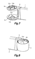
Figure 7 is a perspective view of a first articulation member of the articulation device; -
Figure 8 is a perspective view of a second articulation member of the articulation device; -
Figure 9 is a perspective view of a core of the articulation device; and -
Figure 10 is an exploded perspective view of first and second retention parts, a connecting screw and a nut of the articulation device. - Referring first to
Figure 1 , there is shown a retractable awning arm including afirst arm segment 1 and asecond arm segment 2 having adjacent ends connected to one another by anarticulation device 50 according to an embodiment of the present invention. In the other end of thefirst arm segment 1 there is arranged a firstend articulation element 25 by means of which the awning arm is connected to a load bar (not shown) fixed at a front end of an awning canvas (not shown) and at the other end of thesecond arm segment 2 there is arranged a secondend articulation element 26 by means of which the awning arm is connected to a support (not shown) adjacent to a winding bar (not shown) on which the awning canvas is wound. - By means of the
articulation device 50, the first andsecond arm segments Figures 1 to 4 ) and an extended position (Figures 5 and 6 ). - The
articulation device 50 comprises afirst articulation member 4 fixed to thefirst arm segment 1 and asecond articulation member 5 fixed to thesecond arm segment 2. In the embodiment shown, the first andsecond arm segments second articulation members portions 27, 28 (Figure 2 ) inserted tightly at the adjacent ends of the respective hollow profiles. - As better shown in
Figures 7 and 8 , thefirst articulation member 4 has twofork branches second articulation member 5 has a surroundingwall 9 in the form of a ring, the height of which is only a little less than the distance between said twofork branches second articulation member 5 also has apassage 29 communicating an inner space of the surroundingwall 9 with the hollow inner space of the profile forming thesecond arm segment 2. - In relation to
Figure 3 , thearticulation device 50 further comprises acore 6 configured around said articulation axis E and supported between the twofork branches first articulation member 4. Thiscore 6 is fixed to thefork branches second retention parts Figure 10 which will be described in detail below, and the surroundingwall 9 of thesecond articulation member 5 is arranged surrounding thecore 6. Between the surroundingwall 9 and thecore 6 there is a clearance sized for accommodating aflexible tie element 30 in the form of a flat belt the function of which will be described below. - The first and
second articulation members core 6 and the first andsecond retention parts - For guiding the relative rotation of the first and
second articulation members bearings bearings annular element core 6 and an outerannular element wall 9. To that end, thecore 6 has a pair ofinner seats annular elements respective bearings wall 9 has a pair ofouter seats annular elements respective bearings - As shown in
Figure 2 , the surroundingwall 9 of thesecond articulation members 5 has a protrudingstop 33 interfering with arecess stop 34 of thefirst articulation members 4 for limiting the relative rotation of the first andsecond articulation members Figure 5 ). - The
core 6, which is shown individually inFigure 9 , also has ananchor 7 in which there is attached aterminal 31 of the mentionedflexible tie element 30, and a supportingsurface 8 on which a portion of saidflexible tie element 30 is supported. The pair ofinner seats core 6, and theanchor 7 and the supportingsurface 8 are located between theinner seats - The
flexible tie element 30 is introduced into thesecond arm segment 2 through the mentioned passage 29 (Figure 2 ), and its other end (not shown) opposite the terminal 31 is connected to an elastic member, such as a helical spring (not shown), housed and secured inside thesecond arm segment 2. The tension of said elastic member is transmitted to thecore 6 by theflexible tie element 30 and pushes the first andsecond arm segments -
Figure 10 separately shows the aforementioned first andsecond retention parts wide cover portion pyramidal portion respective cover portion cover portion second retention parts respective fork branch Figure 3 ). Each of the first andsecond retention parts plugs corresponding cover portion - As shown in
Figure 7 , thefork branches first articulation member 4 have formed in a central region thereofrespective openings pyramidal portions second retention parts fork branches recesses plugs respective fork branches second retention parts - Thus, the contact of the
cover portions openings second retention parts openings second fork branches plugs recesses second retention parts second fork branches plugs recesses second retention parts second fork branches pyramidal portions openings - The
core 6 has a pair ofhousings Figure 9 ) open in the opposite axial ends thereof in which thepyramidal portions second retention parts housings pyramidal portions core 6 cannot rotate in relation to the first andsecond retention parts second fork branches first articulation member 4. - The first retention part 13 (
Figures 3 and10 ) has a throughhole 18 aligned with the articulation axis E. This throughhole 18 has an opening at an inner end of thepyramidal portion 13a and an opening with acountersink 18a at an axial end adjacent to an outer side of thefirst retention part 13. The throughhole 18 is sized for receiving the rod of a connectingscrew 17 and thecountersink 18a is sized for housing ahead 17a of the connectingscrew 17 such that thehead 17a does not project from the outer surface of thecover portion 13b. - The second retention part 14 (
Figures 3 and10 ) comprises ahousing 20 and anaxial cavity 21 aligned with the articulation axis E. Theaxial cavity 21 is in the form of a channel with an axial opening at the inner end of thepyramidal portion 14a and a longitudinal opening along thepyramidal portion 14a, and thehousing 20 is in the form of a groove transverse to saidaxial cavity 21 and perpendicular to the articulation axis E with a radial access opening at the same lateral side as the longitudinal opening of theaxial cavity 21. Therefore, the longitudinal opening of theaxial cavity 21 intersects with the radial access opening of the housing 20 (Figure 10 ). Theaxial cavity 21 is sized for receiving an end portion of the rod of the connectingscrew 17, and thehousing 20 is sized for housing anut 19 and configured for retaining saidnut 19 such that it can neither rotate nor move axially in relation to thesecond retention part 14. - To keep the first and
second retention parts screw 17 andnut 19. The connectingscrew 17 is inserted through the throughhole 18 formed in thefirst retention part 13 and screwed in thenut 19 retained in thehousing 20 of thesecond retention part 14. - When the connecting
screw 17 is coupled and tightened to thenut 19, the first andsecond retention parts plugs annular elements respective bearings inner seats core 6. By uncoupling the connectingscrew 17 from thenut 19, the first andsecond retention parts - A person skilled in the art will be capable of introducing modifications and variations to the embodiment shown and described without departing from the scope of the present invention as defined in the attached claims.
Claims (14)
- An articulation device for a retractable awning arm, comprising:a first articulation member (4) fixed to a first arm segment (1) and a second articulation member (5) fixed to a second arm segment (2);a core (6) configured around an articulation axis (E) and supported between two fork branches (4a, 4b) formed in said first articulation member (4), said core (6) having an anchor (7) in which there is attached a terminal (31) of a flexible tie element (30) connected to an elastic member housed inside said second arm segment (2) and a supporting surface (8) on which said flexible tie element (30) is supported;a surrounding wall (9) formed in said second articulation member (5) and arranged around said core (6) with a clearance between both for accommodating the flexible tie element (30);bearing means arranged for guiding a relative rotation of the first and second articulation members (4, 5) around said articulation axis (E);first and second retention parts (13, 14) having respective portions inserted such that they cannot rotate through respective openings (15a, 15b) formed in the fork branches (4a, 4b) and coupled such that they cannot rotate in respective housings (16a, 16b) formed in the core (6); andconnecting means keeping said first and second retention parts (13, 14) connected to one another;characterized in that said connecting means comprise a connecting screw (17) inserted through a through hole (18) formed in the first retention part (13) and screwed in a threaded hole formed in the second retention part (14) or in a nut (19) retained such that it can neither rotate nor move axially in a housing (20) of the second retention part (14).
- The articulation device according to claim 1, characterized in that said through hole (18) is parallel to the articulation axis (E) or is aligned therewith, the second retention part (14) comprises an axial cavity (21) sized for receiving said connecting screw (17), and said housing (20) is in the form of a groove transverse to said axial cavity (21) and perpendicular to the articulation axis (E).
- The articulation device according to claim 2, characterized in that the housing (20) has a radial access opening at a lateral side of the second retention part (14).
- The articulation device according to claim 3, characterized in that said axial cavity (21) has a longitudinal opening at the same lateral side of the second retention part (14) and intersects said radial access opening of the housing (20).
- The articulation device according to claim 1, characterized in that the first and second retention parts (13, 14) have respective pyramidal portions (13a, 14a) and said housings (16a, 16b) of the core (6) are configured for fitting said pyramidal portions (13a, 14a).
- The articulation device according to claim 5, characterized in that said through hole (18) and said axial cavity (21) are positioned at the centre of said respective pyramidal portions (13a, 14a) of the first and second retention parts (13, 14), aligned with the articulation axis (E).
- The articulation device according to claim 1, characterized in that each of the first and second retention parts (13, 14) has at least one protruding plug (22a, 22b) fitting into a respective recess (32a, 32b) formed in the corresponding fork branch (4a, 4b).
- The articulation device according to claim 7, characterized in that each of the first and second retention parts (13, 14) has a cover portion (13b, 14b) configured to be placed on an area of the respective fork branch (4a, 4b) around said opening (15a, 15b), and said plug (22a, 22b) extends from an inner surface of said cover portion (13b, 14b).
- The articulation device according to claim 8, characterized in that each of the first and second retention parts (13, 14) has a plurality of said plugs (22a, 22b) distributed around the articulation axis (E), which are inserted through a plurality of said recesses (32a, 32b) and project from an inner surface of the corresponding fork branch (4a, 4b) for contacting with an inner annular element (11a, 12a) of a corresponding bearing (11, 12) of said bearing means.
- The articulation device according to claim 1, characterized in that said bearing means comprise a pair of bearings (11, 12), each of which comprises an inner annular element (11a, 12a) fixed to the core (6) and an outer annular element (11b, 12b) fixed to said surrounding wall (9).
- The articulation device according to claim 10, characterized in that the core (6) has a pair of inner seats (23a, 23b) configured for receiving said inner annular elements (11a, 12a) of the bearings (11, 12), and said anchor (7) and said supporting surface (8) are located between said pair of inner seats (23a, 23b).
- The articulation device according to claim 10, characterized in that the surrounding wall (9) has a pair of outer seats (24a, 24b) configured for receiving said outer annular elements (11b, 12b) of the pair of bearings (11, 12).
- The articulation device according to claim 1, characterized in that at least one of the bearings (11, 12) is a ball or roller bearing.
- The articulation device according to claim 1, characterized in that said through hole (18) has a countersink (18a) at an axial end adjacent to an outer side of the first retention part (13) sized for housing a head (17a) of the connecting screw (17).
Priority Applications (2)
| Application Number | Priority Date | Filing Date | Title |
|---|---|---|---|
| PT1103711U PT11037T (en) | 2011-12-23 | 2011-12-23 | ARTICULATION DEVICE FOR A RETRACTABLE AERIAL ARM |
| EP11380104.7A EP2607570A1 (en) | 2011-12-23 | 2011-12-23 | Articulation device for a foldable awning arm |
Applications Claiming Priority (1)
| Application Number | Priority Date | Filing Date | Title |
|---|---|---|---|
| EP11380104.7A EP2607570A1 (en) | 2011-12-23 | 2011-12-23 | Articulation device for a foldable awning arm |
Publications (1)
| Publication Number | Publication Date |
|---|---|
| EP2607570A1 true EP2607570A1 (en) | 2013-06-26 |
Family
ID=45531728
Family Applications (1)
| Application Number | Title | Priority Date | Filing Date |
|---|---|---|---|
| EP11380104.7A Pending EP2607570A1 (en) | 2011-12-23 | 2011-12-23 | Articulation device for a foldable awning arm |
Country Status (2)
| Country | Link |
|---|---|
| EP (1) | EP2607570A1 (en) |
| PT (1) | PT11037T (en) |
Cited By (9)
| Publication number | Priority date | Publication date | Assignee | Title |
|---|---|---|---|---|
| EP3235968A1 (en) * | 2016-04-21 | 2017-10-25 | Producciones Mitjavila, S.A.U. | Assembly of pivoting arm for blind and associated installation method |
| KR101840601B1 (en) * | 2017-07-18 | 2018-03-20 | 황영순 | Arm linke of awning using bearing |
| EP3309320A3 (en) * | 2016-10-17 | 2018-09-12 | Rainer Industries, Ltd. | Joint assembly for use in a retractable awning |
| US20190128010A1 (en) * | 2014-09-18 | 2019-05-02 | Oliver Joen-An Ma | Awning apparatus |
| US10343624B2 (en) * | 2017-03-29 | 2019-07-09 | Ford Global Techologies, LLP | Bracket assemblies and vehicles using the same |
| US11613894B2 (en) | 2017-05-08 | 2023-03-28 | ZHUN-AN Ma | Awning apparatus |
| US11891810B2 (en) | 2017-12-08 | 2024-02-06 | ZHUN-AN Ma | Awning apparatus |
| US12173510B2 (en) | 2020-11-04 | 2024-12-24 | Qingdao Activa Shade Inc. | Retractable shade structures |
| EP4663869A1 (en) | 2024-06-10 | 2025-12-17 | TENDACO S.r.l. | Articulation device for an articulated arm for a retractable awning assembly and articulated arm |
Citations (3)
| Publication number | Priority date | Publication date | Assignee | Title |
|---|---|---|---|---|
| WO1998001638A1 (en) | 1996-07-08 | 1998-01-15 | Llaza, Sa | Articulated arm for supporting awnings |
| EP1650373A1 (en) * | 2003-08-01 | 2006-04-26 | Llaza, S.A. | Articulated arm for awnings |
| WO2008037815A1 (en) | 2006-09-27 | 2008-04-03 | Llaza, Sa | Articulation device for awning arm elbow |
-
2011
- 2011-12-23 EP EP11380104.7A patent/EP2607570A1/en active Pending
- 2011-12-23 PT PT1103711U patent/PT11037T/en not_active IP Right Cessation
Patent Citations (3)
| Publication number | Priority date | Publication date | Assignee | Title |
|---|---|---|---|---|
| WO1998001638A1 (en) | 1996-07-08 | 1998-01-15 | Llaza, Sa | Articulated arm for supporting awnings |
| EP1650373A1 (en) * | 2003-08-01 | 2006-04-26 | Llaza, S.A. | Articulated arm for awnings |
| WO2008037815A1 (en) | 2006-09-27 | 2008-04-03 | Llaza, Sa | Articulation device for awning arm elbow |
Cited By (12)
| Publication number | Priority date | Publication date | Assignee | Title |
|---|---|---|---|---|
| US20190128010A1 (en) * | 2014-09-18 | 2019-05-02 | Oliver Joen-An Ma | Awning apparatus |
| US10954689B2 (en) * | 2014-09-18 | 2021-03-23 | Oliver Joen-An Ma | Awning apparatus |
| EP3235968A1 (en) * | 2016-04-21 | 2017-10-25 | Producciones Mitjavila, S.A.U. | Assembly of pivoting arm for blind and associated installation method |
| EP3309320A3 (en) * | 2016-10-17 | 2018-09-12 | Rainer Industries, Ltd. | Joint assembly for use in a retractable awning |
| US10343624B2 (en) * | 2017-03-29 | 2019-07-09 | Ford Global Techologies, LLP | Bracket assemblies and vehicles using the same |
| US11613894B2 (en) | 2017-05-08 | 2023-03-28 | ZHUN-AN Ma | Awning apparatus |
| US12577784B2 (en) | 2017-05-08 | 2026-03-17 | ZHUN-AN Ma | Awning apparatus |
| KR101840601B1 (en) * | 2017-07-18 | 2018-03-20 | 황영순 | Arm linke of awning using bearing |
| WO2019017660A1 (en) * | 2017-07-18 | 2019-01-24 | 황영순 | Awning joint device using bearing |
| US11891810B2 (en) | 2017-12-08 | 2024-02-06 | ZHUN-AN Ma | Awning apparatus |
| US12173510B2 (en) | 2020-11-04 | 2024-12-24 | Qingdao Activa Shade Inc. | Retractable shade structures |
| EP4663869A1 (en) | 2024-06-10 | 2025-12-17 | TENDACO S.r.l. | Articulation device for an articulated arm for a retractable awning assembly and articulated arm |
Also Published As
| Publication number | Publication date |
|---|---|
| PT11037T (en) | 2014-10-30 |
Similar Documents
| Publication | Publication Date | Title |
|---|---|---|
| EP2607570A1 (en) | Articulation device for a foldable awning arm | |
| EP2447439B1 (en) | Pivoting support assembly with locking device for an awning arm | |
| ES2673606T3 (en) | Sensor device and disc brake with a sensor device | |
| EP1650373B1 (en) | Articulated arm for awnings | |
| EP2894289A1 (en) | Shading device for an architectural opening and method for adjusting an end stop position of the shading device | |
| CA2697695A1 (en) | Bearing assembly retaining apparatus and well drilling equipment comprising same | |
| US8627548B2 (en) | Aligning multiple pivot pin system and method therefor | |
| ES2360059T3 (en) | CONNECTION DEVICE. | |
| GB2445045A (en) | Telescopic umbrella shaft | |
| EP2495459A1 (en) | Anchorage device with bearing for lifting, rotating continuously even under load | |
| EP1835101B1 (en) | Hinge for a frame | |
| KR20140070523A (en) | Stabilizer for a lower link of a three-point hitch of a tractor | |
| CA2713001C (en) | Shutter with pull side bar | |
| CN101949245B (en) | Hinge device and producing method thereof | |
| EP2348178B1 (en) | Door retaining device | |
| EP4341578B1 (en) | Swivel connection device | |
| EP2557257A2 (en) | Hinge for a door or window frame or furniture | |
| EP3610722B1 (en) | Double rope pet leash | |
| US20090075797A1 (en) | Roller cover support assembly with roller cover retention spring | |
| WO2014154400A1 (en) | Connection part and power tool including such connection part | |
| EP2489819B1 (en) | Hinge | |
| KR101223619B1 (en) | A safty turning apparatus for a motor fan | |
| DE202011110522U1 (en) | Articulating device for a retractable awning arm | |
| JP5215896B2 (en) | Anti-seismic hinge and door device using the same | |
| EP1990495B1 (en) | Hinge assembly for kitchen covers, wings and doors in general |
Legal Events
| Date | Code | Title | Description |
|---|---|---|---|
| AK | Designated contracting states |
Kind code of ref document: A1 Designated state(s): AL AT BE BG CH CY CZ DE DK EE ES FI FR GB GR HR HU IE IS IT LI LT LU LV MC MK MT NL NO PL PT RO RS SE SI SK SM TR |
|
| AX | Request for extension of the european patent |
Extension state: BA ME |
|
| PUAI | Public reference made under article 153(3) epc to a published international application that has entered the european phase |
Free format text: ORIGINAL CODE: 0009012 |
|
| 110E | Request filed for conversion into a national patent application [according to art. 135 epc] |
Effective date: 20140304 |
|
| 18W | Application withdrawn |
Effective date: 20140304 |
|
| 19U | Interruption of proceedings before grant |
Effective date: 20131105 |
|
| 19W | Proceedings resumed before grant after interruption of proceedings |
Effective date: 20211102 |
|
| STAA | Information on the status of an ep patent application or granted ep patent |
Free format text: STATUS: THE APPLICATION HAS BEEN WITHDRAWN |
|
| STAA | Information on the status of an ep patent application or granted ep patent |
Free format text: STATUS: THE APPLICATION HAS BEEN PUBLISHED |
|
| D18W | Application withdrawn (deleted) | ||
| STAA | Information on the status of an ep patent application or granted ep patent |
Free format text: STATUS: THE APPLICATION IS DEEMED TO BE WITHDRAWN |
|
| 18D | Application deemed to be withdrawn |
Effective date: 20220104 |