EP2607204A2 - Steering apparatus - Google Patents
Steering apparatus Download PDFInfo
- Publication number
- EP2607204A2 EP2607204A2 EP12198814.1A EP12198814A EP2607204A2 EP 2607204 A2 EP2607204 A2 EP 2607204A2 EP 12198814 A EP12198814 A EP 12198814A EP 2607204 A2 EP2607204 A2 EP 2607204A2
- Authority
- EP
- European Patent Office
- Prior art keywords
- rotating member
- rotation transmission
- transmission member
- telescopic
- coupling position
- Prior art date
- Legal status (The legal status is an assumption and is not a legal conclusion. Google has not performed a legal analysis and makes no representation as to the accuracy of the status listed.)
- Withdrawn
Links
Images







Classifications
-
- B—PERFORMING OPERATIONS; TRANSPORTING
- B62—LAND VEHICLES FOR TRAVELLING OTHERWISE THAN ON RAILS
- B62D—MOTOR VEHICLES; TRAILERS
- B62D1/00—Steering controls, i.e. means for initiating a change of direction of the vehicle
- B62D1/02—Steering controls, i.e. means for initiating a change of direction of the vehicle vehicle-mounted
- B62D1/16—Steering columns
- B62D1/18—Steering columns yieldable or adjustable, e.g. tiltable
- B62D1/181—Steering columns yieldable or adjustable, e.g. tiltable with power actuated adjustment, e.g. with position memory
Definitions
- the structure of the steering apparatus that uses the planetary gear mechanism is complicated, which may be a factor that increases the number of components and the size of the apparatus.
- the complicated structure may be a factor that increases the cost.
- the lower shaft 22 extends inside the hollow upper shaft 21.
- the upper shaft 21 moves relative to the lower shaft 22 together with the column tube 40 in an extension-contraction direction T indicated by an arrow T in the drawings.
- the first rotary shaft 310 is coupled to the output shaft 2A of the motor 2.
- the first rotary shaft 310 has a screw gear 311 that rotates together with the rotary shaft 310.
- the second rotary shaft 320 has an input-side rotating member 321.
- the input-side rotating member 321 has a screw gear 322 and a spur gear 323.
- the screw gear 322 is in mesh with the screw gear 311 of the first rotary shaft 310.
- the screw gear 322 and the spur gear 323 rotate together with the second rotary shaft 320.
- the spur gear 323 is in mesh with the rotating member 331.
- the gear fitted portion 183 of the rotary body 180 and the inner periphery of the bevel gear 152 are in mesh with each other by splines.
- the rotary body 180 and the bevel gear 152 rotate together with each other.
- the circlip 176 and the flange portion 182 of the rotary body 180 restrict movement of the bevel gear 152 in the axial direction of the rotary body 180.
- the slider 410 has internal protrusions 411, 412, a support portion 413 and an external protrusion 414.
- the internal protrusions 411, 412 protrude into the housing 11.
- the support portion 413 is supported by the housing 11 and a slider cover 420.
- the external protrusion 414 protrudes from the slider cover 420.
- the external protrusion 414 protrudes outside the housing 11 from an opening 11D of the housing 11.
- the slider 410 is movable in the opening 11D.
- the outer surface of the housing 11 and the slider cover 420 hold the support portion 413 of the slider 410 so that the slider 410 does not to fall off through the opening 11D of the housing 11.
- Screws 430 that are screwed to the housing 11 fix the slider cover 420 to the housing 11.
- step S12 it is determined whether the telescopic operation signal Sb has been detected. When an affirmative determination is made in step S12, the process proceeds to step S13. On the other hand, when a negative determination is made in step S12, the process once ends.
- step S18 the switching current Ik is supplied to the motor 2. That is, the operation for switching the rotation direction of the motor 2 between the reverse direction and the forward direction is executed multiple times.
Landscapes
- Engineering & Computer Science (AREA)
- Chemical & Material Sciences (AREA)
- Combustion & Propulsion (AREA)
- Transportation (AREA)
- Mechanical Engineering (AREA)
- Steering Controls (AREA)
- Transmission Devices (AREA)
Abstract
Description
- The invention relates to a steering apparatus that includes a tilt mechanism that adjusts the position of a steering wheel in the up-down direction of a vehicle, a telescopic mechanism that adjusts the position of the steering wheel in the longitudinal direction of the vehicle, and a drive mechanism that drives at least one of the tilt mechanism and the telescopic mechanism. 2. Discussion of Background
- Japanese Patent Application Publication No.
2007-91171 JP 2007-91171 A - However, the structure of the steering apparatus that uses the planetary gear mechanism is complicated, which may be a factor that increases the number of components and the size of the apparatus. In addition, the complicated structure may be a factor that increases the cost.
- The invention provides a steering apparatus in which power output from a motor is able to be transmitted to at least one of a tilt mechanism and a telescopic mechanism and transmission of the power output from the motor is able to be interrupted with a simple configuration.
- According to a feature of an example of the invention, there is provided a steering apparatus including a tilt mechanism that adjusts a tilt angle of a steering shaft in an up-down direction of a vehicle, a telescopic mechanism that adjusts a telescopic position of the steering shaft in a longitudinal direction of the vehicle, and a drive mechanism that drives the tilt mechanism and the telescopic mechanism, wherein: the drive mechanism includes a motor, a rotating member that is rotated by torque of the motor, a rotation transmission member that is coupled to one of the tilt mechanism and the telescopic mechanism, and a selector mechanism that changes a position of the rotating member relative to the rotation transmission member; the rotating member is coupled to the rotation transmission member when the position of the rotating member relative to the rotation transmission member is a coupling position, and is separated from the rotation transmission member when the position of the rotating member relative to the rotation transmission member is a non-coupling position; one of the rotating member and the rotation transmission member has a protruded portion that protrudes toward the other one of the rotating member and the rotation transmission member, and the other one of the rotating member and the rotation transmission member has a recessed portion into which the protruded portion is inserted; and the selector mechanism inserts the protruded portion into the recessed portion by moving the rotating member located at the non-coupling position to the coupling position, and removes the protruded portion from the recessed portion by moving the rotating member located at the coupling position to the non-coupling position.
- The foregoing and further objects, features and advantages of the invention will become apparent from the following description of example embodiments with reference to the accompanying drawings, wherein like numerals are used to represent like elements and wherein:
-
FIG. 1 is a view that shows the overall configuration of a steering apparatus according to an embodiment of the invention; -
FIG. 2A is a side view that shows the entirety of the steering apparatus as viewed from a position on one side of the steering apparatus; -
FIG. 2B is a side view that shows the entirety of the steering apparatus as viewed from a position on the other side of the steering apparatus; -
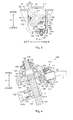
FIG. 3 is a view that shows the configuration of the steering apparatus as viewed from the direction in which a steering shaft extends; -
FIG. 4 is a sectional view that shows the sectional structure of a tilt angle adjustment mechanism; -
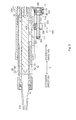
FIG. 5 is a sectional view that shows the sectional structure of a telescopic mechanism; -
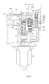
FIG. 6 is a bottom view that shows part of the telescopic mechanism as viewed from a position below the telescopic mechanism; -
FIG. 7 is an exploded perspective view of a selector mechanism; -
FIG. 8 is a perspective view that shows the overall configuration of a power transmission device; -
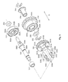
FIG. 9 is a perspective view that shows a support shaft and members provided on the support shaft; -
FIG. 10A is a side view of a rotating member as viewed from a direction perpendicular to the axial direction; -
FIG. 10B is a front view that shows a face of the rotating member, which faces a tilt rotation transmission member; -
FIG. 10C is a back view that shows a face of the rotating member, which faces a telescopic rotation transmission member; -
FIG. 11A is a front view that shows the front structure of a tilt angle adjustment mechanism coupling; -
FIG. 11B is a side view that shows the side structure of the tilt angle adjustment mechanism coupling; -
FIG. 12A is a front view that shows the front structure of a telescopic mechanism coupling; -
FIG. 12B is a side view that shows the side structure of the telescopic mechanism coupling; -
FIG. 13 is a view that shows the configuration of part of the power transmission device; -
FIG. 14 is a view that schematically shows a state where, from among the tilt angle adjustment mechanism and the telescopic mechanism, only the tilt angle adjustment mechanism is driven; -
FIG. 15 is a view that schematically shows a state where, from among the tilt angle adjustment mechanism and the telescopic mechanism, only the telescopic mechanism is driven; -
FIG. 16 is a view that shows a state where the tilt angle adjustment mechanism and the telescopic mechanism are driven at the same time; -
FIG. 17A to FIG. 17C are views showing a rotating member of a steering apparatus according to an alternative embodiment of the invention, whereinFIG. 17A is a side view of the rotating member as viewed from a direction perpendicular to the axial direction,FIG. 17B is a front view that shows a face of the rotating member, which faces the tilt rotation transmission member, andFIG. 17C is a back view that shows a face of the rotating member, which faces the telescopic rotation transmission member; -
FIG. 18 is a view that schematically shows an engaged state where a rotating member is engaged with a rotation transmission member that transmits rotation of the rotating member to at least one of a tilt angle adjustment mechanism and a telescopic mechanism in a steering apparatus according to a comparative example; -
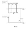
FIG. 19 is a timing chart that shows a change in a first motor current and a change in a second motor current with respect to time; -
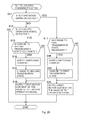
FIG. 20 is a flowchart that shows the procedure of a tilt-telescopic changing process; -
FIG. 21 is a timing chart that shows a change in a first motor current and a change in a second motor current with respect to time in a steering apparatus according to an alternative embodiment of the invention; -
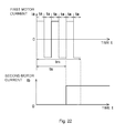
FIG. 22 is a timing chart that shows a change in a first motor current and a change in a second motor current in a steering apparatus according to an alternative embodiment of the invention; -
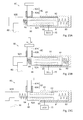
FIG. 23A to FIG. 23C are sectional views that shows the sectional structure of a selector mechanism of a steering apparatus according to an alternative embodiment of the invention, whereinFIG. 23A is a sectional view that shows the sectional structure of the selector mechanism at the time when a selector member is located at a third coupling position,FIG. 23B is a sectional view that shows the sectional structure of the selector mechanism at the time when the selector member is located at a first coupling position, andFIG. 23C is a sectional view that shows the sectional structure of the selector mechanism at the time when the selector member is located at a second coupling position; and -
FIG. 24 is a flowchart that shows the procedure of a position changing process in a steering apparatus according to the alternative embodiment of the invention. - Hereinafter, embodiments of the invention will be described with reference to the accompanying drawings.
- The configuration of a
steering apparatus 1 will be described with reference toFIG. 1 . Thesteering apparatus 1 is a steering column of an electric power steering system that assists an operation for steering a vehicle (not shown). - The
steering apparatus 1 includes ahousing 11, a steeringshaft 20, anassist device 30, acolumn tube 40, asensor housing 12, and aworm housing 13. Thecolumn tube 40 covers the steeringshaft 20. Thesensor housing 12 accommodates a torque sensor 33. Theworm housing 13 accommodates aworm shaft 35 and aworm wheel 37. - In addition, the
steering apparatus 1 includes a tiltangle adjustment mechanism 100, atelescopic mechanism 200, acontrol unit 3 and a drive mechanism 4. The drive mechanism 4 includes apower transmission device 300, aselector mechanism 400, and a tilt-telescopic electric motor 2 (hereinafter, referred to as "motor 2"). - The
housing 11 covers thecolumn tube 40 and the steeringshaft 20. Theassist device 30 applies torque to the steeringshaft 20. The steeringshaft 20 includes anupper shaft 21 and alower shaft 22. A steering wheel (not shown) is connected to theupper shaft 21. Thelower shaft 22 is coupled to theupper shaft 21. - The
lower shaft 22 extends inside the hollowupper shaft 21. Theupper shaft 21 moves relative to thelower shaft 22 together with thecolumn tube 40 in an extension-contraction direction T indicated by an arrow T in the drawings. - The
column tube 40 includes a cylindricalouter tube 41 and a cylindricalinner tube 42 that is coupled to theouter tube 41. Theinner tube 42 is located radially inward of theouter tube 41. Theouter tube 41 and theinner tube 42 move together with each other in the extension-contraction direction T.A rolling bearing 51 that is located between theinner tube 42 and theupper shaft 21 supports the steeringshaft 20 such that the steeringshaft 20 is rotatable, and connects thecolumn tube 40 to the steeringshaft 20. - The
assist device 30 includes atorsion bar 32, the torque sensor 33, an assistelectric motor 34, theworm shaft 35, and theworm wheel 37. Thetorsion bar 22 is connected to the steeringshaft 20 via an input-side shaft member 31. Theworm wheel 37 is connected to thetorsion bar 32 via an output-side shaft member 36. - The input-
side shaft member 31 is located between a lower-side end portion 22B of thelower shaft 22 and an upper-side end portion 32A of thetorsion bar 32. The input-side shaft member 31 fixes thetorsion bar 32 to thelower shaft 22. The input-side shaft member 31 rotates as thetorsion bar 32 is twisted. The torque sensor 33 outputs an electric signal that corresponds to the rotation angle of the input-side shaft member 31. The assistelectric motor 34 rotates theworm shaft 35 on the basis of the torque detected by the torque sensor 33. Theworm shaft 35 is in mesh with theworm wheel 37. Theworm wheel 37 rotates together with the output-side shaft member 36. The output-side shaft member 36 and the lower-side end portion 32B of thetorsion bar 32 are coupled to each other. - The
sensor housing 12 and thehousing 11 are coupled to each other, and theworm housing 13 and thesensor housing 12 are coupled to each other. Abearing 52 is located between theworm housing 13 and the output-side shaft member 36. Thebearing 52 supports the output-side shaft member 36 such that the output-side shaft member 36 is rotatable. - The tilt
angle adjustment mechanism 100 adjusts the tilt angle of the steeringshaft 20, thereby adjusting the position of the steering wheel in the up-down direction of the vehicle. Thetelescopic mechanism 200 adjusts the length of the steeringshaft 20, thereby adjusting the position of the steering wheel in the longitudinal direction of the vehicle. - The
motor 2 has anoutput shaft 2A. Themotor 2 outputs driving force to the tiltangle adjustment mechanism 100 and thetelescopic mechanism 200 via theoutput shaft 2A. Thecontrol unit 3 controls themotor 2 and theselector mechanism 400 on the basis of a user's operation of a switch (not shown) of an operating portion. - The drive mechanism 4 transmits the power output from the
motor 2 to the tiltangle adjustment mechanism 100 and thetelescopic mechanism 200 via thepower transmission device 300, thereby driving the tiltangle adjustment mechanism 100 and thetelescopic mechanism 200. - The
power transmission device 300 transmits the rotation of theoutput shaft 2A to the tiltangle adjustment mechanism 100 and thetelescopic mechanism 200. Theselector mechanism 400 changes a destination to which the driving force output from themotor 2 is transmitted. Note that theselector mechanism 400 may function as a selector mechanism that changes a position of a rotating member with respect to a rotation transmission member. - The
power transmission device 300 includes a firstrotary shaft 310, a secondrotary shaft 320, asupport shaft 330, and a telescopic-side output shaft 340. A rotatingmember 331 is rotatably supported by thesupport shaft 330. The telescopic-side output shaft 340 is connected to thetelescopic mechanism 200. Thesupport shaft 330 also serves as a tilt-side output shaft that is connected to the tiltangle adjustment mechanism 100. - The first
rotary shaft 310 is coupled to theoutput shaft 2A of themotor 2. The firstrotary shaft 310 has ascrew gear 311 that rotates together with therotary shaft 310. The secondrotary shaft 320 has an input-side rotating member 321. The input-side rotating member 321 has ascrew gear 322 and aspur gear 323. Thescrew gear 322 is in mesh with thescrew gear 311 of the firstrotary shaft 310. Thescrew gear 322 and thespur gear 323 rotate together with the secondrotary shaft 320. Thespur gear 323 is in mesh with the rotatingmember 331. - The
support shaft 330 includes the rotatingmember 331, a tiltrotation transmission member 332, and a telescopicrotation transmission member 333. The tiltrotation transmission member 332 is coupled to the tiltangle adjustment mechanism 100. The telescopicrotation transmission member 333 is coupled to thetelescopic mechanism 200. The rotatingmember 331 also serves as a spur gear. The rotatingmember 331, the tiltrotation transmission member 332, and the telescopicrotation transmission member 333 are located on the same axis. The rotatingmember 331 may function as a rotating member that is rotated by torque of a motor. In addition, the tiltrotation transmission member 332 may function as a rotation transmission member that is coupled to a tilt mechanism. In addition, the telescopicrotation transmission member 333 may function as a rotation transmission member that is coupled to a telescopic mechanism. - The rotating
member 331 hascolumnar tilt protrusions 335A and columnartelescopic protrusions 335B. Thetilt protrusions 335A protrude toward the tiltrotation transmission member 332. Thetelescopic protrusions 335B protrude toward the telescopicrotation transmission member 333. Thetilt protrusions 335A and thetelescopic protrusions 335B are arranged parallel to the rotation axis of the rotatingmember 331. The tilt protrusions 335A may function as protruded portions and first protruded portions. Thetelescopic protrusions 335B may function as protruded portions and second protruded portions. - The tilt
rotation transmission member 332 hastilt pin holes 332A that engage with therespective tilt protrusions 335A. Thetilt pin holes 332A face thetilt protrusions 335A, and are arranged parallel to the rotation axis of the rotatingmember 331. The tiltrotation transmission member 332 fixed to thesupport shaft 330 rotates together with thesupport shaft 330. On the other hand, the rotatingmember 331 and the telescopicrotation transmission member 333 are rotatable relative to thesupport shaft 330. Thetilt pin holes 332A may function as recessed portions and first recessed portions. - The telescopic
rotation transmission member 333 has aspur gear 334 and telescopic pin holes 333A. Thespur gear 334 rotates together with therotation transmission member 333. Thetelescopic pin holes 333A engage with the respectivetelescopic protrusions 335B. Thetelescopic pin holes 333A face thetelescopic protrusions 335B, and are arranged parallel to the rotation axis of the rotatingmember 331. Thetelescopic pin holes 333A may function as recessed portions and second recessed portions. - The telescopic-
side output shaft 340 has aspur gear 341 that rotates together with theoutput shaft 340. Thespur gear 341 of the telescopic-side output shaft 340 is in mesh with thespur gear 334 of the telescopicrotation transmission member 333. - The operation of the
assist device 30 will be described with reference toFIG. 1 . The assistelectric motor 34 is driven on the basis of the torque detected by the torque sensor 33. As the assistelectric motor 34 rotates theworm shaft 35, theworm wheel 37 rotates. Thus, the assistelectric motor 34 applies assist force for assisting an operation for steering the vehicle, to the steeringshaft 20 via thetorsion bar 32. In this way, theassist device 30 assists an operation of the steering wheel for steering the vehicle. - The operation of the tilt
angle adjustment mechanism 100 that adjusts the position of the steering wheel in the up-down direction of the vehicle will be described. Themotor 2 applies driving force to the tiltangle adjustment mechanism 100 via thepower transmission device 300. The tiltangle adjustment mechanism 100 causes thesteering apparatus 1 to pivot about a central axis that coincides with a predetermined horizontal axis H by moving thehousing 11 upward or downward. The horizontal axis H is an axis perpendicular to the extension-contraction direction T and the up-down direction V of the vehicle. In this way, the tiltangle adjustment mechanism 100 adjusts the position of the steering wheel in the up-down direction V by causing the steeringshaft 20 to pivot upward or downward about the central axis that coincides with the horizontal axis H. - The operation of the
telescopic mechanism 200 that adjusts the position of the steering wheel in the longitudinal direction of the vehicle will be described. Themotor 2 applies driving force to thetelescopic mechanism 200 via thepower transmission device 300. Thetelescopic mechanism 200 moves the upper-side end portion 21A of theupper shaft 21 in the extension-contraction direction T relative to thelower shaft 22 by moving thecolumn tube 40 in a contraction direction or an extension direction. In this way, thetelescopic mechanism 200 adjusts the position of the steering wheel in the longitudinal direction that coincides with the extension-contraction direction T, by changing the length of the steeringshaft 20 in the extension-contraction direction T. - The configuration of the tilt
angle adjustment mechanism 100 will be described with reference toFIG. 2A, FIG. 2B ,FIG. 3 and FIG. 4. FIG. 3 shows a configuration of thesteering apparatus 1 shown inFIG. 2A , as viewed from the extension direction.FIG. 4 is a sectional view taken along the line S-S inFIG. 3 , including part of the tiltangle adjustment mechanism 100. - As shown in
FIG. 2A and FIG. 2B , the tiltangle adjustment mechanism 100 is located at an upper-side end portion 11A of thehousing 11. The tiltangle adjustment mechanism 100 includes acolumn bracket 110, atilt nut device 120, atilt screw 130, ahousing support device 140, and aflexible shaft 5. Thecolumn bracket 110 covers thehousing 11. Thetilt screw 130 moves relative to thetilt nut device 120. Thehousing support device 140 supports thehousing 11. Thecolumn bracket 110 supports thetilt nut device 120. Thetilt nut device 120 and thehousing support device 140 support thetilt screw 130 such that thetilt screw 130 is rotatable. - As shown in
FIG. 3 , thecolumn bracket 110 includes a vehicle body fittedportion 111, guideportions portions 114. The vehicle body fittedportion 111 is fitted to a vehicle body (not shown). Theguide portions portion 111. Atilt nut 121 is fitted to the tilt nut fittedportions 114. Theguide portions housing support device 140 in the lateral direction that is parallel to the horizontal axis H, and guide movement of thehousing support device 140 in the up-down direction V. The tilt nut fittedportions 114 are located at the lower end portions of theguide portions - As shown in
FIG. 4 , thetilt nut device 120 includes thetilt nut 121, aplug 122, acoil spring 123 and apressing member 124. As shown inFIG. 3 , thetilt nut device 120 includesshaft members 125. - The
tilt nut 121 is located below thehousing support device 140. Thetilt nut 121 has aninternal thread 121A that is screwed to anexternal thread 131 of thetilt screw 130. Thetilt nut 121 accommodates thecoil spring 123 and thepressing member 124. Thecoil spring 123 is located between theplug 122 that is fixed to thetilt nut 121 and thepressing member 124 that is movable in thetilt nut 121. Thecoil spring 123 applies force for pressing thetilt screw 130 against theinternal thread 121A, to thepressing member 124. The pressingmember 124 suppresses generation of noise due to a backlash between theexternal thread 131 of thetilt screw 130 and theinternal thread 121A of thetilt nut 121 by pressing thetilt screw 130 against theinternal thread 121A of thetilt nut 121. Theplug 122 is screwed to aninternal thread 121B of thetilt nut 121. As the amount of screw-in of theplug 122 with respect to theinternal thread 121B changes, a clearance between theplug 122 and thepressing member 124 changes. Therefore, theplug 122 changes force for pressing thetilt screw 130 against theinternal thread 121A. - As shown in
FIG. 3 , theshaft members 125 extending in the lateral direction each extend inside thetilt nut 121 and the tilt nut fittedportions 114 of thecolumn bracket 110. At least one of thetilt nut 121 and a pair of the tilt nut fittedportions 114 is pivotable with respect to theshaft members 125. Thus, thetilt nut device 120 pivots with respect to thecolumn bracket 110 about a central axis that coincides with a horizontal axis H1 shown inFIG. 2A and FIG. 2B . The horizontal axis H1 extends in a direction parallel to the horizontal axis H. - As shown in
FIG. 4 , thetilt screw 130 has a tilt angle adjustmentexternal thread 131, a gear fittedportion 132, a fixingexternal thread 133, aflange portion 134 and a bearing fittedportion 135, which are formed integrally with each other. Abevel gear 151 is fitted to the gear fittedportion 132. Abearing 161 is fitted to the bearing fittedportion 135. - The
external thread 131 that is located in the lower end portion of thetilt screw 130 is screwed to theinternal thread 121A of thetilt nut 121. The gear fittedportion 132, which is located above theexternal thread 131, and the inner periphery of thebevel gear 151 are in mesh with each other by splines. Thus, thetilt screw 130 and thebevel gear 151 rotate together with each other. Theexternal thread 133 that is located in the upper end portion of thetilt screw 130 is fitted to anut 137. Theflange portion 134 that is located above the gear fittedportion 132 restricts movement of thebevel gear 151 in the axial direction of thetilt screw 130, in cooperation with acirclip 136 that is located below the gear fittedportion 132. - As shown in
FIG. 3 , thehousing support device 140 includes ahousing 141 andshaft members 143. Thehousing 141 hasbrackets 142. Theshaft members 143 that extend in the lateral direction each extend inside thecorresponding bracket 142 and the upper-side end portion 11A of thehousing 11. At least one of a pair of thebrackets 142 and the upper-side end portion 11A is pivotable with respect to theshaft members 143. Thus, thehousing support device 140 pivots with respect to thehousing 11 about a central axis that coincides with a horizontal axis H2 shown inFIG. 2A and FIG. 2B . The horizontal axis H2 extends in a direction parallel to the horizontal axes H, H1. - As shown in
FIG. 4 , thehousing support device 140, which supports thetilt screw 130 in cooperation with thetilt nut device 120 such that thetilt screw 130 is rotatable, includes thebearing 161, abearing 162, and a flexibleshaft support mechanism 170. Thebearings tilt screw 130. The flexibleshaft support mechanism 170 supports theflexible shaft 5 that is coupled to thesupport shaft 330. - The
bearing 161 supports the columnar bearing fittedportion 135 that is located above theflange portion 134. The bearing 161 bears a radial load of thetilt screw 130. The bearing 162 that is located above thebearing 161 is located below thenut 137. Thebearing 162 supports anannular member 138 that is located between the bearing 162 and thenut 137 in the axial direction of thetilt screw 130. Theannular member 138 functions as a washer. The bearing 162 bears an axial load of thetilt screw 130 by supporting theannular member 138. - The flexible
shaft support mechanism 170 includes arotary body 180, a rotarybody support cover 171, abearing 172, abolt 173,annular members circlip 176. Therotary body 180 is fixed to an output-side end portion of theflexible shaft 5. The rotarybody support cover 171 supports therotary body 180 such that therotary body 180 is rotatable. - The
rotary body 180 has a columnar bearing fittedportion 181, aflange portion 182 and a gear fitted portion 183, which are formed integrally with each other. Thebearing 172 is fitted to the bearing fittedportion 181. Theflange portion 182 is located near the bearing fittedportion 181. Abevel gear 152 is fitted to the gear fitted portion 183. - The rotary
body support cover 171 supports therotary body 180 via thebearing 172. The bearing 172 located inside the rotarybody support cover 171 supports the columnar bearing fittedportion 181. Thebolt 173 fixes the rotarybody support cover 171 to thehousing 141. Theannular members flange portion 182 in the axial direction of therotary body 180. Theannular member 175 has elasticity that acts in the axial direction of therotary body 180. The bearing 172 that bears a radial load of therotary body 180 also bears an axial load of therotary body 180 by supporting theflange portion 182 via theannular members rotary body 180 and the inner periphery of thebevel gear 152 are in mesh with each other by splines. Thus, therotary body 180 and thebevel gear 152 rotate together with each other. Thecirclip 176 and theflange portion 182 of therotary body 180 restrict movement of thebevel gear 152 in the axial direction of therotary body 180. - The
flexible shaft 5 is a metal wire that rotates while allowing its deflection. As shown inFIG. 2B , an input-side end portion of theflexible shaft 5 rotates together with arotary body 190 that is coupled to the support shaft 330 (seeFIG. 1 ). Thus, as thesupport shaft 330 rotates, therotary body 190 and theflexible shaft 5 rotate. - Next, the operation of the tilt
angle adjustment mechanism 100 will be described. As the support shaft 330 (seeFIG. 1 ) of thepower transmission device 300 rotates, the flexible shaft 5 (seeFIG. 4 ) rotates. Therotary body 180 rotates in accordance with the rotation of theflexible shaft 5. The bevel gears 152, 151 transmit the rotation of therotary body 180 to thetilt screw 130. As thetilt screw 130 rotates relative to thetilt nut 121, thetilt nut 121 moves upward or downward. That is, the distance from thetilt nut device 120 to thehousing support device 140 changes in the axial direction of thetilt screw 130. As the clearance between thetilt nut device 120 and thehousing support device 140 changes in this way, thehousing 11 and the steeringshaft 20 pivots upward or downward inside thecolumn bracket 110 about the pivot axis that coincides with the horizontal axis H (seeFIG. 2 ). - The configuration of the
telescopic mechanism 200 will be described with reference toFIG. 5. FIG. 5 shows a section that is parallel to the extension-contraction direction T, and that includes part of thetelescopic mechanism 200. As shown inFIG. 5 , thetelescopic mechanism 200 is located at a lower-side end portion 41B of theouter tube 41. Thetelescopic mechanism 200 includes atelescopic nut device 210 and atelescopic screw 220. Thetelescopic nut device 210 is fixed to the outer periphery of thecolumn tube 40. Thetelescopic screw 220 moves relative to thetelescopic nut device 210. Thehousing 11 has an opening 11C so that thetelescopic nut device 210 that is located on the outer periphery of thecolumn tube 40 does not contact thehousing 11. That is, thetelescopic nut device 210 protrudes from the opening 11C of thehousing 11 toward the outside of thehousing 11. - The
telescopic nut device 210 includes atelescopic nut 211, a nutaccommodating case 212, and acase fixing bolt 213. Thetelescopic nut 211 has aninternal thread 211A. The nutaccommodating case 212 accommodates thetelescopic nut 211. Thecase fixing bolt 213 fixes thenut accommodating case 212 to thecolumn tube 40. Thecase fixing bolt 213 passes through thenut accommodating case 212, and is fitted to the lower-side end portion 41B of theouter tube 41. - The
telescopic screw 220 passes through thetelescopic nut 211 and thenut accommodating case 212. Thetelescopic screw 220 has anexternal thread 221 and anexternal thread 222 that are formed integrally with thetelescopic screw 220. Theexternal thread 221 is screwed to theinternal thread 211A of thetelescopic nut 211. Theexternal thread 222 is located at a distal end portion in the extension direction. Anut 223 is screwed to theexternal thread 222. Thenut 223 restricts movement of thetelescopic nut device 210 relative to thetelescopic screw 220 in the extension direction. - Next, the operation of the
telescopic mechanism 200 will be described. As the telescopic-side output shaft 340 (seeFIG. 1 ) of thepower transmission device 300 rotates, the telescopic screw 220 (seeFIG. 5 ) rotates. As thetelescopic screw 220 rotates relative to thetelescopic nut 211, thetelescopic nut 211 moves in the extension direction or the contraction direction. That is, theouter tube 41 to which thetelescopic nut device 210 is fixed moves in the extension-contraction direction T together with theinner tube 42. As thecolumn tube 40 that is connected to theupper shaft 21 moves in this way, theupper shaft 21 moves relative to thelower shaft 22 in the extension-contraction direction T. - The configuration of the
selector mechanism 400 will be described with reference toFIG. 6 to FIG. 8 .FIG. 7 is an exploded view of theselector mechanism 400 shown inFIG. 6 .FIG. 8 shows a state where thehousing 11, and the like, shown inFIG. 6 are removed. The arrow A in the drawings indicates the axial direction of the rotatingmember 331. The axial direction A is a direction parallel to the rotation axis of the rotatingmember 331. - As shown in
FIG. 6 , theselector mechanism 400 is located at the lower-side end portion 11B of thehousing 11. As shown inFIG. 7 , theselector mechanism 400 includes aslider 410 and an electric motor (selector motor, not shown). Theslider 410 moves the rotatingmember 331 of thepower transmission device 300 in the axial direction A. The electric motor moves theslider 410. A compact motor that outputs power smaller than that of themotor 2 is employed as the electric motor that moves theslider 410. - The
slider 410 hasinternal protrusions support portion 413 and anexternal protrusion 414. Theinternal protrusions housing 11. Thesupport portion 413 is supported by thehousing 11 and aslider cover 420. Theexternal protrusion 414 protrudes from theslider cover 420. Theexternal protrusion 414 protrudes outside thehousing 11 from anopening 11D of thehousing 11. Theslider 410 is movable in theopening 11D. The outer surface of thehousing 11 and theslider cover 420 hold thesupport portion 413 of theslider 410 so that theslider 410 does not to fall off through theopening 11D of thehousing 11.Screws 430 that are screwed to thehousing 11 fix theslider cover 420 to thehousing 11. - As shown in
FIG. 8 , theinternal protrusions member 331 in the axial direction A. By moving theslider 410 in the axial direction A, theinternal protrusion 411 presses aside face 331C of the rotatingmember 331, which faces the tiltrotation transmission member 332, toward the telescopicrotation transmission member 333. Theinternal protrusion 412 presses aside face 331D of the rotatingmember 331, which faces the telescopicrotation transmission member 333, toward the tiltrotation transmission member 332. In this way, theselector mechanism 400 changes the position of the rotatingmember 331 relative to the tiltrotation transmission member 332 and the telescopicrotation transmission member 333 by moving the rotatingmember 331 provided between the tiltrotation transmission member 332 and the telescopicrotation transmission member 333 in the axial direction A. - The structure of the
power transmission device 300 will be described in detail with reference toFIG. 8 to FIG. 13 .FIG. 9 shows a state where the members supported by thesupport shaft 330 are removed from thesupport shaft 330.FIG. 13 shows a state where the input-side rotating member 321 of the secondrotary shaft 320 is in mesh with the rotatingmember 331. - As shown in
FIG. 8 , the firstrotary shaft 310 and the secondrotary shaft 320 are arranged in a skew position. The secondrotary shaft 320, thesupport shaft 330 and the telescopic-side output shaft 340 are parallel to each other. The firstrotary shaft 310 to which theoutput shaft 2A of themotor 2 is connected is provided withbearings screw gear 311 is located between thebearings rotary shaft 320 is provided withbearings side rotating member 321 is located between thebearings support shaft 330 is provided withbearings member 331, the tiltrotation transmission member 332 and the telescopicrotation transmission member 333 are located between thebearings side output shaft 340 is provided withbearings spur gear 341 is located between thebearings - The housing 11 (see
FIG. 6 ) accommodates thepower transmission device 300 that includes thebearings motor housing 14 coupled to thehousing 11 accommodates themotor 2 that is coupled to thepower transmission device 300. A bearinghousing 15 coupled to thehousing 11 accommodates thebearings - As shown in
FIG. 9 , thesupport shaft 330 has an intermediate member fittedportion 330A, a tilt member fittedportion 330B, a telescopic member fittedportion 330C, and aflange portion 330D, which are formed integrally with each other. The rotatingmember 331 is fitted to the intermediate member fittedportion 330A. The tiltrotation transmission member 332 is fitted to the tilt member fittedportion 330B. The telescopicrotation transmission member 333 is fitted to the telescopic member fittedportion 330C. -
Bushes nut 353, and aspacer 356 are provided with thesupport shaft 330 as components that are connected to thesupport shaft 330. Thecylindrical bush 351 is fitted to the intermediate member fittedportion 330A of thesupport shaft 330. Thesnap ring 352 is located between the intermediate member fittedportion 330A and the telescopic member fittedportion 330C. Thesnap ring 352 restricts movement of the rotatingmember 331 in the axial direction A together with theflange portion 330D. Thenut 353 is fitted to the tilt member fittedportion 330B. Thenut 353 restricts movement of the tiltrotation transmission member 332 in the axial direction A together with theflange portion 330D. Thecylindrical bush 354 is fitted to the telescopic member fittedportion 330C of thesupport shaft 330. Part of thebush 354 also serves as a spacer between the telescopicrotation transmission member 333 and thesnap ring 355. Thesnap ring 355 restricts movement of the telescopicrotation transmission member 333 in the axial direction A together with thesnap ring 352. Thespacer 356 is located between the telescopicrotation transmission member 333 and thesnap ring 352. Thespacer 356 and thebush 354 prevent the telescopicrotation transmission member 333 from contacting the snap rings 352, 355. -
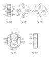
FIG. 10A shows a side view of the rotatingmember 331 as viewed from a direction perpendicular to the axial direction.FIG. 10B is a front view that shows a face of the rotatingmember 331, which faces the tilt rotation transmission member.FIG. 10C is a back view that shows a face of the rotatingmember 331, which faces the telescopic rotation transmission member. - The rotating
member 331 is fitted to the intermediate member fittedportion 330A. The rotatingmember 331 has press-fittingholes 331A and aninsertion hole 331B. Fourpins 335 are respectively press-fitted into the press-fittingholes 331A. Theinsertion hole 331B is larger in size than the outside diameter of thebush 351. The intermediate member fittedportion 330A of thesupport shaft 330 is fitted into theinsertion hole 331B via thebush 351. Thebush 351 is located between the intermediate member fittedportion 330A and the inner periphery of the rotatingmember 331, which defines theinsertion hole 331B. Thebush 351 functions as a bearing for the rotatingmember 331. -
FIG. 11A is a front view of the tiltrotation transmission member 332.FIG. 11B shows a side view of the tiltrotation transmission member 332. The tiltrotation transmission member 332 is fitted to the tilt member fittedportion 330B. The tiltrotation transmission member 332 has thetilt pin holes 332A and aninsertion hole 332B. Theinsertion hole 332B engages with the tilt member fittedportion 330B. Eachtilt pin hole 332A has a shape along a circle having a center that coincides with the axis that extends in the axial direction A. The tilt member fittedportion 330B of thesupport shaft 330 is fitted to theinsertion hole 332B. Because theinsertion hole 332B and the tilt member fittedportion 330B are engaged with each other, the tiltrotation transmission member 332 does not rotate relative to thesupport shaft 330. -
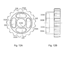
FIG. 12A shows a front view of the telescopicrotation transmission member 333.FIG. 12B shows a side view of the telescopicrotation transmission member 333. The telescopicrotation transmission member 333 is fitted to the telescopic member fittedportion 330C. The telescopicrotation transmission member 333 has thetelescopic pin holes 333A and aninsertion hole 333B that is larger in size than the outside diameter of thebush 354. Eachtelescopic pin hole 333A has a shape along a circle having a center that coincides with the axis that extends in the axial direction A. The telescopic member fittedportion 330C of thesupport shaft 330 is fitted to theinsertion hole 333B via thebush 354. Thebush 354 is located between the telescopic member fittedportion 330C and the inner periphery of the telescopicrotation transmission member 333, which defines theinsertion hole 333B. Thebush 354 functions as a bearing for the telescopicrotation transmission member 333. - The
pins 335 are fitted into the respective press-fittingholes 331A of the rotatingmember 331. Eachpin 335 is a protrusion that has thetilt protrusion 335A and thetelescopic protrusion 335B that are formed as a single-piece member and made of the same material. That is, thetilt protrusion 335A and thetelescopic protrusion 335B are formed by thecorresponding pin 335. At the time of press-fitting eachpin 335 into the press-fittinghole 331A, eachpin 335 has aflange portion 335C in order to restrict movement of thepin 335 relative to the rotatingmember 331 in the axial direction A. - As shown in
FIG. 13 , thesupport shaft 330 supports the rotatingmember 331, which is in mesh with thespur gear 323, such that the rotatingmember 331 is movable in the axial direction A. Aflange portion 324 of the secondrotary shaft 320 and anut 325 fitted to the secondrotary shaft 320 sandwich the input-side rotating member 321 fitted to the secondrotary shaft 320. In this way, the input-side rotating member 321 is fixed to the secondrotary shaft 320. - A size L1 of each
pin 335 in the axial direction A, that is, a distance from the distal end of eachtilt protrusion 335A to the distal end of the correspondingtelescopic protrusion 335B, is larger than a length L2 of a clearance between the tiltrotation transmission member 332 and the telescopicrotation transmission member 333, which face each other in the axial direction A. Thus, in thepower transmission device 300, it is possible to achieve a state where thetilt protrusions 335A are inserted into the respectivetilt pin holes 332A and thetelescopic protrusions 335B are inserted into the respective telescopic pin holes 333A. - A length L7 of each
tilt protrusion 335A in the axial direction A, which is inserted into the correspondingtilt pin hole 332A, is smaller than a movable length L3 over which the rotatingmember 331 is movable in the axial direction A between the tiltrotation transmission member 332 and the telescopicrotation transmission member 333. Thus, in thepower transmission device 300, it is possible to achieve a state where thetilt protrusions 335A are not inserted into the tilt pin holes 332A. The movable length L3 over which the rotatingmember 331 is movable in the axial direction A corresponds to a length that is obtained by subtracting a size L4 of the rotatingmember 331 in the axial direction A and a length L5 of eachflange portion 335C in the axial direction A, which is not inserted in the pin holes 332A, 333A, from the length L2 of the clearance between the tiltrotation transmission member 332 and the telescopicrotation transmission member 333. - A length L6 of each
telescopic protrusion 335B in the axial direction A, which is inserted into the correspondingtelescopic pin hole 333A, is also smaller than the movable length L3 over which the rotatingmember 331 is movable in the axial direction between the tiltrotation transmission member 332 and the telescopicrotation transmission member 333. Thus, in thepower transmission device 300, it is possible to achieve a state where thetelescopic protrusions 335B are not inserted into the telescopic pin holes 333A. - When the rotating
member 331 rotates in a state where thetilt protrusions 335A are inserted into the tilt pin holes 332A, the rotatingmember 331 and the tiltrotation transmission member 332 are coupled to each other. Similarly, when the rotatingmember 331 rotates in a state where thetelescopic protrusions 335B are inserted into the telescopic pin holes 333A, the rotatingmember 331 and the telescopicrotation transmission member 333 are coupled to each other. - The
slider 410 of theselector mechanism 400 shown inFIG. 8 moves the rotatingmember 331 to one of a first coupling position, a second coupling position and a double coupling position described below. - (1) The first coupling position is a position at which the rotating
member 331 is coupled to only the tiltrotation transmission member 332 from among the tiltrotation transmission member 332 and the telescopicrotation transmission member 333. That is, the first coupling position corresponds to a coupling position at which the rotatingmember 331 is coupled to the tiltrotation transmission member 332 and a non-coupling position at which the rotatingmember 331 is separated from the telescopicrotation transmission member 333. - (2) The second coupling position is a position at which the rotating
member 331 is coupled to only the telescopicrotation transmission member 333 from among the tiltrotation transmission member 332 and the telescopicrotation transmission member 333. That is, the second coupling position corresponds to a coupling position at which the rotatingmember 331 is coupled to the telescopicrotation transmission member 333 and a non-coupling position at which the rotatingmember 331 is separated from the tiltrotation transmission member 332. - (3) The double coupling position is a position at which the rotating
member 331 is coupled to both the tiltrotation transmission member 332 and the telescopicrotation transmission member 333. - That is, the
selector mechanism 400 changes the coupling state among the following tilt coupling state, telescopic coupling state and double coupling state by moving the rotatingmember 331. - (1) The tilt coupling state is a state where the rotating
member 331 is located at the first coupling position, and therefore the rotatingmember 331 and the tiltrotation transmission member 332 are coupled to each other and the rotatingmember 331 and the telescopicrotation transmission member 333 are not coupled to each other. - (2) The telescopic coupling state is a state where the rotating
member 331 is located at the second coupling position, and therefore the rotatingmember 331 and the telescopicrotation transmission member 333 are coupled to each other and the rotatingmember 331 and the tiltrotation transmission member 332 are not coupled to each other. - (3) The double coupling state is a state where the rotating
member 331 is located at the double coupling position, and therefore the rotatingmember 331 and both the tiltrotation transmission member 332 and the telescopicrotation transmission member 333 are coupled to each other. - A transmission path of the driving force output from the
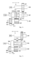
motor 2 will be described with reference toFIG. 14 to FIG. 16 .FIG. 14 shows the tilt coupling state where the motor 2 (seeFIG. 8 ) drives the tiltangle adjustment mechanism 100.FIG. 15 shows the telescopic coupling state where themotor 2 drives thetelescopic mechanism 200.FIG. 16 shows the double coupling state where themotor 2 drives the tilt angle adjustment mechanism and the telescopic mechanism at the same time. - As shown in
FIG. 14 , in the tilt coupling state, the rotatingmember 331 and the tiltrotation transmission member 332 are coupled to each other. Therefore, the rotation of theoutput shaft 2A of themotor 2 is transmitted to the flexible shaft 5 (seeFIG. 8 ) of the tiltangle adjustment mechanism 100 via the firstrotary shaft 310, the secondrotary shaft 320, the rotatingmember 331, the tiltrotation transmission member 332 and thesupport shaft 330. - As shown in
FIG. 15 , in the telescopic coupling state, the rotatingmember 331 and the telescopicrotation transmission member 333 are coupled to each other. Therefore, the rotation of theoutput shaft 2A of themotor 2 is transmitted to the telescopic screw 220 (seeFIG. 8 ) of thetelescopic mechanism 200 via the firstrotary shaft 310, the secondrotary shaft 320, the rotatingmember 331, the telescopicrotation transmission member 333 and the telescopic-side output shaft 340. - As shown in
FIG. 16 , in the double coupling state, the rotation of theoutput shaft 2A of themotor 2 is transmitted to the firstrotary shaft 310, the secondrotary shaft 320 and the rotatingmember 331. Then, the rotation is transmitted from the rotatingmember 331 to theflexible shaft 5 via the tiltrotation transmission member 332 and thesupport shaft 330, and is transmitted from the rotatingmember 331 to thetelescopic screw 220 via the telescopicrotation transmission member 333 and the telescopic-side output shaft 340. - When the
output shaft 2A of themotor 2 rotates in one direction in the double coupling state, the tiltangle adjustment mechanism 100 pivots the steeringshaft 20 upward about a central axis that coincides with the horizontal axis H, and thetelescopic mechanism 200 reduces the length of the steeringshaft 20. When theoutput shaft 2A of themotor 2 rotates in the other direction, the tiltangle adjustment mechanism 100 pivots the steeringshaft 20 downward about the central axis that coincides with the horizontal axis H, and thetelescopic mechanism 200 extends the length of the steeringshaft 20. - Next, the operation of the
selector mechanism 400 will be described. Theselector mechanism 400 changes a destination to which the power output from themotor 2 is transmitted, by moving the rotatingmember 331 in the axial direction A. That is, theselector mechanism 400 inserts thetilt protrusions 335A into thetilt pin holes 332A by bringing the rotatingmember 331 close to the tiltrotation transmission member 332, thus coupling the rotatingmember 331 and the tiltrotation transmission member 332 to each other. At this time, thepower transmission device 300 transmits the power output from themotor 2 to the tiltangle adjustment mechanism 100. - The
selector mechanism 400 inserts thetelescopic protrusions 335B into thetelescopic pin holes 333A by bringing the rotatingmember 331 close to the telescopicrotation transmission member 333, thus coupling the rotatingmember 331 and the telescopicrotation transmission member 333 to each other. At this time, thepower transmission device 300 transmits the power output from themotor 2 to thetelescopic mechanism 200. - The
selector mechanism 400 inserts thetilt protrusions 335A into thetilt pin holes 332A and inserts thetelescopic protrusions 335B into the telescopic pin holes 333A, thus coupling the rotatingmember 331 and both the tiltrotation transmission member 332 and the telescopicrotation transmission member 333 to each other. At this time, thepower transmission device 300 transmits the power output from themotor 2 to both the tiltangle adjustment mechanism 100 and thetelescopic mechanism 200. - When the rotation of the rotating
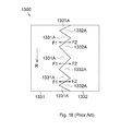
member 331 is transmitted to the tiltrotation transmission member 332 or the telescopicrotation transmission member 333, it is possible to reduce thrust force that acts in a direction parallel to the rotation axis as compared with apower transmission device 1300 according to a comparative example shown inFIG. 18 . - The comparative example will be described with reference to
FIG. 18 . Thepower transmission device 1300 includes a rotatingmember 1331 and arotation transmission member 1332. The rotation of an output shaft (not shown) of a motor is transmitted to the rotatingmember 1331. Therotation transmission member 1332 transmits the rotation of the rotatingmember 1331 to one of a tilt angle adjustment mechanism (not shown) and a telescopic mechanism (not shown). The rotatingmember 1331 and therotation transmission member 1332 each are formed of a crown gear. The rotatingmember 1331 hastriangular teeth 1331A that protrude in a direction parallel to the rotation axis of the rotatingmember 1331. Similarly, therotation transmission member 1332 hastriangular teeth 1332A that protrude in a direction parallel to the rotation axis of the rotatingmember 1331. When theteeth member 1331 and therotation transmission member 1332 are coupled to each other. At this time, theteeth member 1331. Therefore, as the rotatingmember 1331 rotates in a direction indicated by an arrow R, thrust force indicated by an arrow F1 in the drawing acts on the rotatingmember 1331, and thrust force indicated by an arrow F2 in the drawing acts on therotation transmission member 1332. Thus, there occur thrust forces that separate the rotatingmember 1331 and therotation transmission member 1332 from each other. Therefore, as the rotatingmember 1331 slips, thepower transmission device 1300 is not able to reliably transmit the rotation of the output shaft of the motor to the tilt angle adjustment mechanism or the telescopic mechanism. In addition, when thepower transmission device 1300 includes an actuator (not shown) that is used to keep a state where the rotatingmember 1331 and therotation transmission member 1332 are coupled to each other in order to prevent slip of the rotatingmember 1331, the configuration becomes complex. - On the other hand, in the
power transmission device 300 according to the present embodiment, thetilt protrusions 335A and the tilt pin holes 332A are engageable with each other at faces that are parallel to the rotation axis of the rotatingmember 331. Thus, thetilt protrusions 335A and thetilt pin holes 332A do not cause thrust force to act on the rotatingmember 331 and therotation transmission member 332. In addition, thetelescopic protrusions 335B and the telescopic pin holes 333A are engageable with each other at faces that are parallel to the rotation axis of the rotatingmember 331. Thus, thetelescopic protrusions 335B and thetelescopic pin holes 333A do not cause thrust force to act on the rotatingmember 331 and the telescopicrotation transmission member 333. - Next, the operation of the
control unit 3 will be described with reference toFIG. 19 . When thecontrol unit 3 detects a telescopic operation signal Sb (seeFIG. 1 ) at the first coupling position, thecontrol unit 3 determines that the mechanism that is driven needs to be changed from the tiltangle adjustment mechanism 100 to thetelescopic mechanism 200. When thecontrol unit 3 detects a tilt operation signal Sa (seeFIG. 1 ) at the second coupling position, thecontrol unit 3 determines that the mechanism that is driven needs to be changed from thetelescopic mechanism 200 to the tiltangle adjustment mechanism 100. - When the
control unit 3 determines that the mechanism that is driven needs to be changed to the tiltangle adjustment mechanism 100, thecontrol unit 3 supplies a first motor current Ia of which the sign is inverted at a predetermined time interval ta as a switching current Ik. That is, where the reverse rotation and forward rotation of the motor (first motor) 2, caused by the first motor current Ia, are set as a rotation direction alternate switching operation, the rotation direction alternate switching operation is repeatedly performed a predetermined number of times. - The reverse rotation of the
motor 2 indicates rotation in a direction opposite to a direction in which themotor 2 has been rotating in a state before the above determination result is obtained. That is, when themotor 2 has been rotating in a first rotation direction in the previous state, rotation in a second rotation direction corresponds to the reverse rotation. When themotor 2 has been rotating in the second rotation direction in the previous state, rotation in the first rotation direction corresponds to the reverse rotation. - The forward rotation of the
motor 2 indicates rotation in the same direction as the direction in which themotor 2 has been rotating in a state before the above determination result is obtained. That is, when themotor 2 has been rotating in the first rotation direction in the previous state, rotation in the first rotation direction corresponds to the forward rotation. When themotor 2 has been rotating in the second rotation direction in the previous state, rotation in the second rotation direction corresponds to the forward rotation. - The
control unit 3 continues supplying the switching current Ik over a predetermined period tm. When a predetermined time interval tb has elapsed after supply of the switching current Ik is completed, a positive second motor current Ib that moves the rotatingmember 331 toward the tiltrotation transmission member 332 is supplied to the changing motor (second motor, not shown). After the mechanism that is driven is changed to the tiltangle adjustment mechanism 100, supply of the positive second motor current Ib is stopped. - After supply of the positive second motor current Ib is stopped, when the tilt operation signal Sa has been continuously detected and an increase in tilt angle is indicated as an adjustment direction, the positive first motor current Ia is supplied to the
motor 2. - After supply of the positive second motor current Ib is stopped, when the tilt operation signal Sa has been continuously detected and a reduction in tilt angle is indicated as an adjustment direction, the negative first motor current Ia is supplied to the
motor 2. The absolute value of the first motor current Ia at the time when the tilt angle is increased or reduced is set to the same magnitude. - When the
control unit 3 determines that the mechanism that is driven needs to be changed to thetelescopic mechanism 200, the first motor current Ia of which the sign is inverted at the predetermined time interval ta as in the case at the time when the mechanism that is driven is changed to the tiltangle adjustment mechanism 100 is supplied as the switching current Ik. After the predetermined time interval tb has elapsed after supply of the switching current Ik is completed, the negative second motor current Ib that moves the rotatingmember 331 toward the telescopicrotation transmission member 333 is supplied. - After supply of the negative second motor current Ib is stopped, when the telescopic operation signal Sb has been continuously detected and forward displacement of a telescopic position is indicated as an adjustment direction, the positive first motor current Ia is supplied to the
motor 2. - After supply of the negative second motor current Ib is stopped, when the telescopic operation signal Sb has been continuously detected and reverse displacement of the telescopic position is indicated as an adjustment direction, the negative first motor current Ia is supplied to the
motor 2. The absolute value of the first motor current Ia at the time when the telescopic position is moved forward or rearward is set to the same magnitude. - When the
control unit 3 has detected the tilt operation signal Sa at the first coupling position or when thecontrol unit 3 has detected the telescopic operation signal Sb at the second coupling position, thecontrol unit 3 determines that the mechanism that is driven does not need to be changed. When thecontrol unit 3 determines that the mechanism that is driven does not need to be changed, thecontrol unit 3 supplies the first motor current Ia having a sign corresponding to the adjustment direction indicated by the tilt operation signal Sa or the telescopic operation signal Sb without supplying the switching current Ik and the second motor current Ib. - The details of a tilt-telescopic changing process will be described with reference to
FIG. 20 . Thecontrol unit 3 repeatedly executes this process at a predetermined control cycle. That is, after the process has reached the end step, execution of the process of step S11 is suspended until the predetermined control cycle elapses, and the process of step S11 is executed again when the predetermined control cycle has elapsed. - In step S11, it is determined whether the tilt operation signal Sa has been detected. When an affirmative determination is made in step S11, the process proceeds to step S17. On the other hand, when a negative determination is made in step S11, the process proceeds to step S12.
- In step S12, it is determined whether the telescopic operation signal Sb has been detected. When an affirmative determination is made in step S12, the process proceeds to step S13. On the other hand, when a negative determination is made in step S12, the process once ends.
- In step S13, it is determined whether it is necessary to change the coupling position from the first coupling position to the second coupling position. That is, it is determined whether the mechanism that is driven needs to be changed from the tilt
angle adjustment mechanism 100 to thetelescopic mechanism 200. When an affirmative determination is made in step S13, the process proceeds to step S14. On the other hand, when a negative determination is made in step S13, the process skips step S14 and step S15 and proceeds to step S16. - In step S14, the switching current Ik is supplied to the
motor 2. That is, the operation for switching the rotation direction of themotor 2 between the reverse direction and the forward direction is executed multiple times. - In step S15, the negative second motor current Ib is supplied to the changing motor. That is, the position of the rotating
member 331 is changed from the first coupling position to the second coupling position. - In step S16, the first motor current Ia having a sign corresponding to the adjustment direction of the
telescopic mechanism 200, which is indicated by the telescopic operation signal Sb, is supplied to themotor 2. That is, thetelescopic mechanism 200 is driven in a direction based on operation of the operating unit (not shown). - In step S17, it is determined whether it is necessary to change from the second coupling position to the first coupling position. That is, it is determined whether the mechanism that is driven needs to be changed from the
telescopic mechanism 200 to the tiltangle adjustment mechanism 100. When an affirmative determination is made in step S17, the process proceeds to step S18. On the other hand, when a negative determination is made in step S17, the process skips step S18 and step S19 and proceeds to step S20. - In step S18, the switching current Ik is supplied to the
motor 2. That is, the operation for switching the rotation direction of themotor 2 between the reverse direction and the forward direction is executed multiple times. - In step S19, the positive second motor current Ib is supplied to the changing motor. That is, the position of the rotating
member 331 is changed from the second coupling position to the first coupling position. - In step S20, the first motor current Ia having a sign corresponding to the adjustment direction of the tilt
angle adjustment mechanism 100, which is indicated by the tilt operation signal Sa, is supplied to themotor 2. That is, the tiltangle adjustment mechanism 100 is driven in a direction based on operation of the operating unit. - The
steering apparatus 1 according to the present embodiment has the following advantageous effects. - (1) The drive mechanism 4 includes the
motor 2, the rotatingmember 331, the tiltrotation transmission member 332 and theselector mechanism 400 that changes the position of the rotatingmember 331 relative to the tiltrotation transmission member 332. The rotatingmember 331 is coupled to the tiltrotation transmission member 332 when the position of the rotatingmember 331 relative to the tiltrotation transmission member 332 is the first coupling position, and therotation member 331 is separated from the tiltrotation transmission member 332 when the position of the rotatingmember 331 relative to the tiltrotation transmission member 332 is the second coupling position. The rotatingmember 331 has thetilt protrusions 335A that protrude toward the tiltrotation transmission member 332, and the tiltrotation transmission member 332 has the tilt pin holes 332A into which thetilt protrusions 335A are inserted. Theselector mechanism 400 moves the rotatingmember 331 located at the second coupling position to the first coupling position, thereby inserting thetilt protrusions 335A into the tilt pin holes 332A, and moves the rotatingmember 331 located at the first coupling position to the second coupling position, thereby removing thetilt protrusions 335A from the tilt pin holes 332A. Thus, as theselector mechanism 400 inserts thetilt protrusions 335A into the tilt pin holes 332A, thetilt protrusions 335A and the tilt pin holes 332A are engageable with each other, that is, the rotatingmember 331 is coupled to the tiltrotation transmission member 332. When the rotatingmember 331 is located at the first coupling position, the tiltrotation transmission member 332 rotates together with the rotatingmember 331. Thus, the power output from themotor 2 is transmitted to the tiltangle adjustment mechanism 100. Therefore, in comparison with the configuration in which the planetary gear mechanism is used, it is possible to transmit the rotation of themotor 2 to the tiltangle adjustment mechanism 100 with a simple configuration. In addition, as theselector mechanism 400 removes thetilt protrusions 335A from the tilt pin holes 332A, the rotatingmember 331 is separated from the tiltrotation transmission member 332. Therefore, it is possible to interrupt transmission of the power output from themotor 2. - (2) The drive mechanism 4 includes the
motor 2, the rotatingmember 331, the telescopicrotation transmission member 333 and theselector mechanism 400 that changes the position of the rotatingmember 331 relative to the telescopicrotation transmission member 333. The rotatingmember 331 is coupled to the telescopicrotation transmission member 333 when the position of the rotatingmember 331 relative to the telescopicrotation transmission member 333 is the second coupling position, and the rotatingmember 331 is separated from the telescopicrotation transmission member 333 when the position of the rotatingmember 331 relative to the telescopicrotation transmission member 333 is the first coupling position. The rotatingmember 331 has thetelescopic protrusions 335B that protrude toward the telescopicrotation transmission member 333, and the telescopicrotation transmission member 333 has the telescopic pin holes 333A into which thetelescopic protrusions 335B are inserted. Theselector mechanism 400 moves the rotatingmember 331 located at the first coupling position to the second coupling position, thereby inserting thetelescopic protrusions 335B into the telescopic pin holes 333A, and moves the rotatingmember 331 located at the second coupling position to the first coupling position, thereby removing thetelescopic protrusions 335B from the telescopic pin holes 333A. Thus, as theselector mechanism 400 inserts thetelescopic protrusions 335B into the telescopic pin holes 333A, thetelescopic protrusions 335B and the telescopic pin holes 333A are engageable with each other, that is, the rotatingmember 331 is coupled to the telescopicrotation transmission member 333. When the rotatingmember 331 is located at the second coupling position, the telescopicrotation transmission member 333 rotates together with the rotatingmember 331, the power output from themotor 2 is transmitted to thetelescopic mechanism 200. Therefore, in comparison with the configuration in which the planetary gear mechanism is used, it is possible to transmit the rotation of themotor 2 to thetelescopic mechanism 200 with a simple configuration. In addition, as theselector mechanism 400 removes thetelescopic protrusions 335B from the telescopic pin holes 333A, the rotatingmember 331 is separated from the telescopicrotation transmission member 333. Therefore, it is possible to interrupt transmission of the power output from themotor 2. - (3) The rotating
member 331 has thetilt protrusions 335A that protrude toward the tiltrotation transmission member 332 and thetelescopic protrusions 335B that protrude toward the telescopicrotation transmission member 333, and thetilt protrusions 335A and thetelescopic protrusions 335B are formed of the columnar pins 335. Therefore, in comparison with the case where thetilt protrusions 335A and thetelescopic protrusions 335B are formed of separate components, it is possible to reduce the number of components. - (4) The rotating
member 331 is coupled to both the tiltrotation transmission member 332 and the telescopicrotation transmission member 333 when the rotatingmember 331 is located at the double coupling position, and theselector mechanism 400 moves the rotatingmember 331 located at the second coupling position to the first coupling position or the double coupling position, and moves the rotatingmember 331 located at the first coupling position to the second coupling position or the double coupling position. Thus, as theselector mechanism 400 moves the rotatingmember 331 located at the first coupling position or the second coupling position to the double coupling position, it is possible to transmit the power output from themotor 2 to the tiltangle adjustment mechanism 100 and thetelescopic mechanism 200 at the same time. - (5) When the rotating
member 331 is located at the double coupling position and themotor 2 rotates in one direction, the tiltangle adjustment mechanism 100 moves the position of the steering wheel upward in the up-down direction of the vehicle, and thetelescopic mechanism 200 moves the position of the steering wheel toward the front of the vehicle in the longitudinal direction of the vehicle. Therefore, for example, in comparison with the configuration where the position of the steering wheel is moved upward in the up-down direction of the vehicle and the steering wheel is moved toward the rear of the vehicle by rotating themotor 2 in one direction, it is possible to quickly increase the clearance between the driver and thesteering apparatus 1. - (6) When the rotating
member 331 and themotor 2 complete adjustment of the tilt angle or adjustment of the telescopic position, the rotatingmember 331 and themotor 2 are connected to each other via the secondrotary shaft 320. With this configuration, friction force of a portion at which the rotatingmember 331 and thespur gear 323 are in mesh with each other acts as resistance against force that changes the tilt angle or telescopic position of the steeringshaft 20. Therefore, in comparison with the configuration where the rotatingmember 331 and themotor 2 are not connected to each other, tilt rotation resistance and telescopic rotation resistance increase. Thus, a change in tilt angle or telescopic position of the steeringshaft 20 in response to an input load is less likely to occur. - (7) The
control unit 3 executes at least one of control A and control B. In the control A, when the rotatingmember 331 has been moved to the tiltrotation transmission member 332 and is located at the first coupling position, themotor 2 is rotated in the reverse direction and then the rotatingmember 331 is moved to the telescopicrotation transmission member 333 and the coupling position of the rotatingmember 331 is changed to the second coupling position. In the control B, when the rotatingmember 331 has been moved to the telescopicrotation transmission member 333 and is located at the second coupling position, themotor 2 is rotated in the reverse direction and then the coupling position of the rotatingmember 331 is changed to the first coupling position. - When the
motor 2 rotates in the reverse direction at the first coupling position, force that changes the rotation direction of the rotatingmember 331 relative to the tiltrotation transmission member 332 to a direction opposite to the direction in which themotor 2 has been rotated is applied to the rotatingmember 331. Therefore, when the rotatingmember 331 is inclined relative to the tiltrotation transmission member 332, it is highly likely that the inclination will be eliminated. Similarly, when the rotatingmember 331 is inclined relative to the telescopicrotation transmission member 333, it is highly likely that the inclination will be eliminated. When the inclination between the tiltrotation transmission member 332 or telescopicrotation transmission member 333 and the rotatingmember 331 is eliminated, application of a large load to a changing electric motor that is required to execute the control A or the control B is suppressed, in comparison with the case where the inclination is not eliminated. - (8) In at least one of the control A and the control B, which is executed by the
control unit 3, when an operation for rotating themotor 2 in the reverse direction and the forward direction is set as a rotation direction alternate switching operation, the rotation direction alternate switching operation is executed multiple times and then the rotatingmember 331 is moved toward the tiltrotation transmission member 332 or the telescopicrotation transmission member 333. - The inclination of the rotating
member 331 with respect to the tiltrotation transmission member 332 or telescopicrotation transmission member 333 may not be eliminated only by rotating themotor 2 in the reverse direction once. With this configuration, because the rotation direction alternate switching operation of themotor 2 is performed multiple times, it is further highly likely that the inclination will be eliminated. - The scope of the invention includes an embodiment other than the above-described embodiment. Hereinafter, embodiments alternative to the above-described embodiment will be described as other embodiments of the invention. The following alternative embodiments may be implemented in combination with each other.
- The rotating
member 331 according to the above-described embodiment has thecolumnar tilt protrusions 335A andtelescopic protrusions 335B. On the other hand, as shown inFIG. 17A , a rotatingmember 336 according to an alternative embodiment may have rectangular parallelepiped-shapedtilt protrusions 336A and rectangular parallelepiped-shapedtelescopic protrusions 336B. Thetilt protrusions 336A are located at aside face 336C of the rotatingmember 336, which faces a tilt rotation transmission member (not shown). Thetelescopic protrusions 336B are located at aside face 336D of the rotatingmember 336, which faces a telescopic rotation transmission member (not shown). The rotatingmember 336 has aninsertion hole 336E into which thesupport shaft 330 is inserted. - As shown in
FIG. 17B , the fourtilt protrusions 336A that extend in the radial direction of the rotatingmember 336 are arranged at equal intervals along the circumference of theinsertion hole 336E. As shown inFIG. 17C , the fourtelescopic protrusions 336B that extend in the radial direction of the rotatingmember 336 are arranged at equal intervals along the circumference of theinsertion hole 336E. The tilt rotation transmission member has recessed portions (not shown) having faces parallel to the rotation axis of the rotatingmember 336. The tilt protrusions 336A are fitted to the recessed portions. The telescopic rotation transmission member has recessed portions (not shown) having faces parallel to the rotation axis of the rotatingmember 336. Thetelescopic protrusions 336B are fitted to the recessed portions. With the above configuration, the selector mechanism 400 (FIG. 8 ) is placed in the tilt coupling state by inserting thetilt protrusions 336A into the recessed portions of the tilt rotation transmission member. In addition, theselector mechanism 400 is placed in the telescopic coupling state by inserting thetelescopic protrusions 336B into the recessed portions of the telescopic rotation transmission member. That is, the protruded portions are not limited to thecolumnar protrusions member 331 may be changed. - In the
steering apparatus 1 according to the above-described embodiment (FIG. 1 ), the rotatingmember 331 has thetilt protrusions 335A, and the tiltrotation transmission member 332 has the tilt pin holes 332A. On the other hand, in a steering apparatus according to an alternative embodiment, the rotatingmember 331 may have tilt pin holes (not shown), and the tiltrotation transmission member 332 may have tilt pins (not shown). That is, the rotatingmember 331 may include recessed portions having faces parallel to the rotation axis of the rotatingmember 331, and the tiltrotation transmission member 332 may include protruded portions having faces parallel to the rotation axis of the rotatingmember 331. - In the
steering apparatus 1 according to the above-described embodiment (FIG. 1 ), the rotatingmember 331 has thetelescopic protrusions 335B, and the telescopicrotation transmission member 333 has the telescopic pin holes 333A. On the other hand, in a steering apparatus according to an alternative embodiment, the rotatingmember 331 may have tilt pin holes (not shown), and the telescopicrotation transmission member 333 may have telescopic pins (not shown). That is, the rotatingmember 331 may include recessed portions having faces parallel to the rotation axis of the rotatingmember 331, and the telescopicrotation transmission member 333 may include protruded portions having faces parallel to the rotation axis of the rotatingmember 331. - The
support shaft 330 according to the above-described embodiment (FIG. 1 ) supports the telescopicrotation transmission member 333 and the rotatingmember 331 such that the telescopicrotation transmission member 333 and the rotatingmember 331 are rotatable relative to each other, and rotates together with the tiltrotation transmission member 332. On the other hand, thesupport shaft 330 according to an alternative embodiment may support the tiltrotation transmission member 332 and the rotatingmember 331 such that the tiltrotation transmission member 332 and the rotatingmember 331 are rotatable relative to each other, and may rotate together with the telescopicrotation transmission member 333. That is, the configuration of thesupport shaft 330 that is not fixed to the tiltrotation transmission member 332 may be employed. - The
selector mechanism 400 according to the above-described embodiment (FIG. 1 ) includes the electric motor that moves theslider 410. On the other hand, theselector mechanism 400 according to an alternative embodiment may be configured to change the position of the rotatingmember 331 by moving theslider 410 with force of an operator who operates theexternal protrusion 414 of theslider 410. - The
selector mechanism 400 according to the above-described embodiment (FIG. 1 ) couples the rotatingmember 331 to the tiltrotation transmission member 332 and the telescopicrotation transmission member 333 at the same time by changing the coupling state to the double coupling state. On the other hand, theselector mechanism 400 according to an alternative embodiment may change the coupling state among the tilt coupling state, the telescopic coupling state and a non-coupling state where the rotatingmember 331 is coupled to neither the tiltrotation transmission member 332 nor the telescopicrotation transmission member 333. In this case, the size L1 of eachpin 335 in the axial direction A is smaller than the length L2 of the clearance between the tiltrotation transmission member 332 and the telescopicrotation transmission member 333 that faces each other in the axial direction A. - In the above-described embodiment, the switching current Ik of which the sign is inverted at the time interval ta is supplied. Alternatively, there may be employed a configuration in which the sign of the first motor current Ia immediately before the drive mechanism is switched is stored and then the first motor current Ia that is supplied during the time interval ta with a sign that is definitely opposite to the stored sign is set as the switching current Ik at the time when the drive mechanism is switched.
FIG. 21 shows the switching current Ik at the time when the positive first motor current Ia is supplied before the mechanism that is driven is changed to the tiltangle adjustment mechanism 100, and shows the positive second motor current Ib that is supplied at the time when the time interval tb has elapsed after the switching current Ik is supplied in order to change the mechanism that is driven to the tiltangle adjustment mechanism 100. - In the above-described embodiment, the rotating
member 331 is moved by supplying the second motor current Ib at the time when the time interval tb has elapsed from when supply of the switching current Ik is completed. Alternatively, the rotatingmember 331 may be moved by supplying the second motor current Ib while the switching current Ik is being supplied. That is, the rotatingmember 331 may be moved while the rotation direction alternate switching operation of themotor 2 is being executed.FIG. 22 is a timing chart at the time when supply of the positive second motor current Ib is started when a time interval ts that is shorter than a predetermined period tm has elapsed from a start of supply of the switching current Ik. When the transmission state of the rotatingmember 331 is changed while the rotation direction alternate switching operation of themotor 2 is being executed, start of the operation for changing the transmission state is advanced in comparison with the case where changing the transmission state of the rotatingmember 331 is started after the rotation direction alternate switching operation of themotor 2 is executed. - As shown in
FIG. 23 , a selector mechanism may be configured to move aselector member 60 with the use of asolenoid 90. With this configuration, theselector mechanism 80 changes a selected position of theselector member 60 to one of a first coupling position to a third coupling position. - The
selector mechanism 80 includes abody housing 81, an operatingunit 82 and acoil spring 83. Thebody housing 81 accommodates thesolenoid 90. The operatingunit 82 changes the position of thesolenoid 90 relative to thebody housing 81. Thecoil spring 83 applies force, which moves thesolenoid 90, to thesolenoid 90. - The
body housing 81 has a cylindrical shape of which one end is open. The operatingunit 82 includes apush button 82A and asupport member 82B that supports movement of thepush button 82A. Thecoil spring 83 connects the bottom of thebody housing 81 to an end portion of thesolenoid 90, which faces the bottom of thebody housing 81. - The
solenoid 90 includes asolenoid housing 91, amovable member 92, acoil 93, and acoil spring 94. Thesolenoid housing 91 constitutes a body. Themovable member 92 moves relative to thesolenoid housing 91. Thecoil 93 moves themovable member 92. Thecoil spring 94 supplies themovable member 92 with force in a direction opposite to the direction in which themovable member 92 is moved by thecoil 93. - The
movable member 92 has ashaft 92A and aslider 92B. Theshaft 92A receives moving force with which theshaft 92A is moved relative to thesolenoid housing 91 by thecoil 93. Theslider 92B is connected to theselector member 60. Theslider 92B is fixed to the distal end portion of theshaft 92A. - The
coil spring 94 connects an end portion of thesolenoid housing 91, on theslider 92B side, and theslider 92B to each other. AnECU 15 supplies electric power to thecoil 93 at the time of an engine start of the vehicle. During an engine stop, supply of electric power is stopped. - The positional relationship among the components of the
selector mechanism 80 will be described. Hereinafter, the position of thesolenoid 90 at the time when thepush button 82A is in an off state, that is, when thecoil spring 83 has a natural length, is referred to as a first solenoid position, and the position of thesolenoid 90 at the time when thepush button 82A is in an on state, that is, when thecoil spring 83 is compressed, is referred to as a second solenoid position. The position of theslider 92B at the time when electric power is supplied to thecoil 93, that is, when thecoil spring 94 has a natural length, is referred to as a first slider position, and the position of theslider 92B at the time when no electric power is supplied to thecoil 93, that is, when thecoil spring 94 is compressed, is referred to as a second slider position. - As shown in
FIG. 23A , in theselector mechanism 80, when thesolenoid 90 is in the first solenoid position and theslider 92B is in the second slider position, theselector mechanism 80 sets the selected position of theselector member 60 to the third coupling position. As shown inFIG. 23B , in theselector mechanism 80, when thesolenoid 90 is in the second solenoid position and theslider 92B is in the second slider position, theselector mechanism 80 sets the selected position of theselector member 60 to the first coupling position. As shown inFIG. 23C , in theselector mechanism 80, when thesolenoid 90 is in the first solenoid position and theslider 92B is in the first slider position, theselector mechanism 80 sets the selected position of theselector member 60 to the second coupling position. - The procedure of position changing process will be described with reference to
FIG. 24 . In this process, it is determined whether a condition for changing the selected position of theselector member 60 to the third coupling position is satisfied, on the basis of conditions in the following step S111 and step S112. In step S111, it is determined whether adjustment of the tilt angle or adjustment of the telescopic position is completed. In step S112, it is determined whether the selected position of theselector member 60 is the third coupling position. In step S112, when a target rotation angle at the time when the selected position of theselector member 60 is the third coupling position coincides with a detected rotation angle, it is determined that the selected position of theselector member 60 is the third coupling position. - When an affirmative determination is made in step S111 and a negative determination is made in step S112, it is determined that the condition for changing the selected position of the
selector member 60 to the third coupling position is satisfied. In step S113, the selected position of theselector member 60 is changed to the third coupling position. - On the other hand, when a negative determination is made in step S111 or when an affirmative determination is made in each of step S111 and step S112, it is determined that the condition for changing the selected position of the
selector member 60 to the third coupling position is not satisfied. - The
steering apparatus 1 according to the present embodiment has the following advantageous effects. (1) When adjustment of the tilt angle is completed, thecontrol unit 15 changes the selected position of theselector member 60 from the first coupling position to the third coupling position. When adjustment of the telescopic position is completed, thecontrol unit 15 changes the selected position of theselector member 60 from the second coupling position to the third coupling position. Thus, a change in tilt angle or telescopic position in response to an input load is less likely to occur. Unlike in the configuration where friction force is increased by increasing the outside diameter of a screw shaft of a tilt mechanism, the inside diameter of a nut of the tilt mechanism, the outside diameter of a screw shaft of a telescopic mechanism and the inside diameter of a nut of the telescopic mechanism, it is possible to use a compact driving electric motor. - (2) The
steering wheel 2 may receive an excess load from the driver. An example of an excess load is a load generated at the time when the driver contacts thesteering wheel 2 as a result of a collision of the vehicle. On the other hand, when an excess load is input into thesteering wheel 2, the driver may receive excessively large reaction force from thesteering wheel 2. Therefore, when an excess load acts on thesteering wheel 2, desirably, the telescopic position significantly changes to an opposite side with respect to a driver seat, unlike in the case where a normal input load acts on thesteering wheel 2. - The
steering apparatus 1 includes thetilt mechanism 12 and thetelescopic mechanism 13. In thetilt mechanism 12, the tilt angle is increased upward in response to an input load. In thetelescopic mechanism 13, the telescopic position is displaced forward in response to an input load. With this configuration, when an excess load acts on thesteering wheel 2, a increase in the tilt angle downward is suppressed, so the component of force for displacing the telescopic position forward increases. Thus, the telescopic position is significantly displaced forward. Therefore, excessively large reaction force is less likely to act on the driver. - (3) The
selector member 60 and the drivingelectric motor 14 are connected to each other via afirst transmission mechanism 21 when adjustment of the tilt angle or adjustment of the telescopic position is completed. With this configuration, friction force of a portion at which theselector member 60 and a spur gear 21C are in mesh with each other acts as resistance against force that changes the tilt angle or telescopic position of the steeringshaft 20. Therefore, in comparison with the configuration where theselector member 60 and the drivingelectric motor 14 are not connected to each other, tilt rotation resistance and telescopic rotation resistance increase. Thus, a change in tilt angle or telescopic position of the steeringshaft 20 in response to an input load is less likely to occur.
Claims (11)
- A steering apparatus including a tilt mechanism that adjusts a tilt angle of a steering shaft in an up-down direction of a vehicle, a telescopic mechanism that adjusts a telescopic position of the steering shaft in a longitudinal direction of the vehicle, and a drive mechanism that drives the tilt mechanism and the telescopic mechanism, characterized in that:the drive mechanism includes a motor, a rotating member that is rotated by torque of the motor, a rotation transmission member that is coupled to one of the tilt mechanism and the telescopic mechanism, and a selector mechanism that changes a position of the rotating member relative to the rotation transmission member;the rotating member is coupled to the rotation transmission member when the position of the rotating member relative to the rotation transmission member is a coupling position, and is separated from the rotation transmission member when the position of the rotating member relative to the rotation transmission member is a non-coupling position;one of the rotating member and the rotation transmission member has a protruded portion that protrudes toward the other one of the rotating member and the rotation transmission member, and the other one of the rotating member and the rotation transmission member has a recessed portion into which the protruded portion is inserted; andthe selector mechanism inserts the protruded portion into the recessed portion by moving the rotating member located at the non-coupling position to the coupling position, and removes the protruded portion from the recessed portion by moving the rotating member located at the coupling position to the non-coupling position.
- The steering apparatus according to claim 1, wherein:the drive mechanism includes a first rotation transmission member that is connected to the tilt mechanism and a second rotation transmission member that is connected to the telescopic mechanism, as the rotation transmission member;the rotating member is located between the first rotation transmission member and the second rotation transmission member;the rotating member is coupled to only the first rotation transmission member from among the first rotation transmission member and the second rotation transmission member when the rotating member is located at a first coupling position, and is coupled to only the second rotation transmission member from among the first rotation transmission member and the second rotation transmission member when the rotating member is located at a second coupling position; andbetween the first rotation transmission member and the second rotation transmission member, the selector mechanism moves the rotating member located at the second coupling position to the first coupling position and moves the rotating member located at the first coupling position to the second coupling position.
- The steering apparatus according to claim 2, wherein:one of the rotating member and the first rotation transmission member has a first protruded portion that serves as the protruded portion, and the other one of the rotating member and the first rotation transmission member has a first recessed portion that serves as the recessed portion; andthe selector mechanism inserts the first protruded portion into the first recessed portion by moving the rotating member located at the second coupling position to the first coupling position, and removes the first protruded portion from the first recessed portion by moving the rotating member located at the first coupling position to the second coupling position.
- The steering apparatus according to claim 3, wherein:one of the rotating member and the second rotation transmission member has a second protruded portion that serves as the protruded portion, and the other one of the rotating member and the second rotation transmission member has a second recessed portion that serves as the recessed portion; andthe selector mechanism inserts the second protruded portion into the second recessed portion by moving the rotating member located at the first coupling position to the second coupling position, and removes the second protruded portion from the second recessed portion by moving the rotating member located at the second coupling position to the first coupling position.
- The steering apparatus according to claim 4, wherein:the rotating member has the first protruded portion that protrudes toward the first rotation transmission member and the second protruded portion that protrudes toward the second rotation transmission member, as the protruded portion, andthe first protruded portion and the second protruded portion each are formed of a columnar pin.
- The steering apparatus according to any one of claims 2 to 5, wherein:the rotating member is coupled to both the first rotation transmission member and the second rotation transmission member when the rotating member is located at a double coupling position; andbetween the first rotation transmission member and the second rotation transmission member, the selector mechanism moves the rotating member located at the second coupling position to the first coupling position or the double coupling position and moves the rotating member located at the first coupling position to the second coupling position or the double coupling position.
- The steering apparatus according to claim 6, wherein
when the rotating member is located at the double coupling position and the motor rotates in one direction, the tilt mechanism increases the tilt angle of the steering shaft upward and the telescopic mechanism moves the telescopic position of the steering shaft toward a front of the vehicle. - The steering apparatus according to claim 1, wherein
the drive mechanism includes an input rotation transmission member that transmits rotation of an output shaft of the motor to the rotating member, and the rotating member has an external gear that is in mesh with an external gear of the input rotation transmission member. - The steering apparatus according to claim 2, wherein
there is executed at least one of control A for moving the rotating member to the second coupling position after rotating the motor in a reverse direction when the rotating member is located at the first coupling position and control B for moving the rotating member to the first coupling position after rotating the motor in the reverse direction when the rotating member is located at the second coupling position. - The steering apparatus according to claim 9, wherein
at least one of the control A and the control B moves the rotating member to the second coupling position or the first coupling position after a rotation direction alternate switching operation which is an operation for rotating the motor alternately in the reverse direction and a forward direction is executed multiple times or while the rotation direction alternate switching operation is being executed. - The steering apparatus according to claim 2, wherein
a third coupling position at which the rotating member is coupled to the first coupling member and the second coupling member is further provided, and the selector mechanism moves the rotating member to the third coupling position when at least one of adjustment of the tilt angle of the steering shaft and adjustment of the telescopic position of the steering shaft is completed.
Applications Claiming Priority (4)
| Application Number | Priority Date | Filing Date | Title |
|---|---|---|---|
| JP2011280308A JP2013129320A (en) | 2011-12-21 | 2011-12-21 | Steering device |
| JP2011280309A JP2013129321A (en) | 2011-12-21 | 2011-12-21 | Steering apparatus |
| JP2011280306A JP2013130247A (en) | 2011-12-21 | 2011-12-21 | Control device of drive device |
| JP2011280305A JP2013129319A (en) | 2011-12-21 | 2011-12-21 | Steering device |
Publications (2)
| Publication Number | Publication Date |
|---|---|
| EP2607204A2 true EP2607204A2 (en) | 2013-06-26 |
| EP2607204A3 EP2607204A3 (en) | 2014-01-15 |
Family
ID=47631208
Family Applications (1)
| Application Number | Title | Priority Date | Filing Date |
|---|---|---|---|
| EP12198814.1A Withdrawn EP2607204A3 (en) | 2011-12-21 | 2012-12-21 | Steering apparatus |
Country Status (3)
| Country | Link |
|---|---|
| US (1) | US20130160597A1 (en) |
| EP (1) | EP2607204A3 (en) |
| CN (1) | CN103223971A (en) |
Cited By (1)
| Publication number | Priority date | Publication date | Assignee | Title |
|---|---|---|---|---|
| EP3870495B1 (en) * | 2018-10-24 | 2024-12-04 | thyssenkrupp Presta AG | Steering column for a motor vehicle |
Families Citing this family (19)
| Publication number | Priority date | Publication date | Assignee | Title |
|---|---|---|---|---|
| JP6212915B2 (en) * | 2013-04-10 | 2017-10-18 | アイシン精機株式会社 | Vehicle steering device |
| JP6067484B2 (en) * | 2013-05-29 | 2017-01-25 | 富士機工株式会社 | Steering column device |
| DE102014117802A1 (en) * | 2014-12-03 | 2016-06-09 | Trw Automotive Gmbh | Power steering for vehicles |
| US9739361B2 (en) * | 2015-09-29 | 2017-08-22 | Steering Solutions Ip Holding Corporation | Vehicle steering column assembly and method of assembling |
| CN105416382B (en) * | 2015-12-25 | 2017-11-24 | 孙乙钦 | A kind of car steering tube column adjustment control cylinder |
| US10654509B2 (en) * | 2017-01-30 | 2020-05-19 | Thyssenkrupp Presta Ag | Adjustment drive for a steering column, steering column that is adjustable by motor for a motor vehicle and method for setting a bearing arrangement of an adjustment drive |
| DE102017201379A1 (en) | 2017-01-30 | 2018-08-02 | Thyssenkrupp Ag | Motor-adjustable steering column for a motor vehicle and adjustment drive for a steering column |
| DE102017120669B4 (en) * | 2017-09-07 | 2025-03-20 | Zf Automotive Germany Gmbh | Steering column assembly for a motor vehicle and steering system |
| CN107650999A (en) * | 2017-09-23 | 2018-02-02 | 芜湖雪影实业有限公司 | A kind of automobile steering dish structure |
| US10919558B2 (en) * | 2017-12-19 | 2021-02-16 | Mando Corporation | Steering apparatus for vehicle |
| JP7380548B2 (en) | 2018-04-04 | 2023-11-15 | 株式会社ジェイテクト | steering device |
| JP2021525671A (en) * | 2018-05-31 | 2021-09-27 | ビーワイディー カンパニー リミテッド | Steering column and vehicle |
| WO2020011771A1 (en) | 2018-07-11 | 2020-01-16 | Thyssenkrupp Presta Ag | Adjustment drive for a steering column, motor-adjustable steering column for a motor vehicle, and method for adjusting a bearing assembly of an adjustment drive |
| DE102019209680A1 (en) * | 2018-07-30 | 2020-01-30 | Robert Bosch Engineering And Business Solutions Private Limited | ACTUATOR UNIT FOR A STEERING WHEEL OF A VEHICLE |
| WO2020054560A1 (en) * | 2018-09-11 | 2020-03-19 | 日本精工株式会社 | Assist mechanism and electric power steering device |
| DE102019125796A1 (en) * | 2019-09-25 | 2021-03-25 | Audi Ag | Steering wheel arrangement |
| JP7404986B2 (en) * | 2020-04-15 | 2023-12-26 | 株式会社ジェイテクト | steering device |
| CN115551764A (en) * | 2020-05-07 | 2022-12-30 | 蒂森克虏伯普利斯坦股份公司 | Steering column for a motor vehicle |
| CN117561195A (en) * | 2021-06-25 | 2024-02-13 | 株式会社捷太格特 | Steering column device |
Citations (3)
| Publication number | Priority date | Publication date | Assignee | Title |
|---|---|---|---|---|
| JP2007091171A (en) | 2005-09-30 | 2007-04-12 | Fuji Kiko Co Ltd | Electric tilt telescopic steering column |
| CA2528557A1 (en) * | 2005-11-30 | 2007-05-30 | Tm 4 Inc. | Multi-position clutch |
| US20090199667A1 (en) * | 2008-02-11 | 2009-08-13 | Delphi Technologies, Inc. | Modular power actuator |
Family Cites Families (9)
| Publication number | Priority date | Publication date | Assignee | Title |
|---|---|---|---|---|
| US3396600A (en) * | 1966-10-11 | 1968-08-13 | Gen Motors Corp | Power operated tilt and telescope steering assembly |
| US4785684A (en) * | 1986-09-30 | 1988-11-22 | Aisin Seiki Kabushiki Kaisha | Vehicle steering mechanism |
| JP2638871B2 (en) * | 1988-01-26 | 1997-08-06 | アイシン精機株式会社 | Steering device |
| JP2001199350A (en) * | 2000-01-17 | 2001-07-24 | Toyota Motor Corp | Vehicle steering device |
| US6460427B1 (en) * | 2002-01-28 | 2002-10-08 | Ford Global Technologies, Inc. | Adjustment linkage for tilting and telescoping a steering column assembly |
| KR100580534B1 (en) * | 2005-01-03 | 2006-05-15 | 현대자동차주식회사 | Tilt and telescopic mode change type motor-driven steering system using gears |
| US7503234B2 (en) * | 2005-05-26 | 2009-03-17 | Delphi Technologies, Inc. | One lever tilt and telescope mechanism |
| US8376402B2 (en) * | 2010-01-07 | 2013-02-19 | Hyundai Motor Company | Lower type motor driven column apparatus |
| KR101219934B1 (en) * | 2010-11-08 | 2013-01-08 | 현대자동차주식회사 | United type Motor Driven Power Steering System |
-
2012
- 2012-12-21 EP EP12198814.1A patent/EP2607204A3/en not_active Withdrawn
- 2012-12-21 CN CN2012105644400A patent/CN103223971A/en active Pending
- 2012-12-21 US US13/724,708 patent/US20130160597A1/en not_active Abandoned
Patent Citations (3)
| Publication number | Priority date | Publication date | Assignee | Title |
|---|---|---|---|---|
| JP2007091171A (en) | 2005-09-30 | 2007-04-12 | Fuji Kiko Co Ltd | Electric tilt telescopic steering column |
| CA2528557A1 (en) * | 2005-11-30 | 2007-05-30 | Tm 4 Inc. | Multi-position clutch |
| US20090199667A1 (en) * | 2008-02-11 | 2009-08-13 | Delphi Technologies, Inc. | Modular power actuator |
Cited By (1)
| Publication number | Priority date | Publication date | Assignee | Title |
|---|---|---|---|---|
| EP3870495B1 (en) * | 2018-10-24 | 2024-12-04 | thyssenkrupp Presta AG | Steering column for a motor vehicle |
Also Published As
| Publication number | Publication date |
|---|---|
| US20130160597A1 (en) | 2013-06-27 |
| EP2607204A3 (en) | 2014-01-15 |
| CN103223971A (en) | 2013-07-31 |
Similar Documents
| Publication | Publication Date | Title |
|---|---|---|
| US20130160597A1 (en) | Steering apparatus | |
| US6761244B2 (en) | Electric power steering apparatus | |
| EP1818242B9 (en) | Electric power steering apparatus | |
| EP2226235B1 (en) | Electric power steering apparatus | |
| EP1713165A1 (en) | Rotating electric machine and electrically driven vehicle | |
| JP2002067992A (en) | Motor-driven power steering device | |
| KR20090056897A (en) | Variable angle steering system | |
| CN109843702A (en) | Electromechanical servo steering system with spring-loaded bearing arrangement | |
| JP2021017930A (en) | Worm reduction gear and electric assist device | |
| EP1953066B1 (en) | Transmission ratio variable device and steering gear | |
| JP2001322554A (en) | Electric power steering device | |
| JP2002187561A (en) | Electric power steering device | |
| KR20060030466A (en) | Belt Reduction Device and Electric Power Steering Device for Electric Power Steering System | |
| KR20210059982A (en) | Motor-driven steering column apparatus | |
| JP2005076793A (en) | Backlash reduction device for reduction gear mechanism. | |
| JP2003291828A (en) | Electric power steering device | |
| JP6033733B2 (en) | Assembling method of planetary gear mechanism | |
| EP2235403B1 (en) | Vehicle range change apparatus | |
| US7287869B2 (en) | Vehicle mirror apparatus | |
| JP2013129319A (en) | Steering device | |
| EP2177420B1 (en) | Steering force transmission device for vehicle | |
| JP2004203155A (en) | Electric power steering device | |
| JP6720677B2 (en) | Gear reducer | |
| JP2001270448A (en) | Electric steering device | |
| EP4450698A1 (en) | Washing machine driving system and a washing machine with the same |
Legal Events
| Date | Code | Title | Description |
|---|---|---|---|
| AK | Designated contracting states |
Kind code of ref document: A2 Designated state(s): AL AT BE BG CH CY CZ DE DK EE ES FI FR GB GR HR HU IE IS IT LI LT LU LV MC MK MT NL NO PL PT RO RS SE SI SK SM TR |
|
| AX | Request for extension of the european patent |
Extension state: BA ME |
|
| PUAI | Public reference made under article 153(3) epc to a published international application that has entered the european phase |
Free format text: ORIGINAL CODE: 0009012 |
|
| PUAL | Search report despatched |
Free format text: ORIGINAL CODE: 0009013 |
|
| AK | Designated contracting states |
Kind code of ref document: A3 Designated state(s): AL AT BE BG CH CY CZ DE DK EE ES FI FR GB GR HR HU IE IS IT LI LT LU LV MC MK MT NL NO PL PT RO RS SE SI SK SM TR |
|
| AX | Request for extension of the european patent |
Extension state: BA ME |
|
| RIC1 | Information provided on ipc code assigned before grant |
Ipc: B62D 1/181 20060101AFI20131212BHEP |
|
| 17P | Request for examination filed |
Effective date: 20140711 |
|
| RBV | Designated contracting states (corrected) |
Designated state(s): AL AT BE BG CH CY CZ DE DK EE ES FI FR GB GR HR HU IE IS IT LI LT LU LV MC MK MT NL NO PL PT RO RS SE SI SK SM TR |
|
| 17Q | First examination report despatched |
Effective date: 20150127 |
|
| GRAP | Despatch of communication of intention to grant a patent |
Free format text: ORIGINAL CODE: EPIDOSNIGR1 |
|
| INTG | Intention to grant announced |
Effective date: 20151021 |
|
| STAA | Information on the status of an ep patent application or granted ep patent |
Free format text: STATUS: THE APPLICATION IS DEEMED TO BE WITHDRAWN |
|
| 18D | Application deemed to be withdrawn |
Effective date: 20160301 |