EP2606866A2 - Powered wheelchair - Google Patents
Powered wheelchair Download PDFInfo
- Publication number
- EP2606866A2 EP2606866A2 EP12008408.2A EP12008408A EP2606866A2 EP 2606866 A2 EP2606866 A2 EP 2606866A2 EP 12008408 A EP12008408 A EP 12008408A EP 2606866 A2 EP2606866 A2 EP 2606866A2
- Authority
- EP
- European Patent Office
- Prior art keywords
- main body
- supporting frame
- fixing plate
- side portions
- motorized wheelchair
- Prior art date
- Legal status (The legal status is an assumption and is not a legal conclusion. Google has not performed a legal analysis and makes no representation as to the accuracy of the status listed.)
- Withdrawn
Links
Images


Classifications
-
- A—HUMAN NECESSITIES
- A61—MEDICAL OR VETERINARY SCIENCE; HYGIENE
- A61G—TRANSPORT, PERSONAL CONVEYANCES, OR ACCOMMODATION SPECIALLY ADAPTED FOR PATIENTS OR DISABLED PERSONS; OPERATING TABLES OR CHAIRS; CHAIRS FOR DENTISTRY; FUNERAL DEVICES
- A61G5/00—Chairs or personal conveyances specially adapted for patients or disabled persons, e.g. wheelchairs
- A61G5/04—Chairs or personal conveyances specially adapted for patients or disabled persons, e.g. wheelchairs motor-driven
-
- A—HUMAN NECESSITIES
- A61—MEDICAL OR VETERINARY SCIENCE; HYGIENE
- A61G—TRANSPORT, PERSONAL CONVEYANCES, OR ACCOMMODATION SPECIALLY ADAPTED FOR PATIENTS OR DISABLED PERSONS; OPERATING TABLES OR CHAIRS; CHAIRS FOR DENTISTRY; FUNERAL DEVICES
- A61G5/00—Chairs or personal conveyances specially adapted for patients or disabled persons, e.g. wheelchairs
- A61G5/10—Parts, details or accessories
- A61G5/1056—Arrangements for adjusting the seat
-
- A—HUMAN NECESSITIES
- A61—MEDICAL OR VETERINARY SCIENCE; HYGIENE
- A61G—TRANSPORT, PERSONAL CONVEYANCES, OR ACCOMMODATION SPECIALLY ADAPTED FOR PATIENTS OR DISABLED PERSONS; OPERATING TABLES OR CHAIRS; CHAIRS FOR DENTISTRY; FUNERAL DEVICES
- A61G5/00—Chairs or personal conveyances specially adapted for patients or disabled persons, e.g. wheelchairs
- A61G5/10—Parts, details or accessories
- A61G5/1091—Cushions, seats or abduction devices
Definitions
- the present invention relates to a motorized wheelchair.
- a motorized wheelchair for the transportation of a sitting person comprising a supporting frame provided with two side portions both having a plurality of threaded holes present on the inner side of said side portions, a couple of wheels both disposed on the outer side of said two side portions, a main body provided with the seat and provided with two side walls connectable between the two side portions of said supporting frame, and a plurality of threaded elements operable inside said threaded holes of said supporting frame and adapted to firmly constrain said main body to said supporting frame.
- such a typology of motorized wheelchair also comprises means for self-equilibrating the weight thereof in any working condition, also employed in the device known with the name of SEGWAY® for the transportation of people.
- Such means for self-equilibrating the wheelchair weight are housed inside said supporting frame together also with further means for varying the wheelchair forward movement direction.
- the forward and/ or backward movement is obtained by means of the front and/ or back unbalancing of the user's body.
- Further object of the present invention is to realize a method which allows to simplify the assembling operations of said motorized wheelchair.
- the present motorized wheelchair for the transportation of at least one sitting person comprising a supporting frame provided with two side portions each having a plurality of threaded holes present on the inner side of both said side portions, a couple of wheels both disposed on the outer side of said two side portions, a main body provided with a seat and two side walls connectable to said supporting frame between said two side portions, and a device for constraining firmly said main body to said supporting frame, characterized in that said constraining device comprises at least one fixing plate hangable firmly on the inner side of least one of said two side portions of said supporting frame, at said plurality of threaded holes, and means for coupling translationally said main body to said fixing plate.
- the assembling of the wheelchair main body with the supporting frame occurs simply and easily since the operations are carried out without having to provide complicated operations for aligning the main body to the frame and subsequent tightening the threaded elements from the inside of the main body.
- the main body is translated, preferably from above, with respect to the supporting frame, by exploiting the presence of the fixing plate previously hanged to the supporting frame itself.
- said coupling means for the translation comprise at least one couple of guide elements reciprocally translatable and, respectively, integral to said at least one plate and said main body.
- a couple of guide elements preferably disposed vertically, is shaped such that the translationally coupling between said main body and said at least one fixing plate can occur from above downwards, or vice versa.
- said at least one couple of guide elements comprises, respectively, at least one throat and at least one abutment profile being shaped in such a way to be translationally coupled inside said at least one throat.
- said at least one throat and said at least one abutment profile have substantially a U-shape.
- said at least one throat and said at least one abutment profile due to their shape, prevent any horizontal, front and back translation, of the main body with respect to the fixing plate and, thus to the supporting frame.
- said fixing plate comprises, on the inner side, at least one projection such that said at least one throat is obtained in said at least one projection.
- said at least one fixing plate, said at least one projection and said at least one throat are realized in a single piece, while said at least one abutment profile is realized in at least one of said two side walls of said main body by material removal of said at least one side wall.
- said constraining device comprise as well means for blocking the translation of said at least one main body with respect to said at least one fixing plate.
- said means for blocking the translation comprise at least one threaded element and at least one threaded hole to receive said at least one threaded element, said at least one threaded element and said at least one corresponding threaded hole being disposed, respectively, on the outer side of at least one of said two side walls and on the upper face, or one of the side faces, of said at least one fixing plate, or vice versa.
- the blocking operation of the main body to the frame occurs from the outside of the main body such that the assembling of the main body and the supporting frame can be completed separately for, then, constraining them one to each other, without having to proceed to further assembling steps of other components.
- a method for assembling a motorized wheelchair comprising the step of constraining said at least one main body to said supporting frame between said two side portions, characterized in that said step of constraining said at least one main body to said supporting frame comprises the steps of: fixing firmly, on the inner side of at least one of said two side portions of said supporting frame, said at least one fixing plate, at said plurality of threaded holes; and translationally coupling said main body to said fixing plate by said coupling means.
- Such a method comprises subsequently the further step of blocking the translation of said main body and said at least one fixing plate by said means for blocking the translation. This advantageously occurs from the outside of the main body.
- a motorized wheelchair for the transportation of a seating person has been denoted with numeral 1.
- Such a wheelchair 1 comprises a supporting frame 2 provided with two side portions 3, 4 (herein not clearly visible) each having a plurality of threaded holes 5 present on the inner side 3a, 4a of each one of said side portions.
- the side portion 3 can be seen, however the side portion 4, being opposite to the other mentioned side portion 3, is the same as the side portion 3 and symmetrical with respect to a longitudinal axis of the wheelchair 1.
- the supporting frame 2 takes a U-shape.
- the wheelchair 1 comprises a couple of wheels 6, 7 each one disposed on the outer side 3b, 4b (not visible in figures) of said two side portions 3 and 4, a main body 8, provided with a seat 9 and two side walls 10 and 11 connectable to said supporting frame 2 between said two side portions 3 and 4.
- said wheelchair 1 comprises, as well, a device 12 (see figure 7 ) for firmly constraining said main body 8 to said supporting frame 2.
- motorized wheelchair 1 also comprises means (herein not shown) for self-equilibrating the weight thereof in any operating condition, which are also employed in the device for the transportation of people known with the name of SEGWAY®.
- Such means for self-equilibrating the wheelchair weight are housed inside said supporting frame 2 together with further means too for varying the wheelchair forward movement direction.
- the forward and/ or backward movement is obtained by means of the front and/ or back unbalancing of the user's body.
- said constraining device 12 comprises two fixing plates 13 (in figures only one fixing plate is visible) firmly hanged, respectively, on the inner side 3a and 4a (this latter not visible in the figures) of said side portions 3 and 4 of said supporting frame 2, at said plurality of threaded holes 5, and means 14 for translationally coupling said main body 8 with said fixing plates 13.
- said translationally coupling means 14 comprise four couples of guide elements 15, 15, wherein each couple comprises two guide elements 15 and 16 reciprocally translatable and, respectively, integral to said plate 13 and said main body 8.
- each fixing plate 13 comprises, on its own inner side 13a, two projections 20, in such a way that the two throats 15 of the two couples of above mentioned guide elements are obtained in said projections 20.
- each fixing plate 13 comprises, on its own inner side 13a, two projections 20, in such a way that the two throats 15 of the two couples of above mentioned guide elements are obtained in said projections 20.
- the fixing plate 13, the two projections 20 and the two respective throats 15 are realized in a single piece.
- the abutment profiles 16 are realized, two by two, in the two side walls 10 and 11 (visible in figures 6 and 7 ) of said main body 8 by material removal of said side walls 10 and 11.
- such abutment profiles 16 are obtained inside the side wall 10 and 11 in such a way that when the single throat 15 is coupled with the respective abutment profile 16, the outer edge 40 of the throat 15 is coupled by interference with the outer edge 41 of the single abutment profile 16.
- an outer edge 41 is obtained by material removal of the side wall 10 in such a way that a perimeter hollow 42 is present running inside and parallel along the perimeter of the same edge 41 inside which the outer edge 40 of the throat 15 inserts.
- said constraining device 12 comprises, as well, means 29 for blocking the translation of said main body 8 with respect to said two fixing plates 13.
- means 29 for blocking the translation 29 comprise two threaded elements 30, each one disposed on the two outer sides 10a (herein not shown) and 10b of the two walls 10 and 11 of said main body 8, and two corresponding threaded holes 31 for receiving their own threaded element 31.
- Each one of said threaded holes 31 is disposed in the upper face 13b of each fixing plate 13.
- the two threaded elements 31 are disposed outside the main body 8 such that once the translationally coupling between the main body 8 and the supporting frame 2 has occurred, the blocking between main body 8 and supporting frame 2 occurs from the outside of the main body 8 simply screwing the threaded element 30 on the threaded hole 31.
- the embodiment illustrated in the attached figures shows, for each side of the main body 8, and therefore, of the supporting frame 2, a vertical threaded element 30 and a corresponding threaded hole 31 with vertical axis for blocking the vertical translation of the main body 8 with respect to the fixing plate 13. This is due to the fact that the translationally coupling means 14 are disposed vertically for the vertical translationally coupling between main body 8 and fixing plate 13.
- a method for assembling a motorized wheelchair 1 comprising the above discussed characteristics, and in particular a wheelchair 1 according to one or more of the claims from 1 to 9.
- Such a method comprises the step of constraining said main body 8 to said supporting frame 2 between said two side portions 3 and 4.
- said step of constraining said main body 8 to said supporting frame 2 comprises the steps of: fixing firmly, on the inner side 3a and 4a of said two side portions 3 and 4 of said supporting frame 2, said two fixing plates 13, at said plurality of threaded holes 5; and translationally coupling said main body 8 to said two fixing plates 13 by said guide means 14.
- the further step of blocking the translation between said main body 8 and said two fixing plates 13 by said means for blocking the translation is comprised.
- any possible translation between said main body 8 and said fixing plates 13 can be blocked and, thus, between said main body 8 and said supporting frame 2.
- the connection between the main body 8 and the supporting frame 2 is made highly firm, but also assembling the wheelchair 1 is highly simple.
- alignment steps between main body 8 and side portions 3 and 4 of said supporting frame 2 do not need neither to be provided, nor main body 8 and supporting frame 2 have to be blocked by complicated operations for tightening screws disposed, partly, inside the main body 8 to cross it and thus to screw onto the plurality of holes present on the inner side of the two side portions.
- the solution allows to perform the assembling operation from the outside of the main body 8, once the latter is translationally coupled to the two fixing plates 13.
Landscapes
- Health & Medical Sciences (AREA)
- Life Sciences & Earth Sciences (AREA)
- Animal Behavior & Ethology (AREA)
- General Health & Medical Sciences (AREA)
- Public Health (AREA)
- Veterinary Medicine (AREA)
- Handcart (AREA)
- Inert Electrodes (AREA)
- Connection Of Motors, Electrical Generators, Mechanical Devices, And The Like (AREA)
Abstract
Description
- The present invention relates to a motorized wheelchair.
- It is known the existence of motorized wheelchairs for people with reduced, even only partially, lower limbs mobility. In particular it is known the existence of a motorized wheelchair for the transportation of a sitting person comprising a supporting frame provided with two side portions both having a plurality of threaded holes present on the inner side of said side portions, a couple of wheels both disposed on the outer side of said two side portions, a main body provided with the seat and provided with two side walls connectable between the two side portions of said supporting frame, and a plurality of threaded elements operable inside said threaded holes of said supporting frame and adapted to firmly constrain said main body to said supporting frame. Even more in detail, such a typology of motorized wheelchair also comprises means for self-equilibrating the weight thereof in any working condition, also employed in the device known with the name of SEGWAY® for the transportation of people. Such means for self-equilibrating the wheelchair weight are housed inside said supporting frame together also with further means for varying the wheelchair forward movement direction. In this type of wheelchair the forward and/ or backward movement is obtained by means of the front and/ or back unbalancing of the user's body.
- Such a typology of wheelchair has however the drawback of not being particularly easy to assemble. In fact, the above mentioned threaded elements, which -as above stated- tighten said supporting frame and said main body to each other, screwing themselves to the corresponding threaded holes, have to be inserted only after the main body is perfectly aligned with the upper frame such that the through holes present in the main body walls are placed at the above mentioned threaded holes present on the two projecting portions of the supporting frame. Only after such an operation the tightening of the threaded screws occurs within the above mentioned threaded holes. Such an operation, as said, is extremely difficult and uncomfortable since it is done from the inside of the main body, when the seat has not yet been connected to the main body.
- It is therefore object of the present invention to realize a motorized wheelchair which allows to remarkably simplify the wheelchair assembling and, in particular, the connection between the main body and the supporting frame.
- Further object of the present invention is to realize a method which allows to simplify the assembling operations of said motorized wheelchair.
- Such objected are reached by the present motorized wheelchair for the transportation of at least one sitting person, comprising a supporting frame provided with two side portions each having a plurality of threaded holes present on the inner side of both said side portions, a couple of wheels both disposed on the outer side of said two side portions, a main body provided with a seat and two side walls connectable to said supporting frame between said two side portions, and a device for constraining firmly said main body to said supporting frame, characterized in that said constraining device comprises at least one fixing plate hangable firmly on the inner side of least one of said two side portions of said supporting frame, at said plurality of threaded holes, and means for coupling translationally said main body to said fixing plate.
- In practice, thus, the assembling of the wheelchair main body with the supporting frame occurs simply and easily since the operations are carried out without having to provide complicated operations for aligning the main body to the frame and subsequent tightening the threaded elements from the inside of the main body. According to the invention, in fact, the main body is translated, preferably from above, with respect to the supporting frame, by exploiting the presence of the fixing plate previously hanged to the supporting frame itself.
- According to an embodiment of the invention, said coupling means for the translation comprise at least one couple of guide elements reciprocally translatable and, respectively, integral to said at least one plate and said main body. Such a couple of guide elements, preferably disposed vertically, is shaped such that the translationally coupling between said main body and said at least one fixing plate can occur from above downwards, or vice versa. Again, said at least one couple of guide elements comprises, respectively, at least one throat and at least one abutment profile being shaped in such a way to be translationally coupled inside said at least one throat. In particular, said at least one throat and said at least one abutment profile have substantially a U-shape. This allows not only to obtain an effective and fast translation between main body and supporting frame, but also to prevent any translation of the main body in the remaining space directions. In case of vertical translation between main body and supporting frame, said at least one throat and said at least one abutment profile, due to their shape, prevent any horizontal, front and back translation, of the main body with respect to the fixing plate and, thus to the supporting frame.
- In particular, said fixing plate comprises, on the inner side, at least one projection such that said at least one throat is obtained in said at least one projection.
- Again, still according to the invention, said at least one fixing plate, said at least one projection and said at least one throat are realized in a single piece, while said at least one abutment profile is realized in at least one of said two side walls of said main body by material removal of said at least one side wall.
- Finally, according to the invention, said constraining device comprise as well means for blocking the translation of said at least one main body with respect to said at least one fixing plate. Such a solution, in practice, allows to block in position said main body with respect to said at least one fixing plate at least when said main body is coupled translationally to said at least one fixing plate.
- In particular, said means for blocking the translation comprise at least one threaded element and at least one threaded hole to receive said at least one threaded element, said at least one threaded element and said at least one corresponding threaded hole being disposed, respectively, on the outer side of at least one of said two side walls and on the upper face, or one of the side faces, of said at least one fixing plate, or vice versa. In this way, the blocking operation of the main body to the frame occurs from the outside of the main body such that the assembling of the main body and the supporting frame can be completed separately for, then, constraining them one to each other, without having to proceed to further assembling steps of other components. Still according to the invention, a method is provided for assembling a motorized wheelchair according to one or more of the claims from 1 to 9, comprising the step of constraining said at least one main body to said supporting frame between said two side portions, characterized in that said step of constraining said at least one main body to said supporting frame comprises the steps of: fixing firmly, on the inner side of at least one of said two side portions of said supporting frame, said at least one fixing plate, at said plurality of threaded holes; and translationally coupling said main body to said fixing plate by said coupling means. Such a method comprises subsequently the further step of blocking the translation of said main body and said at least one fixing plate by said means for blocking the translation. This advantageously occurs from the outside of the main body.
- For purposes of illustrations and not limitative, more particular preferred embodiments of the present invention will be now provided with reference to the accompanying figures, in which:
-
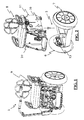
figure 1 is a perspective view of a motorized wheelchair according to the present invention; -
figure 2 is a perspective view of a motorized wheelchair during the step of translationally coupling the main body to the fixing plates; -
figure 3 is a perspective view of a fixing plate and the supporting frame during the step of fixing said fixing plate to said supporting frame; -
figure 4 is a detailed view of a fixing plate; -
figure 5 is a simplified perspective view of the wheelchair wherein only a wall of said main body is shown during the translationally coupling to a fixing plate; -
figure 6 is a detailed view of the above mentioned fixing plate and a side wall of the main body during their translationally coupling; -
figure 7 is a detailed view of the above mentioned fixing plate and a side wall of the main body during the step of blocking the translation between said main body and said at least one fixing plate by said means for blocking the translation; -
figure 8 is a perspective detailed view of one of the abutment profiles present in the side walls of the main body. - Referring in particular to such figures, a motorized wheelchair for the transportation of a seating person has been denoted with
numeral 1. - Such a
wheelchair 1 comprises a supportingframe 2 provided with twoside portions 3, 4 (herein not clearly visible) each having a plurality of threadedholes 5 present on theinner side 3a, 4a of each one of said side portions. In figures only theside portion 3 can be seen, however the side portion 4, being opposite to the other mentionedside portion 3, is the same as theside portion 3 and symmetrical with respect to a longitudinal axis of thewheelchair 1. In practice, the supportingframe 2 takes a U-shape. Furthermore, thewheelchair 1 comprises a couple of wheels 6, 7 each one disposed on the outer side 3b, 4b (not visible in figures) of said twoside portions 3 and 4, a main body 8, provided with aseat 9 and twoside walls frame 2 between said twoside portions 3 and 4. Again, saidwheelchair 1 comprises, as well, a device 12 (seefigure 7 ) for firmly constraining said main body 8 to said supportingframe 2. - It has to be noted that such a typology of
motorized wheelchair 1 also comprises means (herein not shown) for self-equilibrating the weight thereof in any operating condition, which are also employed in the device for the transportation of people known with the name of SEGWAY®. Such means for self-equilibrating the wheelchair weight are housed inside said supportingframe 2 together with further means too for varying the wheelchair forward movement direction. In this type of wheelchair the forward and/ or backward movement is obtained by means of the front and/ or back unbalancing of the user's body. - It has to be noted, however, that such a wheelchair not provided with such means for self-equilibrating and varying the wheelchair direction still falls within the protection scope of the present invention.
- Advantageously, said constraining
device 12 comprises two fixing plates 13 (in figures only one fixing plate is visible) firmly hanged, respectively, on theinner side 3a and 4a (this latter not visible in the figures) of saidside portions 3 and 4 of said supportingframe 2, at said plurality of threadedholes 5, and means 14 for translationally coupling said main body 8 with saidfixing plates 13. In particular, said translationally coupling means 14 comprise four couples ofguide elements guide elements plate 13 and said main body 8. According to the herein represented embodiment, there are two couples ofguide elements plates 13 and theside walls - In detail, and according to the herein described embodiment, said two
guide elements fixing plate 13 comprises, on its owninner side 13a, twoprojections 20, in such a way that the twothroats 15 of the two couples of above mentioned guide elements are obtained in saidprojections 20. Definitively, therefore, being theprojections 20 two for each one of the twofixing plates 13, fourprojections 20 and fourthroats 15 are present. - According to the shown embodiment, the
fixing plate 13, the twoprojections 20 and the tworespective throats 15 are realized in a single piece. - Furthermore, the
abutment profiles 16 are realized, two by two, in the twoside walls 10 and 11 (visible infigures 6 and 7 ) of said main body 8 by material removal of saidside walls such abutment profiles 16 are obtained inside theside wall single throat 15 is coupled with therespective abutment profile 16, theouter edge 40 of thethroat 15 is coupled by interference with theouter edge 41 of thesingle abutment profile 16. As visible infigure 8 , such anouter edge 41 is obtained by material removal of theside wall 10 in such a way that a perimeter hollow 42 is present running inside and parallel along the perimeter of thesame edge 41 inside which theouter edge 40 of thethroat 15 inserts. - In this way any possible and even minimal further horizontal translation of the main body 8 with respect to the
fixing plate 13 is avoided. - Finally, said constraining
device 12 comprises, as well, means 29 for blocking the translation of said main body 8 with respect to said twofixing plates 13. According to the herein described embodiment, such means for blocking thetranslation 29 comprise two threadedelements 30, each one disposed on the two outer sides 10a (herein not shown) and 10b of the twowalls holes 31 for receiving their own threadedelement 31. Each one of said threadedholes 31 is disposed in theupper face 13b of eachfixing plate 13. In practice, the two threadedelements 31 are disposed outside the main body 8 such that once the translationally coupling between the main body 8 and the supportingframe 2 has occurred, the blocking between main body 8 and supportingframe 2 occurs from the outside of the main body 8 simply screwing the threadedelement 30 on the threadedhole 31. The embodiment illustrated in the attached figures shows, for each side of the main body 8, and therefore, of the supportingframe 2, a vertical threadedelement 30 and a corresponding threadedhole 31 with vertical axis for blocking the vertical translation of the main body 8 with respect to the fixingplate 13. This is due to the fact that the translationally coupling means 14 are disposed vertically for the vertical translationally coupling between main body 8 and fixingplate 13. By the way, an embodiment wherein the coupling means 14 were disposed horizontally, as well as the same blocking means 29, would fall within the protection scope of the present invention. In this latter case the threadedhole 31 could have been realized as well on one of the side faces 13c of each present fixingplate 13. - Finally, according to the invention, a method is provided for assembling a
motorized wheelchair 1 comprising the above discussed characteristics, and in particular awheelchair 1 according to one or more of the claims from 1 to 9. Such a method comprises the step of constraining said main body 8 to said supportingframe 2 between said twoside portions 3 and 4. Advantageously, said step of constraining said main body 8 to said supportingframe 2 comprises the steps of: fixing firmly, on theinner side 3a and 4a of said twoside portions 3 and 4 of said supportingframe 2, said two fixingplates 13, at said plurality of threadedholes 5; and translationally coupling said main body 8 to said two fixingplates 13 by said guide means 14. Advantageously, after said step of translationally coupling said main body 8 with said two fixingplates 13 the further step of blocking the translation between said main body 8 and said two fixingplates 13 by said means for blocking the translation is comprised. - By virtue of such a solution any possible translation between said main body 8 and said fixing
plates 13 can be blocked and, thus, between said main body 8 and said supportingframe 2. In this way not only the connection between the main body 8 and the supportingframe 2 is made highly firm, but also assembling thewheelchair 1 is highly simple. In fact, in this case, alignment steps between main body 8 andside portions 3 and 4 of said supportingframe 2 do not need neither to be provided, nor main body 8 and supportingframe 2 have to be blocked by complicated operations for tightening screws disposed, partly, inside the main body 8 to cross it and thus to screw onto the plurality of holes present on the inner side of the two side portions. - The solution allows to perform the assembling operation from the outside of the main body 8, once the latter is translationally coupled to the two fixing
plates 13.
Claims (11)
- Motorized wheelchair (1) for the transportation of at least one sitting person, comprising a supporting frame (2) provided with two side portions (3, 4) each having a plurality of threaded holes (5) present on the inner side (3a, 4a) of both said side portions, a couple of wheels (6, 7) both disposed on the outer side (3b, 4b) of said two side portions (3, 4), a main body (8) provided with a seat (9) and two side walls (10, 11) connectable to said supporting frame between said two side portions, and a device (12) for constraining firmly said main body to said supporting frame, characterized in that said constraining device comprises at least one fixing plate (13) hangable firmly on the inner side (3a; 4a) of least one of said two side portions of said supporting frame, at said plurality of threaded holes, and means (14) for coupling translationally said main body to said fixing plate, and vice versa.
- Motorized wheelchair according to claim 1, characterized in that said coupling means comprise at least one couple of guide elements (15, 16) reciprocally translatable and, respectively, integral to said at least one plate (13) and said main body (8).
- Motorized wheelchair according to claim 2, characterized in that said at least one couple of guide elements comprises, respectively, at least one throat (15) and at least one abutment profile (16) being shaped in such a way to be translationally coupled inside said at least one throat.
- Motorized wheelchair according to claim 3, characterized in that said at least one throat and said at least one abutment profile have substantially a U-shape.
- Motorized wheelchair according to claim 4, characterized in that said at least one fixing plate comprises, on its inner side (13a), at least one projection (20), said at least one throat (15) being obtained in said at least one projection.
- Motorized wheelchair according to claim 5, characterized in that said at least one plate, said at least one projection and said at least one throat are realized in one piece.
- Motorized wheelchair according to one or more of the claims 2 to 6, characterized in that said at least one abutment profile is made in at least one of said two side walls of said main body by material removal of said at least one side wall.
- Motorized wheelchair according to one or more of the preceding claims, characterized in that said constraining device comprises, as well, means (29) for blocking the translation of said at least one main body with respect to said at least one fixing plate.
- Motorized wheelchair according to claim 8, characterized in that said means for blocking the translation comprise at least one threaded element (30) and at least one threaded hole (31) to receive said at least one threaded element, said at least one threaded element (30) and said at least one corresponding threaded hole (31) being disposed, respectively, on the outer side of at least one of said two side walls and on the upper face (13b), or one of the side faces (13c), of said at least one fixing plate, or vice versa.
- Method for assembling a motorized wheelchair according to one or more of the claims 1 to 9, comprising the step of constraining said at least one main body to said supporting frame between said two side portions, characterized in that said step of constraining said at least one main body to said supporting frame comprises the steps of: fixing firmly, on the inner side of at least one of said two side portions of said supporting frame, said at least one fixing plate, at said plurality of threaded holes, and coupling translationally said main body to said fixing plate by said translationally coupling means.
- Method according to claim 10, characterized by comprising, subsequently, the further step of blocking the translation between said main body and said at least one fixing plate by said means for blocking the translation.
Applications Claiming Priority (1)
| Application Number | Priority Date | Filing Date | Title |
|---|---|---|---|
| IT002309A ITMI20112309A1 (en) | 2011-12-19 | 2011-12-19 | MOTORIZED WHEELCHAIR |
Publications (2)
| Publication Number | Publication Date |
|---|---|
| EP2606866A2 true EP2606866A2 (en) | 2013-06-26 |
| EP2606866A3 EP2606866A3 (en) | 2015-08-12 |
Family
ID=45614922
Family Applications (1)
| Application Number | Title | Priority Date | Filing Date |
|---|---|---|---|
| EP12008408.2A Withdrawn EP2606866A3 (en) | 2011-12-19 | 2012-12-18 | Powered wheelchair |
Country Status (2)
| Country | Link |
|---|---|
| EP (1) | EP2606866A3 (en) |
| IT (1) | ITMI20112309A1 (en) |
Cited By (2)
| Publication number | Priority date | Publication date | Assignee | Title |
|---|---|---|---|---|
| WO2016001451A1 (en) * | 2014-07-04 | 2016-01-07 | Universite De Versailles Saint-Quentin-En-Yvelines | Vehicle including a hinged chair with a stand assist mechanism |
| EP4483856A1 (en) | 2023-06-28 | 2025-01-01 | Genny Factory SA | Electric vehicle for micromobility |
Family Cites Families (7)
| Publication number | Priority date | Publication date | Assignee | Title |
|---|---|---|---|---|
| SE417275B (en) * | 1978-11-16 | 1981-03-09 | Per Gotthold Bergman | INSERTABLE WHEELCHAIR |
| AU1360099A (en) * | 1997-10-06 | 1999-04-27 | Pride Health Care, Inc. | Foldable power wheelchair |
| US20050029855A1 (en) * | 2003-03-31 | 2005-02-10 | Hanson Wayne H. | Dynamic seating system for personal mobility vehicle |
| US7455362B2 (en) * | 2005-07-14 | 2008-11-25 | Kids Up, Inc. | Adjustable motion wheel chair |
| US20070085301A1 (en) * | 2005-10-18 | 2007-04-19 | Watkins Mervyn M | Center-of-gravity tilt-in-space wheelchair |
| EP2123245B1 (en) * | 2008-05-19 | 2011-07-27 | Gregor Horacek | Wheelchair, in particular an active wheelchair, with a connection adapter |
| GB201003757D0 (en) * | 2010-03-05 | 2010-04-21 | Tga Electric Leisure Ltd | Wheelchair drive unit |
-
2011
- 2011-12-19 IT IT002309A patent/ITMI20112309A1/en unknown
-
2012
- 2012-12-18 EP EP12008408.2A patent/EP2606866A3/en not_active Withdrawn
Non-Patent Citations (1)
| Title |
|---|
| None |
Cited By (2)
| Publication number | Priority date | Publication date | Assignee | Title |
|---|---|---|---|---|
| WO2016001451A1 (en) * | 2014-07-04 | 2016-01-07 | Universite De Versailles Saint-Quentin-En-Yvelines | Vehicle including a hinged chair with a stand assist mechanism |
| EP4483856A1 (en) | 2023-06-28 | 2025-01-01 | Genny Factory SA | Electric vehicle for micromobility |
Also Published As
| Publication number | Publication date |
|---|---|
| ITMI20112309A1 (en) | 2013-06-20 |
| EP2606866A3 (en) | 2015-08-12 |
Similar Documents
| Publication | Publication Date | Title |
|---|---|---|
| USD1013861S1 (en) | Patient interface frame assembly | |
| WO2009050732A3 (en) | A wheel chair with commode for a patient that converts in to a bed | |
| WO2013006845A3 (en) | Chair, frame and lifting garment useful for patients | |
| US20170128320A1 (en) | Massage chair | |
| WO2005034826A3 (en) | Wheelchair designs and related enhancements | |
| WO2010111662A3 (en) | Personal support | |
| WO2009092101A3 (en) | Adjustable wheelchair | |
| KR101722118B1 (en) | A wheelchair apparatus for detachable of chair part and wheel part | |
| USD557046S1 (en) | Frame for a chair | |
| WO2008107752A3 (en) | Universal seat for shower and bathtub with adjustable-height | |
| KR200465717Y1 (en) | Wheel chair capable of adjusting angles of leg frame therof | |
| US20160088943A1 (en) | Seat | |
| Dubois | Uniqueness for some Leray–Hopf solutions to the Navier–Stokes equations | |
| WO2005115212B1 (en) | Foldable durable patient aid product such as a commode and method of forming same | |
| EP2305197A1 (en) | Wheelchair for heavy persons | |
| GB201004959D0 (en) | Seating safety device | |
| ITRM20140166U1 (en) | V-SHOCK-ABSORBING SEAT APPLICABLE ON A MANUAL WHEELCHAIR FOR DISABLED WHEN IT IS EQUIPPED WITH AN ELECTRIC RIDER | |
| ITPD20020273A1 (en) | MANUAL DISABLED WHEELCHAIR WITH HEIGHT-ADJUSTABLE SEAT. | |
| EP2606866A3 (en) | Powered wheelchair | |
| EP1502565A2 (en) | Weelchair structure for disabled persons | |
| KR200465896Y1 (en) | Combination structure of folding chair low bench | |
| CN211300986U (en) | Multifunctional walking aid for rehabilitation | |
| CN212124936U (en) | Seat waist support with adjustable depth | |
| KR200471955Y1 (en) | A chair | |
| FR2985661B1 (en) | STOOL THAT ALLOWS ONE PERSON TO SIT AND CLOSE TO A SECOND PERSON WITHOUT NEVER HAVE PHYSICAL CONTACT WITH THE LEGS |
Legal Events
| Date | Code | Title | Description |
|---|---|---|---|
| AK | Designated contracting states |
Kind code of ref document: A2 Designated state(s): AL AT BE BG CH CY CZ DE DK EE ES FI FR GB GR HR HU IE IS IT LI LT LU LV MC MK MT NL NO PL PT RO RS SE SI SK SM TR |
|
| AX | Request for extension of the european patent |
Extension state: BA ME |
|
| PUAI | Public reference made under article 153(3) epc to a published international application that has entered the european phase |
Free format text: ORIGINAL CODE: 0009012 |
|
| RAP1 | Party data changed (applicant data changed or rights of an application transferred) |
Owner name: GENNY MOBILITY SA |
|
| PUAL | Search report despatched |
Free format text: ORIGINAL CODE: 0009013 |
|
| AK | Designated contracting states |
Kind code of ref document: A3 Designated state(s): AL AT BE BG CH CY CZ DE DK EE ES FI FR GB GR HR HU IE IS IT LI LT LU LV MC MK MT NL NO PL PT RO RS SE SI SK SM TR |
|
| AX | Request for extension of the european patent |
Extension state: BA ME |
|
| RIC1 | Information provided on ipc code assigned before grant |
Ipc: A61G 5/04 20130101AFI20150709BHEP Ipc: A61G 5/10 20060101ALI20150709BHEP |
|
| 17P | Request for examination filed |
Effective date: 20160211 |
|
| RBV | Designated contracting states (corrected) |
Designated state(s): AL AT BE BG CH CY CZ DE DK EE ES FI FR GB GR HR HU IE IS IT LI LT LU LV MC MK MT NL NO PL PT RO RS SE SI SK SM TR |
|
| 17Q | First examination report despatched |
Effective date: 20190327 |
|
| STAA | Information on the status of an ep patent application or granted ep patent |
Free format text: STATUS: THE APPLICATION IS DEEMED TO BE WITHDRAWN |
|
| 18D | Application deemed to be withdrawn |
Effective date: 20190807 |