EP2606852A1 - Endoluminal prosthesis comprising a valve replacement and at least one fenestration - Google Patents
Endoluminal prosthesis comprising a valve replacement and at least one fenestration Download PDFInfo
- Publication number
- EP2606852A1 EP2606852A1 EP20120198788 EP12198788A EP2606852A1 EP 2606852 A1 EP2606852 A1 EP 2606852A1 EP 20120198788 EP20120198788 EP 20120198788 EP 12198788 A EP12198788 A EP 12198788A EP 2606852 A1 EP2606852 A1 EP 2606852A1
- Authority
- EP
- European Patent Office
- Prior art keywords
- graft
- prosthesis
- perimeter
- fenestration
- band
- Prior art date
- Legal status (The legal status is an assumption and is not a legal conclusion. Google has not performed a legal analysis and makes no representation as to the accuracy of the status listed.)
- Granted
Links
Images




Classifications
-
- A—HUMAN NECESSITIES
- A61—MEDICAL OR VETERINARY SCIENCE; HYGIENE
- A61F—FILTERS IMPLANTABLE INTO BLOOD VESSELS; PROSTHESES; DEVICES PROVIDING PATENCY TO, OR PREVENTING COLLAPSING OF, TUBULAR STRUCTURES OF THE BODY, e.g. STENTS; ORTHOPAEDIC, NURSING OR CONTRACEPTIVE DEVICES; FOMENTATION; TREATMENT OR PROTECTION OF EYES OR EARS; BANDAGES, DRESSINGS OR ABSORBENT PADS; FIRST-AID KITS
- A61F2/00—Filters implantable into blood vessels; Prostheses, i.e. artificial substitutes or replacements for parts of the body; Appliances for connecting them with the body; Devices providing patency to, or preventing collapsing of, tubular structures of the body, e.g. stents
- A61F2/02—Prostheses implantable into the body
- A61F2/24—Heart valves ; Vascular valves, e.g. venous valves; Heart implants, e.g. passive devices for improving the function of the native valve or the heart muscle; Transmyocardial revascularisation [TMR] devices; Valves implantable in the body
- A61F2/2412—Heart valves ; Vascular valves, e.g. venous valves; Heart implants, e.g. passive devices for improving the function of the native valve or the heart muscle; Transmyocardial revascularisation [TMR] devices; Valves implantable in the body with soft flexible valve members, e.g. tissue valves shaped like natural valves
-
- A—HUMAN NECESSITIES
- A61—MEDICAL OR VETERINARY SCIENCE; HYGIENE
- A61F—FILTERS IMPLANTABLE INTO BLOOD VESSELS; PROSTHESES; DEVICES PROVIDING PATENCY TO, OR PREVENTING COLLAPSING OF, TUBULAR STRUCTURES OF THE BODY, e.g. STENTS; ORTHOPAEDIC, NURSING OR CONTRACEPTIVE DEVICES; FOMENTATION; TREATMENT OR PROTECTION OF EYES OR EARS; BANDAGES, DRESSINGS OR ABSORBENT PADS; FIRST-AID KITS
- A61F2/00—Filters implantable into blood vessels; Prostheses, i.e. artificial substitutes or replacements for parts of the body; Appliances for connecting them with the body; Devices providing patency to, or preventing collapsing of, tubular structures of the body, e.g. stents
- A61F2/95—Instruments specially adapted for placement or removal of stents or stent-grafts
- A61F2/962—Instruments specially adapted for placement or removal of stents or stent-grafts having an outer sleeve
-
- A—HUMAN NECESSITIES
- A61—MEDICAL OR VETERINARY SCIENCE; HYGIENE
- A61F—FILTERS IMPLANTABLE INTO BLOOD VESSELS; PROSTHESES; DEVICES PROVIDING PATENCY TO, OR PREVENTING COLLAPSING OF, TUBULAR STRUCTURES OF THE BODY, e.g. STENTS; ORTHOPAEDIC, NURSING OR CONTRACEPTIVE DEVICES; FOMENTATION; TREATMENT OR PROTECTION OF EYES OR EARS; BANDAGES, DRESSINGS OR ABSORBENT PADS; FIRST-AID KITS
- A61F2/00—Filters implantable into blood vessels; Prostheses, i.e. artificial substitutes or replacements for parts of the body; Appliances for connecting them with the body; Devices providing patency to, or preventing collapsing of, tubular structures of the body, e.g. stents
- A61F2/02—Prostheses implantable into the body
- A61F2/04—Hollow or tubular parts of organs, e.g. bladders, tracheae, bronchi or bile ducts
- A61F2/06—Blood vessels
- A61F2/07—Stent-grafts
-
- A—HUMAN NECESSITIES
- A61—MEDICAL OR VETERINARY SCIENCE; HYGIENE
- A61F—FILTERS IMPLANTABLE INTO BLOOD VESSELS; PROSTHESES; DEVICES PROVIDING PATENCY TO, OR PREVENTING COLLAPSING OF, TUBULAR STRUCTURES OF THE BODY, e.g. STENTS; ORTHOPAEDIC, NURSING OR CONTRACEPTIVE DEVICES; FOMENTATION; TREATMENT OR PROTECTION OF EYES OR EARS; BANDAGES, DRESSINGS OR ABSORBENT PADS; FIRST-AID KITS
- A61F2/00—Filters implantable into blood vessels; Prostheses, i.e. artificial substitutes or replacements for parts of the body; Appliances for connecting them with the body; Devices providing patency to, or preventing collapsing of, tubular structures of the body, e.g. stents
- A61F2/02—Prostheses implantable into the body
- A61F2/24—Heart valves ; Vascular valves, e.g. venous valves; Heart implants, e.g. passive devices for improving the function of the native valve or the heart muscle; Transmyocardial revascularisation [TMR] devices; Valves implantable in the body
- A61F2/2412—Heart valves ; Vascular valves, e.g. venous valves; Heart implants, e.g. passive devices for improving the function of the native valve or the heart muscle; Transmyocardial revascularisation [TMR] devices; Valves implantable in the body with soft flexible valve members, e.g. tissue valves shaped like natural valves
- A61F2/2418—Scaffolds therefor, e.g. support stents
-
- A—HUMAN NECESSITIES
- A61—MEDICAL OR VETERINARY SCIENCE; HYGIENE
- A61F—FILTERS IMPLANTABLE INTO BLOOD VESSELS; PROSTHESES; DEVICES PROVIDING PATENCY TO, OR PREVENTING COLLAPSING OF, TUBULAR STRUCTURES OF THE BODY, e.g. STENTS; ORTHOPAEDIC, NURSING OR CONTRACEPTIVE DEVICES; FOMENTATION; TREATMENT OR PROTECTION OF EYES OR EARS; BANDAGES, DRESSINGS OR ABSORBENT PADS; FIRST-AID KITS
- A61F2/00—Filters implantable into blood vessels; Prostheses, i.e. artificial substitutes or replacements for parts of the body; Appliances for connecting them with the body; Devices providing patency to, or preventing collapsing of, tubular structures of the body, e.g. stents
- A61F2/82—Devices providing patency to, or preventing collapsing of, tubular structures of the body, e.g. stents
- A61F2/86—Stents in a form characterised by the wire-like elements; Stents in the form characterised by a net-like or mesh-like structure
- A61F2/89—Stents in a form characterised by the wire-like elements; Stents in the form characterised by a net-like or mesh-like structure the wire-like elements comprising two or more adjacent rings flexibly connected by separate members
-
- A—HUMAN NECESSITIES
- A61—MEDICAL OR VETERINARY SCIENCE; HYGIENE
- A61F—FILTERS IMPLANTABLE INTO BLOOD VESSELS; PROSTHESES; DEVICES PROVIDING PATENCY TO, OR PREVENTING COLLAPSING OF, TUBULAR STRUCTURES OF THE BODY, e.g. STENTS; ORTHOPAEDIC, NURSING OR CONTRACEPTIVE DEVICES; FOMENTATION; TREATMENT OR PROTECTION OF EYES OR EARS; BANDAGES, DRESSINGS OR ABSORBENT PADS; FIRST-AID KITS
- A61F2/00—Filters implantable into blood vessels; Prostheses, i.e. artificial substitutes or replacements for parts of the body; Appliances for connecting them with the body; Devices providing patency to, or preventing collapsing of, tubular structures of the body, e.g. stents
- A61F2/95—Instruments specially adapted for placement or removal of stents or stent-grafts
- A61F2/954—Instruments specially adapted for placement or removal of stents or stent-grafts for placing stents or stent-grafts in a bifurcation
-
- A—HUMAN NECESSITIES
- A61—MEDICAL OR VETERINARY SCIENCE; HYGIENE
- A61F—FILTERS IMPLANTABLE INTO BLOOD VESSELS; PROSTHESES; DEVICES PROVIDING PATENCY TO, OR PREVENTING COLLAPSING OF, TUBULAR STRUCTURES OF THE BODY, e.g. STENTS; ORTHOPAEDIC, NURSING OR CONTRACEPTIVE DEVICES; FOMENTATION; TREATMENT OR PROTECTION OF EYES OR EARS; BANDAGES, DRESSINGS OR ABSORBENT PADS; FIRST-AID KITS
- A61F2/00—Filters implantable into blood vessels; Prostheses, i.e. artificial substitutes or replacements for parts of the body; Appliances for connecting them with the body; Devices providing patency to, or preventing collapsing of, tubular structures of the body, e.g. stents
- A61F2/02—Prostheses implantable into the body
- A61F2/04—Hollow or tubular parts of organs, e.g. bladders, tracheae, bronchi or bile ducts
- A61F2/06—Blood vessels
- A61F2002/061—Blood vessels provided with means for allowing access to secondary lumens
-
- A—HUMAN NECESSITIES
- A61—MEDICAL OR VETERINARY SCIENCE; HYGIENE
- A61F—FILTERS IMPLANTABLE INTO BLOOD VESSELS; PROSTHESES; DEVICES PROVIDING PATENCY TO, OR PREVENTING COLLAPSING OF, TUBULAR STRUCTURES OF THE BODY, e.g. STENTS; ORTHOPAEDIC, NURSING OR CONTRACEPTIVE DEVICES; FOMENTATION; TREATMENT OR PROTECTION OF EYES OR EARS; BANDAGES, DRESSINGS OR ABSORBENT PADS; FIRST-AID KITS
- A61F2/00—Filters implantable into blood vessels; Prostheses, i.e. artificial substitutes or replacements for parts of the body; Appliances for connecting them with the body; Devices providing patency to, or preventing collapsing of, tubular structures of the body, e.g. stents
- A61F2/02—Prostheses implantable into the body
- A61F2/04—Hollow or tubular parts of organs, e.g. bladders, tracheae, bronchi or bile ducts
- A61F2/06—Blood vessels
- A61F2/07—Stent-grafts
- A61F2002/075—Stent-grafts the stent being loosely attached to the graft material, e.g. by stitching
-
- A—HUMAN NECESSITIES
- A61—MEDICAL OR VETERINARY SCIENCE; HYGIENE
- A61F—FILTERS IMPLANTABLE INTO BLOOD VESSELS; PROSTHESES; DEVICES PROVIDING PATENCY TO, OR PREVENTING COLLAPSING OF, TUBULAR STRUCTURES OF THE BODY, e.g. STENTS; ORTHOPAEDIC, NURSING OR CONTRACEPTIVE DEVICES; FOMENTATION; TREATMENT OR PROTECTION OF EYES OR EARS; BANDAGES, DRESSINGS OR ABSORBENT PADS; FIRST-AID KITS
- A61F2/00—Filters implantable into blood vessels; Prostheses, i.e. artificial substitutes or replacements for parts of the body; Appliances for connecting them with the body; Devices providing patency to, or preventing collapsing of, tubular structures of the body, e.g. stents
- A61F2/95—Instruments specially adapted for placement or removal of stents or stent-grafts
- A61F2/962—Instruments specially adapted for placement or removal of stents or stent-grafts having an outer sleeve
- A61F2/966—Instruments specially adapted for placement or removal of stents or stent-grafts having an outer sleeve with relative longitudinal movement between outer sleeve and prosthesis, e.g. using a push rod
- A61F2002/9665—Instruments specially adapted for placement or removal of stents or stent-grafts having an outer sleeve with relative longitudinal movement between outer sleeve and prosthesis, e.g. using a push rod with additional retaining means
-
- A—HUMAN NECESSITIES
- A61—MEDICAL OR VETERINARY SCIENCE; HYGIENE
- A61F—FILTERS IMPLANTABLE INTO BLOOD VESSELS; PROSTHESES; DEVICES PROVIDING PATENCY TO, OR PREVENTING COLLAPSING OF, TUBULAR STRUCTURES OF THE BODY, e.g. STENTS; ORTHOPAEDIC, NURSING OR CONTRACEPTIVE DEVICES; FOMENTATION; TREATMENT OR PROTECTION OF EYES OR EARS; BANDAGES, DRESSINGS OR ABSORBENT PADS; FIRST-AID KITS
- A61F2210/00—Particular material properties of prostheses classified in groups A61F2/00 - A61F2/26 or A61F2/82 or A61F9/00 or A61F11/00 or subgroups thereof
- A61F2210/0076—Particular material properties of prostheses classified in groups A61F2/00 - A61F2/26 or A61F2/82 or A61F9/00 or A61F11/00 or subgroups thereof multilayered, e.g. laminated structures
-
- A—HUMAN NECESSITIES
- A61—MEDICAL OR VETERINARY SCIENCE; HYGIENE
- A61F—FILTERS IMPLANTABLE INTO BLOOD VESSELS; PROSTHESES; DEVICES PROVIDING PATENCY TO, OR PREVENTING COLLAPSING OF, TUBULAR STRUCTURES OF THE BODY, e.g. STENTS; ORTHOPAEDIC, NURSING OR CONTRACEPTIVE DEVICES; FOMENTATION; TREATMENT OR PROTECTION OF EYES OR EARS; BANDAGES, DRESSINGS OR ABSORBENT PADS; FIRST-AID KITS
- A61F2220/00—Fixations or connections for prostheses classified in groups A61F2/00 - A61F2/26 or A61F2/82 or A61F9/00 or A61F11/00 or subgroups thereof
- A61F2220/0008—Fixation appliances for connecting prostheses to the body
- A61F2220/0016—Fixation appliances for connecting prostheses to the body with sharp anchoring protrusions, e.g. barbs, pins, spikes
-
- A—HUMAN NECESSITIES
- A61—MEDICAL OR VETERINARY SCIENCE; HYGIENE
- A61F—FILTERS IMPLANTABLE INTO BLOOD VESSELS; PROSTHESES; DEVICES PROVIDING PATENCY TO, OR PREVENTING COLLAPSING OF, TUBULAR STRUCTURES OF THE BODY, e.g. STENTS; ORTHOPAEDIC, NURSING OR CONTRACEPTIVE DEVICES; FOMENTATION; TREATMENT OR PROTECTION OF EYES OR EARS; BANDAGES, DRESSINGS OR ABSORBENT PADS; FIRST-AID KITS
- A61F2220/00—Fixations or connections for prostheses classified in groups A61F2/00 - A61F2/26 or A61F2/82 or A61F9/00 or A61F11/00 or subgroups thereof
- A61F2220/0025—Connections or couplings between prosthetic parts, e.g. between modular parts; Connecting elements
- A61F2220/005—Connections or couplings between prosthetic parts, e.g. between modular parts; Connecting elements using adhesives
-
- A—HUMAN NECESSITIES
- A61—MEDICAL OR VETERINARY SCIENCE; HYGIENE
- A61F—FILTERS IMPLANTABLE INTO BLOOD VESSELS; PROSTHESES; DEVICES PROVIDING PATENCY TO, OR PREVENTING COLLAPSING OF, TUBULAR STRUCTURES OF THE BODY, e.g. STENTS; ORTHOPAEDIC, NURSING OR CONTRACEPTIVE DEVICES; FOMENTATION; TREATMENT OR PROTECTION OF EYES OR EARS; BANDAGES, DRESSINGS OR ABSORBENT PADS; FIRST-AID KITS
- A61F2220/00—Fixations or connections for prostheses classified in groups A61F2/00 - A61F2/26 or A61F2/82 or A61F9/00 or A61F11/00 or subgroups thereof
- A61F2220/0025—Connections or couplings between prosthetic parts, e.g. between modular parts; Connecting elements
- A61F2220/0075—Connections or couplings between prosthetic parts, e.g. between modular parts; Connecting elements sutured, ligatured or stitched, retained or tied with a rope, string, thread, wire or cable
-
- A—HUMAN NECESSITIES
- A61—MEDICAL OR VETERINARY SCIENCE; HYGIENE
- A61F—FILTERS IMPLANTABLE INTO BLOOD VESSELS; PROSTHESES; DEVICES PROVIDING PATENCY TO, OR PREVENTING COLLAPSING OF, TUBULAR STRUCTURES OF THE BODY, e.g. STENTS; ORTHOPAEDIC, NURSING OR CONTRACEPTIVE DEVICES; FOMENTATION; TREATMENT OR PROTECTION OF EYES OR EARS; BANDAGES, DRESSINGS OR ABSORBENT PADS; FIRST-AID KITS
- A61F2230/00—Geometry of prostheses classified in groups A61F2/00 - A61F2/26 or A61F2/82 or A61F9/00 or A61F11/00 or subgroups thereof
- A61F2230/0002—Two-dimensional shapes, e.g. cross-sections
- A61F2230/0028—Shapes in the form of latin or greek characters
- A61F2230/0054—V-shaped
-
- A—HUMAN NECESSITIES
- A61—MEDICAL OR VETERINARY SCIENCE; HYGIENE
- A61F—FILTERS IMPLANTABLE INTO BLOOD VESSELS; PROSTHESES; DEVICES PROVIDING PATENCY TO, OR PREVENTING COLLAPSING OF, TUBULAR STRUCTURES OF THE BODY, e.g. STENTS; ORTHOPAEDIC, NURSING OR CONTRACEPTIVE DEVICES; FOMENTATION; TREATMENT OR PROTECTION OF EYES OR EARS; BANDAGES, DRESSINGS OR ABSORBENT PADS; FIRST-AID KITS
- A61F2230/00—Geometry of prostheses classified in groups A61F2/00 - A61F2/26 or A61F2/82 or A61F9/00 or A61F11/00 or subgroups thereof
- A61F2230/0063—Three-dimensional shapes
- A61F2230/0067—Three-dimensional shapes conical
Definitions
- the functional vessels of human and animal bodies such as blood vessels and ducts, occasionally weaken or even rupture.
- the aortic wall can weaken, resulting in an aneurysm, or it may develop a tear in one of the layers of the aortic wall resulting in an aortic dissection.
- Endoluminal prostheses may be of a unitary construction or may be comprised of multiple prosthetic modules. They also may be a single tubular device or a bifurcated branching device depending on the desired application.
- the damaged or defected portion of the vasculature may include a branch vessel branching from the main vessel.
- a branch vessel branching from the main vessel For example, in the case of the abdominal aorta, there are at least three major branch vessels, including the celiac, mesenteric, and renal arteries, as well as other others, leading to various other body organs.
- the damaged portion of the vessel includes one or more of these branch vessels, some accommodation must be made to ensure that the prosthesis does not block or hinder blood flow through the branch vessel.
- An endoluminal prosthesis comprises a graft having a tubular body comprising proximal and distal ends, and a valve replacement disposed between the proximal and distal ends of the graft.
- At least one stent is coupled to the graft and has a contracted delivery state and an expanded state for maintaining patency within a portion of the graft.
- At least one fenestration is disposed in a sidewall of the graft at a location distal to the valve replacement.
- the at least one fenestration is pivotable in any direction away from an axis perpendicular to a longitudinal axis of the prosthesis.
- the band of material has a first diameter substantially the same as the first perimeter diameter and a second diameter substantially the same as the diameter of the second perimeter. The diameter of the band of material decreases in a direction away from the surface of the graft from the second perimeter to the first perimeter.
- the band of material has a concave or convex orientation relative to the surface of the graft.
- the band of material may be configured to independently move between an interior surface of the graft and an exterior surface of the graft.
- first and second fenestrations may be disposed in the graft at locations between about 90 and about 270 degrees apart.
- a first branch vessel prosthesis may extend between the first fenestration and a right coronary artery in a deployed state, and a second branch vessel prosthesis may extend between the second fenestration and a left coronary artery in the deployed state.
- the valve replacement may comprise an artificial valve having a tricuspid shape.
- the valve replacement may be located at the proximal end of the graft, and one or more barbs extend radially outward from the proximal end of the graft.
- the present disclosure relates to an endoluminal prosthesis, such as a stent graft that includes one or more fenestrations to accommodate endovascular disease, such as an aneurysm in cases where one or more side branches is involved, and a side branch prosthesis is deployed within the fenestration to permit fluid flow from the endoluminal prosthesis into the branch vessel.
- the prosthesis includes fenestrations that pivot as needed to accommodate the dynamic geometry of the aortic branches.
- one or more pivotable fenestrations provided on a prosthesis lie outside the surface plane of the body of the prosthesis and will allow a branch vessel stent, graft or stent-graft that has been placed in the fenestration to pivot into a variety of orientations required to meet and seal the branch vessel device in the branch vessel.
- the orientation of the fenestrations may dynamically change over time as needed by changing anatomy.
- distal means a location or direction that is, or a portion of a device that when implanted is further downstream in the direction of or with respect to blood flow.
- proximal means a location or direction that is, or a portion of a device that when implanted is further upstream in the direction of or with respect to blood flow.
- fenestration means an opening provided through a surface of a prosthesis from the interior of the prosthesis to the exterior of the prostheses and may have a variety of geometries, including circular, semi-circular, oval, oblong, as well as other geometries.
- biocompatible refers to a material that is substantially non-toxic in the in vivo environment of its intended use, and that is not substantially rejected by the patient's physiological system (i.e., is non-antigenic).
- biocompatible materials from which textile graft material can be formed include, without limitation, polyesters, such as polyethylene terephthalate; fluorinated polymers, such as polytetrafluoroethylene (PTFE) and fibers of expanded PTFE, and polyurethanes.
- PTFE polytetrafluoroethylene
- materials that are not inherently biocompatible may be subjected to surface modifications in order to render the materials biocompatible.
- Examples of surface modifications include graft polymerization of biocompatible polymers on the materials surface, coating of the surface with a crosslinked biocompatible polymer, chemical modification with biocompatible functional groups, and immobilization of a compatibilizing agent such as heparin or other biocompatible substances.
- a compatibilizing agent such as heparin or other biocompatible substances.
- any fibrous material having sufficient strength to survive in the in vivo environment may be used to form a textile graft, provided the final textile is biocompatible.
- Fibers suitable for making textile grafts include polyethylene, polypropylene, polyaramids, polyacrylonitrile, nylon, and cellulose, in addition to the polyesters, fluorinated polymers, and polyurethanes as listed above.
- bioremodelable materials may also be used singly or in combination with the aforementioned polymer materials.
- the textile may be made of one or more polymers that do not require treatment or modification to be biocompatible.
- the graft may be constructed from woven multifilament polyester, for example and without limitation, DacronTM, produced by DuPONT. DacronTM is known to be sufficiently biologically inert, non-biodegradable, and durable to permit safe insertion inside the human body.
- prosthesis means any device for insertion or implantation into or replacement for a body part or function of that body part. It may also mean a device that enhances or adds functionality to a physiological system.
- prosthesis may include, for example and without limitation, a stent, stent-graft, filter, valve, balloon, embolization coil, and the like.
- tubular refers to the general shape of an endoluminal device which allows the module to carry fluid along a distance or fit within a tubular structure such as an artery.
- Tubular prosthetic devices include single, branched, and bifurcated devices.
- Tubular may refer to any shape including, but not limited to, tapered, cylindrical, curvilinear, or any combination thereof.
- a tubular device may have a cross-sectional shape that is, circular, substantially circular or the like. However, it should be understood that the cross-sectional shape is not limited thereto, and other shapes, such as, for example, hexagonal, pentagonal, octagonal, or the like are contemplated.
- endoluminal refers to or describes objects that can be placed inside a lumen or a body passageway in a human or animal body.
- a lumen or a body passageway can be an existing lumen or a lumen created by surgical intervention.
- the terms “lumen” or “body passageway” are intended to have a broad meaning and encompasses any duct (e.g., natural or iatrogenic) within the human body and can include a member selected from the group comprising: blood vessels, respiratory ducts, gastrointestinal ducts, and the like.
- Endoluminal device or “endoluminal prosthesis” thus describes devices that can be placed inside one of these lumens.
- graft or "graft material” describes an object, device, or structure that is joined to or that is capable of being joined to or implanted in or against a body part to enhance, repair, or replace a portion or a function of that body part.
- a graft by itself or with the addition of other elements, such as structural components, may comprise an endoluminal prosthesis.
- the graft may be comprised of a single material, a blend of materials, a weave, a laminate, or a composite of two or more materials.
- the graft may be constructed from natural or organic materials, for example and without limitation, a biological scaffold or bioremodelable material, such as small intestine submucosa ("SIS”), which is commercially available by Cook Biotech, West Lafayette, IN.
- SIS small intestine submucosa
- the graft may also be constructed from a synthetic, for example and without limitation, a polymer.
- the graft may be formed from a single layer or multiple layers of material. In embodiments employing a plurality of layers of material, the layers may remain separate, or may be attached to each other through a secondary process such as sintering, curing, adhesives, and sutures or the like.
- stent means any device or structure that adds rigidity, expansion force or support to a prosthesis.
- a stent is used to obtain and maintain the patency of the body passageway while maintaining the integrity-of the passageway.
- the stent may be used to form a seal.
- the stent may be located on the exterior of the device, the interior of the device, or both.
- a stent may be self-expanding, balloon-expandable or may have characteristics of both.
- the stents 16 may be comprised of a metallic material selected from stainless steel, silver, platinum, palladium, gold, titanium, tantalum, iridium, tungsten, cobalt, chromium, cobalt-chromium alloy 1058, cobalt-based 35N alloy, nickel-based alloy 625, a molybdenum alloy, a molybdenum alloy including about 0.4% to about 0.8% of lanthanum oxide (Li 2 O 3 ), and a nickel-titanium alloy, such as nitinol, or other suitable materials as known in the art.
- the stents may be made of a wire, or may be laser or cannula cut, or manufactured by other known methods.
- fused refers to a length of a continuous thread or strand of one or more filaments or fibers, with or without twist, suitable for weaving, knitting or otherwise intertwining to form a textile fabric.
- branch vessel refers to a vessel that branches off from a main vessel.
- examples are the celiac and renal arteries which are branch vessels to the aorta (i.e., the main vessel in this context).
- the hypogastric artery is a branch vessel to the common iliac, which is a main vessel in this context.
- Longitudinally refers to a direction, position or length substantially parallel with a longitudinal axis of a reference, and is the length-wise component of the helical orientation.
- Circumferentially refers to a direction, position, or length that encircles a longitudinal axis of reference.
- the term “circumferential” is not restricted to a full 360° circumferential turn or to a constant radius.
- patient refers to any animal, especially humans.
- Figures 1-8 show a fenestrated prosthesis 10, here a stent graft, having a tubular body and comprising a biocompatible material, having one or more fenestrations 12 pivotable in any direction away from an axis perpendicular to a longitudinal axis of the prosthesis.
- the pivotable fenestrations 12 have a diameter extending from a sidewall of the graft.
- the pivotable fenestrations 12 include a first, inner perimeter 26 surrounding the fenestration 12 having a diameter, a band 28 of flexible material attached to and surrounding the first perimeter 26, and a second, outer perimeter 30 attached to and surrounding the band 28 of flexible material.
- the band 28 of material has a first diameter that is substantially the same as the diameter of the first perimeter 26, and a second diameter substantially the same as the second perimeter 30.
- the diameter of the band of material decreases in a direction away from the surface 20 of the graft 14 from the second perimeter to the first perimeter.
- the band of flexible material may include a flexible frame 48.
- the fenestrated prosthesis 10 is intended for placement in the abdominal aorta and to accommodate vessels that branch from the aorta, for example, the renal arteries, and into which a branch vessel prosthesis may be placed.
- the fenestrated prosthesis 10 is not limited for use in the abdominal aorta but may be used in other vessels of the body from which other vessels branch, such as the ascending thoracic aorta, the descending thoracic aorta, as well as other body vessels.
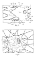
- FIG 1 shows a perspective view of a prosthesis 10 that is a stent graft.
- the prosthesis 10 includes graft material 14 associated with one or more stents 16.
- the prosthesis 10 has a proximal end 22, a distal end 24, and a lumen 18 extending through the prosthesis 10 to permit passage of blood flow from the proximal end 22 to the distal end 24.
- the stents 16 may be placed on the external surface 20 and/or internal surface 21 of the graft material 14.
- the prosthesis 10, such as that shown in Figure 1 has external body stents 16a, 16b, and 16c, and at least one internal stent 16d.
- the internal stent 16d may be a sealing stent and placed at or near the proximal end 22 of the prosthesis 10 to seal the prosthesis 10 at the proximal end 22 to the walls of a blood vessel into which it has been placed. Additionally, or alternatively, depending on the location of the place of the prosthesis 10 or a particular need, a sealing stent 16d may be placed at either or both the proximal and distal ends 22, 24 of prosthesis 10.
- the prosthesis 10 also may include an attachment mechanism, for example, an attachment stent 42, at either or both ends of the prosthesis 10, to further secure the prosthesis 10 within the body vessel and prevent migration of the prosthesis 10.
- the prosthesis 10 has several openings or fenestrations that extend from the internal surface 21 to the external surface 20 of the graft material 14.
- the prosthesis 10 of Figure 1 has two pivotable fenestrations 12, at least one non-pivotable fenestration 38, and a scallop 40.
- the scallop 40 is placed at the proximal end of the prosthesis 10.
- FIGS. 1-8 show various aspects and views of the prosthesis 10 having pivotable fenestrations 12.
- Pivotable fenestrations 12 have an inner perimeter 26 surrounding the fenestration 12, a band 28 surrounding the inner perimeter 26, and an outer perimeter 30 surrounding the band 28.
- the outer perimeter 30 diameter is greater than the band 28 diameter and the inner perimeter diameter 26.
- the inner perimeter 26, the band 28 and the outer perimeter 30 would be substantially concentric with one another if they were in the same plane, for example the surface plane of the graft.
- the inner perimeter 26, the band 28 and the outer perimeter 30 may form a hemispherical shape, resembling a dome, or a frustoconical cone extending from the surface of the graft material 14.
- the fenestration 12 is provided at the peak or top of the hemispherical shape or extension.
- the band 28 may comprise a tapered, flexible tube extending from the outer perimeter 30 and the inner diameter 26.
- Stents 16 for example those shown in the Figures may be, for example zig zag stents, also known has Z-stents, that comprise a series of struts 32, 34 connected by apices 36, although the type of stent used is not so limited. When Z-stents are used, a portion of the outer perimeter 30 of one or more of the fenestrations 12 may lie between adjacent struts 32, 34 of one of the stents 16.
- the stents 16 may be either self-expanding or balloon expandable. Preferably, they are self-expanding. However, a combination of self-expanding and balloon expandable stents also may be contemplated.
- the stents 16 include struts 32, 34 that are spaced apart from each other.
- the strut spacing is measured from bend-to-bend (or apex to apex 36). Stent amplitude, spacing and stagger are preferably optimized for each prosthesis design.
- the apices or bends 36 of the struts 32, 34 may be staggered for minimal contact with each other.
- the stents 16a, 16b, 16c are positioned adjacent each other and the apices 36 of each row are in circumferential alignment with the bends of longitudinally adjacent rows.
- every bend 36 of each row may be in substantial circumferential alignment with the bends 36 of longitudinally adjacent rows.
- the pivotable fenestrations 12 may be located within the lumen 18 of the prosthesis 10 or extending from the exterior of the prosthesis 10. In the first aspect, the pivotable fenestrations 12 may be said to be concave, relative to the external surface 20 of the graft material 14. In the second aspect, the pivotable fenestrations 12 may be said to be convex, relative to the external surface 20 of the graft material 14.
- Figure 1 shows the pivotable fenestrations 12 located internal to the prosthesis 10 that is, they lie within the lumen 18 of the prosthesis 10. In the particular aspect shown in Figure 1 , the pivotable fenestrations 12 reside substantially on one side of the prosthesis 10 and are adjacent to one another.
- the pivotable fenestrations 12 are positioned to align with, for example, the renal arteries.
- the one or more pivotable fenestrations 12 may be positioned to align with other branch arteries throughout a diseased vasculature. Additional fenestrations and scallops as disclosed here may also be included.
- FIG 2 which is a partial internal view of the prosthesis 10 of Figure 1 , shows a view of the prosthesis 10 looking into the lumen 18 of the prosthesis 10 from the proximal end 22.
- pivotable fenestrations 12 extend or protrude into the lumen 18.
- Pivotable fenestrations 12 have an inner perimeter 26, a band 28, and an outer perimeter 30.
- the outer perimeter 30 lies substantially flush (in the same plane) of the graft material 14, and the band 28 and the outer perimeter 30 form a hemispherical shape, such as a dome or frustoconical cone extending into the lumen 18.
- both the first and outer perimeters 26, 30 are shown as substantially circular, they may be oval, oblong or some other desired geometric shape.
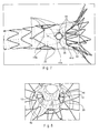
- Figures 3 and 4 show an aspect of a prosthesis 10 having externally extending pivotable fenestrations 12.
- Figure 3 shows a partial view of a prosthesis 10 having two externally extending pivotable fenestrations 12 extending form opposite sides of the prosthesis 10.
- the fenestrations 12 have an inner perimeter 26 surrounding the fenestration, a band 28 of material surrounding the inner perimeter 26, and an outer perimeter 30 surrounding the band 28 of material.
- Figure 4 which is a partial internal view of the prosthesis 10 of Figure 3 , shows a view of the prosthesis 10 of Figure 3 , looking into the lumen 18 of the prosthesis 10 from the proximal end 22.
- pivotable fenestrations 12 extent or protrude away from the external surface 20 of the graft material 14.
- the outer perimeter 30 lies substantially flush (in the same plane) of the graft material 14, and the band 28 and the outer perimeter 30 form a hemispherical shape, such as a dome, or frustoconical cone extending into the lumen 18.
- Figures 5 and 6 show further aspects of a fenestrated prosthesis 10 having at least one pivotable fenestration 12.
- Figure 5 shows a prosthesis 10 that is a stent graft.
- the prosthesis includes that has a proximal end 22, a distal end 24, a graft material 14 associated with a series of external stents 16.
- the prosthesis 10 further has an internal sealing stent 16d, and attachment stent 42, and a pivotable fenestration 12.
- Figure 6 shows a partial close up view of the fenestration of Figure 5 .
- the pivotable fenestration 12 shown is an external fenestration 12 and has an inner perimeter 26 surrounding the fenestration 12, a band 28 of material surrounding the inner perimeter 26, and an outer perimeter 30 surrounding the band 26. As shown, a portion of the outer perimeter 30 lies between struts 32, 34 of the proximal most stent 16.
- the prosthesis 10 includes a non-pivoting fenestration 28 and a scallop 40 at the proximal end 22.
- imageable markers 35 which may be viewed during and after placement of the prosthesis 10 may be placed at various locations on the prosthesis 10 to identify certain aspects of the prosthesis and their location during the implantation procedure and facilitate correct placement of the fenestrations 12, 38, scallop 40, the ends of the prosthesis and the like.
- markers 35 may be placed about the circumference of the outer perimeter 30.
- the markers 35 may be, for example, sewn or sutured to the graft material 14, as shown, or may be woven into the graft (not shown).
- the markers 35 also may be placed on the struts of one or more stents, for example, radiopaque marker tubes may be placed about one or more struts of the stent to indicate various areas of the stent graft. As shown, the markers 35 may be gold, however, any material that may be imaged by way of angiography, fluoroscopy, 3D imaging, MRI, or the like, may be suitable.
- the fenestrations 12, 38 and the scallop 40 may include a reinforcement frame 44a, 44b, 44c, 44d which may be sutured or otherwise attached to the graft 14.
- a reinforcement frame 44a may be positioned about the outer perimeter 30.
- a reinforcement frame 44b may be positioned about the inner perimeter 26.
- a reinforcement frame 44c may be provided about the non-pivoting fenestration 38, and reinforcement frame 44d may be provided about the perimeter of the scallop 40.
- the reinforcement frames 44a, 44b, 44c, 44d may be rings.
- the reinforcement frames 44a, 44b, 44c, 44d are a wire that is sutured about the fenestration 12, 38, or scallop 40, to reinforce the fenestration or scallop.
- the reinforcement frames 44a, 44b, 44c, 44d may be made of any suitable material.
- One preferred material is a superelastic or shape memory material, such as nitinol.
- the reinforcement frames 44a, 44b, 44c, 44d may be made of radiopaque or other imageable material.
- the reinforcement frames 44a, 44b, 44c, 44d may be solid rings, or may be a wire that is looped about itself into a ring with unattached ends such that the ring may be expanded or contracted in diameter. Suitable frames are disclosed in U.S. Patent Application No. 10/962,632, filed October 12,2004 , hereby incorporated by reference.
- Figure 8 is another partial and internal view of a fenestrated prosthesis 10 having two internal pivotable fenestrations 12. As shown in this aspect, a dome-like projection or frustoconical extension is formed within the prosthesis 10. A flexible frame 48 may be disposed about or within the band 28.
- inner perimeter 26, band 28, and outer perimeter 30 surround the pivotable fenestration 12 to create a hemisphere shaped or frustoconical extension or protrusion.
- the outer perimeter 30 may be affixed to the graft material 14 by any attachment method including suturing circumferentially about an aperture disposed through graft material 14.
- the band 28 may be comprised of the same or different biocompatible material as the graft material 14.
- the second biocompatible material may have greater pliability than the first biocompatible graft material used for the tubular graft body.
- the band 28 is sufficiently flexible to permit the fenestration 12 to move such that a branch stent disposed in the fenestration 12 may be oriented upwardly, downwardly, laterally, diagonally and the like.
- the band has up to about 180 degrees of freedom of movement relative to the surface plane of the prosthesis 10. Accordingly, the pivotable fenestration 12 allows the prosthesis 10 to be used with a variety of patients, due to its ability to adapt to the variance in the positioning of the diseased branch vessels.
- a body branch vessel is or becomes offset longitudinally or axially from a pivoting fenestration 12
- the pivoting fenestration 12 will pivot the branch vessel prosthesis in the necessary direction and to the necessary degree to maintain the branch vessel prosthesis in place in the branch vessel.
- Figure 9 shows a partial, cross-sectional view of a portion of prosthesis 10 having a pivotable fenestration 12, inner perimeter 26 surrounding fenestration 12, band 28 surrounding inner perimeter 26 and outer perimeter surrounding band 28.
- the band 28 may be tapered such that the diameter decreases throughout its depth ⁇ .
- the depth ⁇ may be determined on the amount of movement required for the pivotable fenestration 12 during use and the ability to cannulate the targeted branch vessel. As the depth ⁇ the amount of second biocompatible material used for the band 28 must also decrease, which limits the range of motion of the pivotable fenestration 12. Furthermore, the depth ⁇ must be large enough in order to cannulate the targeted branch vessel.
- the depth ⁇ may range from 3 to 10 mm, and preferably is about 6 mm.
- inner perimeter 26 has a diameter ⁇ that is smaller than the diameter ⁇ of outer perimeter 30.
- the diameter ⁇ inner perimeter 28 may be determined based on the average size of the targeted branch vessel.
- the prosthesis 10 may be used to repair a diseased renal artery. Accordingly, the average diameter of the inner perimeter 26 may be based on the average of the diameter ⁇ of the openings to the renal arteries, or about 6 mm.
- the diameter ⁇ of the outer perimeter 30 may be determined based on the desired amount of movement and the desired patency of the prosthesis 10. As the diameter ⁇ of the outer perimeter 30 changes, the range of motion also changes. As the diameter ⁇ of the outer perimeter 30 decreases, the range of motion also decreases. Additionally, the diameter ⁇ of the outer perimeter 30 must be sized to prevent interference with circumferentially adjacent struts 32, 34 of the stents 16. Hence, the diameter ⁇ of the outer perimeter 30 may be at most about 15 mm in order to accommodate stents 16.
- the diameters ⁇ and ⁇ combined with depth ⁇ provide the requisite amount of surface area for band 28 for the pivotable fenestration 12 to pivot during deployment of a secondary branch prosthesis into the fenestration 12 of after deployment based on dynamic changes to the anatomy.
- Figures 10 and 11 show an internal view and an external view, respectively, of a pivotable fenestration 12 in an aspect where the fenestration is disposed within the lumen 18 of the prosthesis 10.
- Figure 10 shows pivotable fenestration 12, inner perimeter 26, band 28, outer perimeter 30.
- the inner perimeter 26 and outer perimeter 28 a reinforcement frame 44a is positioned about the outer perimeter 30.
- a reinforcement frame 44b is positioned about the inner perimeter 26.
- the reinforcement frames 44a and 44b may be affixed to the 26 outer perimeter 30 and inner perimeter 26 may be, for example, sewn to the outer surface 20 of the graft material 14.
- Markers 35 are placed around the inner perimeter 26 in order to facilitate proper placement and alignment of a branch vessel prosthesis and the pivotable fenestration 12.
- the band 28 may be provided with a flexible frame 48.
- the flexible frame 48 provides support to the band 28 and helps to maintain the overall structure of the band 28 upon deployment within the diseased vessel.
- the flexible frame 48 also helps to maintain the patency of the pivotable fenestration 12.
- the flexible frame 48 allows to the band of material to reverse orientation and independently move between an interior surface of the prosthesis 10 and an exterior surface of the prosthesis 10 while the device is being deployed.
- a physician may alter the orientation of the band 28 during deployment of the prosthesis 10 through the use of endoluminal devices, such as a guidewire catheter.
- the structure of the flexible frame 48 also prevents the pivotable fenestration 12 from everting or inverting (depending on the initial configuration) once the prosthesis 10 is deployed within the diseased vessel.
- the flexible frame 48 may be positioned on the band 28 either on the interior or exterior surface of the band 28. In this particular aspect, the flexible frame 48 is position on the interior surface of the band 28.
- the flexible frame 48 comprises a continuous wire formed into a plurality of support units 50 having a generally undulating shape comprising straightened struts 52 interconnected by outwardly facing apices or bends 54.
- the number of support units 50 may range from about 2 support units to about 10 support units.
- the flexible frame 48 has three support units 50.
- the outwardly facing apices 54 may abut or connect to the reinforcing frame 44a of the outer perimeter 30.
- the outwardly facing apices may be, for example, sewn or sutured to reinforcing frame 44a.
- the frame 48 may be bent to form a plurality of loops 56a, 56b, 56c, 56d. Loops 56a, 56b, 56c are positioned in the troughs of the apices 52 of adjacent support units 50. Each loop 56a, 56b, 56c may abut or connect to the reinforcing frame 44b of the inner perimeter 26.
- the loops 56a, 56b, 56c may be, for example, sewn or sutured to reinforcing frame 44b.
- a loop 56d may be positioned within an apex 54 of a support unit 50.
- Other aspects may comprise other configurations for the flexible frame 48, including, but not limited to, spirals, may be suitable.
- the flexible frame 48 may be heat set into the desired configuration prior to attachment to band 28.
- the flexible frame 48 may be comprised of an elastic or super elastic material, for example and without limitation, nitinol.
- Figure 11 shows an exterior view of a pivotable fenestration 12 where the fenestration is disposed within the lumen of the prosthesis.
- the pivotable fenestration 12 has an inner perimeter 26 surrounding the fenestration 12, a band 28 surrounding the inner perimeter 26, and an outer perimeter 30 surrounding the band 28.
- the inner perimeter 26 and outer perimeter 28 a reinforcement frame 44a is positioned about the outer perimeter 30.
- Markers 37 may be sewn to around the circumference of the outer perimeter 30 in order to facilitate proper placement and alignment of the pivotable fenestration 12 and the targeted branch vessel.
- Figure 12 shows an embodiment of the band 28 formed from a protrusion 58 having a bubble like configuration as shown in Figure 12 , as described in co-pending U.S. Pat. App. No. 12/548,120 .
- the protrusion 58 is integrally formed with the body of the prosthesis 10 and is comprised of a second biocompatible graft material.
- the protrusion 58 may be created during the weaving process used to create the graft material 14.
- the prosthesis 10 may include, but is not limited to, weaves such as plain weaves, basket weaves, rep or rib weaves, twill weaves (e.g., straight twill, reverse twill, herringbone twill), satin weaves, and double weaves (e.g., double-width, tubular double weave, reversed double weave).
- the weave comprises a tubular double layer weave.
- the fabric may be woven on a table loom, a floor loom, a jacquard loom, a counterbalance loom, a jack loom, or an upright loom.
- the fabric is woven on a floor loom.
- the fabric may have any configuration possible, but preferably has warp and weft yarns. In one aspect, both the warp yarns and the weft yarns are textile yarns.
- the number of warp yarns used while weaving the prosthesis 10 is increased in the region where the protrusion 315 is desired. While the additional warp yarns are weaved into the prosthesis 310, the number of weft yarns is kept constant. By increasing the number of warp yarns while holding the number of weft yarns constant, the second biocompatible graft material expands outwardly in the radial direction. The number of warp yarns is increased until a pre-determined diameter has been reached. Once the desired depth for the protrusion 58 is reached, the number of warp yarns introduced into the weaving apparatus is decreased until the number of warp yarns is equal to the number of weft yarns used to form the remainder of the prosthesis 10.
- a fenestration may be created through the protrusion 58 by applying heat to the center of the protrusion 10.
- Reinforcing frames may be added about the fenestration and adjacent to and surrounding the protrusion 58 to form the inner and outer perimeters 26, 30 of the prosthesis 10.
- a flexible frame 48 may be attached to the protrusion 58 to maintain it in its desired extended configuration.
- FIG. 13 depicts an exemplary prosthesis that has been deployed within a diseased vessel 70, such as the aorta.
- the prosthesis 10 comprises a tubular graft 72 having a sidewall 74 and a lumen 76 disposed longitudinally therein.
- the prosthesis 10 includes a first end 78 and a second end 80.
- the tubular graft 72 includes a plurality of rows 82a, 82b, 82c of expandable stents circumferentially aligned affixed to the outer surface 84 of the tubular graft 72.
- a sealing stent 86 may be affixed to the first end 78 of the tubular graft 72 within the interior surface of the graft 72.
- the sealing stent 86 may be attached to the first end 78 of the tubular graft 72 by any attaching mechanism, for example and without limitation, suturing.
- Radiopaque markers 88 may be placed on the tubular graft 72 in order to assist with proper alignment of the tubular graft 72 when deployed within a patient.
- Fenestrations 90 may be disposed through the tubular graft 72.
- the distal end (not shown) of the prosthesis 10 may be bifurcated.
- the tubular graft 72 also includes two internal pivotable fenestrations 12 that are in communication with the lumen 76.
- the tubular graft 72 may be preloaded onto a delivery device for deployment within a patient.
- the delivery device includes a sheath over the tubular graft 72 to keep the tubular graft 72 in a compressed state prior to deployment.
- the delivery device is placed over a guide wire and after checking the appearance and orientation of the device under x-ray, guide wires for each fenestration 12 are loaded through side ports in the handle of the delivery device.
- the delivery device is introduced over the guide wire, and advanced until a tapered tip of the delivery device is in the femoral artery and the radiopaque markers indicating the fenestrations 12 are at a level of the appropriate arteries.
- a sheath is advanced over the guide wire for each fenestration 12 through each side port on the handle of the device. Once the sheaths for the fenestrations 12 are in position, the tubular graft 72 can be advanced to its correct position and orientation for deployment. The tubular graft 72 is deployed by withdrawing the sheath covering the graft over the pusher. The operator can perform angiography and adjust the placement of the tubular graft 72 if necessary.
- the sheaths for the fenestrations 12 are advanced over the wires until they are at a level of the lower margin of the fenestration 12.
- the sheaths for the fenestrations 12 are punctured and a guide wire is advanced through each sheath.
- a catheter is advanced over the guide wires, and once the catheters are in the target vessels, a stiffer wire replaces the guide wire.
- the sheaths for the fenestrations 12 are then advanced into the target vessels and branch vessel prostheses are advanced through the sheath and placed in the desired position.
- Branch vessel prostheses 92, 94 are formed from biocompatible materials and may comprise covered stents. Alternatively, they may comprise bare stents. The covered or bare stents may be either self-expanding or balloon expandable. In one aspect the branch vessel stent may have both self expanding and balloon expandable components. For example, the branch vessel stent may have an end not shown for placement within the fenestration this is upon deployment, either self-expanding or by balloon expansion. If the branch vessel stent is a covered stent, the graft material used may comprise one or more of the biocompatible materials are discussed above.
- the branch vessel prostheses 92, 94 are deployed into branch vessels 96, 98 such as the right and left renal arteries.
- branch vessels 96, 98 such as the right and left renal arteries.
- the right opening 100 is not completely aligned with the right branch vessel 92.
- the right branch vessel 96 is positioned lower than the corresponding left branch vessel 98.
- the pivotable fenestration 12 provides the requisite flexibility and ability to pivot required for the branch vessel prosthesis 92 to deploy into the desired position.
- Figures 14 and 1 show a branch vessel prosthesis 92 deployed in a secondary branch vessel in greater detail.
- the branch vessel prosthesis 92 is deployed within the right branch vessel 96, which is positioned lower than its corresponding left branch vessel.
- the branch vessel prosthesis 92 is deployed within the right branch vessel 102, which is positioned higher than its corresponding left branch vessel.
- the pivotable fenestration 12 allows for pivoting motion to accommodate the offset position of the right branch vessel 98,102 and provide access to the right branch vessel 96, 102 through the use of a delivery device, such as a catheter.
- the branch vessel prosthesis 92 may be deployed within the right branch vessel 96, 102.
- the branch vessel prosthesis 92 may be balloon expandable or self-expandable. In this aspect, the branch vessel prosthesis 92 is balloon expandable.
- the end of the branch vessel prosthesis 92 remaining within the interior surface of the prosthesis 10 may be flared in order to provide a proper seal between the fenestration 12 and the branch vessel 96, 102.
- the prosthesis 200 comprises a graft 214 having a tubular body comprising proximal and distal ends 222 and 224, and a lumen 218 extending therebetween.
- the prosthesis 200 comprises a valve replacement 260 disposed between the proximal end 222 and the distal end 224 of the graft 214.
- the artificial valve 260 can be coupled to the graft 214 with suture.
- the valve replacement may comprise an aortic valve designed to replace the function of the recipient's native damaged or poorly performing aortic valve.
- the prosthesis 200 may be deployed in other arterial locations, i.e., other than the aortic sinus and ascending aorta, or alternatively may be deployed in a patient's venous system, or any suitable duct, passageway or vessel.
- the artificial valve 260 may be located at the proximal end 222 of the graft 214, closest to the heart.
- the artificial valve 260 preferably includes one or more leaflets 262, as shown in FIGS. 17A-17B .
- the artificial valve 260 includes three leaflets 262, though only two leaflets may be used in a "bicuspid" arrangement.
- the leaflets are arranged in the prosthesis such that the leaflets mimic a naturally occurring aortic valve.
- the artificial valve 260 "opens" to allow blood flow when the pressure on the proximal side of the artificial valve 260 is greater than pressure on the distal side of the artificial valve.
- the artificial valve 260 regulates the unidirectional flow of fluid from the heart into the aorta.
- the leaflets of the artificial valve 260 can be fabricated from any at least substantially biocompatible material including such materials as polyester fabrics, polytetrafluoroethylene (PTFE), expanded PTFE, and other synthetic materials known to those of skill in the art.
- the leaflets are fabricated from naturally occurring biomaterials.
- the leaflets can include a derived collagen material, such as an extracellular matrix.
- the extracellular matrix can be small intestinal submucosa, stomach submucosa, pericardium, liver basement membrane, urinary bladder submucosa, tissue mucosa, dura mater, or the like.
- the prosthesis 200 further comprises at least one stent coupled to the graft 214 that has a contracted delivery state and further has an expanded state for maintaining patency within a portion of the graft.
- at least one stent coupled to the graft 214 that has a contracted delivery state and further has an expanded state for maintaining patency within a portion of the graft.
- five exemplary stents 216a-216e are provided.
- the stents 216 may be placed on the external surface and/or internal surface of the graft 214.
- the exemplary stents 216 of the prosthesis 200 comprise zig zag stents, and may be either self-expanding or balloon expandable.
- a first stent 216a is located at the proximal end of the graft 214.
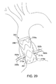
- the first stent 216a overlaps with an aortic annulus 297, as shown in FIG. 20 .
- the first stent may comprise a radial force configured to facilitate fixation within the aortic annulus 297 and prevent migration of the proximal end 222 of the graft 214.
- One or more barbs 225 may be coupled to the first stent 216a to reduce migration of the prosthesis 200.
- the endoluminal prosthesis 200 comprises second and third z-stents 216b and 216c, which are coupled to the graft 214 such that the distal apices of the second stent 216b are aligned with the proximal apices of the third stent 216c.
- At least one fenestration 212 is positioned between a proximal apex of the second stent 216b and a distal apex of the third stent 216c.
- the fifth stent 216e may be configured to engage a healthy portion of a patient's ascending aorta 298, as depicted in the deployed state of FIG. 20 .
- the endoluminal prosthesis 200 further comprises at least one fenestration 212 disposed in a sidewall 274 of the graft 214.
- first and second fenestrations 212a and 212b are disposed in the sidewall 274 at locations distal to the valve replacement 260, as seen in the top view of FIG. 17A .
- the first and second fenestrations 212a and 212b preferably are provided in accordance with the fenestrations 12 described in detail above. Accordingly, at least one of the fenestrations 212a and 212b, and preferably each fenestration, is pivotable in any direction away from an axis perpendicular to a longitudinal axis of the prosthesis.
- Each of the fenestrations 212a and 212b may comprise the first perimeter, the band of flexible material, and the second perimeter described in detail above.
- the band of material of the fenestrations 212a and 212b may have a concave or convex orientation relative to the surface of the graft 214. Further, the band of material may be configured to independently move between an interior surface of the graft 214 and an exterior surface of the graft 214.
- first and second fenestrations are disposed in graft 214 at locations between about 90 and about 270 degrees apart, though the positioning may be greater or less.
- a first branch vessel prosthesis 292a extends between the first fenestration 212a and a first coronary artery 295a in a deployed state
- a second branch vessel prosthesis 292b extends between the second fenestration 212b and a second coronary artery 295b, as depicted in FIG. 20 .
- the branch vessel prostheses 292a and 292b may be provided in accordance with the branch vessel prostheses 92 and 94 of FIG. 13 above.
- delivery and deployment of the graft 214, and the branch vessel prostheses 292a and 292b may be provided in accordance with delivery and deployment of the graft 14 and the branch vessel prostheses 92 and 94, as outlined with respect to FIG. 13 above.
- the branch vessel prostheses 292a and 292b are deployed into the right and left coronary arteries 292a and 292b.
- the pivotable fenestrations 212a and 212b provide the requisite flexibility and ability to pivot so that the branch vessel prostheses 292 and 294 to deploy into the desired position.
- the deployment of the prosthesis 200 into the state shown in FIG. 20 may be achieved in different manners.
- the deployment may be made using a transapical or transeptal approach, in which case the prosthesis 200 may be secured to an exemplary delivery system 270 as shown in FIG. 18 .
- an atraumatic tip 272 of the delivery system is advanced in an antegrade fashion, i.e., in a direction from the aortic annulus 297 towards the ascending aorta 298.
- the deployment may be made using a femoral, carotid, subclavian or axiliary approach, in which case the prosthesis 200 may be secured to the exemplary delivery system 270 as shown in FIG. 19 .
- the atraumatic tip 272 of the delivery system 270 is advanced in a retrograde fashion, i.e., in a direction from the ascending aorta 298 towards the aortic annulus 297.
- the graft 214 may comprise one or more regions 213 that are radially restrained.
- the prosthesis 200 may be provided as part of a preloaded system that includes a guide wire 275.
- a first end segment 276 of the guide wire 276 may enter the lumen 218 through a proximal or distal end of the prosthesis 200, depending on the delivery orientation of the prosthesis shown in FIG. 18 as compared to FIG. 19 .
- the first end segment 276 exits the graft 214 through the first fenestration 212a.
- An intermediate segment of the guide wire 275 may extend external of the graft 214 and reenter the lumen 218 of the prosthesis 200 through the second fenestration 212b.
- a second end segment 277 of the guide wire 275 may extend distally within the lumen 218 and may extend distally to the distal end of the delivery device 270.
- the first end segment 276 of the guide wire 275 may enable introduction of the first branch prosthesis 292a into the first fenestration 212a to couple the prosthesis 200 to the right coronary artery
- the second end segment 277 of the guide wire 277 may enable introduction of the second branch prosthesis 292b into the second fenestration 2212b to couple the prosthesis to the left coronary artery.
- the prosthesis 200 alternatively may be deployed in other parts of a patient's arterial or venous system, or any suitable duct, passageway or vessel.
Landscapes
- Health & Medical Sciences (AREA)
- Engineering & Computer Science (AREA)
- Biomedical Technology (AREA)
- Cardiology (AREA)
- Oral & Maxillofacial Surgery (AREA)
- Transplantation (AREA)
- Heart & Thoracic Surgery (AREA)
- Vascular Medicine (AREA)
- Life Sciences & Earth Sciences (AREA)
- Animal Behavior & Ethology (AREA)
- General Health & Medical Sciences (AREA)
- Public Health (AREA)
- Veterinary Medicine (AREA)
- Gastroenterology & Hepatology (AREA)
- Pulmonology (AREA)
- Prostheses (AREA)
- Media Introduction/Drainage Providing Device (AREA)
Abstract
Description
- This application claims the benefit of priority of
U.S. Utility Application Serial No. 13/335,115 U.S. Utility Patent Application Serial Number 13/213,349, filed August 19, 2011 U.S. Provisional Patent Application Serial Number 61/375,815, filed August 21, 2010 - The functional vessels of human and animal bodies, such as blood vessels and ducts, occasionally weaken or even rupture. For example, the aortic wall can weaken, resulting in an aneurysm, or it may develop a tear in one of the layers of the aortic wall resulting in an aortic dissection.
- One common surgical intervention for weakened, aneurysmal or ruptured passageways or ducts involves the use of an endoluminal prosthesis to provide some or all of the functionality of the original, healthy passageway or duct and/or preserve any remaining vascular integrity by replacing a length of the existing passageway or duct wall that spans the site of failure or defect. Endoluminal prostheses may be of a unitary construction or may be comprised of multiple prosthetic modules. They also may be a single tubular device or a bifurcated branching device depending on the desired application.
- In many cases, however, the damaged or defected portion of the vasculature may include a branch vessel branching from the main vessel. For example, in the case of the abdominal aorta, there are at least three major branch vessels, including the celiac, mesenteric, and renal arteries, as well as other others, leading to various other body organs. Thus, when the damaged portion of the vessel includes one or more of these branch vessels, some accommodation must be made to ensure that the prosthesis does not block or hinder blood flow through the branch vessel. In many instances, there may in insufficient healthy tissue in the aorta near the branching vessels adequately seal a prosthesis without partially or completely blocking one or more of the branching vessels.
- An endoluminal prosthesis comprises a graft having a tubular body comprising proximal and distal ends, and a valve replacement disposed between the proximal and distal ends of the graft. At least one stent is coupled to the graft and has a contracted delivery state and an expanded state for maintaining patency within a portion of the graft. At least one fenestration is disposed in a sidewall of the graft at a location distal to the valve replacement.
- In one embodiment, the at least one fenestration is pivotable in any direction away from an axis perpendicular to a longitudinal axis of the prosthesis. There may be a first perimeter having a first diameter and surrounding the at least one fenestration, a band of flexible material attached to and surrounding the first perimeter and having a flexible frame, and a second perimeter attached to and surrounding the band of flexible material and having a second diameter greater than the first perimeter diameter. The band of material has a first diameter substantially the same as the first perimeter diameter and a second diameter substantially the same as the diameter of the second perimeter. The diameter of the band of material decreases in a direction away from the surface of the graft from the second perimeter to the first perimeter.
- In exemplary embodiments, the band of material has a concave or convex orientation relative to the surface of the graft. The band of material may be configured to independently move between an interior surface of the graft and an exterior surface of the graft.
- In one embodiment, first and second fenestrations may be disposed in the graft at locations between about 90 and about 270 degrees apart. A first branch vessel prosthesis may extend between the first fenestration and a right coronary artery in a deployed state, and a second branch vessel prosthesis may extend between the second fenestration and a left coronary artery in the deployed state.
- The valve replacement may comprise an artificial valve having a tricuspid shape. The valve replacement may be located at the proximal end of the graft, and one or more barbs extend radially outward from the proximal end of the graft.
- Other systems, methods, features and advantages of the invention will be, or will become, apparent to one with skill in the art upon examination of the following figures and detailed description. It is intended that all such additional systems, methods, features and advantages be within the scope of the invention, and be encompassed by the following claims.
- The invention can be better understood with reference to the following drawings and description. The components in the figures are not necessarily to scale, emphasis instead being placed upon illustrating the principles of the invention. Moreover, in the figures, like referenced numerals designate corresponding parts throughout the different views.
-
Figure 1 shows a perspective view of a fenestrated prosthesis having pivotable fenestrations concave (internal) pivotable fenestrations. -
Figure 2 is a partial and internal view of the prosthesis ofFigure 1 . -
Figure 3 shows a perspective view of a fenestrated prosthesis having pivotable fenestrations convex (external) pivotable fenestrations. -
Figure 4 is a partial and internal view of the prosthesis ofFigure 3 . -
Figure 5 shows another fenestrated prosthesis having pivotable fenestrations concave (internal) pivotable fenestrations. -
Figure 6 is an enlarged perspective view of the pivotable fenestration shownFigure 5 . -
Figure 7 shows a fenestrated prosthesis having imageable markers and reinforcement frames. -
Figure 8 is another partial and internal view of an internal pivotable fenestration. -
Figure 9 is a partial, cross-sectional view of a portion of a prosthesis having a pivotable fenestration. -
Figure 10 shows an interior view of a pivotable fenestration where the fenestration is disposed within the lumen of the prosthesis. -
Figure 11 shows an exterior view of a pivotable fenestration where the fenestration is disposed within the lumen of the prosthesis. -
Figure 12 is a prosthesis having a protrusion of graft material to form a fenestration and an extension. -
Figure 13 is a fenestrated prosthesis that has been deployed within a diseased vessel, such as the aorta, where branch vessel prostheses are deployed within the branch vessels. -
Figure 14 shows a branch vessel prosthesis deployed in a secondary branch vessel, where the branch vessel prosthesis is deployed in a right branch vessel positioned lower than its corresponding left branch vessel. -
Figure 15 shows a branch vessel prosthesis deployed in a secondary branch vessel, where the branch vessel prosthesis is deployed in a right branch vessel positioned higher than its corresponding left branch vessel. -
Figure 16 is a side view of an alternative endoluminal prosthesis comprising a valve replacement. -
Figures 17A-17B are, respectively, top and bottom views of the endoluminal prosthesis ofFIG. 16 . -
Figures 18 and 19 are side views of an exemplary delivery system that may be used to deliver the endoluminal prosthesis ofFIG. 16 . -
Figure 20 is a schematic view of illustrating deployment of the endoluminal prosthesis ofFIG. 16 in a patient's anatomy. - The present disclosure relates to an endoluminal prosthesis, such as a stent graft that includes one or more fenestrations to accommodate endovascular disease, such as an aneurysm in cases where one or more side branches is involved, and a side branch prosthesis is deployed within the fenestration to permit fluid flow from the endoluminal prosthesis into the branch vessel. The prosthesis includes fenestrations that pivot as needed to accommodate the dynamic geometry of the aortic branches. In various aspects shown and described in more detail below, for example, one or more pivotable fenestrations provided on a prosthesis lie outside the surface plane of the body of the prosthesis and will allow a branch vessel stent, graft or stent-graft that has been placed in the fenestration to pivot into a variety of orientations required to meet and seal the branch vessel device in the branch vessel. The orientation of the fenestrations may dynamically change over time as needed by changing anatomy.
- Unless defined otherwise, all technical and scientific terms used herein have the same meaning as commonly understood to one of ordinary skill in the art to which this invention belongs.
- The term "distal" means a location or direction that is, or a portion of a device that when implanted is further downstream in the direction of or with respect to blood flow.
- The term "proximal" means a location or direction that is, or a portion of a device that when implanted is further upstream in the direction of or with respect to blood flow.
- The term "fenestration" means an opening provided through a surface of a prosthesis from the interior of the prosthesis to the exterior of the prostheses and may have a variety of geometries, including circular, semi-circular, oval, oblong, as well as other geometries.
- The term "biocompatible" refers to a material that is substantially non-toxic in the in vivo environment of its intended use, and that is not substantially rejected by the patient's physiological system (i.e., is non-antigenic). Examples of biocompatible materials from which textile graft material can be formed include, without limitation, polyesters, such as polyethylene terephthalate; fluorinated polymers, such as polytetrafluoroethylene (PTFE) and fibers of expanded PTFE, and polyurethanes. In addition, materials that are not inherently biocompatible may be subjected to surface modifications in order to render the materials biocompatible. Examples of surface modifications include graft polymerization of biocompatible polymers on the materials surface, coating of the surface with a crosslinked biocompatible polymer, chemical modification with biocompatible functional groups, and immobilization of a compatibilizing agent such as heparin or other biocompatible substances. Thus, any fibrous material having sufficient strength to survive in the in vivo environment may be used to form a textile graft, provided the final textile is biocompatible. Fibers suitable for making textile grafts include polyethylene, polypropylene, polyaramids, polyacrylonitrile, nylon, and cellulose, in addition to the polyesters, fluorinated polymers, and polyurethanes as listed above. Furthermore, bioremodelable materials may also be used singly or in combination with the aforementioned polymer materials. The textile may be made of one or more polymers that do not require treatment or modification to be biocompatible. The graft may be constructed from woven multifilament polyester, for example and without limitation, Dacron™, produced by DuPONT. Dacron™ is known to be sufficiently biologically inert, non-biodegradable, and durable to permit safe insertion inside the human body.
- The term "prosthesis" means any device for insertion or implantation into or replacement for a body part or function of that body part. It may also mean a device that enhances or adds functionality to a physiological system. The term prosthesis may include, for example and without limitation, a stent, stent-graft, filter, valve, balloon, embolization coil, and the like.
- The term "tubular" refers to the general shape of an endoluminal device which allows the module to carry fluid along a distance or fit within a tubular structure such as an artery. Tubular prosthetic devices include single, branched, and bifurcated devices. Tubular may refer to any shape including, but not limited to, tapered, cylindrical, curvilinear, or any combination thereof. A tubular device may have a cross-sectional shape that is, circular, substantially circular or the like. However, it should be understood that the cross-sectional shape is not limited thereto, and other shapes, such as, for example, hexagonal, pentagonal, octagonal, or the like are contemplated. The term "endoluminal" refers to or describes objects that can be placed inside a lumen or a body passageway in a human or animal body. A lumen or a body passageway can be an existing lumen or a lumen created by surgical intervention. As used in this specification, the terms "lumen" or "body passageway" are intended to have a broad meaning and encompasses any duct (e.g., natural or iatrogenic) within the human body and can include a member selected from the group comprising: blood vessels, respiratory ducts, gastrointestinal ducts, and the like. "Endoluminal device" or "endoluminal prosthesis" thus describes devices that can be placed inside one of these lumens.
- The term "graft" or "graft material" describes an object, device, or structure that is joined to or that is capable of being joined to or implanted in or against a body part to enhance, repair, or replace a portion or a function of that body part. A graft by itself or with the addition of other elements, such as structural components, may comprise an endoluminal prosthesis. The graft may be comprised of a single material, a blend of materials, a weave, a laminate, or a composite of two or more materials. The graft may be constructed from natural or organic materials, for example and without limitation, a biological scaffold or bioremodelable material, such as small intestine submucosa ("SIS"), which is commercially available by Cook Biotech, West Lafayette, IN. The graft may also be constructed from a synthetic, for example and without limitation, a polymer. The graft may be formed from a single layer or multiple layers of material. In embodiments employing a plurality of layers of material, the layers may remain separate, or may be attached to each other through a secondary process such as sintering, curing, adhesives, and sutures or the like.
- The term "stent" means any device or structure that adds rigidity, expansion force or support to a prosthesis. A stent is used to obtain and maintain the patency of the body passageway while maintaining the integrity-of the passageway. Also, the stent may be used to form a seal. The stent may be located on the exterior of the device, the interior of the device, or both. A stent may be self-expanding, balloon-expandable or may have characteristics of both. A variety of other stent configurations are also contemplated by the use of the term "stent." The
stents 16 may be comprised of a metallic material selected from stainless steel, silver, platinum, palladium, gold, titanium, tantalum, iridium, tungsten, cobalt, chromium, cobalt-chromium alloy 1058, cobalt-based 35N alloy, nickel-based alloy 625, a molybdenum alloy, a molybdenum alloy including about 0.4% to about 0.8% of lanthanum oxide (Li2O3), and a nickel-titanium alloy, such as nitinol, or other suitable materials as known in the art. The stents may be made of a wire, or may be laser or cannula cut, or manufactured by other known methods. - The term "yarn" refers to a length of a continuous thread or strand of one or more filaments or fibers, with or without twist, suitable for weaving, knitting or otherwise intertwining to form a textile fabric.
- The term "branch vessel" refers to a vessel that branches off from a main vessel. Examples are the celiac and renal arteries which are branch vessels to the aorta (i.e., the main vessel in this context). As another example, the hypogastric artery is a branch vessel to the common iliac, which is a main vessel in this context. Thus, it should be seen that "branch vessel" and "main vessel" are relative terms.
- "Longitudinally" refers to a direction, position or length substantially parallel with a longitudinal axis of a reference, and is the length-wise component of the helical orientation.
- "Circumferentially" refers to a direction, position, or length that encircles a longitudinal axis of reference. The term "circumferential" is not restricted to a full 360° circumferential turn or to a constant radius.
- The terms "patient," "subject," and "recipient" as used in this application refer to any animal, especially humans.
-
Figures 1-8 show afenestrated prosthesis 10, here a stent graft, having a tubular body and comprising a biocompatible material, having one ormore fenestrations 12 pivotable in any direction away from an axis perpendicular to a longitudinal axis of the prosthesis. The pivotable fenestrations 12 have a diameter extending from a sidewall of the graft. The pivotable fenestrations 12 include a first,inner perimeter 26 surrounding thefenestration 12 having a diameter, aband 28 of flexible material attached to and surrounding thefirst perimeter 26, and a second,outer perimeter 30 attached to and surrounding theband 28 of flexible material. Theband 28 of material has a first diameter that is substantially the same as the diameter of thefirst perimeter 26, and a second diameter substantially the same as thesecond perimeter 30. The diameter of the band of material decreases in a direction away from thesurface 20 of thegraft 14 from the second perimeter to the first perimeter. The band of flexible material may include aflexible frame 48. - In some aspects, the
fenestrated prosthesis 10 is intended for placement in the abdominal aorta and to accommodate vessels that branch from the aorta, for example, the renal arteries, and into which a branch vessel prosthesis may be placed. However, thefenestrated prosthesis 10 is not limited for use in the abdominal aorta but may be used in other vessels of the body from which other vessels branch, such as the ascending thoracic aorta, the descending thoracic aorta, as well as other body vessels. -
Figure 1 shows a perspective view of aprosthesis 10 that is a stent graft. Theprosthesis 10 includesgraft material 14 associated with one ormore stents 16. Theprosthesis 10 has aproximal end 22, adistal end 24, and alumen 18 extending through theprosthesis 10 to permit passage of blood flow from theproximal end 22 to thedistal end 24. Thestents 16 may be placed on theexternal surface 20 and/orinternal surface 21 of thegraft material 14. In one particular embodiment, theprosthesis 10, such as that shown inFigure 1 , hasexternal body stents internal stent 16d. Theinternal stent 16d may be a sealing stent and placed at or near theproximal end 22 of theprosthesis 10 to seal theprosthesis 10 at theproximal end 22 to the walls of a blood vessel into which it has been placed. Additionally, or alternatively, depending on the location of the place of theprosthesis 10 or a particular need, a sealingstent 16d may be placed at either or both the proximal and distal ends 22, 24 ofprosthesis 10. Theprosthesis 10 also may include an attachment mechanism, for example, anattachment stent 42, at either or both ends of theprosthesis 10, to further secure theprosthesis 10 within the body vessel and prevent migration of theprosthesis 10. - As shown in
Figure 1 , theprosthesis 10 has several openings or fenestrations that extend from theinternal surface 21 to theexternal surface 20 of thegraft material 14. Theprosthesis 10 ofFigure 1 has twopivotable fenestrations 12, at least onenon-pivotable fenestration 38, and ascallop 40. Here, thescallop 40 is placed at the proximal end of theprosthesis 10. -
Figures 1-8 show various aspects and views of theprosthesis 10 havingpivotable fenestrations 12. Pivotable fenestrations 12 have aninner perimeter 26 surrounding thefenestration 12, aband 28 surrounding theinner perimeter 26, and anouter perimeter 30 surrounding theband 28. As shown, theouter perimeter 30 diameter is greater than theband 28 diameter and theinner perimeter diameter 26. Theinner perimeter 26, theband 28 and theouter perimeter 30 would be substantially concentric with one another if they were in the same plane, for example the surface plane of the graft. Theinner perimeter 26, theband 28 and theouter perimeter 30 may form a hemispherical shape, resembling a dome, or a frustoconical cone extending from the surface of thegraft material 14. Thefenestration 12 is provided at the peak or top of the hemispherical shape or extension. In other embodiments, theband 28 may comprise a tapered, flexible tube extending from theouter perimeter 30 and theinner diameter 26. -
Stents 16, for example those shown in the Figures may be, for example zig zag stents, also known has Z-stents, that comprise a series ofstruts apices 36, although the type of stent used is not so limited. When Z-stents are used, a portion of theouter perimeter 30 of one or more of thefenestrations 12 may lie betweenadjacent struts stents 16. Thestents 16 may be either self-expanding or balloon expandable. Preferably, they are self-expanding. However, a combination of self-expanding and balloon expandable stents also may be contemplated. - As set forth above, the
stents 16 includestruts struts Figure 1 , thestents apices 36 of each row are in circumferential alignment with the bends of longitudinally adjacent rows. In other aspects, as shown inFigure 5 , everybend 36 of each row may be in substantial circumferential alignment with thebends 36 of longitudinally adjacent rows. - The pivotable fenestrations 12 may be located within the
lumen 18 of theprosthesis 10 or extending from the exterior of theprosthesis 10. In the first aspect, the pivotable fenestrations 12 may be said to be concave, relative to theexternal surface 20 of thegraft material 14. In the second aspect, the pivotable fenestrations 12 may be said to be convex, relative to theexternal surface 20 of thegraft material 14.Figure 1 shows the pivotable fenestrations 12 located internal to theprosthesis 10 that is, they lie within thelumen 18 of theprosthesis 10. In the particular aspect shown inFigure 1 , the pivotable fenestrations 12 reside substantially on one side of theprosthesis 10 and are adjacent to one another. In the aspects shown inFigures 3-4 and7-8 , the pivotable fenestrations 12 are positioned to align with, for example, the renal arteries. In other aspects, the one or morepivotable fenestrations 12 may be positioned to align with other branch arteries throughout a diseased vasculature. Additional fenestrations and scallops as disclosed here may also be included. -
Figure 2 , which is a partial internal view of theprosthesis 10 ofFigure 1 , shows a view of theprosthesis 10 looking into thelumen 18 of theprosthesis 10 from theproximal end 22. As shown,pivotable fenestrations 12 extend or protrude into thelumen 18. Pivotable fenestrations 12 have aninner perimeter 26, aband 28, and anouter perimeter 30. As shown inFigure 2 , theouter perimeter 30 lies substantially flush (in the same plane) of thegraft material 14, and theband 28 and theouter perimeter 30 form a hemispherical shape, such as a dome or frustoconical cone extending into thelumen 18. Although both the first andouter perimeters -
Figures 3 and 4 show an aspect of aprosthesis 10 having externally extendingpivotable fenestrations 12.Figure 3 shows a partial view of aprosthesis 10 having two externally extendingpivotable fenestrations 12 extending form opposite sides of theprosthesis 10. As with the other aspects, thefenestrations 12 have aninner perimeter 26 surrounding the fenestration, aband 28 of material surrounding theinner perimeter 26, and anouter perimeter 30 surrounding theband 28 of material.Figure 4 , which is a partial internal view of theprosthesis 10 ofFigure 3 , shows a view of theprosthesis 10 ofFigure 3 , looking into thelumen 18 of theprosthesis 10 from theproximal end 22. As shown,pivotable fenestrations 12 extent or protrude away from theexternal surface 20 of thegraft material 14. Theouter perimeter 30 lies substantially flush (in the same plane) of thegraft material 14, and theband 28 and theouter perimeter 30 form a hemispherical shape, such as a dome, or frustoconical cone extending into thelumen 18. -
Figures 5 and 6 show further aspects of afenestrated prosthesis 10 having at least onepivotable fenestration 12.Figure 5 shows aprosthesis 10 that is a stent graft. The prosthesis includes that has aproximal end 22, adistal end 24, agraft material 14 associated with a series ofexternal stents 16. Theprosthesis 10 further has aninternal sealing stent 16d, andattachment stent 42, and apivotable fenestration 12.Figure 6 shows a partial close up view of the fenestration ofFigure 5 . Thepivotable fenestration 12 shown is anexternal fenestration 12 and has aninner perimeter 26 surrounding thefenestration 12, aband 28 of material surrounding theinner perimeter 26, and anouter perimeter 30 surrounding theband 26. As shown, a portion of theouter perimeter 30 lies betweenstruts most stent 16. Referring back toFigure 5 , theprosthesis 10 includes anon-pivoting fenestration 28 and ascallop 40 at theproximal end 22. As shown in these Figures and throughout the Figures,imageable markers 35, which may be viewed during and after placement of theprosthesis 10 may be placed at various locations on theprosthesis 10 to identify certain aspects of the prosthesis and their location during the implantation procedure and facilitate correct placement of thefenestrations scallop 40, the ends of the prosthesis and the like. For example, as shown inFigure 6 ,markers 35 may be placed about the circumference of theouter perimeter 30. Themarkers 35 may be, for example, sewn or sutured to thegraft material 14, as shown, or may be woven into the graft (not shown). Themarkers 35 also may be placed on the struts of one or more stents, for example, radiopaque marker tubes may be placed about one or more struts of the stent to indicate various areas of the stent graft. As shown, themarkers 35 may be gold, however, any material that may be imaged by way of angiography, fluoroscopy, 3D imaging, MRI, or the like, may be suitable. - As further shown, particularly in
Figures 6-7 , thefenestrations scallop 40 may include areinforcement frame graft 14. For example, inFigures 6-7 , areinforcement frame 44a may be positioned about theouter perimeter 30. As shown inFigure 6 , areinforcement frame 44b may be positioned about theinner perimeter 26. As shown inFigure 7 , in particular, areinforcement frame 44c may be provided about thenon-pivoting fenestration 38, andreinforcement frame 44d may be provided about the perimeter of thescallop 40. The reinforcement frames 44a, 44b, 44c, 44d may be rings. In one preferred aspect, the reinforcement frames 44a, 44b, 44c, 44d are a wire that is sutured about thefenestration scallop 40, to reinforce the fenestration or scallop. The reinforcement frames 44a, 44b, 44c, 44d may be made of any suitable material. One preferred material is a superelastic or shape memory material, such as nitinol. In another preferred embodiment, the reinforcement frames 44a, 44b, 44c, 44d may be made of radiopaque or other imageable material. In another embodiment the reinforcement frames 44a, 44b, 44c, 44d may be solid rings, or may be a wire that is looped about itself into a ring with unattached ends such that the ring may be expanded or contracted in diameter. Suitable frames are disclosed inU.S. Patent Application No. 10/962,632, filed October 12,2004 -
Figure 8 is another partial and internal view of afenestrated prosthesis 10 having two internal pivotable fenestrations 12. As shown in this aspect, a dome-like projection or frustoconical extension is formed within theprosthesis 10. Aflexible frame 48 may be disposed about or within theband 28. - As shown throughout the Figures,
inner perimeter 26,band 28, andouter perimeter 30 surround thepivotable fenestration 12 to create a hemisphere shaped or frustoconical extension or protrusion. Theouter perimeter 30 may be affixed to thegraft material 14 by any attachment method including suturing circumferentially about an aperture disposed throughgraft material 14. Theband 28 may be comprised of the same or different biocompatible material as thegraft material 14. For example, the second biocompatible material may have greater pliability than the first biocompatible graft material used for the tubular graft body. - The
band 28 is sufficiently flexible to permit thefenestration 12 to move such that a branch stent disposed in thefenestration 12 may be oriented upwardly, downwardly, laterally, diagonally and the like. In some aspects, the band has up to about 180 degrees of freedom of movement relative to the surface plane of theprosthesis 10. Accordingly, thepivotable fenestration 12 allows theprosthesis 10 to be used with a variety of patients, due to its ability to adapt to the variance in the positioning of the diseased branch vessels. For example, if a body branch vessel is or becomes offset longitudinally or axially from a pivotingfenestration 12, the pivotingfenestration 12 will pivot the branch vessel prosthesis in the necessary direction and to the necessary degree to maintain the branch vessel prosthesis in place in the branch vessel. -
Figure 9 shows a partial, cross-sectional view of a portion ofprosthesis 10 having apivotable fenestration 12,inner perimeter 26 surroundingfenestration 12,band 28 surroundinginner perimeter 26 and outerperimeter surrounding band 28. Theband 28 may be tapered such that the diameter decreases throughout its depth γ. The depth γ may be determined on the amount of movement required for thepivotable fenestration 12 during use and the ability to cannulate the targeted branch vessel. As the depth γ the amount of second biocompatible material used for theband 28 must also decrease, which limits the range of motion of thepivotable fenestration 12. Furthermore, the depth γ must be large enough in order to cannulate the targeted branch vessel. The depth γ may range from 3 to 10 mm, and preferably is about 6 mm. As shown,inner perimeter 26 has a diameter α that is smaller than the diameter β ofouter perimeter 30. The diameter αinner perimeter 28 may be determined based on the average size of the targeted branch vessel. In this aspect, theprosthesis 10 may be used to repair a diseased renal artery. Accordingly, the average diameter of theinner perimeter 26 may be based on the average of the diameter α of the openings to the renal arteries, or about 6 mm. - The diameter β of the
outer perimeter 30 may be determined based on the desired amount of movement and the desired patency of theprosthesis 10. As the diameter β of theouter perimeter 30 changes, the range of motion also changes. As the diameter β of theouter perimeter 30 decreases, the range of motion also decreases. Additionally, the diameter β of theouter perimeter 30 must be sized to prevent interference with circumferentiallyadjacent struts stents 16. Hence, the diameter β of theouter perimeter 30 may be at most about 15 mm in order to accommodatestents 16. The diameters α and β combined with depth γ provide the requisite amount of surface area forband 28 for thepivotable fenestration 12 to pivot during deployment of a secondary branch prosthesis into thefenestration 12 of after deployment based on dynamic changes to the anatomy. -
Figures 10 and11 show an internal view and an external view, respectively, of apivotable fenestration 12 in an aspect where the fenestration is disposed within thelumen 18 of theprosthesis 10.Figure 10 showspivotable fenestration 12,inner perimeter 26,band 28,outer perimeter 30. Theinner perimeter 26 and outer perimeter 28 areinforcement frame 44a is positioned about theouter perimeter 30. Areinforcement frame 44b is positioned about theinner perimeter 26. As discussed above, the reinforcement frames 44a and 44b may be affixed to the 26outer perimeter 30 andinner perimeter 26 may be, for example, sewn to theouter surface 20 of thegraft material 14.Markers 35 are placed around theinner perimeter 26 in order to facilitate proper placement and alignment of a branch vessel prosthesis and thepivotable fenestration 12. - As shown in
Figure 10 , theband 28 may be provided with aflexible frame 48. Theflexible frame 48 provides support to theband 28 and helps to maintain the overall structure of theband 28 upon deployment within the diseased vessel. Theflexible frame 48 also helps to maintain the patency of thepivotable fenestration 12. Theflexible frame 48 allows to the band of material to reverse orientation and independently move between an interior surface of theprosthesis 10 and an exterior surface of theprosthesis 10 while the device is being deployed. In some embodiments, a physician may alter the orientation of theband 28 during deployment of theprosthesis 10 through the use of endoluminal devices, such as a guidewire catheter. The structure of theflexible frame 48 also prevents thepivotable fenestration 12 from everting or inverting (depending on the initial configuration) once theprosthesis 10 is deployed within the diseased vessel. Theflexible frame 48 may be positioned on theband 28 either on the interior or exterior surface of theband 28. In this particular aspect, theflexible frame 48 is position on the interior surface of theband 28. Theflexible frame 48 comprises a continuous wire formed into a plurality ofsupport units 50 having a generally undulating shape comprising straightened struts 52 interconnected by outwardly facing apices or bends 54. The number ofsupport units 50 may range from about 2 support units to about 10 support units. - In a preferred aspect, the
flexible frame 48 has threesupport units 50. For example, as shown inFigure 10 , the outwardly facingapices 54 may abut or connect to the reinforcingframe 44a of theouter perimeter 30. The outwardly facing apices may be, for example, sewn or sutured to reinforcingframe 44a. Theframe 48 may be bent to form a plurality ofloops Loops apices 52 ofadjacent support units 50. Eachloop frame 44b of theinner perimeter 26. Theloops frame 44b. Aloop 56d may be positioned within an apex 54 of asupport unit 50. Other aspects may comprise other configurations for theflexible frame 48, including, but not limited to, spirals, may be suitable. Theflexible frame 48 may be heat set into the desired configuration prior to attachment toband 28. Theflexible frame 48 may be comprised of an elastic or super elastic material, for example and without limitation, nitinol. -
Figure 11 shows an exterior view of apivotable fenestration 12 where the fenestration is disposed within the lumen of the prosthesis. Thepivotable fenestration 12 has aninner perimeter 26 surrounding thefenestration 12, aband 28 surrounding theinner perimeter 26, and anouter perimeter 30 surrounding theband 28. Theinner perimeter 26 and outer perimeter 28 areinforcement frame 44a is positioned about theouter perimeter 30.Markers 37 may be sewn to around the circumference of theouter perimeter 30 in order to facilitate proper placement and alignment of thepivotable fenestration 12 and the targeted branch vessel. -
Figure 12 shows an embodiment of theband 28 formed from aprotrusion 58 having a bubble like configuration as shown inFigure 12 , as described in co-pendingU.S. Pat. App. No. 12/548,120 . Theprotrusion 58 is integrally formed with the body of theprosthesis 10 and is comprised of a second biocompatible graft material. Theprotrusion 58 may be created during the weaving process used to create thegraft material 14. Theprosthesis 10 may include, but is not limited to, weaves such as plain weaves, basket weaves, rep or rib weaves, twill weaves (e.g., straight twill, reverse twill, herringbone twill), satin weaves, and double weaves (e.g., double-width, tubular double weave, reversed double weave). Desirably, the weave comprises a tubular double layer weave. The fabric may be woven on a table loom, a floor loom, a jacquard loom, a counterbalance loom, a jack loom, or an upright loom. Desirably, the fabric is woven on a floor loom. The fabric may have any configuration possible, but preferably has warp and weft yarns. In one aspect, both the warp yarns and the weft yarns are textile yarns. - In order to create the
protrusion 58, the number of warp yarns used while weaving theprosthesis 10 is increased in the region where the protrusion 315 is desired. While the additional warp yarns are weaved into the prosthesis 310, the number of weft yarns is kept constant. By increasing the number of warp yarns while holding the number of weft yarns constant, the second biocompatible graft material expands outwardly in the radial direction. The number of warp yarns is increased until a pre-determined diameter has been reached. Once the desired depth for theprotrusion 58 is reached, the number of warp yarns introduced into the weaving apparatus is decreased until the number of warp yarns is equal to the number of weft yarns used to form the remainder of theprosthesis 10. A fenestration may be created through theprotrusion 58 by applying heat to the center of theprotrusion 10. Reinforcing frames may be added about the fenestration and adjacent to and surrounding theprotrusion 58 to form the inner andouter perimeters prosthesis 10. Further, aflexible frame 48 may be attached to theprotrusion 58 to maintain it in its desired extended configuration. -
Figure 13 depicts an exemplary prosthesis that has been deployed within adiseased vessel 70, such as the aorta. Theprosthesis 10 comprises atubular graft 72 having asidewall 74 and alumen 76 disposed longitudinally therein. Theprosthesis 10 includes afirst end 78 and asecond end 80. Thetubular graft 72 includes a plurality ofrows outer surface 84 of thetubular graft 72. A sealingstent 86 may be affixed to thefirst end 78 of thetubular graft 72 within the interior surface of thegraft 72. The sealingstent 86 may be attached to thefirst end 78 of thetubular graft 72 by any attaching mechanism, for example and without limitation, suturing.Radiopaque markers 88 may be placed on thetubular graft 72 in order to assist with proper alignment of thetubular graft 72 when deployed within a patient.Fenestrations 90 may be disposed through thetubular graft 72. The distal end (not shown) of theprosthesis 10 may be bifurcated. - The
tubular graft 72 also includes two internal pivotable fenestrations 12 that are in communication with thelumen 76. Thetubular graft 72 may be preloaded onto a delivery device for deployment within a patient. The delivery device includes a sheath over thetubular graft 72 to keep thetubular graft 72 in a compressed state prior to deployment. The delivery device is placed over a guide wire and after checking the appearance and orientation of the device under x-ray, guide wires for eachfenestration 12 are loaded through side ports in the handle of the delivery device. The delivery device is introduced over the guide wire, and advanced until a tapered tip of the delivery device is in the femoral artery and the radiopaque markers indicating thefenestrations 12 are at a level of the appropriate arteries. A sheath is advanced over the guide wire for eachfenestration 12 through each side port on the handle of the device. Once the sheaths for thefenestrations 12 are in position, thetubular graft 72 can be advanced to its correct position and orientation for deployment. Thetubular graft 72 is deployed by withdrawing the sheath covering the graft over the pusher. The operator can perform angiography and adjust the placement of thetubular graft 72 if necessary. Deployment is continued until thetubular graft 72 is fully unsheathed. The sheaths for thefenestrations 12 are advanced over the wires until they are at a level of the lower margin of thefenestration 12. The sheaths for thefenestrations 12 are punctured and a guide wire is advanced through each sheath. A catheter is advanced over the guide wires, and once the catheters are in the target vessels, a stiffer wire replaces the guide wire. The sheaths for thefenestrations 12 are then advanced into the target vessels and branch vessel prostheses are advanced through the sheath and placed in the desired position. -
Figure 13 illustrates in accordance with the procedure described above branch vessel prosthesis deployed through each of the twofenestrations 12.Branch vessel prostheses - As shown in
Figure 13 , thebranch vessel prostheses branch vessels right opening 100 is not completely aligned with theright branch vessel 92. Particularly, theright branch vessel 96 is positioned lower than the correspondingleft branch vessel 98. To accommodate placement of thebranch vessel prosthesis 92 into theright branch vessel 96, thepivotable fenestration 12 provides the requisite flexibility and ability to pivot required for thebranch vessel prosthesis 92 to deploy into the desired position. -
Figures 14 and1 show abranch vessel prosthesis 92 deployed in a secondary branch vessel in greater detail. As shown inFigure 14 , thebranch vessel prosthesis 92 is deployed within theright branch vessel 96, which is positioned lower than its corresponding left branch vessel. Alternatively, as shown inFigure 15 , thebranch vessel prosthesis 92 is deployed within theright branch vessel 102, which is positioned higher than its corresponding left branch vessel. Thepivotable fenestration 12 allows for pivoting motion to accommodate the offset position of the right branch vessel 98,102 and provide access to theright branch vessel - Once a catheter is placed within
right branch vessel branch vessel prosthesis 92 may be deployed within theright branch vessel branch vessel prosthesis 92 may be balloon expandable or self-expandable. In this aspect, thebranch vessel prosthesis 92 is balloon expandable. Once the secondary branch prosthesis 146 is deployed in theright branch vessel branch vessel prosthesis 92 remaining within the interior surface of theprosthesis 10 may be flared in order to provide a proper seal between thefenestration 12 and thebranch vessel - Referring now to
FIGS. 16-19 , analternative endoluminal prosthesis 200 is shown and described. Theprosthesis 200 comprises agraft 214 having a tubular body comprising proximal anddistal ends lumen 218 extending therebetween. - The
prosthesis 200 comprises avalve replacement 260 disposed between theproximal end 222 and thedistal end 224 of thegraft 214. In one example, theartificial valve 260 can be coupled to thegraft 214 with suture. - In one non-limiting example, the valve replacement may comprise an aortic valve designed to replace the function of the recipient's native damaged or poorly performing aortic valve. In other examples, the
prosthesis 200 may be deployed in other arterial locations, i.e., other than the aortic sinus and ascending aorta, or alternatively may be deployed in a patient's venous system, or any suitable duct, passageway or vessel. - In the non-limiting example of an aortic valve, the
artificial valve 260 may be located at theproximal end 222 of thegraft 214, closest to the heart. Theartificial valve 260 preferably includes one ormore leaflets 262, as shown inFIGS. 17A-17B . In this non-limiting example, theartificial valve 260 includes threeleaflets 262, though only two leaflets may be used in a "bicuspid" arrangement. The leaflets are arranged in the prosthesis such that the leaflets mimic a naturally occurring aortic valve. Theartificial valve 260 "opens" to allow blood flow when the pressure on the proximal side of theartificial valve 260 is greater than pressure on the distal side of the artificial valve. Thus, theartificial valve 260 regulates the unidirectional flow of fluid from the heart into the aorta. - The leaflets of the
artificial valve 260 can be fabricated from any at least substantially biocompatible material including such materials as polyester fabrics, polytetrafluoroethylene (PTFE), expanded PTFE, and other synthetic materials known to those of skill in the art. Preferably, the leaflets are fabricated from naturally occurring biomaterials. The leaflets can include a derived collagen material, such as an extracellular matrix. The extracellular matrix can be small intestinal submucosa, stomach submucosa, pericardium, liver basement membrane, urinary bladder submucosa, tissue mucosa, dura mater, or the like. - The
prosthesis 200 further comprises at least one stent coupled to thegraft 214 that has a contracted delivery state and further has an expanded state for maintaining patency within a portion of the graft. In the exemplary embodiment depicted inFIGS. 16 and20 , fiveexemplary stents 216a-216e are provided. As described with respect to thestents 16 above, the stents 216 may be placed on the external surface and/or internal surface of thegraft 214. Like thestents 16 described above, the exemplary stents 216 of theprosthesis 200 comprise zig zag stents, and may be either self-expanding or balloon expandable. - In the embodiment of
FIG. 16 , afirst stent 216a is located at the proximal end of thegraft 214. In use, thefirst stent 216a overlaps with anaortic annulus 297, as shown inFIG. 20 . The first stent may comprise a radial force configured to facilitate fixation within theaortic annulus 297 and prevent migration of theproximal end 222 of thegraft 214. One ormore barbs 225 may be coupled to thefirst stent 216a to reduce migration of theprosthesis 200. - In the example of
FIG. 16 , theendoluminal prosthesis 200 comprises second and third z-stents graft 214 such that the distal apices of thesecond stent 216b are aligned with the proximal apices of thethird stent 216c. At least one fenestration 212 is positioned between a proximal apex of thesecond stent 216b and a distal apex of thethird stent 216c. Thefifth stent 216e may be configured to engage a healthy portion of a patient'sascending aorta 298, as depicted in the deployed state ofFIG. 20 . - The
endoluminal prosthesis 200 further comprises at least one fenestration 212 disposed in asidewall 274 of thegraft 214. In the embodiment ofFIGS. 16-20 , first and second fenestrations 212a and 212b are disposed in thesidewall 274 at locations distal to thevalve replacement 260, as seen in the top view ofFIG. 17A . - The first and second fenestrations 212a and 212b preferably are provided in accordance with the
fenestrations 12 described in detail above. Accordingly, at least one of the fenestrations 212a and 212b, and preferably each fenestration, is pivotable in any direction away from an axis perpendicular to a longitudinal axis of the prosthesis. Each of the fenestrations 212a and 212b may comprise the first perimeter, the band of flexible material, and the second perimeter described in detail above. As described above, the band of material of the fenestrations 212a and 212b may have a concave or convex orientation relative to the surface of thegraft 214. Further, the band of material may be configured to independently move between an interior surface of thegraft 214 and an exterior surface of thegraft 214. - In the non-limiting example of
FIGS. 16-20 , the first and second fenestrations are disposed ingraft 214 at locations between about 90 and about 270 degrees apart, though the positioning may be greater or less. In the deployed state, a firstbranch vessel prosthesis 292a extends between thefirst fenestration 212a and a firstcoronary artery 295a in a deployed state, and a secondbranch vessel prosthesis 292b extends between thesecond fenestration 212b and a secondcoronary artery 295b, as depicted inFIG. 20 . Thebranch vessel prostheses branch vessel prostheses FIG. 13 above. Moreover, delivery and deployment of thegraft 214, and thebranch vessel prostheses graft 14 and thebranch vessel prostheses FIG. 13 above. - In the embodiment of
FIGS. 16-20 , thebranch vessel prostheses coronary arteries - In the examples of
FIGS. 16-20 , the deployment of theprosthesis 200 into the state shown inFIG. 20 may be achieved in different manners. In one example, the deployment may be made using a transapical or transeptal approach, in which case theprosthesis 200 may be secured to anexemplary delivery system 270 as shown inFIG. 18 . In the transapical or transeptal approach, anatraumatic tip 272 of the delivery system is advanced in an antegrade fashion, i.e., in a direction from theaortic annulus 297 towards the ascendingaorta 298. - In another example, the deployment may be made using a femoral, carotid, subclavian or axiliary approach, in which case the
prosthesis 200 may be secured to theexemplary delivery system 270 as shown inFIG. 19 . In this approach, theatraumatic tip 272 of thedelivery system 270 is advanced in a retrograde fashion, i.e., in a direction from the ascendingaorta 298 towards theaortic annulus 297. In either delivery approach, as shown inFIGS. 18-19 , thegraft 214 may comprise one or more regions 213 that are radially restrained. - Further, the
prosthesis 200 may be provided as part of a preloaded system that includes aguide wire 275. In this example, afirst end segment 276 of theguide wire 276 may enter thelumen 218 through a proximal or distal end of theprosthesis 200, depending on the delivery orientation of the prosthesis shown inFIG. 18 as compared toFIG. 19 . Thefirst end segment 276 exits thegraft 214 through thefirst fenestration 212a. An intermediate segment of theguide wire 275 may extend external of thegraft 214 and reenter thelumen 218 of theprosthesis 200 through thesecond fenestration 212b. Asecond end segment 277 of theguide wire 275 may extend distally within thelumen 218 and may extend distally to the distal end of thedelivery device 270. Thefirst end segment 276 of theguide wire 275 may enable introduction of thefirst branch prosthesis 292a into thefirst fenestration 212a to couple theprosthesis 200 to the right coronary artery, and thesecond end segment 277 of theguide wire 277 may enable introduction of thesecond branch prosthesis 292b into the second fenestration 2212b to couple the prosthesis to the left coronary artery. - Further details of a such preloaded wire, and how it may facilitate deployment of stent-grafts into branch vessels, are described in further detail in
U.S. Provisional Patent Application Serial No. 61/579,027 prosthesis 200. - As noted above, while one exemplary use of the
prosthesis 200 has been shown with regard to the aortic sinus and ascending aorta, theprosthesis 200 alternatively may be deployed in other parts of a patient's arterial or venous system, or any suitable duct, passageway or vessel. - While various embodiments of the invention have been described, the invention is not to be restricted except in light of the attached claims and their equivalents. Moreover, the advantages described herein are not necessarily the only advantages of the invention and it is not necessarily expected that every embodiment of the invention will achieve all of the advantages described.
- The features and modifications of all the embodiments may be combined or interchanged as desired.
- The disclosures in United States patent application no.
13/335,115
Claims (15)
- An endoluminal prosthesis comprising:a graft having a tubular body comprising proximal and distal ends;a valve replacement disposed between the proximal and distal ends of the graft;at least one stent coupled to the graft, the at least one stent having a contracted delivery state and an expanded state for maintaining patency within a portion of the graft; andat least one fenestration disposed in a sidewall of the graft at a location distal to the valve replacement.
- The endoluminal prosthesis of claim 1 wherein the at least one fenestration is pivotable in any direction away from an axis perpendicular to a longitudinal axis of the prosthesis
- The endoluminal prosthesis of claim 1 or 2 comprising:a first perimeter having a first diameter and surrounding the at least one fenestration;a band of flexible material attached to and surrounding the first perimeter and having a flexible frame; anda second perimeter attached to and surrounding the band of flexible material and having a second diameter greater than the first perimeter diameter;where the band of material has a first diameter substantially the same as the first perimeter diameter and a second diameter substantially the same as the diameter of the second perimeter, and where the diameter of the band of material decreases in a direction away from the surface of the graft from the second perimeter to the first perimeter.
- The endoluminal prosthesis of claim 3 wherein the band of material has a concave or convex orientation relative to the surface of the graft.
- The endoluminal prosthesis of claim 3 or 4 wherein the band of material is configured to independently move between an interior surface of the graft and an exterior surface of the graft.
- The endoluminal of any preceding claim, wherein first and second fenestrations are disposed in the graft at locations between about 90 and about 270 degrees apart.
- The endoluminal prosthesis of claim 6 further comprising a first branch vessel prosthesis extending between the first fenestration and a right coronary artery in a deployed state, and a second branch vessel prosthesis extending between the second fenestration and a left coronary artery in the deployed state.
- The endoluminal prosthesis of any preceding claim wherein first and second z-stents are coupled to the graft such that the distal apices of the first stent are aligned with the proximal apices of the second stent, and the at least one fenestration is positioned between a proximal apex of the first stent and a distal apex of the second stent.
- The endoluminal prosthesis of any preceding claim wherein the valve replacement comprises an artificial valve having a tricuspid shape.
- The endoluminal prosthesis of any preceding claim wherein the valve replacement is located at the proximal end of the graft, and one or more barbs extend radially outward from the proximal end of the graft.
- An endoluminal prosthesis comprising:a graft having a tubular body comprising proximal and distal ends;a valve replacement disposed between the proximal and distal ends of the graft;at least one stent coupled to the graft, the at least one stent having a contracted delivery state and an expanded state for maintaining patency within a portion of the graft; andat least one fenestration disposed in a sidewall of the graft and pivotable in any direction away from an axis perpendicular to a longitudinal axis of the prosthesis.
- The endoluminal prosthesis of claim 11 where the at least one fenestration is disposed at a location distal to the valve replacement.
- The endoluminal prosthesis of claim 11 or 12 comprising:a first perimeter having a first diameter and surrounding the at least one fenestration;a band of flexible material attached to and surrounding the first perimeter and having a flexible frame; anda second perimeter attached to and surrounding the band of flexible material and having a second diameter greater than the first perimeter diameter;where the band of material has a first diameter substantially the same as the first perimeter diameter and a second diameter substantially the same as the diameter of the second perimeter, and where the diameter of the band of material decreases in a direction away from the surface of the graft from the second perimeter to the first perimeter.
- The endoluminal prosthesis of claim 13 wherein the band of material has a concave or convex orientation relative to the surface of the graft, wherein the band of material is configured to independently move between an interior surface of the graft and an exterior surface of the graft.
- The endoluminal prosthesis of any of claims 11 to 14 wherein first and second fenestrations are disposed in the graft at locations between about 90 and about 270 degrees apart.
Applications Claiming Priority (1)
| Application Number | Priority Date | Filing Date | Title |
|---|---|---|---|
| US13/335,115 US8771336B2 (en) | 2010-08-21 | 2011-12-22 | Endoluminal prosthesis comprising a valve replacement and at least one fenestration |
Publications (2)
| Publication Number | Publication Date |
|---|---|
| EP2606852A1 true EP2606852A1 (en) | 2013-06-26 |
| EP2606852B1 EP2606852B1 (en) | 2016-04-27 |
Family
ID=47627926
Family Applications (1)
| Application Number | Title | Priority Date | Filing Date |
|---|---|---|---|
| EP12198788.7A Active EP2606852B1 (en) | 2011-12-22 | 2012-12-21 | Endoluminal prosthesis comprising a valve replacement and at least one fenestration |
Country Status (3)
| Country | Link |
|---|---|
| EP (1) | EP2606852B1 (en) |
| JP (1) | JP5631965B2 (en) |
| AU (1) | AU2012268911B2 (en) |
Cited By (12)
| Publication number | Priority date | Publication date | Assignee | Title |
|---|---|---|---|---|
| EP3449871A3 (en) * | 2017-09-01 | 2019-06-12 | Cook Medical Technologies LLC | Endoluminal prosthesis with an aortic sinus stent assembly |
| CN110520078A (en) * | 2017-04-04 | 2019-11-29 | 美敦力瓦斯科尔勒公司 | System for loading a transcatheter valve into a delivery catheter |
| CN113367837A (en) * | 2021-05-18 | 2021-09-10 | 罗文达 | General aorta bracket for medical treatment |
| CN113367835A (en) * | 2021-05-18 | 2021-09-10 | 罗文达 | Adjustable aorta medical support |
| EP3446660B1 (en) | 2013-03-11 | 2021-09-29 | Cook Medical Technologies LLC | Endoluminal prosthesis comprising a valve and an axially extendable segment |
| WO2022053809A1 (en) * | 2020-09-09 | 2022-03-17 | Vascutek Limited | Vascular prostheses, delivery systems, and methods to treat aortic aneurysms and dissections |
| US12023236B2 (en) | 2016-09-07 | 2024-07-02 | Vascutek Limited | Hybrid prosthesis and delivery system |
| US12048621B2 (en) | 2017-05-02 | 2024-07-30 | Vascutek Limited | Endoprosthesis |
| US12115059B2 (en) | 2017-09-27 | 2024-10-15 | Vascutek Limited | Endoluminal device |
| US12127961B2 (en) | 2018-12-20 | 2024-10-29 | Vascutek Limited | Stent device |
| US12514724B2 (en) | 2018-12-20 | 2026-01-06 | Vascutek Limited | Stent device delivery tool |
| US12653662B2 (en) | 2019-07-08 | 2026-06-16 | Vascutek Limited | Stent graft prosthesis |
Families Citing this family (16)
| Publication number | Priority date | Publication date | Assignee | Title |
|---|---|---|---|---|
| US8579964B2 (en) | 2010-05-05 | 2013-11-12 | Neovasc Inc. | Transcatheter mitral valve prosthesis |
| US9308087B2 (en) | 2011-04-28 | 2016-04-12 | Neovasc Tiara Inc. | Sequentially deployed transcatheter mitral valve prosthesis |
| US9554897B2 (en) | 2011-04-28 | 2017-01-31 | Neovasc Tiara Inc. | Methods and apparatus for engaging a valve prosthesis with tissue |
| US9345573B2 (en) | 2012-05-30 | 2016-05-24 | Neovasc Tiara Inc. | Methods and apparatus for loading a prosthesis onto a delivery system |
| US9572665B2 (en) | 2013-04-04 | 2017-02-21 | Neovasc Tiara Inc. | Methods and apparatus for delivering a prosthetic valve to a beating heart |
| JP7002451B2 (en) | 2015-12-15 | 2022-01-20 | ニオバスク ティアラ インコーポレイテッド | Transseptal delivery system |
| CN108882981B (en) | 2016-01-29 | 2021-08-10 | 内奥瓦斯克迪亚拉公司 | Prosthetic valve for preventing outflow obstruction |
| AU2017361296B2 (en) | 2016-11-21 | 2022-09-29 | Neovasc Inc. | Methods and systems for rapid retraction of a transcatheter heart valve delivery system |
| EP3672530A4 (en) | 2017-08-25 | 2021-04-14 | Neovasc Tiara Inc. | SEQUENTIAL DEPLOYMENT TRANSCATHETER MITRAL VALVE PROSTHESIS |
| AU2019374743B2 (en) | 2018-11-08 | 2022-03-03 | Neovasc Inc. | Ventricular deployment of a transcatheter mitral valve prosthesis |
| CN113747863B (en) | 2019-03-08 | 2024-11-08 | 内奥瓦斯克迪亚拉公司 | Retrievable Prosthesis Delivery System |
| AU2020256195B2 (en) | 2019-04-01 | 2022-10-13 | Neovasc Inc. | Controllably deployable prosthetic valve |
| US11491006B2 (en) | 2019-04-10 | 2022-11-08 | Neovasc Tiara Inc. | Prosthetic valve with natural blood flow |
| CA3282225A1 (en) | 2019-05-20 | 2026-03-02 | Neovasc Tiara Inc. | Introducer with hemostasis mechanism |
| JP7520897B2 (en) | 2019-06-20 | 2024-07-23 | ニオバスク ティアラ インコーポレイテッド | Thin prosthetic mitral valve |
| CA3199943A1 (en) * | 2020-08-24 | 2022-03-03 | Edwards Lifesciences Corporation | Balloon cover for a delivery apparatus for an expandable prosthetic heart valve |
Citations (7)
| Publication number | Priority date | Publication date | Assignee | Title |
|---|---|---|---|---|
| US20050222674A1 (en) * | 2004-03-31 | 2005-10-06 | Med Institute, Inc. | Endoluminal graft with a prosthetic valve |
| EP1673039A1 (en) * | 2003-10-10 | 2006-06-28 | William A. Cook Australia Pty. Ltd. | Stent graft fenestration |
| EP1847234A1 (en) * | 2006-04-18 | 2007-10-24 | Medtronic Vascular, Inc. | Device for controlling the positioning of a stent graft fenestration |
| US20080275548A1 (en) * | 2006-11-03 | 2008-11-06 | The Cleveland Clinic Foundation | Apparatus for repairing the function of a native aortic valve |
| US20090030502A1 (en) * | 2007-07-26 | 2009-01-29 | Jichao Sun | Socket For Fenestrated Tubular Prosthesis |
| US20100268327A1 (en) * | 2009-04-17 | 2010-10-21 | Medtronic Vascular, Inc. | Mobile External Coupling for Branch Vessel Connection |
| US20110166644A1 (en) * | 2008-02-22 | 2011-07-07 | Barts and The Londhon NHS Trust | Blood vessel prosthesis and delivery apparatus |
Family Cites Families (4)
| Publication number | Priority date | Publication date | Assignee | Title |
|---|---|---|---|---|
| US8808351B2 (en) * | 2003-10-10 | 2014-08-19 | Cook Medical Technologies Llc | Stretchable prosthesis fenestration |
| US8828074B2 (en) * | 2006-04-21 | 2014-09-09 | Medtronic Vascular, Inc. | Stent graft having short tube graft for branch vessel |
| WO2010024849A1 (en) * | 2008-08-29 | 2010-03-04 | Cook Incorporated | Prosthesis with moveable fenestration |
| US8506622B2 (en) * | 2009-04-17 | 2013-08-13 | Medtronic Vascular, Inc. | Mobile external coupling for branch vessel connection |
-
2012
- 2012-12-20 AU AU2012268911A patent/AU2012268911B2/en active Active
- 2012-12-21 JP JP2012278799A patent/JP5631965B2/en active Active
- 2012-12-21 EP EP12198788.7A patent/EP2606852B1/en active Active
Patent Citations (7)
| Publication number | Priority date | Publication date | Assignee | Title |
|---|---|---|---|---|
| EP1673039A1 (en) * | 2003-10-10 | 2006-06-28 | William A. Cook Australia Pty. Ltd. | Stent graft fenestration |
| US20050222674A1 (en) * | 2004-03-31 | 2005-10-06 | Med Institute, Inc. | Endoluminal graft with a prosthetic valve |
| EP1847234A1 (en) * | 2006-04-18 | 2007-10-24 | Medtronic Vascular, Inc. | Device for controlling the positioning of a stent graft fenestration |
| US20080275548A1 (en) * | 2006-11-03 | 2008-11-06 | The Cleveland Clinic Foundation | Apparatus for repairing the function of a native aortic valve |
| US20090030502A1 (en) * | 2007-07-26 | 2009-01-29 | Jichao Sun | Socket For Fenestrated Tubular Prosthesis |
| US20110166644A1 (en) * | 2008-02-22 | 2011-07-07 | Barts and The Londhon NHS Trust | Blood vessel prosthesis and delivery apparatus |
| US20100268327A1 (en) * | 2009-04-17 | 2010-10-21 | Medtronic Vascular, Inc. | Mobile External Coupling for Branch Vessel Connection |
Cited By (13)
| Publication number | Priority date | Publication date | Assignee | Title |
|---|---|---|---|---|
| EP3446660B1 (en) | 2013-03-11 | 2021-09-29 | Cook Medical Technologies LLC | Endoluminal prosthesis comprising a valve and an axially extendable segment |
| US12690960B2 (en) | 2016-09-07 | 2026-07-28 | Vascutek Limited | Hybrid prosthesis and delivery system |
| US12023236B2 (en) | 2016-09-07 | 2024-07-02 | Vascutek Limited | Hybrid prosthesis and delivery system |
| CN110520078A (en) * | 2017-04-04 | 2019-11-29 | 美敦力瓦斯科尔勒公司 | System for loading a transcatheter valve into a delivery catheter |
| US12048621B2 (en) | 2017-05-02 | 2024-07-30 | Vascutek Limited | Endoprosthesis |
| EP3449871A3 (en) * | 2017-09-01 | 2019-06-12 | Cook Medical Technologies LLC | Endoluminal prosthesis with an aortic sinus stent assembly |
| US12115059B2 (en) | 2017-09-27 | 2024-10-15 | Vascutek Limited | Endoluminal device |
| US12127961B2 (en) | 2018-12-20 | 2024-10-29 | Vascutek Limited | Stent device |
| US12514724B2 (en) | 2018-12-20 | 2026-01-06 | Vascutek Limited | Stent device delivery tool |
| US12653662B2 (en) | 2019-07-08 | 2026-06-16 | Vascutek Limited | Stent graft prosthesis |
| WO2022053809A1 (en) * | 2020-09-09 | 2022-03-17 | Vascutek Limited | Vascular prostheses, delivery systems, and methods to treat aortic aneurysms and dissections |
| CN113367835A (en) * | 2021-05-18 | 2021-09-10 | 罗文达 | Adjustable aorta medical support |
| CN113367837A (en) * | 2021-05-18 | 2021-09-10 | 罗文达 | General aorta bracket for medical treatment |
Also Published As
| Publication number | Publication date |
|---|---|
| JP5631965B2 (en) | 2014-11-26 |
| EP2606852B1 (en) | 2016-04-27 |
| AU2012268911A1 (en) | 2013-07-11 |
| JP2013132558A (en) | 2013-07-08 |
| AU2012268911B2 (en) | 2014-04-24 |
Similar Documents
| Publication | Publication Date | Title |
|---|---|---|
| EP2606852B1 (en) | Endoluminal prosthesis comprising a valve replacement and at least one fenestration | |
| US10188503B2 (en) | Prosthesis having pivoting fenestration | |
| US10159560B2 (en) | Prosthesis having pivoting fenestration | |
| US8771336B2 (en) | Endoluminal prosthesis comprising a valve replacement and at least one fenestration | |
| US20230293284A1 (en) | Endoluminal prosthesis having multiple branches or fenestrations and methods of deployment | |
| US8702786B2 (en) | Prosthesis having pivoting fenestration | |
| AU2013273687B2 (en) | Prosthesis having pivoting fenestration | |
| US9351822B2 (en) | Prosthesis having pivoting fenestration | |
| EP3449871A2 (en) | Endoluminal prosthesis with an aortic sinus stent assembly | |
| EP2709556A1 (en) | Prosthesis |
Legal Events
| Date | Code | Title | Description |
|---|---|---|---|
| AK | Designated contracting states |
Kind code of ref document: A1 Designated state(s): AL AT BE BG CH CY CZ DE DK EE ES FI FR GB GR HR HU IE IS IT LI LT LU LV MC MK MT NL NO PL PT RO RS SE SI SK SM TR |
|
| AX | Request for extension of the european patent |
Extension state: BA ME |
|
| PUAI | Public reference made under article 153(3) epc to a published international application that has entered the european phase |
Free format text: ORIGINAL CODE: 0009012 |
|
| 17P | Request for examination filed |
Effective date: 20131223 |
|
| RBV | Designated contracting states (corrected) |
Designated state(s): AL AT BE BG CH CY CZ DE DK EE ES FI FR GB GR HR HU IE IS IT LI LT LU LV MC MK MT NL NO PL PT RO RS SE SI SK SM TR |
|
| 17Q | First examination report despatched |
Effective date: 20150504 |
|
| GRAP | Despatch of communication of intention to grant a patent |
Free format text: ORIGINAL CODE: EPIDOSNIGR1 |
|
| RIC1 | Information provided on ipc code assigned before grant |
Ipc: A61F 2/962 20130101ALN20151020BHEP Ipc: A61F 2/954 20130101ALN20151020BHEP Ipc: A61F 2/07 20130101AFI20151020BHEP Ipc: A61F 2/24 20060101ALI20151020BHEP |
|
| INTG | Intention to grant announced |
Effective date: 20151125 |
|
| GRAS | Grant fee paid |
Free format text: ORIGINAL CODE: EPIDOSNIGR3 |
|
| GRAA | (expected) grant |
Free format text: ORIGINAL CODE: 0009210 |
|
| AK | Designated contracting states |
Kind code of ref document: B1 Designated state(s): AL AT BE BG CH CY CZ DE DK EE ES FI FR GB GR HR HU IE IS IT LI LT LU LV MC MK MT NL NO PL PT RO RS SE SI SK SM TR |
|
| REG | Reference to a national code |
Ref country code: GB Ref legal event code: FG4D |
|
| REG | Reference to a national code |
Ref country code: CH Ref legal event code: EP |
|
| REG | Reference to a national code |
Ref country code: AT Ref legal event code: REF Ref document number: 793893 Country of ref document: AT Kind code of ref document: T Effective date: 20160515 |
|
| REG | Reference to a national code |
Ref country code: IE Ref legal event code: FG4D |
|
| REG | Reference to a national code |
Ref country code: DE Ref legal event code: R096 Ref document number: 602012017616 Country of ref document: DE |
|
| REG | Reference to a national code |
Ref country code: LT Ref legal event code: MG4D |
|
| REG | Reference to a national code |
Ref country code: NL Ref legal event code: MP Effective date: 20160427 |
|
| REG | Reference to a national code |
Ref country code: AT Ref legal event code: MK05 Ref document number: 793893 Country of ref document: AT Kind code of ref document: T Effective date: 20160427 |
|
| PG25 | Lapsed in a contracting state [announced via postgrant information from national office to epo] |
Ref country code: NL Free format text: LAPSE BECAUSE OF FAILURE TO SUBMIT A TRANSLATION OF THE DESCRIPTION OR TO PAY THE FEE WITHIN THE PRESCRIBED TIME-LIMIT Effective date: 20160427 |
|
| PG25 | Lapsed in a contracting state [announced via postgrant information from national office to epo] |
Ref country code: LT Free format text: LAPSE BECAUSE OF FAILURE TO SUBMIT A TRANSLATION OF THE DESCRIPTION OR TO PAY THE FEE WITHIN THE PRESCRIBED TIME-LIMIT Effective date: 20160427 Ref country code: FI Free format text: LAPSE BECAUSE OF FAILURE TO SUBMIT A TRANSLATION OF THE DESCRIPTION OR TO PAY THE FEE WITHIN THE PRESCRIBED TIME-LIMIT Effective date: 20160427 Ref country code: PL Free format text: LAPSE BECAUSE OF FAILURE TO SUBMIT A TRANSLATION OF THE DESCRIPTION OR TO PAY THE FEE WITHIN THE PRESCRIBED TIME-LIMIT Effective date: 20160427 Ref country code: NO Free format text: LAPSE BECAUSE OF FAILURE TO SUBMIT A TRANSLATION OF THE DESCRIPTION OR TO PAY THE FEE WITHIN THE PRESCRIBED TIME-LIMIT Effective date: 20160727 |
|
| PG25 | Lapsed in a contracting state [announced via postgrant information from national office to epo] |
Ref country code: LV Free format text: LAPSE BECAUSE OF FAILURE TO SUBMIT A TRANSLATION OF THE DESCRIPTION OR TO PAY THE FEE WITHIN THE PRESCRIBED TIME-LIMIT Effective date: 20160427 Ref country code: GR Free format text: LAPSE BECAUSE OF FAILURE TO SUBMIT A TRANSLATION OF THE DESCRIPTION OR TO PAY THE FEE WITHIN THE PRESCRIBED TIME-LIMIT Effective date: 20160728 Ref country code: HR Free format text: LAPSE BECAUSE OF FAILURE TO SUBMIT A TRANSLATION OF THE DESCRIPTION OR TO PAY THE FEE WITHIN THE PRESCRIBED TIME-LIMIT Effective date: 20160427 Ref country code: ES Free format text: LAPSE BECAUSE OF FAILURE TO SUBMIT A TRANSLATION OF THE DESCRIPTION OR TO PAY THE FEE WITHIN THE PRESCRIBED TIME-LIMIT Effective date: 20160427 Ref country code: AT Free format text: LAPSE BECAUSE OF FAILURE TO SUBMIT A TRANSLATION OF THE DESCRIPTION OR TO PAY THE FEE WITHIN THE PRESCRIBED TIME-LIMIT Effective date: 20160427 Ref country code: RS Free format text: LAPSE BECAUSE OF FAILURE TO SUBMIT A TRANSLATION OF THE DESCRIPTION OR TO PAY THE FEE WITHIN THE PRESCRIBED TIME-LIMIT Effective date: 20160427 Ref country code: PT Free format text: LAPSE BECAUSE OF FAILURE TO SUBMIT A TRANSLATION OF THE DESCRIPTION OR TO PAY THE FEE WITHIN THE PRESCRIBED TIME-LIMIT Effective date: 20160829 Ref country code: SE Free format text: LAPSE BECAUSE OF FAILURE TO SUBMIT A TRANSLATION OF THE DESCRIPTION OR TO PAY THE FEE WITHIN THE PRESCRIBED TIME-LIMIT Effective date: 20160427 |
|
| PG25 | Lapsed in a contracting state [announced via postgrant information from national office to epo] |
Ref country code: IT Free format text: LAPSE BECAUSE OF FAILURE TO SUBMIT A TRANSLATION OF THE DESCRIPTION OR TO PAY THE FEE WITHIN THE PRESCRIBED TIME-LIMIT Effective date: 20160427 Ref country code: BE Free format text: LAPSE BECAUSE OF FAILURE TO SUBMIT A TRANSLATION OF THE DESCRIPTION OR TO PAY THE FEE WITHIN THE PRESCRIBED TIME-LIMIT Effective date: 20160427 |
|
| REG | Reference to a national code |
Ref country code: DE Ref legal event code: R097 Ref document number: 602012017616 Country of ref document: DE |
|
| PG25 | Lapsed in a contracting state [announced via postgrant information from national office to epo] |
Ref country code: EE Free format text: LAPSE BECAUSE OF FAILURE TO SUBMIT A TRANSLATION OF THE DESCRIPTION OR TO PAY THE FEE WITHIN THE PRESCRIBED TIME-LIMIT Effective date: 20160427 Ref country code: DK Free format text: LAPSE BECAUSE OF FAILURE TO SUBMIT A TRANSLATION OF THE DESCRIPTION OR TO PAY THE FEE WITHIN THE PRESCRIBED TIME-LIMIT Effective date: 20160427 Ref country code: RO Free format text: LAPSE BECAUSE OF FAILURE TO SUBMIT A TRANSLATION OF THE DESCRIPTION OR TO PAY THE FEE WITHIN THE PRESCRIBED TIME-LIMIT Effective date: 20160427 Ref country code: SK Free format text: LAPSE BECAUSE OF FAILURE TO SUBMIT A TRANSLATION OF THE DESCRIPTION OR TO PAY THE FEE WITHIN THE PRESCRIBED TIME-LIMIT Effective date: 20160427 Ref country code: CZ Free format text: LAPSE BECAUSE OF FAILURE TO SUBMIT A TRANSLATION OF THE DESCRIPTION OR TO PAY THE FEE WITHIN THE PRESCRIBED TIME-LIMIT Effective date: 20160427 |
|
| PG25 | Lapsed in a contracting state [announced via postgrant information from national office to epo] |
Ref country code: SM Free format text: LAPSE BECAUSE OF FAILURE TO SUBMIT A TRANSLATION OF THE DESCRIPTION OR TO PAY THE FEE WITHIN THE PRESCRIBED TIME-LIMIT Effective date: 20160427 |
|
| PLBE | No opposition filed within time limit |
Free format text: ORIGINAL CODE: 0009261 |
|
| STAA | Information on the status of an ep patent application or granted ep patent |
Free format text: STATUS: NO OPPOSITION FILED WITHIN TIME LIMIT |
|
| 26N | No opposition filed |
Effective date: 20170130 |
|
| PG25 | Lapsed in a contracting state [announced via postgrant information from national office to epo] |
Ref country code: SI Free format text: LAPSE BECAUSE OF FAILURE TO SUBMIT A TRANSLATION OF THE DESCRIPTION OR TO PAY THE FEE WITHIN THE PRESCRIBED TIME-LIMIT Effective date: 20160427 |
|
| REG | Reference to a national code |
Ref country code: CH Ref legal event code: PL |
|
| PG25 | Lapsed in a contracting state [announced via postgrant information from national office to epo] |
Ref country code: MC Free format text: LAPSE BECAUSE OF FAILURE TO SUBMIT A TRANSLATION OF THE DESCRIPTION OR TO PAY THE FEE WITHIN THE PRESCRIBED TIME-LIMIT Effective date: 20160427 |
|
| REG | Reference to a national code |
Ref country code: FR Ref legal event code: ST Effective date: 20170831 |
|
| PG25 | Lapsed in a contracting state [announced via postgrant information from national office to epo] |
Ref country code: LI Free format text: LAPSE BECAUSE OF NON-PAYMENT OF DUE FEES Effective date: 20161231 Ref country code: CH Free format text: LAPSE BECAUSE OF NON-PAYMENT OF DUE FEES Effective date: 20161231 Ref country code: FR Free format text: LAPSE BECAUSE OF NON-PAYMENT OF DUE FEES Effective date: 20170102 Ref country code: LU Free format text: LAPSE BECAUSE OF NON-PAYMENT OF DUE FEES Effective date: 20161221 |
|
| PG25 | Lapsed in a contracting state [announced via postgrant information from national office to epo] |
Ref country code: HU Free format text: LAPSE BECAUSE OF FAILURE TO SUBMIT A TRANSLATION OF THE DESCRIPTION OR TO PAY THE FEE WITHIN THE PRESCRIBED TIME-LIMIT; INVALID AB INITIO Effective date: 20121221 Ref country code: CY Free format text: LAPSE BECAUSE OF FAILURE TO SUBMIT A TRANSLATION OF THE DESCRIPTION OR TO PAY THE FEE WITHIN THE PRESCRIBED TIME-LIMIT Effective date: 20160427 |
|
| PG25 | Lapsed in a contracting state [announced via postgrant information from national office to epo] |
Ref country code: MK Free format text: LAPSE BECAUSE OF FAILURE TO SUBMIT A TRANSLATION OF THE DESCRIPTION OR TO PAY THE FEE WITHIN THE PRESCRIBED TIME-LIMIT Effective date: 20160427 Ref country code: TR Free format text: LAPSE BECAUSE OF FAILURE TO SUBMIT A TRANSLATION OF THE DESCRIPTION OR TO PAY THE FEE WITHIN THE PRESCRIBED TIME-LIMIT Effective date: 20160427 Ref country code: IS Free format text: LAPSE BECAUSE OF FAILURE TO SUBMIT A TRANSLATION OF THE DESCRIPTION OR TO PAY THE FEE WITHIN THE PRESCRIBED TIME-LIMIT Effective date: 20160427 |
|
| PG25 | Lapsed in a contracting state [announced via postgrant information from national office to epo] |
Ref country code: BG Free format text: LAPSE BECAUSE OF FAILURE TO SUBMIT A TRANSLATION OF THE DESCRIPTION OR TO PAY THE FEE WITHIN THE PRESCRIBED TIME-LIMIT Effective date: 20160427 |
|
| PG25 | Lapsed in a contracting state [announced via postgrant information from national office to epo] |
Ref country code: MT Free format text: LAPSE BECAUSE OF NON-PAYMENT OF DUE FEES Effective date: 20161221 |
|
| PG25 | Lapsed in a contracting state [announced via postgrant information from national office to epo] |
Ref country code: AL Free format text: LAPSE BECAUSE OF FAILURE TO SUBMIT A TRANSLATION OF THE DESCRIPTION OR TO PAY THE FEE WITHIN THE PRESCRIBED TIME-LIMIT Effective date: 20160427 |
|
| P01 | Opt-out of the competence of the unified patent court (upc) registered |
Effective date: 20230602 |
|
| PGFP | Annual fee paid to national office [announced via postgrant information from national office to epo] |
Ref country code: GB Payment date: 20251223 Year of fee payment: 14 |
|
| PGFP | Annual fee paid to national office [announced via postgrant information from national office to epo] |
Ref country code: IE Payment date: 20251218 Year of fee payment: 14 |
|
| PGFP | Annual fee paid to national office [announced via postgrant information from national office to epo] |
Ref country code: DE Payment date: 20251229 Year of fee payment: 14 |