EP2606796A2 - Dust collector for cleaning a filter - Google Patents
Dust collector for cleaning a filter Download PDFInfo
- Publication number
- EP2606796A2 EP2606796A2 EP12193026.7A EP12193026A EP2606796A2 EP 2606796 A2 EP2606796 A2 EP 2606796A2 EP 12193026 A EP12193026 A EP 12193026A EP 2606796 A2 EP2606796 A2 EP 2606796A2
- Authority
- EP
- European Patent Office
- Prior art keywords
- opening
- closing
- filter
- closing member
- dust collector
- Prior art date
- Legal status (The legal status is an assumption and is not a legal conclusion. Google has not performed a legal analysis and makes no representation as to the accuracy of the status listed.)
- Granted
Links
Images







Classifications
-
- B—PERFORMING OPERATIONS; TRANSPORTING
- B01—PHYSICAL OR CHEMICAL PROCESSES OR APPARATUS IN GENERAL
- B01D—SEPARATION
- B01D46/00—Filters or filtering processes specially modified for separating dispersed particles from gases or vapours
- B01D46/66—Regeneration of the filtering material or filter elements inside the filter
- B01D46/70—Regeneration of the filtering material or filter elements inside the filter by acting counter-currently on the filtering surface, e.g. by flushing on the non-cake side of the filter
- B01D46/71—Regeneration of the filtering material or filter elements inside the filter by acting counter-currently on the filtering surface, e.g. by flushing on the non-cake side of the filter with pressurised gas, e.g. pulsed air
-
- A—HUMAN NECESSITIES
- A47—FURNITURE; DOMESTIC ARTICLES OR APPLIANCES; COFFEE MILLS; SPICE MILLS; SUCTION CLEANERS IN GENERAL
- A47L—DOMESTIC WASHING OR CLEANING; SUCTION CLEANERS IN GENERAL
- A47L5/00—Structural features of suction cleaners
- A47L5/12—Structural features of suction cleaners with power-driven air-pumps or air-compressors, e.g. driven by motor vehicle engine vacuum
- A47L5/22—Structural features of suction cleaners with power-driven air-pumps or air-compressors, e.g. driven by motor vehicle engine vacuum with rotary fans
- A47L5/28—Suction cleaners with handles and nozzles fixed on the casings, e.g. wheeled suction cleaners with steering handle
-
- A—HUMAN NECESSITIES
- A47—FURNITURE; DOMESTIC ARTICLES OR APPLIANCES; COFFEE MILLS; SPICE MILLS; SUCTION CLEANERS IN GENERAL
- A47L—DOMESTIC WASHING OR CLEANING; SUCTION CLEANERS IN GENERAL
- A47L9/00—Details or accessories of suction cleaners, e.g. mechanical means for controlling the suction or for effecting pulsating action; Storing devices specially adapted to suction cleaners or parts thereof; Carrying-vehicles specially adapted for suction cleaners
- A47L9/20—Means for cleaning filters
Definitions
- the vent hole of the tilted portion provided on the downstream side of the communication path in the intake path is opened.
- the space for air flow is retained sufficiently between each of the first opening and closing members in the normal state and the tilted portion. Accordingly, the intake paths can be opened in the normal state.
- the vent hole is closed and the space for air flow is eliminated, whereby each intake path can be closed.
- the air that has flown into the intake passage 33 flows through the vent hole 58' of the tilted wall 57' and the space for air flow 59' into the hollow portion 14 of the filter fixing member 10. Then, the air flows through the vent hole H (see FIG. 11 ) of the fan cover 30 from the inlet port 26 (see FIG. 11 ) of the main body case 11, and is guided into the fan cover 30. Similarly, the air that has flown into the intake passage 34 flows through the vent hole 58 of the tilted wall 57 and the space for air flow 59 into the hollow portion 14 of the filter fixing member 10. Then, the air flows through the vent hole H (see FIG. 11 ) of the fan cover 30 from the inlet port 26 (see FIG.
- the tank 3 and the main body case 11 has a negative pressure. Accordingly, the discharged air that has passed through the discharge passage 44 is guided from the inlet port 53 into the intake passage 34 as shown by two-dot chain arrow in FIG. 4 .
- the discharged air in the intake passage 34 flows backward from the downstream side to the upstream side in the intake passage 34, and into the right filter 22 through the long hole 15. Then, the discharged air sequentially flows through the right filter 22, the right filter 23, and the right prefilter 20, and returns to the tank 3. At this time, the discharged air flowing backward can blow away the dust caught by the filters 20, 22, 23.
- the present invention is not limited to the above embodiment, and the configuration can be partially modified as appropriate without departing from the scope of the invention.
- the first opening and closing member 55 of the intake passage 34 may be biased by the other DC motor and the other cam member to the position where the vent hole 58 is closed.
- the paper filter 22 may be subjected to an antistatic treatment.
Landscapes
- Engineering & Computer Science (AREA)
- Mechanical Engineering (AREA)
- Chemical & Material Sciences (AREA)
- Chemical Kinetics & Catalysis (AREA)
- Filtering Of Dispersed Particles In Gases (AREA)
- Electric Suction Cleaners (AREA)
- Filters For Electric Vacuum Cleaners (AREA)
- Electrostatic Separation (AREA)
Abstract
Description
- The present invention relates to dust collectors that include, in an upper part of a tank having a suction port, a main body having an electric blower, and that draw air through the suction port from outside by the electric blower, and catch dust in the air by a filter provided in the tank.
- For example, Japanese Patent No.
3,457,929 - For example, in the case where two air inlet pipes are provided in this dust collector, an electromagnetic valve of one of the air inlet pipes is opened, and an electromagnetic valve of the other air inlet pipe is closed during operation of the dust collector. Thus, the dust adhering to a part of the filter group is removed by using the one air inlet pipe, whereby the part of the filter group can be cleaned while capturing dust by another part of the filter group.
- However, since the above dust collector uses the electromagnetic valves to open and close the air inlet pipes, a device that electrically controls electromagnets that drive the electromagnetic valves is required, which may complicate the structure of the dust collector.
- It is an object of the present invention to provide a dust collector capable of cleaning a filter during operation with a simple structure.
- According to a first aspect of the present invention, in a dust collector, a main body including an electric blower is provided in an upper part of a tank having a suction port, air drawn through the suction port from outside by the electric blower is discharged through the tank and the main body, and a filter that separates the suction port from the main body in an intake path extending from the suction port to the electric blower and that is capable of catching dust in the air is provided in the tank. In the dust collector, a pair of the intake paths in which air flows respectively through a pair of the filters projecting within the tank are formed so as to be combined together on an upstream side of the electric blower, a pair of communication paths are formed so as to allow a discharge passage on a downstream side of the electric blower to communicate with each of the intake paths, first opening and closing members are each provided on a downstream side of the communication path in the intake path, are capable of opening and closing the intake path, and are biased, in a normal state, to a position where the first opening and closing member opens the intake path, second opening and closing members are each provided in the communication path, are capable of opening and closing the communication path, are biased, in the normal state, to a position where the second opening and closing member closes the communication path, and open the communication path in response to a closing operation of closing the intake path by the first opening and closing member, and an operation unit is provided that is capable of alternately causing the first opening and closing members in the intake paths to perform the closing operation. In the dust collector, when the operation unit causes one of the first opening and closing members to perform the closing operation and thus causes the second opening and closing member to open the communication path, discharged air in the discharge passage is guided to one of the intake paths via the communication path, the discharged air is caused to flow backward in the intake path and returned to the tank through the filter, and is combined to the other intake path, so that the dust on the filter of the one intake path is removed.
- According to a second aspect of the present invention, in the first aspect, the operation unit includes a motor placed between the pair of first opening and closing members, and a cam member provided on an output shaft of the motor and formed to alternately contact the first opening and closing members respectively in response to rotation of the output shaft so that the first opening and closing member performs the closing operation.
- According to a third aspect of the present invention, in the second aspect, the filters through which air flows in the pair of intake paths are placed outside the motor so as to face each other with an interval therebetween, and each of the first opening and closing members is placed between each of the filter and the motor.
- According to a fourth aspect of the present invention, in the first aspect, the filter includes a primary filter capable of catching the dust and having been subjected to an antistatic treatment.
- According to a fifth aspect of the present invention, in the first aspect, a tilted portion having a vent hole is provided on the downstream side of the communication path in the intake path so as to face the first opening and closing member in the normal state with a space for air flow therebetween, and the first opening and closing member performing the closing operation is capable of contacting the tilted portion in a state where the vent hole is closed and the space for air flow is eliminated.
- In the dust collector according to the first aspect of the present invention, the first opening and closing members of the pair of intake paths is alternately caused to perform the closing operation by the operation unit. Thus, dust can be alternately removed from the filters of the pair of intake paths. Accordingly, the filters in the pair of intake paths can be cleaned during the operation of the dust collector as well. Moreover, since the first opening and closing members and the second opening and closing members are operated by the operation unit, electric control is not required to operate the opening and closing members, whereby the structure of the dust collector is simplified.
- In the dust collector according to the second aspect of the present invention, the number of motors and cam members that alternately cause the first opening and closing members to perform the closing operation can be minimized. This can suppress manufacturing cost of the dust collector.
- In the dust collector according to the third aspect of the present invention, the filters through which air flows in the pair of intake paths can be arranged in the tank so as not to interfere with the motor and the first opening and closing members, so that longitudinal dimension of the tank can be suppressed.
- In the dust collector according to the fourth aspect of the present invention, accumulation of static electricity on the primary filter can be suppressed. This suppresses electrostatic attraction of dust to the primary filter, whereby satisfactory dust separation from the filter can be achieved.
- In the dust collector according to the fifth aspect of the present invention, in the normal state of the first opening and closing member, the vent hole of the tilted portion provided on the downstream side of the communication path in the intake path is opened. In addition, the space for air flow is retained sufficiently between each of the first opening and closing members in the normal state and the tilted portion. Accordingly, the intake paths can be opened in the normal state. On the other hand, if the first opening and closing member is caused to perform the closing operation, the vent hole is closed and the space for air flow is eliminated, whereby each intake path can be closed.
-
-
FIG. 1 is an overall perspective view of a dust collector according to an embodiment of the present invention. -
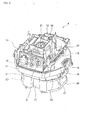
FIG. 2 is an overall perspective view of a main body included in the dust collector. -
FIG. 3 is an exploded perspective view of a filter fixing member, a main body case, and a main body case cover which form the main body. -
FIG. 4 is an overall perspective view of the main body case. -
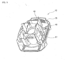
FIG. 5 is an overall perspective view of the main body case cover. -
FIG. 6 is a plan view of the main body case. -
FIG. 7 is a back view of the main body case. -
FIG. 8 is a perspective view of a second opening and closing member capable of opening and closing a communication path formed in the main body case. -
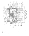
FIG. 9 is a diagram illustrating an operation of catching dust by a pair of filters provided in a tank. -
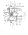
FIG. 10 is a diagram illustrating an operation of cleaning right filters and catching dust by left filters. -
FIG. 11 is a sectional side view of a main part of the main body. -
FIG. 12 is a partial sectional side view of a main body included in a dust collector according to another embodiment. - An embodiment of the present invention will be described with reference to
FIGS. 1 to 11 . As shown inFIGS. 1 to 3 , adust collector 1 includes atraveling base 2, atank 3, and amain body 4. Thetraveling base 2 is molded by using a synthetic resin, and has a circular recess 5 (seeFIG. 1 ) in the upper surface thereof. One front wheel 6 is rotatably provided on a front (the side closer to the viewer inFIG. 1 ) central part of the bottom surface of thetraveling base 2, and a pair ofrear wheels FIG. 1 ) left and right parts of thetraveling base 2. Thedust collector 1 is capable of traveling by the front wheel 6 and therear wheels - The
tank 3 is made of stainless steel, and is formed to have a bottomed cylindrical shape opening in its upper part. Thetank 3 is placed on the upper surface of thetraveling base 2 so as to be fitted in therecess 5. Asuction port 8 is formed in the front surface (the side closer to the viewer inFIG. 1 ) of thetank 3. A dust-collecting hose is connected to thesuction port 8.Hooks tank 3. As shown inFIG. 1 , themain body 4 can be fixed to the upper part of thetank 3 by engaging the ends of thehooks hook engagement portions 19, 19 (seeFIG. 2 ) of amain body case 11 described below. - As shown in
FIG. 3 , themain body 4 has afilter fixing member 10, themain body case 11, and a mainbody case cover 12. Thefilter fixing member 10 is screwed on the lower surface of themain body case 11. As shown inFIGS. 3 and9 , thefilter fixing member 10 is provided with ahollow portion 14 that extends from the central part of thefilter fixing member 10 to the rear part of thefilter fixing member 10, that protrudes downward, and that is closed in the lower part thereof and open in the upper part thereof. Thefilter fixing member 10 is provided, on the right and left sides of thehollow portion 14, withlong holes dust collector 1. Moreover, as shown inFIGS. 2 and3 ,latch members filter fixing member 10. Anelectrode holding plate 17 is screwed on a front part of the lower surface of thefilter fixing member 10 so as to project downward. - As shown in
FIGS. 2 ,3 , and9 ,prefilters filter fixing member 10 so as to communicate with thelong holes main body 4 is fixed to the upper part of thetank 3, theprefilters electrode holding plate 17 project within thetank 3 from the lower surface of thefilter fixing member 10. A pair of water-level detection electrodes (not shown) are held on the back surface of theelectrode holding plate 17 so as to be located at the same position in the vertical direction and with a predetermined interval therebetween in the lateral direction. In the present embodiment, a voltage is applied to the pair of water-level detection electrodes, and when the water-level detection electrodes are electrically connected together via water, it is detected that a certain amount of water has entered thetank 3. The operation of thedust collector 1 is stopped if it is detected that the certain amount of water has entered thetank 3. Theprefilter 20 is a cylindrical body that is made of woven fabric, that has an elliptical shape as viewed in plan, and that is open in the upper part and closed in the lower part. Theprefilter 20 thus can separate thesuction port 8 from themain body 4 within thetank 3. A ring-shaped engagement member 21 (seeFIGS. 2 and3 ) is attached to the peripheral edge of the upper part of theprefilter 20. In the present embodiment, the left andright latch members engagement members prefilters prefilters filter fixing member 10 in a close contact state. Eachprefilter 20 has been subjected to a well-known antistatic treatment using an antistatic agent. - As shown in
FIGS. 3 and9 , apaper filter 22 as a tertiary filter is mounted inside eachprefilter 20 so as to communicate with thelong hole 15. Thisfilter 22 is a cylindrical body that has an elliptical shape as viewed in plan, and that is open in the upper part and closed in the lower part. Thefilter 22 is placed inside theprefilter 20 so that its filter surface faces an inner surface of theprefilter 20. Apolyurethane sponge filter 23 serving as a secondary filter is mounted on the filter surface of thefilter 22 in eachprefilter 20. Since themain body 4 is fixed to the upper part of thetank 3, eachfilter suction port 8 from themain body 4 within eachprefilter 20. Theprefilter 20 and thefilters FIGS. 3 and4 , themain body case 11 includes a bottomedcylindrical portion 25 that is made of a synthetic resin and that is open in its upper part. Thecylindrical portion 25 is provided, protruding downward, at a part of themain body case 11, which is located more toward the front side (the side closer to the viewer inFIGS. 3 and4 ) with respect to the center of themain body case 11. An inlet port 26 (seeFIG. 4 ) is formed in the central portion of the lower surface of thecylindrical portion 25. In the state where thefilter fixing member 10 is fixed to the lower surface of themain body case 11, thecylindrical portion 25 can fit in thehollow portion 14 of thefilter fixing member 10. An electric blower 31 (seeFIGS. 3 and11 ) is fitted in thecylindrical portion 25 in such an attitude that a fan cover 30 (seeFIG. 3 ) covering a fan F (seeFIG. 11 ) faces downward. The fan F is coupled to the tip end of a rotating shaft 35 (seeFIG. 11 ) of a motor, and a plurality of air discharge portions 32 (seeFIGS. 3 and11 ) are provided on the outer peripheral surface of the upper part of thefan cover 30. Thefan cover 30 excluding the upper part thereof is fitted in thecylindrical portion 25, so that theair discharge portions 32 can be placed outside thecylindrical portion 25. When thefan cover 30 is fitted in thecylindrical portion 25, a vent hole H (seeFIG. 11 ) provided in the central portion of the lower surface of thefan cover 30 is placed so as to face theinlet port 26 of thecylindrical portion 25.Reference numeral 27 inFIGS. 3 and11 represents a ring-shaped seal member that seals between the peripheral edge of the lower end of thefan cover 30 and theinlet port 26, andreference numeral 28 represents a sound-absorbing material. - As shown in
FIG. 9 ,intake passages filter fixing member 10. Theintake passages dust collector 1 on the left and right sides of thecylindrical portion 25 fitted in thehollow portion 14, and extend to the rear side of thecylindrical portion 25 to communicate with thehollow portion 14. Theintake passages long holes 15. - As shown in
FIGS. 4 ,6 , and9 , amotor accommodating portion 37 is placed on the upper surface of themain body case 11. Themotor accommodating portion 37 is provided behind thecylindrical portion 25 so as to stand on the upper surface of themain body case 11 and so as to surround a speed reducer cover 40 (seeFIGS. 3 and11 ) attached to aDC motor 36. As shown inFIGS. 6 and7 , acommunication hole 38 that allows themotor accommodating portion 37 to communicate with themain body case 11 is formed in the upper surface of themain body case 11 which corresponds to the bottom surface of themotor accommodating portion 37. TheDC motor 36 is fixed in themotor accommodating portion 37 by tightening screws in screw holes in thespeed reducer cover 40 attached to theDC motor 36 and screw holes 39, 39 (seeFIGS. 4 and6 ) in themotor accommodating portion 37. A cam member 43 (seeFIGS. 9 and11 ) having substantially a reversed L-shape as viewed from the side is coupled to an output shaft 42 (seeFIG. 11 ) of theDC motor 36 through thecommunication hole 38 via a speed reducer 41 (seeFIGS. 3 and11 ) accommodated in thespeed reducer cover 40. In the present embodiment, theDC motor 36 is rotated alternately to the right and left, whereby thecam member 43 can be rotated alternately to the right and left. - As shown in
FIGS. 4 and6 , adischarge passage 44 is provided in the upper surface of themain body case 11. Thedischarge passage 44 is formed by aspace 47 that is surrounded by a wall surface 45 (seeFIG. 4 ) and a rib 46 (seeFIG. 4 ) and is continuous to the opening in the upper surface of thecylindrical portion 25. As described below, air discharged from the air discharge portions 32 (seeFIG. 3 ) located on the downstream side of theelectric blower 31 can be discharged from anoutlet port 48 and outlet windows 49 (seeFIG. 5 ) to the outside of themain body 4 through thedischarge passage 44. - As shown in
FIGS. 4 ,6 , and9 ,communication paths discharge passage 44 are formed on the left and right sides of themotor accommodating portion 37 in the upper surface of themain body case 11. As shown inFIGS. 4 and6 , the upper surface of themain body case 11 is provided withinlet ports communication paths communication paths intake passages 33, 34 (seeFIG. 9 ). This allows thedischarge passage 44 to communicate with theintake passage 33 via thecommunication path 50 and theinlet port 52, and also allows thedischarge passage 44 to communicate with theintake passage 34 via thecommunication path 51 and theinlet port 53. Thehook engagement portions main body case 11. As shown inFIGS. 3 and9 , a ring-shapedseal member 13 is attached to the lower surface of themain body case 11. This allows themain body case 11 to be fixed to thetank 3 in a close contact state. - As shown in
FIGS. 6 ,7 , and9 , a tilted wall 57' is provided in a communication part of theintake passage 33, which is located on the downstream side of theinlet port 52 and which communicates with thehollow portion 14. The tilted wall 57' separates this communication part from thehollow portion 14, and has a vent hole 58'. The tilted wall 57' is formed integrally with a tilted wall formation member 56 (seeFIGS. 3 and7 ) that is attached to the communication part. A plate-like first opening and closing member 55' (seeFIGS. 3 and9 ) capable of opening and closing thevent hole 58 is rotatably supported near the tilted wall 57' on the lower surface of themain body case 11 via a support shaft 60 (seeFIG. 9 ).Reference numeral 54 inFIG. 7 represents a fitting hole in which thesupport shaft 60 is rotatably fitted. In a normal state, as shown inFIG. 9 , the first opening and closing member 55' is biased so as to extend in the vertical direction at a position where the first opening and closingmember 55 opens the vent hole 58'. As shown inFIGS. 6 ,7 , and9 , the tilted wall 57' is tilted such that the upper part thereof is located more toward the first opening and closing member 55' than the lower part thereof in the normal state, and faces the first opening and closing member 55' in the normal state so that a space for air flow 59' (seeFIG. 9 ) is interposed therebetween. The tilted wall 57' is an example of the tilted portion of the present invention. - As shown in
FIGS. 8 and9 , a plate-like second opening and closing member 61' capable of opening and closing theinlet port 52 is provided in theinlet port 52 of thecommunication path 50. The second opening and closing member 61' includes a bar-shapedarm portion 62 extending in the vertical direction with its distal end facing the first opening and closing member 55'. The second opening and closing member 61' is supported in thecommunication path 50 so as to be rotatable about a support shaft 63 (seeFIG. 9 ) supported by the bottom surface of thecommunication path 50. In a normal state, the second opening and closing member 61' is biased to a lateral attitude at a position where the second opening and closingmember 61 closes theinlet port 52 by its own weight. - As in the communication part of the
intake passage 33 which communicates with thehollow portion 14, a tiltedwall 57 having avent hole 58 is provided in a communication part of theintake passage 34, which is located on the downstream side of theinlet port 53 and which communicates with thehollow portion 14. A first opening and closingmember 55 capable of opening and closing thevent hole 58 is provided near the tiltedwall 57. As in theinlet port 52 of thecommunication path 50, a second opening and closingmember 61 capable of opening and closing theinlet port 53 is provided in theinlet port 53 of thecommunication path 51 shown inFIGS. 6 and9 . The tiltedwall 57 is also an example of the tilted portion of the present invention. - As a characteristic configuration of the present embodiment, in order to suppress an increase in longitudinal dimension of the
dust collector 1, the pair ofprefilters DC motor 36 in thetank 3 shown inFIG. 9 so as to face each other with an interval therebetween in the lateral direction. In addition, each of the first opening andclosing members 55, 55' is placed between theprefilter 20 and theDC motor 36 in the lateral direction of thedust collector 1. - The main body case cover 12 shown in
FIGS. 1 to 3 , and5 is made of a synthetic resin, and closes the opening in the upper surface of themain body case 11. The main body case cover 12 has a bodycover accommodating portion 67 that is open in its upper part. The bodycover accommodating portion 67 is provided, protruding upward, at a part of the mainbody case cover 12, which is located more toward the front side with respect to the center of the mainbody case cover 12. In the state where the main body case cover 12 is fixed to the upper part of themain body case 11 by tightening screws in the main body case cover 12 and themain body case 11, the bodycover accommodating portion 67 vertically accommodates a body cover 72 (seeFIG. 3 ) accommodating the motor of theelectric blower 31, etc. As shown inFIG. 5 , theoutlet port 48 is formed in the upper surface of the mainbody case cover 12. Theoutlet port 48 allows the upper surface of the main body case cover 12 to communicate with the opening in the upper surface of themain body case 11. The plurality ofoutlet windows 49 are formed in awall surface 75 located on the rear side of the mainbody case cover 12. Anoperation portion 76 is provided on the front surface of the mainbody case cover 12. Various switches such as an operation switch S and an outlet for power supply to external equipment are placed in theoperation portion 76. InFIG. 3 ,reference numeral 77 represents a controller, andreference numeral 78 represents a sound-absorbing material. Thecontroller 77 and the sound-absorbingmaterial 78 are accommodated in the mainbody case cover 12. - Operation of the
dust collector 1 will be described below. In response to turning-on of the operation switch S (seeFIG. 1 ) provided in the main body 4 (seeFIG. 1 ) of thedust collector 1, the motor of theelectric blower 31 shown inFIG. 3 is driven to rotate the fan F (seeFIG. 11 ) in thefan cover 30. Then, air containing dust is drawn into thetank 3 through the suction port 8 (seeFIG. 1 ) from outside via the dust-collecting hose, and this air flows through theprefilters filters filters FIG. 9 , and into theintake passages long holes 15. At this time, part of the dust is caught by theprefilters prefilters filters filters - Then, the air that has flown into the
intake passage 33 flows through the vent hole 58' of the tilted wall 57' and the space for air flow 59' into thehollow portion 14 of thefilter fixing member 10. Then, the air flows through the vent hole H (seeFIG. 11 ) of thefan cover 30 from the inlet port 26 (seeFIG. 11 ) of themain body case 11, and is guided into thefan cover 30. Similarly, the air that has flown into theintake passage 34 flows through thevent hole 58 of the tiltedwall 57 and the space forair flow 59 into thehollow portion 14 of thefilter fixing member 10. Then, the air flows through the vent hole H (seeFIG. 11 ) of thefan cover 30 from the inlet port 26 (seeFIG. 11 ) of themain body case 11, and is guided into thefan cover 30. As described above, in thedust collector 1, theprefilters filters filters suction port 8 to the vent hole H of thefan cover 30 on the upstream side of theelectric blower 31, and the pair of intake paths are combined together near the vent hole H of thefan cover 30. The air guided into thefan cover 30 is discharged into thedischarge passage 44 shown inFIG. 4 from the air discharge portions 32 (seeFIGS. 3 and11 ). Then, the air flows through the outlet port 48 (seeFIG. 5 ) from thedischarge passage 44, and is discharged to the outside of themain body 4 from the outlet windows 49 (seeFIG. 5 ). - The dust caught by the
prefilter 20 and thefilters prefilter 20 and thefilters dust collector 1. During the dust collecting operation of catching dust by theprefilters filters filters FIG. 9 , thecam member 43 rotates rightward and contacts the first opening and closingmember 55 of theintake passage 34 in response to rotation of theoutput shaft 42 of theDC motor 36, as shown inFIG. 10 . Thus, the first opening and closingmember 55 is pressed by thecam member 43 toward the tiltedwall 57 of theintake passage 34, and contacts the tiltedwall 57 so as to close thevent hole 58 and to eliminate the space for air flow, thereby performing the operation of closing theintake passage 34. In this manner, the first opening and closingmember 55 closes one of the intake paths, which extends from thesuction port 8 to thefan cover 30 through theintake passage 34. At this time, thearm portion 62 is pressed in a direction away from the tiltedwall 57 by the first opening and closingmember 55. Thus, the second opening and closingmember 61 rotates in response to the operation of closing theintake passage 34 by the first opening and closingmember 55. As a result, as shown inFIG. 10 , the second opening and closingmember 61 opens theinlet port 53 of thecommunication path 51. - In the state where the operation of closing the
intake passage 34 is performed and theinlet port 53 is opened as shown inFIG. 10 , thetank 3 and themain body case 11 has a negative pressure. Accordingly, the discharged air that has passed through thedischarge passage 44 is guided from theinlet port 53 into theintake passage 34 as shown by two-dot chain arrow inFIG. 4 . The discharged air in theintake passage 34 flows backward from the downstream side to the upstream side in theintake passage 34, and into theright filter 22 through thelong hole 15. Then, the discharged air sequentially flows through theright filter 22, theright filter 23, and theright prefilter 20, and returns to thetank 3. At this time, the discharged air flowing backward can blow away the dust caught by thefilters dust collector 1, theright prefilter 20 and theright filters left prefilter 20 and the left filters 23, 22. In addition, since the right and leftprefilters prefilter 20 can be suppressed. As a result, a dust separation property is improved. - The discharged air that is returned to the
tank 3 through theright filters right prefilter 20 flows into theintake passage 33 through thelong hole 15 after flowing through theleft prefilter 20 and the left filters 23, 23. Thus, the discharged air flows into the other intake path extending from thesuction port 8 to thefan cover 30 via theintake passage 33. - On the other hand, if the
cam member 43 rotates leftward and contacts the first opening and closing member 55' of theintake passage 33 during the dust collecting operation, the first opening and closing member 55' and the second opening and closing member 61' operate in a manner similar to that in the above example in which thecam member 43 rotates rightward. Thus, the discharged air that has passed through thedischarge passage 44 is guided into theintake passage 33 through the inlet port 52 (seeFIG. 4 ). At this time, the first opening and closingmember 55 contacting the tiltedwall 57 of theintake passage 34 is restored to the position where thevent hole 58 is opened as shown inFIG. 9 . Thus, dust can be caught by theright prefilter 20 and theright filters intake passage 33 flows backward from the downstream side to the upstream side in theintake passage 33. Thus, the discharged air sequentially flows through the left filters 22, 23 and theleft prefilter 20, and returns to thetank 3. At this time, the discharged air flowing backward can blow away the dust caught by thefilters left prefilter 20 and the left filters 23, 22 can be cleaned while catching dust by theright prefilter 20 and theright filters dust collector 1, thecam member 43 rotates alternately to the right and left, whereby thecam member 43 alternately contacts the first opening and closing member 55' capable of opening and closing the vent hole 58' of theintake passage 33 and the first opening and closingmember 55 capable of opening and closing thevent hole 58 of theintake passage 34. Thus, the operation of closing theintake passage 33 and the operation of closing theintake passage 34 can be alternately performed. TheDC motor 36 and thecam member 43 are an example of the operation unit of the present invention. - The
dust collector 1 of the present embodiment uses theDC motor 36 and thecam member 43 to alternately perform the operation of closing theintake passage 33 and the operation of closing theintake passage 34 by the first opening and closing member 55' capable of opening and closing the vent hole 58' of theintake passage 33 and the first opening and closingmember 55 capable of opening and closing thevent hole 58 of theintake passage 34. Thus, cleaning of the left filters 20, 23, 22 and cleaning of theright filters right filters dust collector 1 as well. Moreover, since theDC motor 36 and thecam member 43 are used to operate the first opening andclosing members 55, 55' and the second opening andclosing members 61, 61', electric control is not required to operate the opening and closing members 55 (55'), 61 (61'), whereby the structure of thedust collector 1 is simplified. - Since the operation of closing the
intake passage 33 and the operation of closing theintake passage 34 can be alternately performed by oneDC motor 36 and onecam member 43 coupled to theoutput shaft 42 of theDC motor 36 via thespeed reducer 41, the number ofDC motors 36 and the number ofcam members 43 can be minimized. This can suppress manufacturing cost of thedust collector 1. - The pair of
filters DC motor 36 and the first opening andclosing members 55, 55', and so as to suppress an increase in longitudinal dimension of thedust collector 1. - Moreover, since each
prefilter 20 has been subjected to an antistatic treatment, accumulation of static electricity on theprefilter 20 can be suppressed. This suppresses electrostatic attraction of dust to theprefilter 20, whereby satisfactory dust separation from theprefilter 20 can be achieved. - Furthermore, in a normal state of the first opening and closing member 55', the vent hole 58' of the tilted wall 57' provided on the downstream side of the
inlet port 52 in theintake passage 33 is opened. Similarly, in a normal state of the first opening and closingmember 55, thevent hole 58 of the tiltedwall 57 provided on the downstream side of theinlet port 53 in theintake passage 34 is opened. Accordingly, theintake passages closing members 55', 55 perform the operation of closing theintake passages vent hole 58', 58 are closed and the spaces for air flow is eliminated, whereby eachintake passage - The present invention is not limited to the above embodiment, and the configuration can be partially modified as appropriate without departing from the scope of the invention. For example, in the case where the DC motor and the cam member which operate the first opening and closing
member 55 of theintake passage 33 are provided separately from the DC motor and the cam member which operate the first opening and closingmember 55 of theintake passage 34, and the operation of closing theintake passage 33 is performed by one of the DC motors and one of the cam members, the first opening and closingmember 55 of theintake passage 34 may be biased by the other DC motor and the other cam member to the position where thevent hole 58 is closed. In addition to theprefilter 20, thepaper filter 22 may be subjected to an antistatic treatment. Unlike the above embodiment, the second opening and closing member may be provided so as to be connected to the first opening and closing member, and the second opening and closing member may open the inlet port of the communication path in response to the operation of closing the first opening and closing member. Unlike the above embodiment, thecam member 43 shown inFIG. 12 may be directly coupled to theoutput shaft 42 of theDC motor 36 having high toque characteristics. In this case, for example, by rotating theoutput shaft 42 of theDC motor 36, thecam member 43 is rotated leftward to bring the first opening and closingmember 55 into contact with the tiltedwall 57 of the intake passage, and then current application to theDC motor 36 is stopped. In this case, the first opening and closingmember 55 can press thecam member 43 back in the direction away from the tiltedwall 57 due to the pressure of the discharged air in the intake passage. Accordingly, unlike the above embodiment, thecam member 43 rotated leftward need not be controlled to rotate rightward by theDC motor 36 in order to open thevent hole 58 of the intake passage. - It is explicitly stated that all features disclosed in the description and/or the claims are intended to be disclosed separately and independently from each other for the purpose of original disclosure as well as for the purpose of restricting the claimed invention independent of the composition of the features in the embodiments and/or the claims. It is explicitly stated that all value ranges or indications of groups of entities disclose every possible intermediate value or intermediate entity for the purpose of original disclosure as well as for the purpose of restricting the claimed invention, in particular as limits of value ranges.
Claims (12)
- A dust collector (1), in which a main body (4) including an electric blower (31) is provided in an upper part of a tank (3) having a suction port (8), air that is drawn through the suction port (8) from outside by the electric blower (31) is discharged through the tank (3) and the main body (4), and a filter (20, 22, 23) that separates the intake port (8) from the main body (4) in an intake path extending from the suction port (8) to the electric blower (31) and that is capable of catching dust in the outside air is provided in the tank (3), the dust collector (1) characterized in that
a pair of the intake paths in which air flows respectively through a pair of the filters (20, 22, 23) projecting within the tank (3) are formed so as to be combined together on an upstream side of the electric blower (31),
a pair of communication paths (50, 51) are formed so as to allow a discharge passage (44) on a downstream side of the electric blower (31) to communicate with each of the intake paths,
first opening and closing members (55, 55') are each provided on a downstream side of the communication path (50, 51) in the intake path, are capable of opening and closing the intake path, and are biased, in a normal state, to a position where the first opening and closing member opens the intake path,
second opening and closing members (61, 61') are each provided in the communication path (50, 51), are capable of opening and closing the communication path (50, 51), are biased, in the normal state, to a position where the second opening and closing member (61, 61') closes the communication path (50, 51), and open the communication path (50, 51) in response to a closing operation of closing the intake path by the first opening and closing member (55, 55'), and
an operation unit is provided that is capable of alternately causing the first opening and closing members (55, 55') in the intake paths to perform the closing operation, wherein
when the operation unit causes one of the first opening and closing members (55, 55') to perform the closing operation and thus causes the second opening and closing member (61, 61') to open the communication path (50, 51), discharged air in the discharge passage (44) is guided to one of the intake paths via the communication path (50, 51), the discharged air is caused to flow backward in the intake path and returned to the tank (3) through the filter (20, 22, 23), and is guided to the other intake path, so that the dust on the filter (20, 22, 23) of the one intake path is removed. - The dust collector (1) according to claim 1, wherein
the operation unit includes a motor (36) placed between the pair of first opening and closing members (55, 55'), and a cam member (43) provided on an output shaft (42) of the motor (36) and formed to alternately contact the first opening and closing members (55, 55') respectively in response to rotation of the output shaft (42) so that the first opening and closing member (55, 55') performs the closing operation. - The dust collector (1) according to claim 2, wherein
the filters (20, 22, 23) through which air flows in the pair of intake paths are placed outside the motor (36) so as to face each other with an interval therebetween, and each of the first opening and closing members (55, 55') is placed between each of the filters (20, 22, 23) and the motor (36). - The dust collector (1) according to any one of claims 1 to 4, wherein
a tilted portion (57, 57') having a vent hole (58, 58') is provided on the downstream side of the communication path (50, 51) in the intake path so as to face the first opening and closing member (55, 55') in the normal state with a space for air flow (59, 59') therebetween, and the first opening and closing member (55, 55') performing the closing operation is capable of contacting the tilted portion (57, 57') in a state where the vent hole (58, 58') is closed and the ventilation interval (59, 59') is eliminated. - The dust collector (1) according to claim 4, wherein
the first opening and closing member (55, 55') is supported by a support shaft near the tilted portion (57, 57') in the intake path so as to be rotatable in a direction toward and away from the tilted portion (57, 57') via the support shaft (60), and
when the cam member (43) contacts the first opening and closing member (55, 55'), the first opening and closing member (55, 55') rotates in the direction toward the tilted portion (57, 57'), and thus performs the closing operation and contacts the tilted portion (57, 57'). - The dust collector (1) according to claim 4 or 5, wherein
an inlet port (52, 53) that allows the discharge passage (44) to communicate with the intake path is formed in the communication path (50, 51), and in the normal state, the second opening and closing member (61, 61') is biased to a position where the second opening and closing member (61,61') closes the inlet port (52, 53),
the second opening and closing member (61, 61') includes a bar-shaped arm portion (62) having a distal end thereof facing the first opening and closing member (55, 55'), and a support shaft (63) for supporting the second opening and closing member (61, 61') in the communication path (50) so that the second opening and closing member (61, 61') is rotatable in a direction toward and away from the inlet port (52, 53), and
the first opening and closing member (55, 55') that rotates in a direction toward the tilted portion (57, 57') presses the second opening and closing member (66) through the arm portion (62), whereby the second opening and closing member (61, 61') rotates in the direction away from the inlet port (52, 53) to open the inlet port (52, 53). - The dust collector (1) according to any one of claims 1 to 6, wherein
the filter (20, 22, 23) includes a primary filter (20) capable of catching the dust and having been subjected to an antistatic treatment. - The dust collector (1) according to claim 7, wherein
the primary filter (20) is formed as a cylindrical body, a tertiary filter (22) as a cylindrical body is mounted inside the primary filter (20) so that a filter surface of the tertiary filter (22) faces an inner surface of the primary filter (20), and a secondary filter (23) is mounted on the filter surface of the tertiary filter (22). - The dust collector (1) according to claim 8, wherein
the primary filter (20) is made of woven fabric, the secondary filter (23) is made of polyurethane sponge, and the tertiary filter (22) is made of paper. - The dust collector (1) according to claim 8 or 9, wherein
the main body (4) has a filter fixing member (10), a latch member (16) capable of swinging via a support shaft is attached to a side surface of the filter fixing member (10), and an engagement member (21) with which the latch member (16) is engaged is attached to a peripheral edge of an upper part of the primary filter (20). - The dust collector (1) according to any one of claims 1 to 10, further comprising:a traveling base (2) having a recess (5) in an upper surface thereof and having a wheel (6, 7) rotatably provided on a bottom surface thereof, whereinthe tank (3) is placed on the traveling base (2) so as to be fitted in the recess (5).
- The dust collector (1) according to any one of claims 1 to 11, wherein
a hook (9) is attached to an outer side surface of the tank (3), and a hook engagement portion (19) that engages with the hook (9) is provided in the main body (4).
Applications Claiming Priority (1)
| Application Number | Priority Date | Filing Date | Title |
|---|---|---|---|
| JP2011278506A JP5954981B2 (en) | 2011-12-20 | 2011-12-20 | Dust collector |
Publications (3)
| Publication Number | Publication Date |
|---|---|
| EP2606796A2 true EP2606796A2 (en) | 2013-06-26 |
| EP2606796A3 EP2606796A3 (en) | 2015-12-09 |
| EP2606796B1 EP2606796B1 (en) | 2019-10-09 |
Family
ID=47278119
Family Applications (1)
| Application Number | Title | Priority Date | Filing Date |
|---|---|---|---|
| EP12193026.7A Active EP2606796B1 (en) | 2011-12-20 | 2012-11-16 | Dust collector |
Country Status (5)
| Country | Link |
|---|---|
| US (1) | US8940064B2 (en) |
| EP (1) | EP2606796B1 (en) |
| JP (1) | JP5954981B2 (en) |
| CN (1) | CN103170194B (en) |
| RU (1) | RU2012155281A (en) |
Cited By (2)
| Publication number | Priority date | Publication date | Assignee | Title |
|---|---|---|---|---|
| US10729299B2 (en) | 2016-01-19 | 2020-08-04 | Festool Gmbh | Suction device |
| US11627863B2 (en) | 2017-01-13 | 2023-04-18 | Black & Decker Inc. | Dust collection box |
Families Citing this family (11)
| Publication number | Priority date | Publication date | Assignee | Title |
|---|---|---|---|---|
| JP6150517B2 (en) * | 2012-12-25 | 2017-06-21 | 株式会社マキタ | Dust collector |
| JP6161284B2 (en) * | 2012-12-25 | 2017-07-12 | 株式会社マキタ | Dust collector |
| CN103438057A (en) * | 2013-09-09 | 2013-12-11 | 苏州上洋机电科技有限公司 | Stamping connection piece |
| EP2908067B1 (en) * | 2014-02-18 | 2022-04-13 | Blueair AB | Air purifier device with coupling mechanism |
| CN105327564B (en) * | 2015-11-12 | 2018-02-06 | 中山市迪米尔机电设备有限公司 | Main unit of central dust collecting system |
| CN110115884A (en) * | 2019-04-23 | 2019-08-13 | 广州航海学院 | Haze purifier and its operating method |
| EP3753464A1 (en) | 2019-06-18 | 2020-12-23 | Hilti Aktiengesellschaft | Arrangement of a cleaning unit in a vacuum cleaner and vacuum cleaner comprising such an arrangement |
| US20220211234A1 (en) * | 2020-03-18 | 2022-07-07 | Suzhou Alton Electrical & Mechanical Industry Co., Ltd. | Vacuum cleaner |
| WO2022109107A1 (en) | 2020-11-19 | 2022-05-27 | Milwaukee Electric Tool Corporation | Portable dust extractor |
| CN114869168A (en) * | 2021-02-05 | 2022-08-09 | 苏州欧圣电气股份有限公司 | Dust collector |
| DE102023123077A1 (en) * | 2023-08-28 | 2025-03-06 | Electrostar Gmbh | Switching device for a vacuum cleaner and vacuum cleaner |
Citations (1)
| Publication number | Priority date | Publication date | Assignee | Title |
|---|---|---|---|---|
| JP3457929B2 (en) | 2000-07-13 | 2003-10-20 | 日本クリーナー販売株式会社 | Cleaning equipment |
Family Cites Families (12)
| Publication number | Priority date | Publication date | Assignee | Title |
|---|---|---|---|---|
| US4204849A (en) * | 1978-08-30 | 1980-05-27 | Donaldson Company, Inc. | Discharge valve assembly for multiple-stage dust collector |
| JPH023772Y2 (en) * | 1984-11-05 | 1990-01-29 | ||
| CA2192882C (en) * | 1996-01-23 | 2002-04-16 | Shigenori Hato | Suction tool for an electric vacuum cleaner |
| US5905752A (en) * | 1996-07-15 | 1999-05-18 | Amsted Industries Incorporated | ARC furnace fume collection system and method |
| CN2364956Y (en) * | 1999-01-04 | 2000-02-23 | 董新宇 | Cement silo top bag filter |
| DE10101219C9 (en) * | 2001-01-12 | 2018-05-17 | Nilfisk-Advance A/S | A vacuum cleaner |
| US7082640B2 (en) * | 2003-07-18 | 2006-08-01 | Christy, Inc. | Ambient air backflushed filter vacuum |
| CN2757218Y (en) * | 2004-12-25 | 2006-02-08 | 富准精密工业(深圳)有限公司 | Computer ssytem air guide device |
| ITMI20071121A1 (en) * | 2007-06-01 | 2008-12-02 | Guido Valentini | "DUST ASPIRATOR WITH AUTOMATIC FILTER CLEANING" |
| JP2010035848A (en) * | 2008-08-06 | 2010-02-18 | Toshiba Corp | Vacuum cleaner |
| DE102008047047B4 (en) * | 2008-09-13 | 2012-09-20 | Alto Deutschland Gmbh | Filter cleaning in a vacuum cleaner with flap element |
| JP5197678B2 (en) * | 2010-06-07 | 2013-05-15 | 株式会社マキタ | Dust collector |
-
2011
- 2011-12-20 JP JP2011278506A patent/JP5954981B2/en active Active
-
2012
- 2012-09-17 CN CN201210345022.2A patent/CN103170194B/en active Active
- 2012-11-15 US US13/677,886 patent/US8940064B2/en active Active
- 2012-11-16 EP EP12193026.7A patent/EP2606796B1/en active Active
- 2012-12-19 RU RU2012155281/12A patent/RU2012155281A/en not_active Application Discontinuation
Patent Citations (1)
| Publication number | Priority date | Publication date | Assignee | Title |
|---|---|---|---|---|
| JP3457929B2 (en) | 2000-07-13 | 2003-10-20 | 日本クリーナー販売株式会社 | Cleaning equipment |
Cited By (2)
| Publication number | Priority date | Publication date | Assignee | Title |
|---|---|---|---|---|
| US10729299B2 (en) | 2016-01-19 | 2020-08-04 | Festool Gmbh | Suction device |
| US11627863B2 (en) | 2017-01-13 | 2023-04-18 | Black & Decker Inc. | Dust collection box |
Also Published As
| Publication number | Publication date |
|---|---|
| JP2013128565A (en) | 2013-07-04 |
| CN103170194B (en) | 2015-01-28 |
| US20130152519A1 (en) | 2013-06-20 |
| US8940064B2 (en) | 2015-01-27 |
| CN103170194A (en) | 2013-06-26 |
| EP2606796B1 (en) | 2019-10-09 |
| RU2012155281A (en) | 2014-06-27 |
| EP2606796A3 (en) | 2015-12-09 |
| JP5954981B2 (en) | 2016-07-20 |
Similar Documents
| Publication | Publication Date | Title |
|---|---|---|
| EP2606796B1 (en) | Dust collector | |
| EP4154786A1 (en) | Cleaning device comprising vacuum cleaner and docking station | |
| JP5810215B2 (en) | Electric vacuum cleaner with pressure cleaner for filter cleaning | |
| CN111432704B (en) | Robot Cleaner | |
| KR101536542B1 (en) | Cleaning robot | |
| CN106102536B (en) | Method and vacuuming device for cleaning a filter of a vacuuming device | |
| EP3082539B1 (en) | Dust container | |
| CN223248090U (en) | Vacuum cleaner system | |
| KR20180016090A (en) | Humidification type air cleaner | |
| CN113171027A (en) | Cleaning device, dust box assembly, control method and control system | |
| JP2017109091A (en) | Suction cleaner and operation method of suction cleaner | |
| EP2211678A1 (en) | Electric vacuum cleaner | |
| CN114947645A (en) | Surface cleaning apparatus | |
| JP5798048B2 (en) | Electric vacuum cleaner | |
| CN214906373U (en) | Suction body and electric vacuum cleaner | |
| JP5815147B2 (en) | Self-propelled vacuum cleaner | |
| JP2012219703A (en) | Vehicular air cleaner | |
| TWI482607B (en) | Cleaning robots | |
| JP2017056399A (en) | Dust collector | |
| JP6106251B2 (en) | Self-propelled vacuum cleaner | |
| CN101596085B (en) | Exhaust gas filter of dust collector | |
| CN215383696U (en) | A vacuuming base station, cleaning robot and cleaning system | |
| CN116428679A (en) | Air supply device | |
| CN111503745A (en) | air conditioner | |
| CN213464919U (en) | Magnetic suction type dust box, integrated dust box water tank and cleaning robot |
Legal Events
| Date | Code | Title | Description |
|---|---|---|---|
| AK | Designated contracting states |
Kind code of ref document: A2 Designated state(s): AL AT BE BG CH CY CZ DE DK EE ES FI FR GB GR HR HU IE IS IT LI LT LU LV MC MK MT NL NO PL PT RO RS SE SI SK SM TR |
|
| AX | Request for extension of the european patent |
Extension state: BA ME |
|
| PUAI | Public reference made under article 153(3) epc to a published international application that has entered the european phase |
Free format text: ORIGINAL CODE: 0009012 |
|
| PUAL | Search report despatched |
Free format text: ORIGINAL CODE: 0009013 |
|
| AK | Designated contracting states |
Kind code of ref document: A3 Designated state(s): AL AT BE BG CH CY CZ DE DK EE ES FI FR GB GR HR HU IE IS IT LI LT LU LV MC MK MT NL NO PL PT RO RS SE SI SK SM TR |
|
| AX | Request for extension of the european patent |
Extension state: BA ME |
|
| RIC1 | Information provided on ipc code assigned before grant |
Ipc: A47L 5/28 20060101AFI20151104BHEP Ipc: A47L 9/20 20060101ALI20151104BHEP |
|
| 17P | Request for examination filed |
Effective date: 20160603 |
|
| RBV | Designated contracting states (corrected) |
Designated state(s): AL AT BE BG CH CY CZ DE DK EE ES FI FR GB GR HR HU IE IS IT LI LT LU LV MC MK MT NL NO PL PT RO RS SE SI SK SM TR |
|
| RIN1 | Information on inventor provided before grant (corrected) |
Inventor name: TAHARA, TAKAYUKI Inventor name: HARA, RYOSUKE |
|
| GRAP | Despatch of communication of intention to grant a patent |
Free format text: ORIGINAL CODE: EPIDOSNIGR1 |
|
| STAA | Information on the status of an ep patent application or granted ep patent |
Free format text: STATUS: GRANT OF PATENT IS INTENDED |
|
| INTG | Intention to grant announced |
Effective date: 20190523 |
|
| GRAS | Grant fee paid |
Free format text: ORIGINAL CODE: EPIDOSNIGR3 |
|
| GRAA | (expected) grant |
Free format text: ORIGINAL CODE: 0009210 |
|
| STAA | Information on the status of an ep patent application or granted ep patent |
Free format text: STATUS: THE PATENT HAS BEEN GRANTED |
|
| RIN1 | Information on inventor provided before grant (corrected) |
Inventor name: TAHARA, TAKAYUKI Inventor name: HARA, RYOSUKE |
|
| AK | Designated contracting states |
Kind code of ref document: B1 Designated state(s): AL AT BE BG CH CY CZ DE DK EE ES FI FR GB GR HR HU IE IS IT LI LT LU LV MC MK MT NL NO PL PT RO RS SE SI SK SM TR |
|
| RAP1 | Party data changed (applicant data changed or rights of an application transferred) |
Owner name: MAKITA CORPORATION |
|
| REG | Reference to a national code |
Ref country code: GB Ref legal event code: FG4D |
|
| REG | Reference to a national code |
Ref country code: CH Ref legal event code: EP |
|
| REG | Reference to a national code |
Ref country code: IE Ref legal event code: FG4D |
|
| REG | Reference to a national code |
Ref country code: DE Ref legal event code: R096 Ref document number: 602012064696 Country of ref document: DE |
|
| REG | Reference to a national code |
Ref country code: AT Ref legal event code: REF Ref document number: 1187819 Country of ref document: AT Kind code of ref document: T Effective date: 20191115 |
|
| REG | Reference to a national code |
Ref country code: NL Ref legal event code: MP Effective date: 20191009 |
|
| REG | Reference to a national code |
Ref country code: LT Ref legal event code: MG4D |
|
| REG | Reference to a national code |
Ref country code: AT Ref legal event code: MK05 Ref document number: 1187819 Country of ref document: AT Kind code of ref document: T Effective date: 20191009 |
|
| PG25 | Lapsed in a contracting state [announced via postgrant information from national office to epo] |
Ref country code: GR Free format text: LAPSE BECAUSE OF FAILURE TO SUBMIT A TRANSLATION OF THE DESCRIPTION OR TO PAY THE FEE WITHIN THE PRESCRIBED TIME-LIMIT Effective date: 20200110 Ref country code: LV Free format text: LAPSE BECAUSE OF FAILURE TO SUBMIT A TRANSLATION OF THE DESCRIPTION OR TO PAY THE FEE WITHIN THE PRESCRIBED TIME-LIMIT Effective date: 20191009 Ref country code: SE Free format text: LAPSE BECAUSE OF FAILURE TO SUBMIT A TRANSLATION OF THE DESCRIPTION OR TO PAY THE FEE WITHIN THE PRESCRIBED TIME-LIMIT Effective date: 20191009 Ref country code: BG Free format text: LAPSE BECAUSE OF FAILURE TO SUBMIT A TRANSLATION OF THE DESCRIPTION OR TO PAY THE FEE WITHIN THE PRESCRIBED TIME-LIMIT Effective date: 20200109 Ref country code: FI Free format text: LAPSE BECAUSE OF FAILURE TO SUBMIT A TRANSLATION OF THE DESCRIPTION OR TO PAY THE FEE WITHIN THE PRESCRIBED TIME-LIMIT Effective date: 20191009 Ref country code: PL Free format text: LAPSE BECAUSE OF FAILURE TO SUBMIT A TRANSLATION OF THE DESCRIPTION OR TO PAY THE FEE WITHIN THE PRESCRIBED TIME-LIMIT Effective date: 20191009 Ref country code: AT Free format text: LAPSE BECAUSE OF FAILURE TO SUBMIT A TRANSLATION OF THE DESCRIPTION OR TO PAY THE FEE WITHIN THE PRESCRIBED TIME-LIMIT Effective date: 20191009 Ref country code: NO Free format text: LAPSE BECAUSE OF FAILURE TO SUBMIT A TRANSLATION OF THE DESCRIPTION OR TO PAY THE FEE WITHIN THE PRESCRIBED TIME-LIMIT Effective date: 20200109 Ref country code: NL Free format text: LAPSE BECAUSE OF FAILURE TO SUBMIT A TRANSLATION OF THE DESCRIPTION OR TO PAY THE FEE WITHIN THE PRESCRIBED TIME-LIMIT Effective date: 20191009 Ref country code: PT Free format text: LAPSE BECAUSE OF FAILURE TO SUBMIT A TRANSLATION OF THE DESCRIPTION OR TO PAY THE FEE WITHIN THE PRESCRIBED TIME-LIMIT Effective date: 20200210 Ref country code: LT Free format text: LAPSE BECAUSE OF FAILURE TO SUBMIT A TRANSLATION OF THE DESCRIPTION OR TO PAY THE FEE WITHIN THE PRESCRIBED TIME-LIMIT Effective date: 20191009 Ref country code: ES Free format text: LAPSE BECAUSE OF FAILURE TO SUBMIT A TRANSLATION OF THE DESCRIPTION OR TO PAY THE FEE WITHIN THE PRESCRIBED TIME-LIMIT Effective date: 20191009 |
|
| PG25 | Lapsed in a contracting state [announced via postgrant information from national office to epo] |
Ref country code: HR Free format text: LAPSE BECAUSE OF FAILURE TO SUBMIT A TRANSLATION OF THE DESCRIPTION OR TO PAY THE FEE WITHIN THE PRESCRIBED TIME-LIMIT Effective date: 20191009 Ref country code: IS Free format text: LAPSE BECAUSE OF FAILURE TO SUBMIT A TRANSLATION OF THE DESCRIPTION OR TO PAY THE FEE WITHIN THE PRESCRIBED TIME-LIMIT Effective date: 20200224 Ref country code: RS Free format text: LAPSE BECAUSE OF FAILURE TO SUBMIT A TRANSLATION OF THE DESCRIPTION OR TO PAY THE FEE WITHIN THE PRESCRIBED TIME-LIMIT Effective date: 20191009 |
|
| PG25 | Lapsed in a contracting state [announced via postgrant information from national office to epo] |
Ref country code: AL Free format text: LAPSE BECAUSE OF FAILURE TO SUBMIT A TRANSLATION OF THE DESCRIPTION OR TO PAY THE FEE WITHIN THE PRESCRIBED TIME-LIMIT Effective date: 20191009 |
|
| REG | Reference to a national code |
Ref country code: CH Ref legal event code: PL |
|
| REG | Reference to a national code |
Ref country code: DE Ref legal event code: R097 Ref document number: 602012064696 Country of ref document: DE |
|
| PG2D | Information on lapse in contracting state deleted |
Ref country code: IS |
|
| PG25 | Lapsed in a contracting state [announced via postgrant information from national office to epo] |
Ref country code: CH Free format text: LAPSE BECAUSE OF NON-PAYMENT OF DUE FEES Effective date: 20191130 Ref country code: EE Free format text: LAPSE BECAUSE OF FAILURE TO SUBMIT A TRANSLATION OF THE DESCRIPTION OR TO PAY THE FEE WITHIN THE PRESCRIBED TIME-LIMIT Effective date: 20191009 Ref country code: LI Free format text: LAPSE BECAUSE OF NON-PAYMENT OF DUE FEES Effective date: 20191130 Ref country code: LU Free format text: LAPSE BECAUSE OF NON-PAYMENT OF DUE FEES Effective date: 20191116 Ref country code: CZ Free format text: LAPSE BECAUSE OF FAILURE TO SUBMIT A TRANSLATION OF THE DESCRIPTION OR TO PAY THE FEE WITHIN THE PRESCRIBED TIME-LIMIT Effective date: 20191009 Ref country code: RO Free format text: LAPSE BECAUSE OF FAILURE TO SUBMIT A TRANSLATION OF THE DESCRIPTION OR TO PAY THE FEE WITHIN THE PRESCRIBED TIME-LIMIT Effective date: 20191009 Ref country code: DK Free format text: LAPSE BECAUSE OF FAILURE TO SUBMIT A TRANSLATION OF THE DESCRIPTION OR TO PAY THE FEE WITHIN THE PRESCRIBED TIME-LIMIT Effective date: 20191009 Ref country code: MC Free format text: LAPSE BECAUSE OF FAILURE TO SUBMIT A TRANSLATION OF THE DESCRIPTION OR TO PAY THE FEE WITHIN THE PRESCRIBED TIME-LIMIT Effective date: 20191009 Ref country code: IS Free format text: LAPSE BECAUSE OF FAILURE TO SUBMIT A TRANSLATION OF THE DESCRIPTION OR TO PAY THE FEE WITHIN THE PRESCRIBED TIME-LIMIT Effective date: 20200209 |
|
| PLBE | No opposition filed within time limit |
Free format text: ORIGINAL CODE: 0009261 |
|
| STAA | Information on the status of an ep patent application or granted ep patent |
Free format text: STATUS: NO OPPOSITION FILED WITHIN TIME LIMIT |
|
| REG | Reference to a national code |
Ref country code: BE Ref legal event code: MM Effective date: 20191130 |
|
| PG25 | Lapsed in a contracting state [announced via postgrant information from national office to epo] |
Ref country code: SM Free format text: LAPSE BECAUSE OF FAILURE TO SUBMIT A TRANSLATION OF THE DESCRIPTION OR TO PAY THE FEE WITHIN THE PRESCRIBED TIME-LIMIT Effective date: 20191009 Ref country code: IT Free format text: LAPSE BECAUSE OF FAILURE TO SUBMIT A TRANSLATION OF THE DESCRIPTION OR TO PAY THE FEE WITHIN THE PRESCRIBED TIME-LIMIT Effective date: 20191009 Ref country code: SK Free format text: LAPSE BECAUSE OF FAILURE TO SUBMIT A TRANSLATION OF THE DESCRIPTION OR TO PAY THE FEE WITHIN THE PRESCRIBED TIME-LIMIT Effective date: 20191009 |
|
| 26N | No opposition filed |
Effective date: 20200710 |
|
| GBPC | Gb: european patent ceased through non-payment of renewal fee |
Effective date: 20200109 |
|
| PG25 | Lapsed in a contracting state [announced via postgrant information from national office to epo] |
Ref country code: GB Free format text: LAPSE BECAUSE OF NON-PAYMENT OF DUE FEES Effective date: 20200109 Ref country code: IE Free format text: LAPSE BECAUSE OF NON-PAYMENT OF DUE FEES Effective date: 20191116 Ref country code: FR Free format text: LAPSE BECAUSE OF NON-PAYMENT OF DUE FEES Effective date: 20191209 |
|
| PG25 | Lapsed in a contracting state [announced via postgrant information from national office to epo] |
Ref country code: SI Free format text: LAPSE BECAUSE OF FAILURE TO SUBMIT A TRANSLATION OF THE DESCRIPTION OR TO PAY THE FEE WITHIN THE PRESCRIBED TIME-LIMIT Effective date: 20191009 Ref country code: BE Free format text: LAPSE BECAUSE OF NON-PAYMENT OF DUE FEES Effective date: 20191130 |
|
| PG25 | Lapsed in a contracting state [announced via postgrant information from national office to epo] |
Ref country code: CY Free format text: LAPSE BECAUSE OF FAILURE TO SUBMIT A TRANSLATION OF THE DESCRIPTION OR TO PAY THE FEE WITHIN THE PRESCRIBED TIME-LIMIT Effective date: 20191009 |
|
| PG25 | Lapsed in a contracting state [announced via postgrant information from national office to epo] |
Ref country code: HU Free format text: LAPSE BECAUSE OF FAILURE TO SUBMIT A TRANSLATION OF THE DESCRIPTION OR TO PAY THE FEE WITHIN THE PRESCRIBED TIME-LIMIT; INVALID AB INITIO Effective date: 20121116 Ref country code: MT Free format text: LAPSE BECAUSE OF FAILURE TO SUBMIT A TRANSLATION OF THE DESCRIPTION OR TO PAY THE FEE WITHIN THE PRESCRIBED TIME-LIMIT Effective date: 20191009 |
|
| PG25 | Lapsed in a contracting state [announced via postgrant information from national office to epo] |
Ref country code: TR Free format text: LAPSE BECAUSE OF FAILURE TO SUBMIT A TRANSLATION OF THE DESCRIPTION OR TO PAY THE FEE WITHIN THE PRESCRIBED TIME-LIMIT Effective date: 20191009 |
|
| PG25 | Lapsed in a contracting state [announced via postgrant information from national office to epo] |
Ref country code: MK Free format text: LAPSE BECAUSE OF FAILURE TO SUBMIT A TRANSLATION OF THE DESCRIPTION OR TO PAY THE FEE WITHIN THE PRESCRIBED TIME-LIMIT Effective date: 20191009 |
|
| PGFP | Annual fee paid to national office [announced via postgrant information from national office to epo] |
Ref country code: DE Payment date: 20250930 Year of fee payment: 14 |