EP2606307B1 - Missile canister - Google Patents
Missile canister Download PDFInfo
- Publication number
- EP2606307B1 EP2606307B1 EP11745574.1A EP11745574A EP2606307B1 EP 2606307 B1 EP2606307 B1 EP 2606307B1 EP 11745574 A EP11745574 A EP 11745574A EP 2606307 B1 EP2606307 B1 EP 2606307B1
- Authority
- EP
- European Patent Office
- Prior art keywords
- canister
- missile
- portions
- wall portions
- wall
- Prior art date
- Legal status (The legal status is an assumption and is not a legal conclusion. Google has not performed a legal analysis and makes no representation as to the accuracy of the status listed.)
- Active
Links
Images




Classifications
-
- F—MECHANICAL ENGINEERING; LIGHTING; HEATING; WEAPONS; BLASTING
- F41—WEAPONS
- F41F—APPARATUS FOR LAUNCHING PROJECTILES OR MISSILES FROM BARRELS, e.g. CANNONS; LAUNCHERS FOR ROCKETS OR TORPEDOES; HARPOON GUNS
- F41F3/00—Rocket or torpedo launchers
- F41F3/04—Rocket or torpedo launchers for rockets
- F41F3/042—Rocket or torpedo launchers for rockets the launching apparatus being used also as a transport container for the rocket
-
- F—MECHANICAL ENGINEERING; LIGHTING; HEATING; WEAPONS; BLASTING
- F42—AMMUNITION; BLASTING
- F42B—EXPLOSIVE CHARGES, e.g. FOR BLASTING, FIREWORKS, AMMUNITION
- F42B39/00—Packaging or storage of ammunition or explosive charges; Safety features thereof; Cartridge belts or bags
- F42B39/14—Explosion or fire protection arrangements on packages or ammunition
Definitions
- This invention relates to a missile canister.
- Missile canisters are used to accommodate missiles during transit to provide protection. Missiles can also be deployed in missile canisters ready for launch and may be stacked together in a multi-canister missile system.
- the current state of the art for launching missiles is generally divided into two categories, namely hard launch and cold launch.
- the missile motor is ignited while the missile is in a missile launch canister.
- This approach requires significant efflux management due to the forces and debris produced as a consequence of allowing the primary missile launch motor to be ignited within the launch tube.
- the missile accelerates rapidly and conducts turnover with a high vertical velocity component.
- the missile rocket motor In a cold launch system, the missile rocket motor is ignited only after it has been "pushed" out of its canister and in some instances orientated towards its intended flight path.
- Cold launch systems include apparatus in the launch tube to eject a missile from the tube.
- Hard and cold launch systems require missile canisters for accommodating missiles during transit and prior to launch.
- multi-canister systems a plurality of canisters are stacked together one adjacent to another. Such multi-canister systems can be employed to launch multiple missiles in a relatively short period.
- a missile canister 100 is formed of a cylindrical vessel 102 having a circular cross-section which accommodates a missile 104 along its longitudinal axis, as shown in Figure 11 .
- a circular cross-section is well suited for withstanding the forces caused by the high gas pressures generated during launch of a missile.
- the high pressure generally gives rise to hoop stress in the circular vessel and the load is generally distributed evenly about the circumference without causing significant stress points.
- Missile canisters can therefore be fabricated from metallic material which are relatively easy to manufacture and have a high tensile strength to resist the circumferential stress field.
- a missile canister must accommodate not only the body of a missile but also the wings or fins 106 of the missile, a circular canister must have a radius which is sufficiently large to accommodate the most radially outward portion of the missile, which typically means the wings or fins. Consequently, there is a relatively large internal volume V1 which is unoccupied when a missile is accommodated within the canister causing inefficient use of space.
- circular missile canisters are inherently unsuited for stacking for transport and deployment, and are relatively unstable. When stacked together, there is a relatively large volume V2 left unused between the canisters meaning that the stacked canisters have an unnecessarily high foot-print. It will also be appreciated that transport containers 108 are typically rectilinear and therefore the volume V3 may also cause inefficient use of space.
- Swiss patent number 411626 in the name Contraves AG discloses a transport and launch container for a small missile, the container having a rectilinear cross section which accommodates a missile with folded fins.
- the present invention provides an improved missile canister.
- the present invention provides a missile canister for accommodating a missile along a longitudinal axis of the canister, the canister comprising a plurality of generally planar longitudinal wall portions connected together to form a tubular vessel having a polygonal cross-section, the interconnecting portions between wall sections being generally flexible so that when a missile is launched the bending moment at the interconnecting portions generated by the increase of pressure in the vessel is substantially less than the bending moment generated at the wall portions, the interconnecting portions comprising a thin wall section relative to the thickness of the wall portions.
- the corners behave similarly to a pivot point about which bending moment is reduced so that stress on the canister is resisted by walls rather than the corners.
- a missile canister 10 for accommodating a missile along a longitudinal axis of the canister.
- the canister comprises a plurality of generally planar rectilinear longitudinal wall portions 14 connected together to form a tubular vessel 12 having a polygonal cross-section.
- a generally square cross-section is formed although depending on the configuration of the missile, other cross-sectional shapes may be preferred, such as triangular, rectangular or pentagonal.
- Interconnections 16 are provided between wall sections. As described in greater detail below the interconnections 16 are generally flexible so that when a missile is launched the bending moment at the interconnections generated by the increase of pressure in the vessel is substantially less than the bending moment generated at the wall portions 14.
- Figure 2 shows a missile 20 accommodated in the missile canister 10.
- the canister has a square cross-section
- the four fins 22 of the missile are received in the corners formed by the interconnections 16 between the wall portions 14.
- the lateral distance of the vessel from the central longitudinal axis L of the canister is greatest at the corner which is coincident with the most radially outermost portions of the missile.
- the wall portions 14 of the vessel are closer to the axis L and therefore the unoccupied or void volume V4 of the canister is less than the void V1 shown in Figure 11 . Accordingly, the canister utilises space more efficiently.
- Other missile configurations for example, with say three or five fins, would require a canister having a triangular or pentagonal cross-section.
- the canisters 10 can be more efficiently stacked together for transport and deployment thereby efficiently utilising space inside a transport container 24 or when deployed on for example a vehicle or ship.
- the volume V5 between the canisters is close to zero and the volume V6 between the stack and a container may also be relatively small.
- FIG. 4 A cross-sectional view of part of a typical square canister is shown in Figure 4 .
- a corner C is shown interconnecting two adjacent wall portions W.
- high gas pressures are generated within the canister which cause significant deflection of the wall portions in a outward direction D.
- the corners C are stiff and therefore the deflections cause a high bending moment and consequent stress at the corners.
- the highest bending stresses are generated in regions R in the interconnecting portions proximate the corners.
- Figure 5 approximates the bending moments in a canister wall portion W extending between two stiff corners C.
- the force applied by the gas pressure is shown by a uniformly distributed load L. It will be appreciated that the exact loading on the canister is somewhat more complicated than represented in Figure 5 but the Figure is sufficient for explaining the behaviour of the canister in use.
- the bending moment Bw at the centre of the wall portion W is less than the bending moment -Be at the corners.
- the bending moment at the centre of the wall portion is positive whereas the bending moment at the corners is negative, the inflection occurring where bending moment is zero at B0.
- This bending moment distribution is caused because the corners are stiff and resist relative angular movement of the adjacent wall portions at the corners.
- the high bending stress at the corners of the canister can be resisted by strengthening the corners, either by increasing the thickness of the canister or by providing reinforcing struts extending between adjacent wall portions at the corner. Both these solutions complicate the construction of the canister and increase cost. Further, reinforcing struts occupy space which could otherwise be occupied by the fins of missile and therefore require an increase in the size of the canister.
- Embodiments of the present invention overcome the significant stresses which occur at the corners of the missile canister not by increasing the strength of the corners portions, but rather the interconnections between the wall portions are weakened.
- the weakened corners are flexible and allow movement between adjacent wall portions at the corner. Therefore, the bending moment at the corners is reduced such that it is substantially less than the bending moment in the wall portion.
- FIG. 6A is a wall portion 14 extending between interconnections 16.
- the forces provided by the high gas pressure generated in use of the canister are shown by uniformly distributed load L.
- the interconnections 16 are represented by simple supports which by definition are perfect pivot points about which bending moment is zero.
- Figure 6B the distribution of bending moments is shown in Figure 6B , in which bending moment B16 at the interconnections is zero and the bending moment B14 at the centre of the wall portion 15 is relatively large. Therefore bending stress at the corners is significantly reduced compared to a typical square canister.
- an interconnection 16 may be formed by a hinge functioning as a simple support.
- the canister contains high pressure gas without allowing gas to escape.
- the configuration of a hinge may not be suited therefore for use in a missile canister.
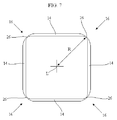
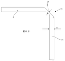
- thin wall portions 26 form the interconnections 16 between wall portions 14.
- the thin wall portions 26 are configured to decrease bending moment at the interconnection 16 so that it is substantially less than the bending moment at the wall portions.
- the bending moment at the interconnections is not zero because the thin wall portion has some stiffness.
- the thickness of the thin wall portions is selected so that relatively little radial, or lateral, compressive force is generated in the thin wall portion which would otherwise resist relative movement between adjacent wall portions 14.
- the ratio of the thickness t of the thin wall portion to the radial or lateral distance R between the longitudinal axis and the corner is preferably equal to or less than 1:10 and more preferably less than 1:20.
- corner thickness 't' and wall thickness 'T' depend on the specific size and demands imposed by the system requirements, i.e. available space & missile calibre.
- An exemplary aspect ratio of t:T is 5/18 (i.e. 0.28) but this could vary according to the working pressure for example between 0.28 +/- 0.5.
- the bending moment diagram for a wall portion 14 of the missile canister shown in Figures 7 and 8 is as shown in Figure 6C .
- the bending moment -B16 at the interconnections 16 is substantially less than the bending moment B14 at the centre of the wall portions 14.
- an inflection occurs at B0 where the bending moment in the wall portion is zero.
- the inflection points occur relatively close to the corner, and the bending moment B16 is substantially less than the bending moment B14.
- the wall portions are configured to resist compressive and tensile loads and shear stresses through the wall.
- the vessel is constructed from a composite material which behaves similarly to an I-beam.
- the wall portions 14 comprise a skin 28 covering a core 30.
- the tensile and compressive loads are carried by the skin, similarly the flange of an I-beam, whilst shear stresses are carried by the core, like the web of an I-beam.
- the skin may be formed from carbon fibre reinforced plastics whilst the core may comprise a tessellated configuration, such as a honeycomb, which has high compressive strength.
- the interconnecting portions 16 may comprise a high tensile skin 28 covering a low compression flexible core 32, which may be a low density foam material.
- the skin 28 may extend around the entire periphery of the wall portions 14 and interconnecting portions 16 of the canister. Additional reinforcing elements or inserts may be provided for attaching items such as a breech, arrestors, or missile connections. The reinforcing elements provide additional strength by spreading the applied load over the composite material.
- the materials of the wall portions may not be homogenous throughout the longitudinal extent of the canister.
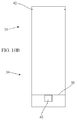
- the breech end portion 34 may be formed from different materials having different properties than the materials forming the muzzle end portion 36.
- the breech end portion 34 accommodates the means for propelling a missile from the canister whereas the muzzle end portion 36 accommodates the forward part of the missile.
- the breech end portion 34 accommodates a rocket motor which is ignited to eject a missile from the canister.
- the breech end portion 34 in a cold launch system, the breech end portion 34 accommodates a piston 38 and an energetic material 40 which is ignited to propel the piston along the tube. This movement of the piston ejects a missile from the canister.
- Piston arresters 42 are provided for retaining the piston in the canister after launch.
- the material properties of the breech end portion 34 are designed to withstand greater stresses that those of the muzzle end portion.
- the core of the breech end portion has greater compressive strength than that of the core of the muzzle end portion.
- the core of the breech end portion may be formed of a high density foam, whereas the core of the muzzle end portion may be formed of a low density foam.
Landscapes
- Engineering & Computer Science (AREA)
- General Engineering & Computer Science (AREA)
- Filling Or Discharging Of Gas Storage Vessels (AREA)
- Aiming, Guidance, Guns With A Light Source, Armor, Camouflage, And Targets (AREA)
Description
- This invention relates to a missile canister.
- Missile canisters are used to accommodate missiles during transit to provide protection. Missiles can also be deployed in missile canisters ready for launch and may be stacked together in a multi-canister missile system.
- The current state of the art for launching missiles is generally divided into two categories, namely hard launch and cold launch.
- In a hard launch system, the missile motor is ignited while the missile is in a missile launch canister. This approach requires significant efflux management due to the forces and debris produced as a consequence of allowing the primary missile launch motor to be ignited within the launch tube. In such a launch system the missile accelerates rapidly and conducts turnover with a high vertical velocity component.
- In a cold launch system, the missile rocket motor is ignited only after it has been "pushed" out of its canister and in some instances orientated towards its intended flight path. Cold launch systems include apparatus in the launch tube to eject a missile from the tube.
- Hard and cold launch systems require missile canisters for accommodating missiles during transit and prior to launch. In multi-canister systems, a plurality of canisters are stacked together one adjacent to another. Such multi-canister systems can be employed to launch multiple missiles in a relatively short period.
- Typically, a
missile canister 100 is formed of acylindrical vessel 102 having a circular cross-section which accommodates amissile 104 along its longitudinal axis, as shown inFigure 11 . A circular cross-section is well suited for withstanding the forces caused by the high gas pressures generated during launch of a missile. In this regard, the high pressure generally gives rise to hoop stress in the circular vessel and the load is generally distributed evenly about the circumference without causing significant stress points. Missile canisters can therefore be fabricated from metallic material which are relatively easy to manufacture and have a high tensile strength to resist the circumferential stress field. - However, since a missile canister must accommodate not only the body of a missile but also the wings or
fins 106 of the missile, a circular canister must have a radius which is sufficiently large to accommodate the most radially outward portion of the missile, which typically means the wings or fins. Consequently, there is a relatively large internal volume V1 which is unoccupied when a missile is accommodated within the canister causing inefficient use of space. - Further, as shown in
Figure 12 , circular missile canisters are inherently unsuited for stacking for transport and deployment, and are relatively unstable. When stacked together, there is a relatively large volume V2 left unused between the canisters meaning that the stacked canisters have an unnecessarily high foot-print. It will also be appreciated thattransport containers 108 are typically rectilinear and therefore the volume V3 may also cause inefficient use of space. - Swiss patent number
411626 -
US patent number 5,833,782 assigned to the United States of America as represented by the Secretary of the Navy discloses a blast container having a box-like structure. - The present invention provides an improved missile canister.
- Therefore, the present invention provides a missile canister for accommodating a missile along a longitudinal axis of the canister, the canister comprising a plurality of generally planar longitudinal wall portions connected together to form a tubular vessel having a polygonal cross-section, the interconnecting portions between wall sections being generally flexible so that when a missile is launched the bending moment at the interconnecting portions generated by the increase of pressure in the vessel is substantially less
than the bending moment generated at the wall portions, the interconnecting portions comprising a thin wall section relative to the thickness of the wall portions. - In this way, the corners behave similarly to a pivot point about which bending moment is reduced so that stress on the canister is resisted by walls rather than the corners.
- In order that the present invention may be well understood, embodiments thereof, which are given by way of example only, will now be described with reference to the accompanying drawings, in which:
-
Figure 1 shows a rectangular missile canister; -
Figure 2 shows a cross-section of the missile canister accommodating a missile; -
Figure 3 shows a plurality of such missile canisters stacked together; -
Figure 4 shows a typical loading distribution along one wall of a square missile canister; -
Figure 5 shows a simplified bending moment diagram for one canister wall shown inFigure 4 ; -
Figures 6A shows a typical loading distribution for a canister wall embodying the invention; -
Figures 6B and 6C show bending moment diagrams for a canister wall embodying the invention; -
Figure 7 shows a cross-section through the canister; -
Figure 8 shows part of the canister in more detail; -
Figure 9 shows a material construction of the canister; -
Figure 10A and10B show a further missile canister; -
Figure 11 shows a missile accommodated in a circular missile canister; and -
Figure 12 shows a plurality of circular missile canisters stacked together. - Referring to
Figure 1 , amissile canister 10 is shown for accommodating a missile along a longitudinal axis of the canister. The canister comprises a plurality of generally planar rectilinearlongitudinal wall portions 14 connected together to form atubular vessel 12 having a polygonal cross-section. As shown in this example a generally square cross-section is formed although depending on the configuration of the missile, other cross-sectional shapes may be preferred, such as triangular, rectangular or pentagonal.Interconnections 16 are provided between wall sections. As described in greater detail below theinterconnections 16 are generally flexible so that when a missile is launched the bending moment at the interconnections generated by the increase of pressure in the vessel is substantially less than the bending moment generated at thewall portions 14. -
Figure 2 shows amissile 20 accommodated in themissile canister 10. As the canister has a square cross-section, the fourfins 22 of the missile are received in the corners formed by theinterconnections 16 between thewall portions 14. In this regard, the lateral distance of the vessel from the central longitudinal axis L of the canister is greatest at the corner which is coincident with the most radially outermost portions of the missile. Thewall portions 14 of the vessel are closer to the axis L and therefore the unoccupied or void volume V4 of the canister is less than the void V1 shown inFigure 11 . Accordingly, the canister utilises space more efficiently. Other missile configurations, for example, with say three or five fins, would require a canister having a triangular or pentagonal cross-section. - Additionally, as shown in
Figure 3 , thecanisters 10 can be more efficiently stacked together for transport and deployment thereby efficiently utilising space inside atransport container 24 or when deployed on for example a vehicle or ship. In this regard, the volume V5 between the canisters is close to zero and the volume V6 between the stack and a container may also be relatively small. - A cross-sectional view of part of a typical square canister is shown in
Figure 4 . A corner C is shown interconnecting two adjacent wall portions W. During use of a missile accommodated in the canister, high gas pressures are generated within the canister which cause significant deflection of the wall portions in a outward direction D. The corners C are stiff and therefore the deflections cause a high bending moment and consequent stress at the corners. The highest bending stresses are generated in regions R in the interconnecting portions proximate the corners. -
Figure 5 approximates the bending moments in a canister wall portion W extending between two stiff corners C. The force applied by the gas pressure is shown by a uniformly distributed load L. It will be appreciated that the exact loading on the canister is somewhat more complicated than represented inFigure 5 but the Figure is sufficient for explaining the behaviour of the canister in use. - The bending moment Bw at the centre of the wall portion W is less than the bending moment -Be at the corners. The bending moment at the centre of the wall portion is positive whereas the bending moment at the corners is negative, the inflection occurring where bending moment is zero at B0. This bending moment distribution is caused because the corners are stiff and resist relative angular movement of the adjacent wall portions at the corners. The high bending stress at the corners of the canister can be resisted by strengthening the corners, either by increasing the thickness of the canister or by providing reinforcing struts extending between adjacent wall portions at the corner. Both these solutions complicate the construction of the canister and increase cost. Further, reinforcing struts occupy space which could otherwise be occupied by the fins of missile and therefore require an increase in the size of the canister.
- Embodiments of the present invention overcome the significant stresses which occur at the corners of the missile canister not by increasing the strength of the corners portions, but rather the interconnections between the wall portions are weakened. The weakened corners are flexible and allow movement between adjacent wall portions at the corner. Therefore, the bending moment at the corners is reduced such that it is substantially less than the bending moment in the wall portion.
- An approximation of the bending moments generated in embodiments of the invention is shown in
Figure 6. Figure 6A is awall portion 14 extending betweeninterconnections 16. The forces provided by the high gas pressure generated in use of the canister are shown by uniformly distributed load L. Theinterconnections 16 are represented by simple supports which by definition are perfect pivot points about which bending moment is zero. In this configuration, the distribution of bending moments is shown inFigure 6B , in which bending moment B16 at the interconnections is zero and the bending moment B14 at the centre of the wall portion 15 is relatively large. Therefore bending stress at the corners is significantly reduced compared to a typical square canister. - The theoretical bending moment diagram shown in
Figure 6B may not be achievable in practice because of the additional requirements of a missile canister. For example, aninterconnection 16 may be formed by a hinge functioning as a simple support. However, there is also a requirement that the canister contains high pressure gas without allowing gas to escape. The configuration of a hinge may not be suited therefore for use in a missile canister. - In one preferred embodiment of the present invention as shown in
Figure 7 and8 ,thin wall portions 26 form theinterconnections 16 betweenwall portions 14. Thethin wall portions 26 are configured to decrease bending moment at theinterconnection 16 so that it is substantially less than the bending moment at the wall portions. The bending moment at the interconnections is not zero because the thin wall portion has some stiffness. However, the thickness of the thin wall portions is selected so that relatively little radial, or lateral, compressive force is generated in the thin wall portion which would otherwise resist relative movement betweenadjacent wall portions 14. In this regard, the ratio of the thickness t of the thin wall portion to the radial or lateral distance R between the longitudinal axis and the corner is preferably equal to or less than 1:10 and more preferably less than 1:20. - The corner thickness 't' and wall thickness 'T' depend on the specific size and demands imposed by the system requirements, i.e. available space & missile calibre. An exemplary aspect ratio of t:T is 5/18 (i.e. 0.28) but this could vary according to the working pressure for example between 0.28 +/- 0.5.
- In this way, the bending moment diagram for a
wall portion 14 of the missile canister shown inFigures 7 and8 is as shown inFigure 6C . In this latter Figure, the bending moment -B16 at theinterconnections 16 is substantially less than the bending moment B14 at the centre of thewall portions 14. However, as thethin wall portions 26 have some internal stiffness, an inflection occurs at B0 where the bending moment in the wall portion is zero. However, compared toFigure 5 , the inflection points occur relatively close to the corner, and the bending moment B16 is substantially less than the bending moment B14. - The wall portions are configured to resist compressive and tensile loads and shear stresses through the wall. In one arrangement shown in
Figure 9 , the vessel is constructed from a composite material which behaves similarly to an I-beam. Thewall portions 14 comprise askin 28 covering acore 30. The tensile and compressive loads are carried by the skin, similarly the flange of an I-beam, whilst shear stresses are carried by the core, like the web of an I-beam. The skin may be formed from carbon fibre reinforced plastics whilst the core may comprise a tessellated configuration, such as a honeycomb, which has high compressive strength. The interconnectingportions 16 may comprise a hightensile skin 28 covering a low compressionflexible core 32, which may be a low density foam material. Theskin 28 may extend around the entire periphery of thewall portions 14 and interconnectingportions 16 of the canister. Additional reinforcing elements or inserts may be provided for attaching items such as a breech, arrestors, or missile connections. The reinforcing elements provide additional strength by spreading the applied load over the composite material. - The materials of the wall portions may not be homogenous throughout the longitudinal extent of the canister. As shown in
Figure 10A , thebreech end portion 34 may be formed from different materials having different properties than the materials forming themuzzle end portion 36. In use, thebreech end portion 34 accommodates the means for propelling a missile from the canister whereas themuzzle end portion 36 accommodates the forward part of the missile. In a hard launch system, thebreech end portion 34 accommodates a rocket motor which is ignited to eject a missile from the canister. As shown inFigure 10B , in a cold launch system, thebreech end portion 34 accommodates apiston 38 and anenergetic material 40 which is ignited to propel the piston along the tube. This movement of the piston ejects a missile from the canister.Piston arresters 42 are provided for retaining the piston in the canister after launch. - It will be appreciated that in either hard or cold systems, on launch greater gas pressure is generated in the
breech end portion 34 of the canister than themuzzle end portion 36. Accordingly, the material properties of thebreech end portion 34 are designed to withstand greater stresses that those of the muzzle end portion. If the canister is made from a composite material, the core of the breech end portion has greater compressive strength than that of the core of the muzzle end portion. For example the core of the breech end portion may be formed of a high density foam, whereas the core of the muzzle end portion may be formed of a low density foam.
Claims (8)
- A missile canister (10) for accommodating a missile (20) along a longitudinal axis of the canister, the canister comprising a plurality of generally planar longitudinal wall portions (14) connected together to form a tubular vessel having a polygonal cross-section,
characterised in that the interconnecting portions (16) between wall sections are generally flexible so that when a missile (20) is launched the bending moment at the interconnecting portions (16) generated by the increase of pressure in the vessel is substantially less than the bending moment generated at the wall portions (14), the interconnecting portions (16) comprising a thin wall section relative to the thickness of the wall portions (14). - A missile canister (10) as claimed in claim 1, wherein the interconnecting portions (16) allow relative angular deflection between adjacent wall portions (14) at respective interconnecting portions when a missile (20) is launched.
- A missile canister (10) as claimed in claims 1 or 2, wherein the interconnecting portions (16) generally simply support the wall portions (14) therebetween.
- A missile canister as claimed in any of the preceding claims, wherein the thickness 'T'" of the thin wall sections of the interconnecting portions (16) relative to the thickness 'T' of the wall
portions (14) is 0.28 +/- 0.5. - A missile canister (10) as claimed in any of the preceding claims, wherein the interconnecting portions (16) have relatively high tensile strength in a hoop direction and relatively low compressive strength in a radial direction.
- A missile canister (10) as claimed in any of the preceding claims, wherein the wall portions (14) have relatively high tensile strength in a hoop direction and relatively high compressive strength in a radial direction.
- A missile canister (10) as claimed in any of the preceding claims, wherein the missile canister (10) is made from a composite material having a skin (28) which has a high tensile strength in the hoop direction and a core (30, 32) which in the wall portions (14) has a high compressive strength in a radial direction and which in the interconnecting portions (16) has a low compressive strength in a radial direction.
- A missile canister (10) as claimed in any of the preceding claims, wherein the canister (10) comprises a breech end portion (34) and a muzzle end portion (36), and the wall portions (14) are configured to have greater strength in the breech end portion (34) than in the muzzle end portion (36).
Priority Applications (1)
| Application Number | Priority Date | Filing Date | Title |
|---|---|---|---|
| EP11745574.1A EP2606307B1 (en) | 2010-08-17 | 2011-08-15 | Missile canister |
Applications Claiming Priority (4)
| Application Number | Priority Date | Filing Date | Title |
|---|---|---|---|
| GBGB1013740.4A GB201013740D0 (en) | 2010-08-17 | 2010-08-17 | Missile canister |
| EP10251453A EP2420792A1 (en) | 2010-08-17 | 2010-08-17 | Missile canister |
| PCT/GB2011/051536 WO2012022964A1 (en) | 2010-08-17 | 2011-08-15 | Missile canister |
| EP11745574.1A EP2606307B1 (en) | 2010-08-17 | 2011-08-15 | Missile canister |
Publications (2)
| Publication Number | Publication Date |
|---|---|
| EP2606307A1 EP2606307A1 (en) | 2013-06-26 |
| EP2606307B1 true EP2606307B1 (en) | 2016-11-23 |
Family
ID=45604810
Family Applications (1)
| Application Number | Title | Priority Date | Filing Date |
|---|---|---|---|
| EP11745574.1A Active EP2606307B1 (en) | 2010-08-17 | 2011-08-15 | Missile canister |
Country Status (6)
| Country | Link |
|---|---|
| US (1) | US8973480B2 (en) |
| EP (1) | EP2606307B1 (en) |
| AU (1) | AU2011290563B2 (en) |
| CA (1) | CA2808009C (en) |
| ES (1) | ES2616262T3 (en) |
| WO (1) | WO2012022964A1 (en) |
Families Citing this family (1)
| Publication number | Priority date | Publication date | Assignee | Title |
|---|---|---|---|---|
| US20260084814A1 (en) * | 2024-09-20 | 2026-03-26 | Bae Systems Information And Electronic Systems Integration Inc. | Countermeasure dispenser system |
Family Cites Families (6)
| Publication number | Priority date | Publication date | Assignee | Title |
|---|---|---|---|---|
| CH411626A (en) | 1964-05-08 | 1966-04-15 | Contraves Ag | Small missile with four stabilizing wings |
| US5115711A (en) * | 1991-03-25 | 1992-05-26 | Fmc Corporation | Missile canister and method of fabrication |
| US5654053A (en) * | 1995-06-15 | 1997-08-05 | The United States Of America As Represented By The Secretary Of The Navy | High-energy-absorbing enclosure for internal explosion containment |
| US6584882B2 (en) * | 2001-01-22 | 2003-07-01 | Lockheed Martin Corporation | Self-contained canister missile launcher with tubular exhaust uptake ducts |
| US7165484B2 (en) * | 2002-09-05 | 2007-01-23 | Industrial Technology Research Institute | Blast-resistant cargo container |
| TWI264341B (en) * | 2005-09-13 | 2006-10-21 | Chenfeng Machinery & Entpr Co | Method of fabricating aluminum alloy launcher tube and the equipment used thereby |
-
2011
- 2011-08-15 AU AU2011290563A patent/AU2011290563B2/en active Active
- 2011-08-15 EP EP11745574.1A patent/EP2606307B1/en active Active
- 2011-08-15 US US13/816,850 patent/US8973480B2/en active Active
- 2011-08-15 WO PCT/GB2011/051536 patent/WO2012022964A1/en not_active Ceased
- 2011-08-15 ES ES11745574.1T patent/ES2616262T3/en active Active
- 2011-08-15 CA CA2808009A patent/CA2808009C/en active Active
Non-Patent Citations (1)
| Title |
|---|
| None * |
Also Published As
| Publication number | Publication date |
|---|---|
| US8973480B2 (en) | 2015-03-10 |
| CA2808009A1 (en) | 2012-02-23 |
| WO2012022964A1 (en) | 2012-02-23 |
| CA2808009C (en) | 2017-12-12 |
| AU2011290563A1 (en) | 2013-03-14 |
| US20130139676A1 (en) | 2013-06-06 |
| ES2616262T3 (en) | 2017-06-12 |
| AU2011290563B2 (en) | 2015-02-12 |
| EP2606307A1 (en) | 2013-06-26 |
Similar Documents
| Publication | Publication Date | Title |
|---|---|---|
| US6584882B2 (en) | Self-contained canister missile launcher with tubular exhaust uptake ducts | |
| US20150159587A1 (en) | Cluster rocket motor boosters | |
| US20120135180A1 (en) | Structural component and method for producing a structural component | |
| KR20200086740A (en) | Flexible satellite for deployment from attached hub | |
| EP2420792A1 (en) | Missile canister | |
| GB2555657A (en) | Deployable mast structure | |
| US5642867A (en) | Aerodynamic lifting and control surface and control system using same | |
| US8474760B2 (en) | Polygonal support structure | |
| US20190118926A1 (en) | Fuselage structure for an aircraft, and aircraft | |
| US12481287B2 (en) | Monolithic attitude control motor frame and system | |
| CA2808009C (en) | Missile canister | |
| US8002219B2 (en) | Multi-functional annular fairing for coupling launch abort motor to space vehicle | |
| US9151579B2 (en) | Non-circular cross-section missile components, missiles incorporating same, and methods of operation | |
| EP2335006B1 (en) | Projectile having fins with spiracles | |
| JP5566643B2 (en) | A bundle containing two pairs of tanks and an air launch launcher containing such a bundle | |
| US5467889A (en) | Nestable elastic fuel tank and method for making same | |
| Tam et al. | Conceptual design of space efficient tanks | |
| EP2335007B1 (en) | Projectile with filler material between fins and fuselage | |
| US12391408B2 (en) | Manned space station with solid structure | |
| RU2327050C2 (en) | Solid-propellant rocket enfine case from "cocoon'-type composite materials | |
| RU2749468C1 (en) | Adapter for several payloads in the form of a shell made of polymer composite materials | |
| US20050284085A1 (en) | Multi-purpose laminate beam | |
| Esslinger et al. | Design of high performance missile structures utilizing advanced composite material technologies |
Legal Events
| Date | Code | Title | Description |
|---|---|---|---|
| PUAI | Public reference made under article 153(3) epc to a published international application that has entered the european phase |
Free format text: ORIGINAL CODE: 0009012 |
|
| 17P | Request for examination filed |
Effective date: 20130218 |
|
| AK | Designated contracting states |
Kind code of ref document: A1 Designated state(s): AL AT BE BG CH CY CZ DE DK EE ES FI FR GB GR HR HU IE IS IT LI LT LU LV MC MK MT NL NO PL PT RO RS SE SI SK SM TR |
|
| DAX | Request for extension of the european patent (deleted) | ||
| GRAP | Despatch of communication of intention to grant a patent |
Free format text: ORIGINAL CODE: EPIDOSNIGR1 |
|
| INTG | Intention to grant announced |
Effective date: 20160726 |
|
| GRAS | Grant fee paid |
Free format text: ORIGINAL CODE: EPIDOSNIGR3 |
|
| GRAA | (expected) grant |
Free format text: ORIGINAL CODE: 0009210 |
|
| AK | Designated contracting states |
Kind code of ref document: B1 Designated state(s): AL AT BE BG CH CY CZ DE DK EE ES FI FR GB GR HR HU IE IS IT LI LT LU LV MC MK MT NL NO PL PT RO RS SE SI SK SM TR |
|
| REG | Reference to a national code |
Ref country code: GB Ref legal event code: FG4D |
|
| REG | Reference to a national code |
Ref country code: CH Ref legal event code: EP |
|
| REG | Reference to a national code |
Ref country code: IE Ref legal event code: FG4D |
|
| REG | Reference to a national code |
Ref country code: AT Ref legal event code: REF Ref document number: 848312 Country of ref document: AT Kind code of ref document: T Effective date: 20161215 |
|
| REG | Reference to a national code |
Ref country code: DE Ref legal event code: R096 Ref document number: 602011032704 Country of ref document: DE |
|
| REG | Reference to a national code |
Ref country code: SE Ref legal event code: TRGR |
|
| PG25 | Lapsed in a contracting state [announced via postgrant information from national office to epo] |
Ref country code: LV Free format text: LAPSE BECAUSE OF FAILURE TO SUBMIT A TRANSLATION OF THE DESCRIPTION OR TO PAY THE FEE WITHIN THE PRESCRIBED TIME-LIMIT Effective date: 20161123 |
|
| REG | Reference to a national code |
Ref country code: LT Ref legal event code: MG4D |
|
| REG | Reference to a national code |
Ref country code: NL Ref legal event code: MP Effective date: 20161123 |
|
| REG | Reference to a national code |
Ref country code: AT Ref legal event code: MK05 Ref document number: 848312 Country of ref document: AT Kind code of ref document: T Effective date: 20161123 |
|
| PG25 | Lapsed in a contracting state [announced via postgrant information from national office to epo] |
Ref country code: NL Free format text: LAPSE BECAUSE OF FAILURE TO SUBMIT A TRANSLATION OF THE DESCRIPTION OR TO PAY THE FEE WITHIN THE PRESCRIBED TIME-LIMIT Effective date: 20161123 Ref country code: GR Free format text: LAPSE BECAUSE OF FAILURE TO SUBMIT A TRANSLATION OF THE DESCRIPTION OR TO PAY THE FEE WITHIN THE PRESCRIBED TIME-LIMIT Effective date: 20170224 Ref country code: LT Free format text: LAPSE BECAUSE OF FAILURE TO SUBMIT A TRANSLATION OF THE DESCRIPTION OR TO PAY THE FEE WITHIN THE PRESCRIBED TIME-LIMIT Effective date: 20161123 Ref country code: NO Free format text: LAPSE BECAUSE OF FAILURE TO SUBMIT A TRANSLATION OF THE DESCRIPTION OR TO PAY THE FEE WITHIN THE PRESCRIBED TIME-LIMIT Effective date: 20170223 |
|
| PG25 | Lapsed in a contracting state [announced via postgrant information from national office to epo] |
Ref country code: HR Free format text: LAPSE BECAUSE OF FAILURE TO SUBMIT A TRANSLATION OF THE DESCRIPTION OR TO PAY THE FEE WITHIN THE PRESCRIBED TIME-LIMIT Effective date: 20161123 Ref country code: PL Free format text: LAPSE BECAUSE OF FAILURE TO SUBMIT A TRANSLATION OF THE DESCRIPTION OR TO PAY THE FEE WITHIN THE PRESCRIBED TIME-LIMIT Effective date: 20161123 Ref country code: RS Free format text: LAPSE BECAUSE OF FAILURE TO SUBMIT A TRANSLATION OF THE DESCRIPTION OR TO PAY THE FEE WITHIN THE PRESCRIBED TIME-LIMIT Effective date: 20161123 Ref country code: FI Free format text: LAPSE BECAUSE OF FAILURE TO SUBMIT A TRANSLATION OF THE DESCRIPTION OR TO PAY THE FEE WITHIN THE PRESCRIBED TIME-LIMIT Effective date: 20161123 Ref country code: AT Free format text: LAPSE BECAUSE OF FAILURE TO SUBMIT A TRANSLATION OF THE DESCRIPTION OR TO PAY THE FEE WITHIN THE PRESCRIBED TIME-LIMIT Effective date: 20161123 Ref country code: PT Free format text: LAPSE BECAUSE OF FAILURE TO SUBMIT A TRANSLATION OF THE DESCRIPTION OR TO PAY THE FEE WITHIN THE PRESCRIBED TIME-LIMIT Effective date: 20170323 |
|
| REG | Reference to a national code |
Ref country code: ES Ref legal event code: FG2A Ref document number: 2616262 Country of ref document: ES Kind code of ref document: T3 Effective date: 20170612 |
|
| PG25 | Lapsed in a contracting state [announced via postgrant information from national office to epo] |
Ref country code: CZ Free format text: LAPSE BECAUSE OF FAILURE TO SUBMIT A TRANSLATION OF THE DESCRIPTION OR TO PAY THE FEE WITHIN THE PRESCRIBED TIME-LIMIT Effective date: 20161123 Ref country code: EE Free format text: LAPSE BECAUSE OF FAILURE TO SUBMIT A TRANSLATION OF THE DESCRIPTION OR TO PAY THE FEE WITHIN THE PRESCRIBED TIME-LIMIT Effective date: 20161123 Ref country code: DK Free format text: LAPSE BECAUSE OF FAILURE TO SUBMIT A TRANSLATION OF THE DESCRIPTION OR TO PAY THE FEE WITHIN THE PRESCRIBED TIME-LIMIT Effective date: 20161123 Ref country code: SK Free format text: LAPSE BECAUSE OF FAILURE TO SUBMIT A TRANSLATION OF THE DESCRIPTION OR TO PAY THE FEE WITHIN THE PRESCRIBED TIME-LIMIT Effective date: 20161123 Ref country code: RO Free format text: LAPSE BECAUSE OF FAILURE TO SUBMIT A TRANSLATION OF THE DESCRIPTION OR TO PAY THE FEE WITHIN THE PRESCRIBED TIME-LIMIT Effective date: 20161123 |
|
| REG | Reference to a national code |
Ref country code: FR Ref legal event code: PLFP Year of fee payment: 7 |
|
| REG | Reference to a national code |
Ref country code: DE Ref legal event code: R097 Ref document number: 602011032704 Country of ref document: DE |
|
| PG25 | Lapsed in a contracting state [announced via postgrant information from national office to epo] |
Ref country code: BE Free format text: LAPSE BECAUSE OF FAILURE TO SUBMIT A TRANSLATION OF THE DESCRIPTION OR TO PAY THE FEE WITHIN THE PRESCRIBED TIME-LIMIT Effective date: 20161123 Ref country code: SM Free format text: LAPSE BECAUSE OF FAILURE TO SUBMIT A TRANSLATION OF THE DESCRIPTION OR TO PAY THE FEE WITHIN THE PRESCRIBED TIME-LIMIT Effective date: 20161123 Ref country code: BG Free format text: LAPSE BECAUSE OF FAILURE TO SUBMIT A TRANSLATION OF THE DESCRIPTION OR TO PAY THE FEE WITHIN THE PRESCRIBED TIME-LIMIT Effective date: 20170223 |
|
| PLBE | No opposition filed within time limit |
Free format text: ORIGINAL CODE: 0009261 |
|
| STAA | Information on the status of an ep patent application or granted ep patent |
Free format text: STATUS: NO OPPOSITION FILED WITHIN TIME LIMIT |
|
| 26N | No opposition filed |
Effective date: 20170824 |
|
| PG25 | Lapsed in a contracting state [announced via postgrant information from national office to epo] |
Ref country code: SI Free format text: LAPSE BECAUSE OF FAILURE TO SUBMIT A TRANSLATION OF THE DESCRIPTION OR TO PAY THE FEE WITHIN THE PRESCRIBED TIME-LIMIT Effective date: 20161123 |
|
| REG | Reference to a national code |
Ref country code: CH Ref legal event code: PL |
|
| PG25 | Lapsed in a contracting state [announced via postgrant information from national office to epo] |
Ref country code: MC Free format text: LAPSE BECAUSE OF FAILURE TO SUBMIT A TRANSLATION OF THE DESCRIPTION OR TO PAY THE FEE WITHIN THE PRESCRIBED TIME-LIMIT Effective date: 20161123 |
|
| PG25 | Lapsed in a contracting state [announced via postgrant information from national office to epo] |
Ref country code: LI Free format text: LAPSE BECAUSE OF NON-PAYMENT OF DUE FEES Effective date: 20170831 Ref country code: CH Free format text: LAPSE BECAUSE OF NON-PAYMENT OF DUE FEES Effective date: 20170831 |
|
| REG | Reference to a national code |
Ref country code: IE Ref legal event code: MM4A |
|
| PG25 | Lapsed in a contracting state [announced via postgrant information from national office to epo] |
Ref country code: LU Free format text: LAPSE BECAUSE OF NON-PAYMENT OF DUE FEES Effective date: 20170815 |
|
| PG25 | Lapsed in a contracting state [announced via postgrant information from national office to epo] |
Ref country code: IE Free format text: LAPSE BECAUSE OF NON-PAYMENT OF DUE FEES Effective date: 20170815 |
|
| REG | Reference to a national code |
Ref country code: FR Ref legal event code: PLFP Year of fee payment: 8 |
|
| PG25 | Lapsed in a contracting state [announced via postgrant information from national office to epo] |
Ref country code: MT Free format text: LAPSE BECAUSE OF NON-PAYMENT OF DUE FEES Effective date: 20170815 |
|
| PG25 | Lapsed in a contracting state [announced via postgrant information from national office to epo] |
Ref country code: HU Free format text: LAPSE BECAUSE OF FAILURE TO SUBMIT A TRANSLATION OF THE DESCRIPTION OR TO PAY THE FEE WITHIN THE PRESCRIBED TIME-LIMIT; INVALID AB INITIO Effective date: 20110815 |
|
| PG25 | Lapsed in a contracting state [announced via postgrant information from national office to epo] |
Ref country code: CY Free format text: LAPSE BECAUSE OF NON-PAYMENT OF DUE FEES Effective date: 20161123 |
|
| PG25 | Lapsed in a contracting state [announced via postgrant information from national office to epo] |
Ref country code: MK Free format text: LAPSE BECAUSE OF FAILURE TO SUBMIT A TRANSLATION OF THE DESCRIPTION OR TO PAY THE FEE WITHIN THE PRESCRIBED TIME-LIMIT Effective date: 20161123 |
|
| PG25 | Lapsed in a contracting state [announced via postgrant information from national office to epo] |
Ref country code: TR Free format text: LAPSE BECAUSE OF FAILURE TO SUBMIT A TRANSLATION OF THE DESCRIPTION OR TO PAY THE FEE WITHIN THE PRESCRIBED TIME-LIMIT Effective date: 20161123 |
|
| PG25 | Lapsed in a contracting state [announced via postgrant information from national office to epo] |
Ref country code: AL Free format text: LAPSE BECAUSE OF FAILURE TO SUBMIT A TRANSLATION OF THE DESCRIPTION OR TO PAY THE FEE WITHIN THE PRESCRIBED TIME-LIMIT Effective date: 20161123 Ref country code: IS Free format text: LAPSE BECAUSE OF FAILURE TO SUBMIT A TRANSLATION OF THE DESCRIPTION OR TO PAY THE FEE WITHIN THE PRESCRIBED TIME-LIMIT Effective date: 20170323 |
|
| PGFP | Annual fee paid to national office [announced via postgrant information from national office to epo] |
Ref country code: ES Payment date: 20250901 Year of fee payment: 15 |
|
| PGFP | Annual fee paid to national office [announced via postgrant information from national office to epo] |
Ref country code: DE Payment date: 20250724 Year of fee payment: 15 |
|
| PGFP | Annual fee paid to national office [announced via postgrant information from national office to epo] |
Ref country code: IT Payment date: 20250723 Year of fee payment: 15 |
|
| PGFP | Annual fee paid to national office [announced via postgrant information from national office to epo] |
Ref country code: GB Payment date: 20250725 Year of fee payment: 15 |
|
| PGFP | Annual fee paid to national office [announced via postgrant information from national office to epo] |
Ref country code: FR Payment date: 20250725 Year of fee payment: 15 |
|
| PGFP | Annual fee paid to national office [announced via postgrant information from national office to epo] |
Ref country code: SE Payment date: 20250723 Year of fee payment: 15 |