EP2605288A2 - Solar cell and solar cell module - Google Patents
Solar cell and solar cell module Download PDFInfo
- Publication number
- EP2605288A2 EP2605288A2 EP12192923.6A EP12192923A EP2605288A2 EP 2605288 A2 EP2605288 A2 EP 2605288A2 EP 12192923 A EP12192923 A EP 12192923A EP 2605288 A2 EP2605288 A2 EP 2605288A2
- Authority
- EP
- European Patent Office
- Prior art keywords
- solar cell
- substrate
- bridge
- contact electrode
- electrically connected
- Prior art date
- Legal status (The legal status is an assumption and is not a legal conclusion. Google has not performed a legal analysis and makes no representation as to the accuracy of the status listed.)
- Withdrawn
Links
- 239000000758 substrate Substances 0.000 claims abstract description 57
- 230000005540 biological transmission Effects 0.000 claims description 9
- 238000010586 diagram Methods 0.000 description 18
- XUIMIQQOPSSXEZ-UHFFFAOYSA-N Silicon Chemical compound [Si] XUIMIQQOPSSXEZ-UHFFFAOYSA-N 0.000 description 8
- 229910052710 silicon Inorganic materials 0.000 description 8
- 239000010703 silicon Substances 0.000 description 8
- 230000001419 dependent effect Effects 0.000 description 1
- 238000011161 development Methods 0.000 description 1
- 230000018109 developmental process Effects 0.000 description 1
- 230000005611 electricity Effects 0.000 description 1
- 238000009413 insulation Methods 0.000 description 1
- 239000000463 material Substances 0.000 description 1
Images



Classifications
-
- H—ELECTRICITY
- H10—SEMICONDUCTOR DEVICES; ELECTRIC SOLID-STATE DEVICES NOT OTHERWISE PROVIDED FOR
- H10F—INORGANIC SEMICONDUCTOR DEVICES SENSITIVE TO INFRARED RADIATION, LIGHT, ELECTROMAGNETIC RADIATION OF SHORTER WAVELENGTH OR CORPUSCULAR RADIATION
- H10F77/00—Constructional details of devices covered by this subclass
- H10F77/20—Electrodes
- H10F77/206—Electrodes for devices having potential barriers
- H10F77/211—Electrodes for devices having potential barriers for photovoltaic cells
-
- H—ELECTRICITY
- H10—SEMICONDUCTOR DEVICES; ELECTRIC SOLID-STATE DEVICES NOT OTHERWISE PROVIDED FOR
- H10F—INORGANIC SEMICONDUCTOR DEVICES SENSITIVE TO INFRARED RADIATION, LIGHT, ELECTROMAGNETIC RADIATION OF SHORTER WAVELENGTH OR CORPUSCULAR RADIATION
- H10F19/00—Integrated devices, or assemblies of multiple devices, comprising at least one photovoltaic cell covered by group H10F10/00, e.g. photovoltaic modules
- H10F19/90—Structures for connecting between photovoltaic cells, e.g. interconnections or insulating spacers
- H10F19/902—Structures for connecting between photovoltaic cells, e.g. interconnections or insulating spacers for series or parallel connection of photovoltaic cells
-
- H—ELECTRICITY
- H10—SEMICONDUCTOR DEVICES; ELECTRIC SOLID-STATE DEVICES NOT OTHERWISE PROVIDED FOR
- H10F—INORGANIC SEMICONDUCTOR DEVICES SENSITIVE TO INFRARED RADIATION, LIGHT, ELECTROMAGNETIC RADIATION OF SHORTER WAVELENGTH OR CORPUSCULAR RADIATION
- H10F77/00—Constructional details of devices covered by this subclass
- H10F77/93—Interconnections
- H10F77/933—Interconnections for devices having potential barriers
- H10F77/935—Interconnections for devices having potential barriers for photovoltaic devices or modules
- H10F77/937—Busbar structures for modules
-
- Y—GENERAL TAGGING OF NEW TECHNOLOGICAL DEVELOPMENTS; GENERAL TAGGING OF CROSS-SECTIONAL TECHNOLOGIES SPANNING OVER SEVERAL SECTIONS OF THE IPC; TECHNICAL SUBJECTS COVERED BY FORMER USPC CROSS-REFERENCE ART COLLECTIONS [XRACs] AND DIGESTS
- Y02—TECHNOLOGIES OR APPLICATIONS FOR MITIGATION OR ADAPTATION AGAINST CLIMATE CHANGE
- Y02E—REDUCTION OF GREENHOUSE GAS [GHG] EMISSIONS, RELATED TO ENERGY GENERATION, TRANSMISSION OR DISTRIBUTION
- Y02E10/00—Energy generation through renewable energy sources
- Y02E10/50—Photovoltaic [PV] energy
Definitions
- the present invention is related to a solar cell and a solar cell module capable of saving space and improving efficiency according to the pre-characterizing clauses of claims 1, 6 and 13.
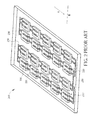
- FIG. 1 is a diagram showing a solar cell 100 of the prior art.
- FIG. 2 is a diagram showing a solar cell module 200 comprising the solar cells 100 of FIG. 1 .
- FIG. 3 is a diagram showing connections between the solar cells 100 of the solar cell module 200 of FIG. 2 .
- the solar cell 100 comprises a silicon substrate 110, a front bus 120, and a rear bus 130.
- the silicon substrate 110 has a front surface 112 and a rear surface 114.
- the silicon substrate 110 generates current when the front surface 112 receives light.
- the front bus 120 is located on the front surface 112 of the silicon substrate 110 along a first direction A for collecting current generated by the silicon substrate 110, and for providing a front contact electrode 122.
- the rear bus 130 is located on the rear surface 114 of the silicon substrate 110 along the first direction A for collecting current generated by the silicon substrate 110, and for providing a rear contact electrode 132.
- a polarity of the front contact electrode 122 is opposite to a polarity of the rear contact electrode 132.
- the solar cell module 200 comprises a plurality of solar cell strings 210. Each of the solar cell strings 210 comprises a plurality of solar cells 100 electrically connected to each other in series along the first direction A.
- the front contact electrode 122 of each solar cell 100 is electrically connected to the rear contact electrode 132 of adjacent solar cell 100 via a conducting strip 220.
- the solar cell module 200 further comprises conducting bars 230 arranged along a second direction B for electrically connecting the solar cell strings 210 in series.
- the conducting bars 230 are located around the solar cell strings 210 for being electrically connected with the conducting strips 220. According to the above arrangement, all the solar cell strings 210 are electrically connected in series for providing electricity.
- the conducting bars 230 are installed around the solar cell strings 210, the conducting bars 230 occupy part of space of the solar panel module 200, such that the solar panel module 200 of the prior art is not able to reduce size effectively.
- the present invention aims at providing a solar cell and a solar cell module capable of saving space and improving efficiency.
- the claimed solar cell comprised a substrate, a first front bus, and a first rear bus.
- the substrate has a front surface and a rear surface.
- the first front bus is located on the front surface of the substrate along a first direction for collecting current generated by the substrate, and for providing a first front contact electrode.
- the first rear bus is located on the rear surface of the substrate along a second direction different from the first direction for collecting current generated by the substrate, and for providing a first rear contact electrode.
- a first embodiment of the claimed solar cell module comprises a first solar cell string, a second solar cell string, and a first conducting strip.
- the first solar cell string comprises a plurality of first solar cells electrically connected to each other in series along a first direction, and the plurality of first solar cells comprises a first bridge solar cell.
- the second solar cell string comprises a plurality of second solar cells electrically connected to each other in series, and the plurality of second solar cells comprises a second bridge solar cell.
- the first conducting strip is for electrically connecting a surface of the first bridge solar cell to a surface of the second bridge solar cell along a second direction different from the first direction, wherein the plurality of second solar cells are electrically connected to each other in series along a third direction different from the second direction.
- a second embodiment of the claimed solar cell module comprises a first solar cell string, a second solar cell string, and a first conducting strip.
- the first solar cell string comprises a plurality of first solar cells electrically connected to each other in series along a first direction, and the plurality of first solar cells comprising a first bridge solar cell with a first lateral surface.
- the second solar cell string comprises a plurality of second solar cells electrically connected to each other in series along a second direction, and the plurality of second solar cells comprises a second bridge solar cell with a second lateral surface opposite to the first lateral surface, wherein a first space is formed between four edges of the first lateral surface and four edges of the second lateral surface.
- the first conducting strip is for electrically connecting the first bridge solar cell (to the second bridge solar cell, and the first conducting strip has a first contact part, a second contact part, and a transmission part, wherein the first contact part is electrically connected to the first bridge solar cell, the second contact part is electrically connected to the second bridge solar cell, and the transmission part connected between the first contact part and the second contact part is arranged inside the first space.
- the rear contact electrode and the front contact electrode of the solar cell of the present invention are arranged along different directions, such that the solar cell strings of the solar panel module of the present invention can be directly coupled to each other via the second conducting strip, the conducting bars installed around the solar cell strings are no longer necessary, so as to further reduce size of the solar panel module. Besides, the overall length of conducting wire of the solar panel module is reduced, such that the solar panel module of the present invention has better efficiency.
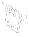
- FIG. 4 is a diagram showing a first embodiment of a solar cell of the present invention.
- the solar cell 400 of the present invention comprises a substrate 410, a front bus 420, and a rear bus 430.
- the substrate 410 can be made of silicon or any other photovoltaic material.
- the substrate 410 has a front surface 412 and a rear surface 414.
- the substrate 410 generates current when the front surface 412 receives light.
- the front bus 420 is located on the front surface 412 of the substrate 410 (in other words, the front bus 420 and the front surface 412 are at the same side of the solar cell 400)along a first direction A for collecting current generated by the substrate 410, and for providing a front contact electrode 422.
- the rear bus 430 is located on the rear surface 414 of the substrate 410 (in other words, the rear bus 430 and the rear surface 422 are at the same side of the solar cell 400) along a second direction B different from the first direction A (such as perpendicular to the first direction A) for collecting current generated by the substrate 410, and for providing a rear contact electrode 432.
- a polarity of the front contact electrode 422 is opposite to a polarity of the rear contact electrode 432.
- the solar cell 400 can further comprise a plurality of front finger buses 424 electrically connected to the front bus 420.
- the front finger buses 424 are extended from the front bus 420 for assisting the front bus 420 in collecting current.
- the contact electrode 422,432 provided by the front bus 420 and the rear bus 430 can be electrically connected to the front finger buses 424 via the conducting strips.
- FIG. 5 is a diagram showing an embodiment of a solar cell module of the present invention.
- FIG. 6 is a diagram showing connections between bridge solar cells of the solar cell module of FIG. 5 .
- the solar cell module 500 comprises a plurality of solar cell strings 510A, 510B, 510C, 510D.
- Each of the solar cell strings 510A, 510B, 510C, 510D comprises a plurality of solar cells 100 (as shown in FIG. 1 ) and at least one solar cell 400 (as shown in FIG. 1 ) electrically connected to each other in series along a first direction A.
- the front contact electrode 122 of each solar cell 100 is electrically connected to the rear contact electrode 132 of adjacent solar cell 100 via a first conducting strip 520.
- the solar cell module 500 further comprises second conducting strips 530 arranged along a second direction B for electrically connecting the solar cell strings 510 in series.
- the second conducting strips 530 are utilized for electrically connecting bridge solar cells 400A, 400B of the solar cell strings in series.
- Structure of the bridge solar cells 400A, 400B is the same as structure of the solar cell 400 (as shown in FIG. 4 ), the solar cell 700(as shown in FIG. 7 ), the solar cell 800(as shown in FIG. 8 ) or the solar cell 900(as shown in FIG. 9 ). As shown in FIG. 4 ), the solar cell 700(as shown in FIG. 7 ), the solar cell 800(as shown in FIG. 8 ) or the solar cell 900(as shown in FIG. 9 ). As shown in FIG. 4 ), the solar cell 700(as shown in FIG. 7 ), the solar
- the rear bus 430A of the bridge solar cell 400A of the solar cell string 510A is located on the rear surface of the substrate 410A along the second direction B
- the front bus 420B of the bridge solar cell 400B of the solar cell string 510B is located on the front surface of the substrate 410B along the second direction B, such that the second conducting strips 530 can be directly coupled to the bridge solar cell 400A of the solar cell strings 510A to the bridge solar cell 400B of the solar cell strings 510B in series along the second direction B.
- the front bus 420A of the bridge solar cell 400A can be perpendicular to the rear bus 430A
- the rear bus 430B of the bridge solar cell 400B can be perpendicular to the front bus 420B, such that the front bus 420A of the bridge solar cell 400A can be electrically connected with the other solar cell 100 of the solar cell string 510A along the first direction A, and the rear bus 430B of the bridge solar cell 400B can be electrically connected with the other solar cell 100 of the solar cell string 510B along the first direction A.
- the solar cells 100, 400 are generally located on an insulation back plate 540.
- the solar cell strings 510A, 510B, 510C, 510D may be arranged along different directions.
- the bridge solar cell 400A has a first lateral surface 440A
- bridge solar cell 400B has a second lateral surface 440B facing the first lateral surface 440A.
- a first space 550 is formed between four edges of the first lateral surface 440A and four edges of the second lateral surface 440B.
- the second conducting strip 530 can be divided into a first contact part 530_1, a second contact part 530_2, and a transmission part 530_3.
- the first contact part 530_1 is electrically connected to the rear bus 430A of the bridge solar cell 400A
- the second contact part 530_2 is electrically connected to the front bus 420B of the bridge solar cell 400B
- the transmission part 530_3 is connected between the first contact part 530_1 and the second contact part 530_2, wherein the transmission part 530_3 is arranged inside the first space.
- the solar cell module 500 of the present invention can save extra space around the solar cell strings 510A, 510B, 510C, 510D from installing the conducting bars to electrically connect the solar cell strings 510A, 510B, 510C, 510D in series. Therefore, the size of the solar cell module 500 can be further reduced.
- overall length of conducting wire of the solar cell module 500 of the present invention is shorter, such that the solar cell module 500 of the present invention has lower resistance, which reduces power consumption.
- FIG. 7 is a diagram showing a second embodiment of the solar cell of the present invention.
- the solar cell 700 comprises a first front bus 720, a second front bus 740, a first rear bus 730, and a second rear bus 750.
- the first front bus 720 is located on the front surface 712 of the substrate 710 along the first direction A.
- the second front bus 740 is located on the front surface 712 of the substrate 710 along the second direction B.
- the first rear bus 730 is located on the rear surface 714 of the substrate 710 along the second direction B.
- the second rear bus 750 is located on the rear surface 714 of the substrate 710 along the first direction A.
- the solar cell 700 can be utilized as one of the solar cells of the solar cell module 500 (as shown in Fig. 5 ).
- FIG. 8 is a diagram showing a third embodiment of the solar cell of the present invention.
- the rear contact electrode 832 of the solar cell 800 comprises a plurality of contact surfaces adjacent to each other.
- the rear contact electrode 832 of the solar cell 800 comprises a plurality of contact surfaces sequentially arranged along the second direction B.
- FIG. 9 is a diagram showing a fourth embodiment of the solar cell of the present invention.
- the rear contact electrode 932 of the solar cell 900 comprises two contact surfaces arranged at opposite edges of the rear surface of the substrate 910 respectively.
- the above solar cell 800, 900 can also be utilized as the bridge solar cell of the solar cell module 500 shown in FIG. 5 .
- the rear contact electrode it is not necessary for the rear contact electrode to be perpendicular to the front contact electrode in the present invention.
- the rear contact electrode can be arranged along any other direction different from the direction of the front contact electrode.
- the rear contact electrode and the front contact electrode of the solar cell of the embodiments of the present invention can be arranged along different directions, such that the solar cell strings of the solar cell module of the present invention can be directly coupled to each other via the second conducting strip, so as to further reduce the size of the solar cell module. Besides, the overall length of conducting wire of the solar cell module can be reduced, such that the solar cell module of the present invention is more efficient.
Landscapes
- Photovoltaic Devices (AREA)
- Life Sciences & Earth Sciences (AREA)
- Engineering & Computer Science (AREA)
- Sustainable Development (AREA)
- Sustainable Energy (AREA)
Abstract
Description
- The present invention is related to a solar cell and a solar cell module capable of saving space and improving efficiency according to the pre-characterizing clauses of claims 1, 6 and 13.
- Please refer to
FIG. 1 to FIG. 3 .FIG. 1 is a diagram showing asolar cell 100 of the prior art.FIG. 2 is a diagram showing asolar cell module 200 comprising thesolar cells 100 ofFIG. 1 .FIG. 3 is a diagram showing connections between thesolar cells 100 of thesolar cell module 200 ofFIG. 2 . Thesolar cell 100 comprises asilicon substrate 110, afront bus 120, and arear bus 130. Thesilicon substrate 110 has afront surface 112 and arear surface 114. Thesilicon substrate 110 generates current when thefront surface 112 receives light. Thefront bus 120 is located on thefront surface 112 of thesilicon substrate 110 along a first direction A for collecting current generated by thesilicon substrate 110, and for providing afront contact electrode 122. Therear bus 130 is located on therear surface 114 of thesilicon substrate 110 along the first direction A for collecting current generated by thesilicon substrate 110, and for providing arear contact electrode 132. A polarity of thefront contact electrode 122 is opposite to a polarity of therear contact electrode 132. Thesolar cell module 200 comprises a plurality ofsolar cell strings 210. Each of thesolar cell strings 210 comprises a plurality ofsolar cells 100 electrically connected to each other in series along the first direction A. Thefront contact electrode 122 of eachsolar cell 100 is electrically connected to therear contact electrode 132 of adjacentsolar cell 100 via a conductingstrip 220. Thesolar cell module 200 further comprises conductingbars 230 arranged along a second direction B for electrically connecting thesolar cell strings 210 in series. The conductingbars 230 are located around thesolar cell strings 210 for being electrically connected with the conductingstrips 220. According to the above arrangement, all thesolar cell strings 210 are electrically connected in series for providing electricity. - Because the conducting
bars 230 are installed around thesolar cell strings 210, the conductingbars 230 occupy part of space of thesolar panel module 200, such that thesolar panel module 200 of the prior art is not able to reduce size effectively. - This in mind, the present invention aims at providing a solar cell and a solar cell module capable of saving space and improving efficiency.
- This is achieved by a solar cell and a solar cell module according to the pre-characterizing clauses of claims 1, 6 and 13. The dependent claims pertain to corresponding further developments and improvements.
- As will be seen more clearly from the detailed description following below, the claimed solar cell comprised a substrate, a first front bus, and a first rear bus. The substrate has a front surface and a rear surface. The first front bus is located on the front surface of the substrate along a first direction for collecting current generated by the substrate, and for providing a first front contact electrode. The first rear bus is located on the rear surface of the substrate along a second direction different from the first direction for collecting current generated by the substrate, and for providing a first rear contact electrode.
- A first embodiment of the claimed solar cell module comprises a first solar cell string, a second solar cell string, and a first conducting strip. The first solar cell string comprises a plurality of first solar cells electrically connected to each other in series along a first direction, and the plurality of first solar cells comprises a first bridge solar cell. The second solar cell string comprises a plurality of second solar cells electrically connected to each other in series, and the plurality of second solar cells comprises a second bridge solar cell. The first conducting strip is for electrically connecting a surface of the first bridge solar cell to a surface of the second bridge solar cell along a second direction different from the first direction, wherein the plurality of second solar cells are electrically connected to each other in series along a third direction different from the second direction.
- A second embodiment of the claimed solar cell module comprises a first solar cell string, a second solar cell string, and a first conducting strip. The first solar cell string comprises a plurality of first solar cells electrically connected to each other in series along a first direction, and the plurality of first solar cells comprising a first bridge solar cell with a first lateral surface. The second solar cell string comprises a plurality of second solar cells electrically connected to each other in series along a second direction, and the plurality of second solar cells comprises a second bridge solar cell with a second lateral surface opposite to the first lateral surface, wherein a first space is formed between four edges of the first lateral surface and four edges of the second lateral surface. The first conducting strip is for electrically connecting the first bridge solar cell (to the second bridge solar cell, and the first conducting strip has a first contact part, a second contact part, and a transmission part, wherein the first contact part is electrically connected to the first bridge solar cell, the second contact part is electrically connected to the second bridge solar cell, and the transmission part connected between the first contact part and the second contact part is arranged inside the first space.
- The rear contact electrode and the front contact electrode of the solar cell of the present invention are arranged along different directions, such that the solar cell strings of the solar panel module of the present invention can be directly coupled to each other via the second conducting strip, the conducting bars installed around the solar cell strings are no longer necessary, so as to further reduce size of the solar panel module. Besides, the overall length of conducting wire of the solar panel module is reduced, such that the solar panel module of the present invention has better efficiency.
- In the following, the invention is further illustrated by way of example, taking reference to the accompanying drawings thereof:
-
FIG. 1 is a diagram showing a solar cell of the prior art, -
FIG. 2 is a diagram showing a solar cell module comprising the solar cells ofFIG. 1 , -
FIG. 3 is a diagram showing connections between the solar cells of the solar cell module ofFIG. 2 , -
FIG. 4 is a diagram showing a first embodiment of a solar cell of the present invention, -
FIG. 5 is a diagram showing an embodiment of a solar cell module of the present invention, -
FIG. 6 is a diagram showing connections between bridge solar cells of the solar cell module ofFIG. 5 , -
FIG. 7 is a diagram showing a second embodiment of the solar cell of the present invention, -
FIG. 8 is a diagram showing a third embodiment of the solar cell of the present invention, and -
FIG. 9 is a diagram showing a fourth embodiment of the solar cell of the present invention. - Please refer to
FIG. 4. FIG. 4 is a diagram showing a first embodiment of a solar cell of the present invention. Thesolar cell 400 of the present invention comprises asubstrate 410, afront bus 420, and arear bus 430. Thesubstrate 410 can be made of silicon or any other photovoltaic material. Thesubstrate 410 has afront surface 412 and arear surface 414. Thesubstrate 410 generates current when thefront surface 412 receives light. Thefront bus 420 is located on thefront surface 412 of the substrate 410 (in other words, thefront bus 420 and thefront surface 412 are at the same side of the solar cell 400)along a first direction A for collecting current generated by thesubstrate 410, and for providing afront contact electrode 422. Therear bus 430 is located on therear surface 414 of the substrate 410 (in other words, therear bus 430 and therear surface 422 are at the same side of the solar cell 400) along a second direction B different from the first direction A (such as perpendicular to the first direction A) for collecting current generated by thesubstrate 410, and for providing arear contact electrode 432. A polarity of thefront contact electrode 422 is opposite to a polarity of therear contact electrode 432. Thesolar cell 400 can further comprise a plurality offront finger buses 424 electrically connected to thefront bus 420. Thefront finger buses 424 are extended from thefront bus 420 for assisting thefront bus 420 in collecting current. The contact electrode 422,432 provided by thefront bus 420 and therear bus 430 can be electrically connected to thefront finger buses 424 via the conducting strips. - Please refer to
FIG. 5 andFIG. 6 .FIG. 5 is a diagram showing an embodiment of a solar cell module of the present invention.FIG. 6 is a diagram showing connections between bridge solar cells of the solar cell module ofFIG. 5 . Thesolar cell module 500 comprises a plurality of solar cell strings 510A, 510B, 510C, 510D. Each of the solar cell strings 510A, 510B, 510C, 510D comprises a plurality of solar cells 100 (as shown inFIG. 1 ) and at least one solar cell 400 (as shown inFIG. 1 ) electrically connected to each other in series along a first direction A. Thefront contact electrode 122 of eachsolar cell 100 is electrically connected to therear contact electrode 132 of adjacentsolar cell 100 via afirst conducting strip 520. Thesolar cell module 500 further comprises second conducting strips 530 arranged along a second direction B for electrically connecting the solar cell strings 510 in series. The second conducting strips 530 are utilized for electrically connecting bridgesolar cells solar cells FIG. 4 ), the solar cell 700(as shown inFIG. 7 ), the solar cell 800(as shown inFIG. 8 ) or the solar cell 900(as shown inFIG. 9 ). As shown inFIG. 6 , therear bus 430A of the bridgesolar cell 400A of thesolar cell string 510A is located on the rear surface of thesubstrate 410A along the second direction B, and thefront bus 420B of the bridgesolar cell 400B of thesolar cell string 510B is located on the front surface of thesubstrate 410B along the second direction B, such that the second conducting strips 530 can be directly coupled to the bridgesolar cell 400A of thesolar cell strings 510A to the bridgesolar cell 400B of the solar cell strings 510B in series along the second direction B. Moreover, the front bus 420A of the bridgesolar cell 400A can be perpendicular to therear bus 430A, and therear bus 430B of the bridgesolar cell 400B can be perpendicular to thefront bus 420B, such that the front bus 420A of the bridgesolar cell 400A can be electrically connected with the othersolar cell 100 of thesolar cell string 510A along the first direction A, and therear bus 430B of the bridgesolar cell 400B can be electrically connected with the othersolar cell 100 of thesolar cell string 510B along the first direction A. In addition, thesolar cells plate 540. The solar cell strings 510A, 510B, 510C, 510D may be arranged along different directions. - In other words, as shown in
FIG. 6 , the bridgesolar cell 400A has a firstlateral surface 440A, and bridgesolar cell 400B has a secondlateral surface 440B facing the firstlateral surface 440A. Afirst space 550 is formed between four edges of the firstlateral surface 440A and four edges of the secondlateral surface 440B. In addition, thesecond conducting strip 530 can be divided into a first contact part 530_1, a second contact part 530_2, and a transmission part 530_3. The first contact part 530_1 is electrically connected to therear bus 430A of the bridgesolar cell 400A, the second contact part 530_2 is electrically connected to thefront bus 420B of the bridgesolar cell 400B, and the transmission part 530_3 is connected between the first contact part 530_1 and the second contact part 530_2, wherein the transmission part 530_3 is arranged inside the first space. - According to the above arrangement, the
solar cell module 500 of the present invention can save extra space around the solar cell strings 510A, 510B, 510C, 510D from installing the conducting bars to electrically connect the solar cell strings 510A, 510B, 510C, 510D in series. Therefore, the size of thesolar cell module 500 can be further reduced. In addition, compared with the solar cell module of the prior art, overall length of conducting wire of thesolar cell module 500 of the present invention is shorter, such that thesolar cell module 500 of the present invention has lower resistance, which reduces power consumption. - Please refer to
FIG. 7. FIG. 7 is a diagram showing a second embodiment of the solar cell of the present invention. As shown inFIG. 7 , thesolar cell 700 comprises afirst front bus 720, asecond front bus 740, a firstrear bus 730, and a secondrear bus 750. Thefirst front bus 720 is located on thefront surface 712 of thesubstrate 710 along the first direction A. Thesecond front bus 740 is located on thefront surface 712 of thesubstrate 710 along the second direction B. The firstrear bus 730 is located on therear surface 714 of thesubstrate 710 along the second direction B. The secondrear bus 750 is located on therear surface 714 of thesubstrate 710 along the first direction A. Thus, thesolar cell 700 can be utilized as one of the solar cells of the solar cell module 500 (as shown inFig. 5 ). - Please refer to
FIG. 8. FIG. 8 is a diagram showing a third embodiment of the solar cell of the present invention. As shown inFIG. 8 , besides therear contact electrode 832 of thesolar cell 800 being perpendicular to thefront contact electrode 822, therear contact electrode 832 of thesolar cell 800 comprises a plurality of contact surfaces adjacent to each other. In other words, therear contact electrode 832 of thesolar cell 800 comprises a plurality of contact surfaces sequentially arranged along the second direction B. - Please refer to
FIG. 9. FIG. 9 is a diagram showing a fourth embodiment of the solar cell of the present invention. As shown inFIG. 9 , besides therear contact electrode 932 of thesolar cell 900 being perpendicular to thefront contact electrode 922, therear contact electrode 932 of thesolar cell 900 comprises two contact surfaces arranged at opposite edges of the rear surface of thesubstrate 910 respectively. - The above
solar cell solar cell module 500 shown inFIG. 5 . - In addition, it is not necessary for the rear contact electrode to be perpendicular to the front contact electrode in the present invention. The rear contact electrode can be arranged along any other direction different from the direction of the front contact electrode.
- The rear contact electrode and the front contact electrode of the solar cell of the embodiments of the present invention can be arranged along different directions, such that the solar cell strings of the solar cell module of the present invention can be directly coupled to each other via the second conducting strip, so as to further reduce the size of the solar cell module. Besides, the overall length of conducting wire of the solar cell module can be reduced, such that the solar cell module of the present invention is more efficient.
Claims (15)
- A solar cell (400, 700, 800, 900), comprising:a substrate (410, 710, 810, 910), having a front surface (412, 712) and a rear surface (414, 714);characterized by:a first front bus (420, 420A, 420B, 720), located on the front surface (412, 712) of the substrate (410, 710, 810, 910) along a first direction for collecting current generated by the substrate (410, 710, 810, 910), and for providing a first front contact electrode (422, 822, 922); anda first rear bus (430, 430A, 430B), located on the rear surface (414, 714) of the substrate (410, 710, 810, 910) along a second direction different from the first direction for collecting current generated by the substrate (410, 710, 810, 910), and for providing a first rear contact electrode (432, 832, 932).
- The solar cell of claim 1, further characterized by:a second front bus (740), located on the front surface (712) of the substrate (710) along the second direction for collecting current generated by the substrate (710), and for providing a second front contact electrode; anda second rear bus (750), located on the rear surface (714) of the substrate (710) along the first direction for collecting current generated by the substrate (710), and for providing a second rear contact electrode (132).
- The solar cell of claim 1, further characterized in that the first rear contact electrode (832, 932) comprises a plurality of electrodes sequentially arranged along the second direction.
- The solar cell of claim 1, further characterized in that the first rear contact electrode (832) comprises two contact surfaces arranged at opposite edges of the rear surface of the substrate (810) respectively.
- The solar cell of claim 1 or 4, further characterized by:a plurality of front finger buses (432), extended from and electrically connected to the first front bus (420).
- A solar cell module, characterized by:a first solar cell string (510A, 510C), comprising a plurality of first solar cells electrically connected to each other in series along a first direction, the plurality of first solar cells comprising a first bridge solar cell (400A);a second solar cell string (510B, 510D), comprising a plurality of second solar cells electrically connected to each other in series, the plurality of second solar cells comprising a second bridge solar cell (400B); anda first conducting strip (530), for electrically connecting a surface of the first bridge solar cell (400A) to a surface of the second bridge solar cell (400B) along a second direction different from the first direction;wherein the plurality of second solar cells are electrically connected to each other in series along a third direction different from the second direction.
- The solar cell module of claim 6, characterized in that the first bridge solar cell (400A) comprises:a first substrate (410A), having a front surface and a rear surface, the front surface of the first substrate (410A) being utilized for receiving light;a first front bus (420A), located on the front surface of the first substrate (410A) along the first direction for collecting current generated by the first substrate (410A), and for providing a first front contact electrode; anda first rear bus (430A), located on the rear surface of the first substrate (410A) along the second direction for collecting current generated by the first substrate (410A), and for providing a first rear contact electrode; andwherein the second bridge solar cell (400B) comprises:a second substrate (410B), having a front surface and a rear surface, the front surface of the second substrate (410B) being utilized for receiving light;a second front bus (420B), located on the front surface of the second substrate (410B) along the second direction for collecting current generated by the second substrate (410B), and for providing a second front contact electrode electrically connected to the first rear contact electrode of the first bridge solar cell (400A); anda second rear bus (430B), located on the rear surface of the second substrate (410B) along the third direction for collecting current generated by the second substrate (410B), and for providing a second rear contact electrode.
- The solar cell of claim 7, further characterized in that one of the first front contact electrode, the first rear contact electrode, the second front contact electrodes and the second rear contact electrode comprises a plurality of electrodes adjacent to each other.
- The solar cell of claim 7, further characterized in that the first front contact electrode of the first bridge solar cell (400A) is electrically connected to a second conducting strip (520), and the first bridge solar cell (400A) is electrically connected to a first solar cell (100) of the first solar cell string (510A) via the second
conducting strip (520);
wherein the second rear contact electrode of the second
bridge solar cell (400B) is electrically connected to a third conducting strip, and the second bridge solar cell (400B) is electrically connected to a second solar cell (100) of the second solar cell string (510B) via the third conducting strip; and
wherein the first rear contact electrode of the first bridge
solar cell (400A) is electrically connected to the first conducting strip (530), and the first bridge solar cell (400A) is electrically connected to the second front contact electrode of the second bridge solar cell (400B) via the first conducting strip (530). - The solar cell module of claim 7, characterized in that the first rear contact electrode (832) comprises two contact surfaces arranged at opposite edges of the rear surface of the first substrate (810) respectively.
- The solar cell module of claim 7 or 10, further characterized by:a plurality of front finger bus (424), extended from and electrically connected to the first front bus (420).
- The solar cell module of claim 6, further characterized in that the first bridge solar cell (400A) comprises a first lateral surface (440A); the second bridge solar cell (400B) comprises a second lateral surface (440B) opposite to the first lateral surface (440A); a first space (550) is formed between four edges of the first lateral surface (440A) and four edges of the second lateral surface (440B); and the first conducting strip (530) having a first contact part (530_1), a second contact part (530_2), and a transmission part (530_3), wherein the first contact part (530_1) is electrically connected to the first bridge solar cell (400A), the second contact part (530_2) is electrically connected to the second bridge solar cell (400B), and the transmission part (530_3) connected between the first contact part (530_1) and the second contact part (530_2) is arranged inside the first space (550).
- A solar cell module, characterized by:a first solar cell string (510A, 510C), comprising a plurality of first solar cells electrically connected to each other in series along a first direction, the plurality of first solar cells comprising a first bridge solar cell (400A) with a first lateral surface (440A);a second solar cell string (510B, 510D), comprising a plurality of second solar cells electrically connected to each other in series along a second direction, the plurality of second solar cells comprising a second bridge solar cell (400B) with a second lateral surface (440B) opposite to the first lateral surface (440A), a first space (550) is formed between four edges of the first lateral surface (440A) and four edges of the second lateral surface (440B); anda first conducting strip (530), for electrically connecting the first bridge solar cell (440A) to the second bridge solar cell (400B), the first conducting strip (530) having a first contact part (530_1), a second contact part (530_2), and a transmission part (530_3), wherein the first contact part (530_1) is electrically connected to the first bridge solar cell (400A), the second contact part (530_2) is electrically connected to the second bridge solar cell (400B), and the transmission part (530_3) connected between the first contact part (530_1) and the second contact part (530_2) is arranged inside the first space (550).
- The solar cell module of claim 13, further characterized in that the first conducting strip (530) is arranged along a third direction different from the first direction and the second direction.
- The solar cell module of claim 14, further characterized in that the third direction is different from the first direction.
Applications Claiming Priority (1)
| Application Number | Priority Date | Filing Date | Title |
|---|---|---|---|
| TW100146636A TWI497731B (en) | 2011-12-15 | 2011-12-15 | Solar cell and solar power module |
Publications (2)
| Publication Number | Publication Date |
|---|---|
| EP2605288A2 true EP2605288A2 (en) | 2013-06-19 |
| EP2605288A3 EP2605288A3 (en) | 2017-01-11 |
Family
ID=46563317
Family Applications (1)
| Application Number | Title | Priority Date | Filing Date |
|---|---|---|---|
| EP12192923.6A Withdrawn EP2605288A3 (en) | 2011-12-15 | 2012-11-16 | Solar cell and solar cell module |
Country Status (4)
| Country | Link |
|---|---|
| US (1) | US9224887B2 (en) |
| EP (1) | EP2605288A3 (en) |
| CN (1) | CN102623520A (en) |
| TW (1) | TWI497731B (en) |
Families Citing this family (7)
| Publication number | Priority date | Publication date | Assignee | Title |
|---|---|---|---|---|
| CN102881752A (en) * | 2012-08-27 | 2013-01-16 | 友达光电股份有限公司 | Solar energy device |
| US8748212B2 (en) * | 2012-08-31 | 2014-06-10 | Komax Holding Ag | Method and device for producing solar cell strings |
| CN104882504A (en) * | 2015-06-17 | 2015-09-02 | 浙江晶科能源有限公司 | Solar module structure |
| JP6677087B2 (en) * | 2016-06-08 | 2020-04-08 | 三菱ケミカル株式会社 | Solar cell module |
| TWI601300B (en) * | 2016-11-23 | 2017-10-01 | 友達光電股份有限公司 | Solar cell module |
| JP6534021B2 (en) * | 2018-03-05 | 2019-06-26 | パナソニックIpマネジメント株式会社 | Method of manufacturing solar cell module |
| JP7682938B2 (en) * | 2023-03-02 | 2025-05-26 | シャープ株式会社 | Solar Cell Module |
Family Cites Families (14)
| Publication number | Priority date | Publication date | Assignee | Title |
|---|---|---|---|---|
| EP0742959B1 (en) * | 1993-07-29 | 2001-11-14 | Gerhard Willeke | Method of producing a solar cell and solar cell produced using this method |
| JP3354374B2 (en) * | 1996-02-07 | 2002-12-09 | シャープ株式会社 | Solar cell module and solar cell module group |
| EP0969517B1 (en) * | 1998-07-04 | 2005-10-12 | International Business Machines Corporation | Electrode for use in electro-optical devices |
| US7759158B2 (en) | 2005-03-22 | 2010-07-20 | Applied Materials, Inc. | Scalable photovoltaic cell and solar panel manufacturing with improved wiring |
| JP5153097B2 (en) * | 2006-07-31 | 2013-02-27 | 三洋電機株式会社 | Solar cell module |
| KR20080032866A (en) * | 2006-10-11 | 2008-04-16 | 삼성에스디아이 주식회사 | Back-electrode solar cell fabricated from thin substrates |
| WO2008090718A1 (en) * | 2007-01-25 | 2008-07-31 | Sharp Kabushiki Kaisha | Solar battery cell, solar battery array, solar battery module and method for manufacturing solar battery array |
| JP4989268B2 (en) * | 2007-03-23 | 2012-08-01 | 三洋電機株式会社 | Solar cell module |
| JP2008270619A (en) * | 2007-04-23 | 2008-11-06 | Sanyo Electric Co Ltd | Solar battery module |
| KR101133028B1 (en) * | 2008-11-18 | 2012-04-04 | 에스에스씨피 주식회사 | Manufacturing Method For Solar Cell's Electrode, Solar Cell And Its Substrate Used Thereby |
| CA2763065A1 (en) * | 2009-05-25 | 2010-12-02 | Day4 Energy Inc. | Photovoltaic module string arrangement and shading protection therefor |
| JP5642370B2 (en) * | 2009-09-29 | 2014-12-17 | 三洋電機株式会社 | Solar cell module |
| KR101077504B1 (en) | 2010-08-17 | 2011-10-28 | 엘지전자 주식회사 | Solar cell module |
| CN102005493B (en) * | 2010-09-29 | 2012-10-03 | 上海晶澳太阳能科技有限公司 | Solar photovoltaic assembly |
-
2011
- 2011-12-15 TW TW100146636A patent/TWI497731B/en active
-
2012
- 2012-03-16 CN CN2012100806288A patent/CN102623520A/en active Pending
- 2012-10-25 US US13/661,018 patent/US9224887B2/en active Active
- 2012-11-16 EP EP12192923.6A patent/EP2605288A3/en not_active Withdrawn
Non-Patent Citations (1)
| Title |
|---|
| None |
Also Published As
| Publication number | Publication date |
|---|---|
| TWI497731B (en) | 2015-08-21 |
| EP2605288A3 (en) | 2017-01-11 |
| US9224887B2 (en) | 2015-12-29 |
| TW201324811A (en) | 2013-06-16 |
| CN102623520A (en) | 2012-08-01 |
| US20130152993A1 (en) | 2013-06-20 |
Similar Documents
| Publication | Publication Date | Title |
|---|---|---|
| US9224887B2 (en) | Solar cell and solar cell module | |
| WO2008078741A1 (en) | Solar cell module | |
| EP2442008A3 (en) | Assemblage structure for OLED lighting modules | |
| EP2575184A3 (en) | Solar cell module | |
| US20140209158A1 (en) | Solar cell | |
| CN105932084A (en) | Solar battery pack and preparation method thereof | |
| CN104362190A (en) | Interdigital electrode for solar cell | |
| CN108493281A (en) | A kind of solar photovoltaic assembly | |
| EP2562824A1 (en) | Circuit stack structure of photovoltaic assembly | |
| CN104254972B (en) | Photovoltaic devices | |
| CN105280739B (en) | Heat-dissipation split-type conjunction box used for solar assembly and solar cell assembly thereof | |
| JP4776258B2 (en) | SOLAR CELL MODULE AND SOLAR CELL DEVICE HAVING THE SAME | |
| CN203644794U (en) | Solar cell | |
| WO2022237243A1 (en) | Shingled cell, cell strip, and shingled photovoltaic assembly | |
| CN220439633U (en) | A photovoltaic module | |
| EP2413370A3 (en) | Solar cell and electrode structure therefor | |
| EP2584609A2 (en) | Photovoltaic module | |
| CN102473785B (en) | Solar cell apparatus | |
| CN205621752U (en) | Photovoltaic module and photovoltaic system | |
| CN205283491U (en) | Multimode dc -to -ac converter direct current side insulation monitoring and warning device and contain its photovoltaic system | |
| CN205016538U (en) | Split type terminal box of heat dissipation type for solar energy component and solar module thereof | |
| CN119677233A (en) | Back contact cells, battery modules and photovoltaic systems | |
| CN202394985U (en) | Structure of solder strip of solar cell panel | |
| CN113130688B (en) | photovoltaic modules | |
| CN204029832U (en) | A kind of structure of solar photovoltaic assembly |
Legal Events
| Date | Code | Title | Description |
|---|---|---|---|
| PUAI | Public reference made under article 153(3) epc to a published international application that has entered the european phase |
Free format text: ORIGINAL CODE: 0009012 |
|
| 17P | Request for examination filed |
Effective date: 20121116 |
|
| AK | Designated contracting states |
Kind code of ref document: A2 Designated state(s): AL AT BE BG CH CY CZ DE DK EE ES FI FR GB GR HR HU IE IS IT LI LT LU LV MC MK MT NL NO PL PT RO RS SE SI SK SM TR |
|
| AX | Request for extension of the european patent |
Extension state: BA ME |
|
| PUAL | Search report despatched |
Free format text: ORIGINAL CODE: 0009013 |
|
| AK | Designated contracting states |
Kind code of ref document: A3 Designated state(s): AL AT BE BG CH CY CZ DE DK EE ES FI FR GB GR HR HU IE IS IT LI LT LU LV MC MK MT NL NO PL PT RO RS SE SI SK SM TR |
|
| AX | Request for extension of the european patent |
Extension state: BA ME |
|
| RIC1 | Information provided on ipc code assigned before grant |
Ipc: H01L 31/0224 20060101AFI20161208BHEP |
|
| 17Q | First examination report despatched |
Effective date: 20170124 |
|
| RBV | Designated contracting states (corrected) |
Designated state(s): AL AT BE BG CH CY CZ DE DK EE ES FI FR GB GR HR HU IE IS IT LI LT LU LV MC MK MT NL NO PL PT RO RS SE SI SK SM TR |
|
| STAA | Information on the status of an ep patent application or granted ep patent |
Free format text: STATUS: THE APPLICATION IS DEEMED TO BE WITHDRAWN |
|
| 18D | Application deemed to be withdrawn |
Effective date: 20180602 |